By William Pearce
Before devoting his life to engine development, Nicolaus Otto worked selling merchandise to grocery stores around Cologne, Germany, but he always had an interest in science and technology. Otto became entirely focused on internal combustion engines around 1860, after reading about Étienne Lenoir’s engine. He was so fascinated that he had an example built for experimentation in 1861.
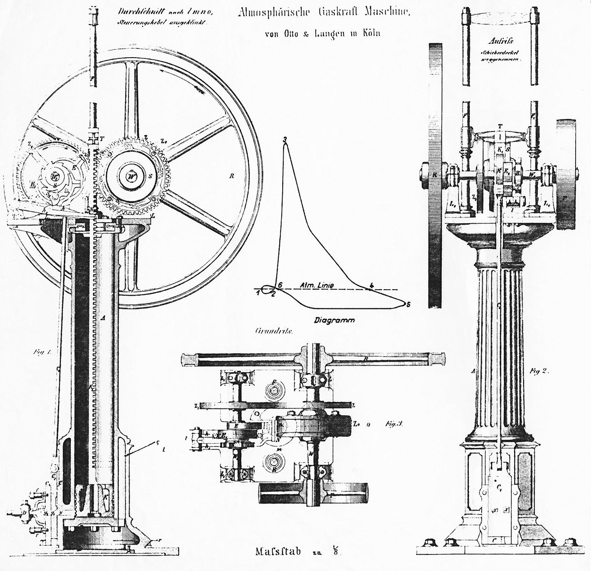
Drawing of the Otto-Langen engine circa 1866. Note the piston (K) and its rack (X) in the cylinder (A). The drawing also shows an early version of the over-running clutch (S).
Otto tried a wide-range of modifications to the Lenoir atmospheric engine in search of better performance. One interesting finding was that when the engine’s cylinder and piston were used to compress the incoming air and fuel charge, the resulting power stroke had enough energy to rotate the crankshaft through several revolutions. While Otto had discovered a number of improvements for the Lenoir atmospheric engine, creating a compression engine was a bit beyond the contemporary technology. Otto had already spent his saving and what he had borrowed from friends. To continue his research and develop an atmospheric engine, he needed money.
For some time, Eugen Langen ran his family’s sugar refining business in Cologne, Germany, but, like Nicolaus Otto, his true passion was for science and technology. Langen had become a fairly wealthy man from the family business and from a few of his own ventures. In 1863, his business was running smoothly, and he was looking for a new enterprise. Langen had read of the Lenoir engine and contemplated how such a device could benefit industry.
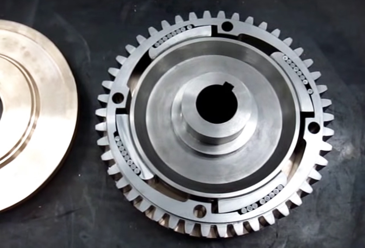
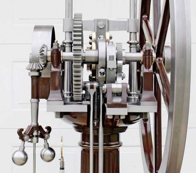
A reproduction of the over-running clutch built by Wayne Grenning of Grenning Models. Counterclockwise movement of the gear brings the shoes to their stops and allows the gear to rotate free from the inner hub. When the gear rotates clockwise, the shoes slide on their rollers until they are wedged between the gear and the inner hub, locking the two together. The clutch was originally designed by Franz Reuleaux, and later clutches used on the Otto-Langen had three shoes. (Wayne Grenning image)
Exactly how Otto and Langen met is not known. Perhaps Otto sought out Langen as a financial backer, or perhaps they met through a third party. Regardless, Langen witnessed Otto’s unrefined atmospheric engine running on 9 February 1864. Langen saw potential in the engine and its inventor. Langen and Otto formed N.A. Otto & Cie on 31 March 1864 to develop and manufacture internal combustion engines.
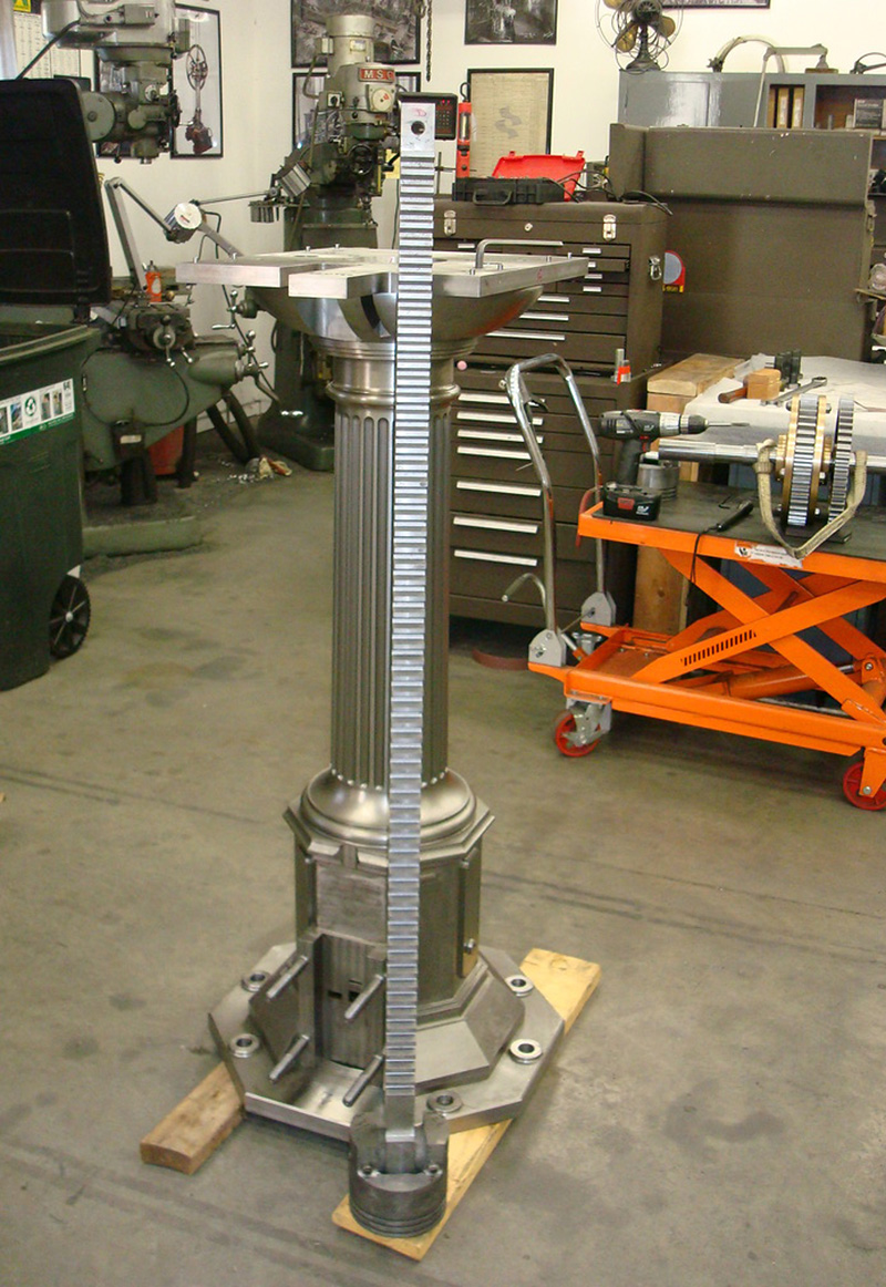
Other reproduction parts built by Wayne Grenning. The piston with its rack attached are shown outside of the cylinder housing column. The piston and rack weigh around 80 lb (36 kg). The studs seen at the base of the column are where the slide valve mounts. (Wayne Grenning image)
Three years of experimentation and refinement occurred before N.A. Otto & Cie had a marketable engine that was superior to the competition. The Otto-Langen .5 hp (.37 kW), single-cylinder, atmospheric engine made its public debut at the 1867 International Exposition in Paris, France (Exposition universelle de 1867). Nothing about the engine appeared remarkable, but interest piqued when a demonstration showed that the engine consumed half the gas of other engines of the same power. The engine’s remarkably efficient performance won it the grand prize.
The Otto-Langen engine consisted of a vertical column that formed a single cylinder. A free piston was installed in the cylinder, with the piston head facing down. Attached to the upper part of the piston was a rack gear that extended out vertically above the engine. The rack engaged the one-way, over-running (sprag) clutch that was mounted on the engine’s main drive shaft. The clutch was the first of its type and was designed by Franz Reuleaux. The flywheel was mounted on one side of the main drive shaft, and the belt drive pulley was mounted on the other side. On the flywheel side of the main drive shaft was the main drive gear. The main gear engaged an accessory gear, which drove the accessory shaft. Typically, the accessory gear was larger and had more teeth than the main gear. The difference resulted in an accessory gear speed slower than that of the main gear, which helped reduce impact forces on the accessory gear drive.
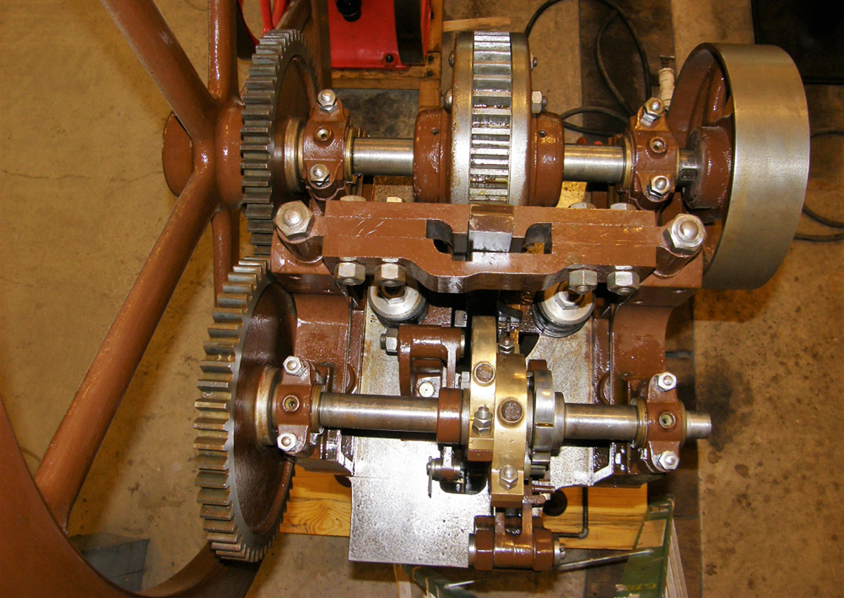
Top view of the Otto-Langen engine at the Rough and Tumble Engineers Historical Association in Kinzers, Pennsylvania. It is the oldest internal combustion engine in the Americas. Installed on the main drive shaft (top) from left to right are the flywheel, main drive gear, over-running clutch, and belt drive. Installed on the accessory shaft (bottom) from left to right are the accessory drive gear, secondary eccentric, main eccentric, and ratcheting gear. (Rough and Tumble Engineers image)
The accessory gear was mounted on and drove the accessory shaft. Also on the accessory shaft were two eccentrics and a ratcheting gear. The ratcheting gear was attached directly to and turned with the accessory shaft. The two eccentrics operated independently of the accessory shaft and were mostly stationary. A pawl would engage the ratcheting gear and drive the main eccentric. This eccentric lifted the piston and rack assembly and also drove the second eccentric, which operated the hand-scraped slide valve at the base of the engine via a control rod. When the eccentrics raised the piston and slide valve, the air and fuel mixture was draw into the cylinder. The slide valve then aligned to a port with an internal flame that ignited the gaseous mixture in the cylinder.
On the power stroke, the free piston had unrestricted upward movement in the cylinder and took advantage of the complete expansion of gases during the combustion process. As the piston moved up, the rack attached to the upper side of the piston moved freely on the clutch. As atmospheric pressure and gravity pulled the rack and piston back down, the rack engaged the over-running clutch that drove the main drive shaft. A flyball governor was driven by the accessory shaft and controlled an exhaust valve. With a closed exhaust valve, the piston could not fully descend. As the speed of the accessory shaft decreased below the desired rpm, the governor opened the exhaust valve, which allowed the piston to descend. This movement of the piston and its attached rack assembly tripped an arm that engaged the pawl to the ratcheting gear, driving the eccentrics and subsequently firing the engine.
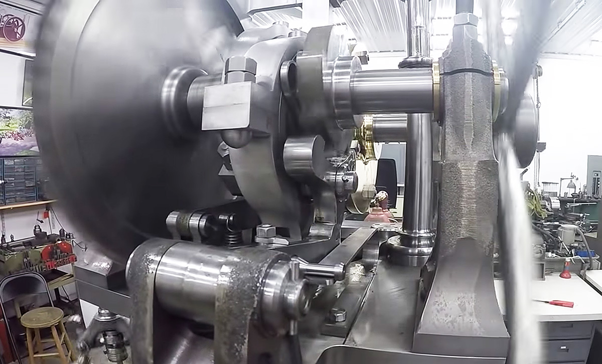
Grenning’s full-size reproduction of a .5 hp (.37 kW) Otto-Langen engine under power. The accessory shaft is in the foreground, and the pawl in the center of the image is about to engage the ratcheting gear. The ratcheting gear will then drive the eccentrics. (Wayne Grenning image)
The internal flame that ignited the gaseous mixture in the cylinder was extinguished on each power stroke. The internal flame was relit by an external flame via a port on the slide valve that aligned as the valve moved. The Otto-Langen engine was run on illuminating gas, which was typically distributed at around .07 psi (.005 bar). When firing, the engine needed more gas than the line could supply. An accumulator bag was used, which held a surplus of gas. The Otto-Langen engine would draw from the bag when firing, and the gas would be replenished between firings from the low-pressure supply line.
For cooling, an integral water jacket surrounded the cylinder. The Otto-Langen engine employed thermosyphon circulation. As the water was heated, it expanded out of a port in the upper part of the water jacket and flowed to an external reservoir. At the same time, cool water was drawn from the external reservoir and to the engine. The engine relied on manual, external lubrication, which could be (and was) supplied while the engine was in operation. The Otto Langen’s design and features allowed for a quick start and continuous running.
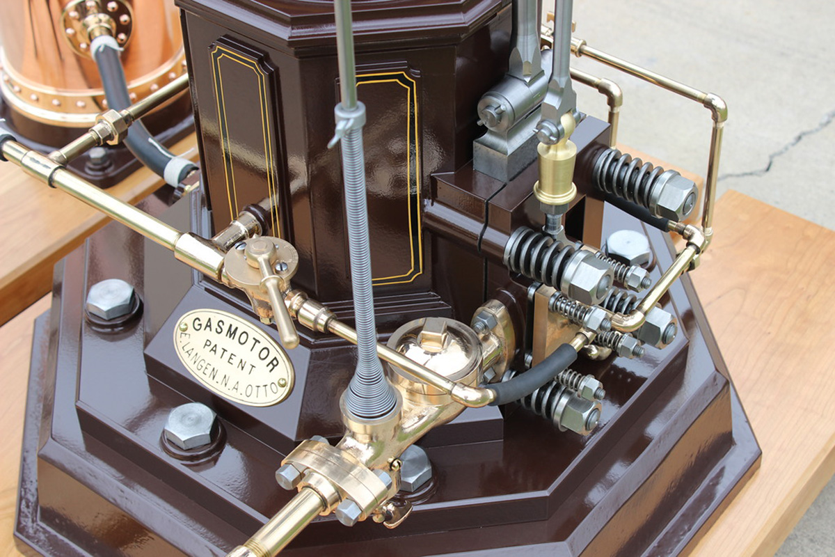
The base of Grenning’s Otto-Langen reproduction shows the safety slide valve (with brass connector) and the main slide valve behind it. The main slide valve was operated by the secondary eccentric. The rod with the coiled spring is the governor-controlled exhaust valve. Later engines did not have the safety slide valve, and the governor controlled the pawl’s engagement. (Wayne Grenning image)
Because of the free piston, cylinder firing was not directly linked to the rpm of the drive shaft. With a light load, the cylinder could fire once for every 25 revolutions of the main drive shaft. Under heavy loads, the cylinder could fire once for every two revolutions. The engine was typically operated with a main drive shaft speed of 90 rpm. However, the speed could be increased to 120 rpm or decreased to around 30 rpm. The high and low speeds were dictated by the mechanical limitations of the eccentrics and slide valve movement.
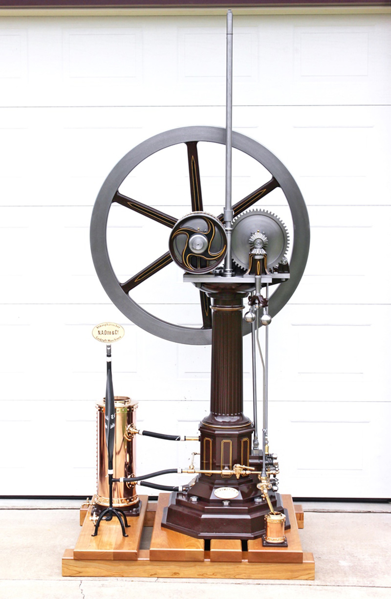
Grenning’s completed Otto-Langen reproduction is a fantastic display of a modern-day master-craftsman’s appreciation of old-world engineering. After spending years researching the Otto-Langen, it took Grenning 14 months to build his reproduction engine. (Wayne Grenning image)
The cylinder housing on the early Otto-Langen engines was fluted and resembled a Grecian column, but this expensive feature was not included on later engines. In addition, early engines did not have a governor and had a second slide valve. The secondary slide valve acted as a safety feature to cut the gas flow to the cylinder. Extensive engine operation showed that the safety slide valve was not needed, and it was eliminated to cut down on manufacturing costs.
The success at the International Exposition in Paris brought in a flood of orders that N.A. Otto & Cie could not fulfill due to a lack of existing capital. Ludwig August Roosen-Runge, a businessman from Hamburg, lent financial support, and the company was renamed Langen, Otto & Roosen in 1869. That same year, the factory was relocated to Deutz, Germany. More capital was sought and found, and a new company, Gasmotoren-Fabrik Deutz AG (Deutz), was established in January 1872. That same year, Gottlieb Daimler and his protégé, Wilhelm Maybach, joined Deutz.
Maybach was tasked with redesigning the Otto-Langen engine to simplify its construction and lower its production cost. The updated design eliminated the accessory shaft and ran everything from the main drive shaft. The governor controlled cylinder firing with the pawl and not with the exhaust valve. The updated engine was available at the end of 1873.
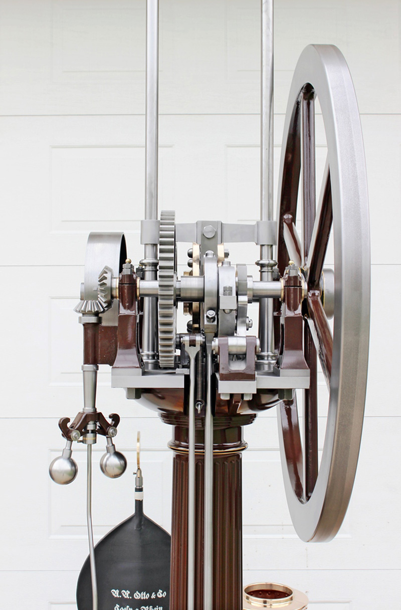
View of the accessory shaft on Grenning’s engine. The left side of the shaft drives the flyball governor. In the background are the black gas accumulator bag and copper water reservoir. (Wayne Grenning image)
The .25 hp (.19 kW) version was the smallest Otto-Langen, and it stood 7 ft (2.1 m) tall and weighed 900 lb (408 kg). To make more power, the engine was basically scaled-up to a larger size. However, the design of the Otto-Langen engine limited just how large the engine could be while still being practical. With its vertical cylinder and long rack attached to the piston, the Otto-Langen was a tall and heavy engine. There were practical limits on the engine’s height and weight. The vertical piston had a tendency to send significant vibrations through the ground with every stroke. This shook foundations, could damage nearby equipment, and made most above ground level installations unfeasible. The largest Otto-Langen engine was the 3 hp (2.24 kW) model. It was 12.7 ft (3.9 m) tall and weighed 4,450 lb (2,018 kg).
The .5 hp (.37 kW) Otto-Langen engine created its power at 110 rpm at the flywheel with 40 power strokes per minute. The cylinder had a 5.9 in (150 mm) bore and a 38.7 in (985 mm) maximum stroke. Maximum displacement was 1,062 cu in (17.4 L). The engine was 8.8 ft (2.65 m) tall and weighed 1,600 lb (725 kg). The piston and rack assembly of the .5 hp (.37 kW) engine weighed around 80 lb (36 kg).
The 2 hp (1.49 kW) engine operated at 90 rpm at the flywheel with 30 power strokes per minute. The cylinder had a 12.5 in (318 mm) bore and a 40.5 in (1,030 mm) maximum stroke. Maximum displacement was 4,992 cu in (81.8 L). The 2 hp (1.49 kW) engine was 10.7 ft (3.25 m) tall and weighed 4,000 lb (1,815 kg). The piston and rack alone weighed 116 lb (52.6 kg).
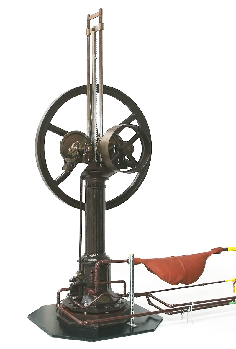
The first Otto-Langen engine is on display in the Deutz Technikum Engine Museum in Cologne, Germany. This engine has no governor, and the safety slide valve was removed sometime after the engine was built. The gas accumulator bag is on the right. (Wayne Grenning image)
By 1875, there was competition in the form of George Brayton’s Ready Motor and other engines. Otto felt that the atmospheric engine had reached its zenith, yet Daimler was still interested in pursuing the type. Tension existed between Otto and Daimler, and the men did not work well together. In 1876, Otto first ran his four-stroke, internal combustion engine using the combustion cycle that would revolutionize the world. Development of the Otto-Langen engine stopped around 1877, and production of the engine at Deutz stopped around 1878. Daimler and Maybach left Deutz in 1880 and formed a new company to develop engines and automobiles. The Deutz company is still in business designing and manufacturing internal combustion engines.
Between 1864 and 1882, Deutz and its predecessors built 2,649 Otto-Langen engines. Around 2,000 more engines were built by subsidiaries or under license in Austria (Langen & Wolf), Belgium (E. Schenck & Co.), Britain (Crossley Brothers), and France (Sarazin / Panhard). For a brief time, the Otto-Langen atmospheric engine led the industry, and it was the world’s first commercially successful internal combustion engine. Perhaps the Otto-Langen’s greatest achievement was to serve as a stepping stone to the four-stroke, Otto-cycle engine. Around 23 Otto-Langen engines survive, including the very first engine built, which won the grand prize in 1867. The over 150-year-old first engine is on display at the Deutz Technikum Engine Museum in Cologne, Germany, and it is run on special occasions.
Wayne Grenning of Grenning Models has built a number of reproduction Otto-Langen engines. He gives a detailed explanation of the engine’s operation in the video below.
Sources:
– Internal Fire by C. Lyle Cummins, Jr. (1989)
– Flame Ignition by Wayne S. Grenning (2014)
– Startup & Instructional Explanation of 1867 Otto Langen Engine Operation by Wayne Grenning (5 March 2017)
– https://sites.google.com/site/wgrenning/home
– “Improvements in Air-Engines,” US patent 67,659 by Eugen Langen and Nicol. Auguste Otto (granted 13 August 1867)
– “Improvements in Gas-Motor Engines,” US patent 153,245 by Gottlieb Daimler (granted 21 July 1874)
– https://collection.maas.museum/object/207174
– http://www.roughandtumble.org/ottolangen