By William Pearce

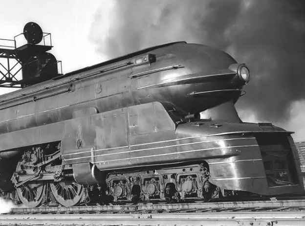
The Pennsylvania Railroad S1 engine 6100 in February 1939, shortly after completion. The S1 was the longest and heaviest rigid frame reciprocating steam passenger locomotive ever built. Note the dual stacks protruding slightly above the engine’s streamlined claddin
The Pennsylvania Railroad (PRR) was founded in 1846 and headquartered in Philadelphia, Pennsylvania. In the first half of the 20th century, PRR was the largest railroad by traffic and revenue in the United States. At one time, PRR was the largest publicly traded corporation in the world, with a budget larger than that of the U.S. government and a workforce of approximately 250,000 people.
In 1937, PRR sought to design a coal-burning steam locomotive that would pull heavy passenger trains for long runs at better than 60 mph (97 km/h). Accomplishing such tasks typically required the use of two engines pulling a single train (double-heading). PRR also hoped that the performance of the new engine would match that of the new electric locomotives just then coming into service. The new steam locomotive would serve as an experimental prototype for the railroad as it worked to modernize its fleet. The new locomotive was designated as the S1 class, and PRR collaborated with the American Locomotive Company, the Baldwin Locomotive Works, and the Lima Locomotive Works in designing and building the engine. The S1 was built in PRR’s Altoona Works in Altoona, Pennsylvania during 1938. The S1 was given the Altoona serial number 4341 and the PRR number 6100.
The PRR S1 was a unique duplex locomotive that utilized a 6-4-4-6 wheel arrangement. A six-wheel leading truck with 36 in (.91 m) wheels was positioned at the front of the engine. A set of four 84 in (2.13 m) drive wheels followed, trailed by another identical set of four drive wheels. A six-wheel trailing truck with 42 in (1.07 m) wheels was positioned at the rear of the engine. What made the S1 a duplex locomotive was its use of two separate pairs of cylinders mounted to a rigid frame. Each cylinder pair drove a set of four drive wheels. The two trucks and four pairs of drive wheels were mounted to a single-piece frame bed made of cast steel by General Steel Castings in St Louis, Missouri. The cylinders and their valve chests were integrally cast with the frame. The frame was 77 ft 9.5 in (23.7 m) long, weighed 97,620 lb (44,280 kg), and was the largest locomotive bed casting ever made. However, the use of a long rigid frame meant that the engine would not be able to operate on tracks with significant curves.

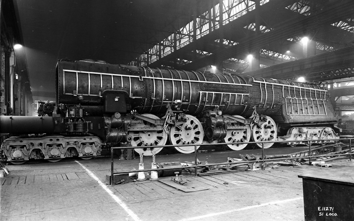
The S1 under construction with its large firebox and boiler being attached to the engine’s huge cast steel frame. While mostly concealed, the single-piece frame can be seen supporting the leading and trailing truck
With an overall length of 140 ft 2.5 in (42.7 m), the S1 was the longest rigid frame reciprocating steam passenger locomotive ever built, a fact that earned it the nickname The Big Engine. The S1 was made up of an 81 ft 1.75 in (24.7 m) long engine and a 59 ft .75 in (18.0 m) long tender that carried the locomotive’s coal and water. The engine weighed 608,170 lb (275,862 kg), and its weight was distributed with 135,100 lb (61,280 kg) on the leading truck, 191,630 lb (86,922 kg) on the trailing truck (326,730 lb / 148,202 kg total on the trucks), and 281,440 lb (127,659 kg) on the driving wheels. This distribution meant that less than half (46.28%) of the engine’s weight was on the driving wheels, a configuration that often led to wheel slip.
The tender was supported by two eight-wheel trucks with 36 in (.91 m) wheels. It carried 53,000 lb (24,040 kg) of coal in a front compartment and 24,230 gallons (91,720 L) of water in a rear compartment. When combined with the engine, the 451,840 lb (204,951 kg) tender gave the S1 a total weight of 1,060,010 lb (480,813 kg). The locomotive was 15 ft 6 in (4.7 m) tall and 10 ft 7 in (3.2 m) wide.

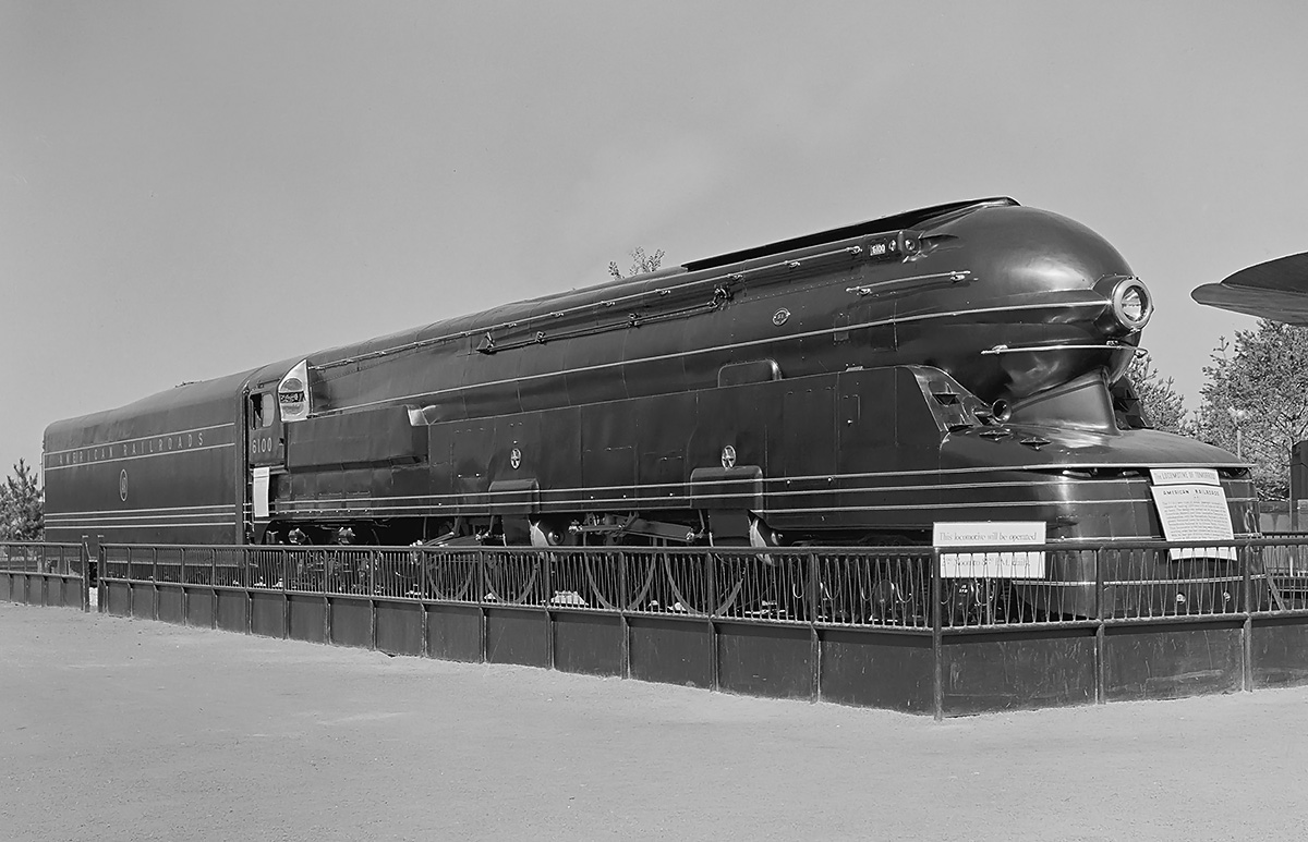
The S1 atop its special display stand at the 1939 New York World’s Fair. The stand enabled the engine to operate daily at up to 60 mph (97 km/h). Note that the tender is painted as “American Railroads.”
An HT type mechanical stoker auger transported coal from the tender to the engine’s firebox. The firebox was 198 in (5.03 m) long and 96 in (2.44 m) wide. Coal was burned in the firebox at around 2,000 °F (1,093 °C). Heat from the firebox flowed through the boiler via 219 tubes that were 2.25 in (57.2 mm) in diameter and 69 flues that were 5.5 in (139.7 mm) in diameter. Each of the tubes and flues was 22 ft (6.7 m) long. The 288 tubes and flues would stretch for 6,336 ft (1,931 m) if laid end to end. The boiler was made from approximately 1 in (254 mm) thick nickel steel. After passing through the tubes, the soot, embers, smoke, and heat from the burning coal flowed into a smokebox at the front of the engine and was subsequently vented into the atmosphere via dual vertical stacks. Spent steam from the cylinders was directed through the smokebox and helped create the draft that drew air into the firebox, through the tubes, and out the stacks. The stacks were approximately 21 in (533 mm) in diameter and protruded 4.875 in (124 mm) above the top of the engine.
The tubes, flues, and firebox of the S1 had a combined evaporative surface area of 5,661 sq ft (525.9 sq m). Heat radiating from these surfaces turned water in the boiler to steam and built up a working pressure of 300 psi (20.7 bar). With a temperature of over 420 °F (215 °C), the wet, saturated steam was collected from slots along the top of a pipe inside the boiler shell. The steam then flowed to the modified Type A superheater, which had a surface area of 2,085 sq ft (193.7 sq m). From the superheater, 69 small superheater elements (tubes) took the wet steam back into the flues. The steam inside the superheater elements was heated well above its saturation value and converted to dry, superheated steam. The superheater elements delivered the dry steam to the steam chamber in the superheater.

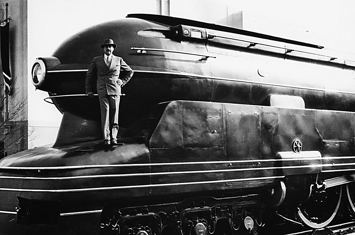
Raymond Lowey proudly poses with the S1 at the 1939 New York World’s Fair. The engine is mounted on its display stand, and a roller can be seen under the front drive wheel.
The flow of steam in and out of each of the engine’s four cylinders was controlled by a Walschaerts valve gear. A 12 in (305 mm) diameter piston spool valve was mounted in a valve chest above each cylinder. The steam-distribution valve slid back and forth 7.5 inches (191 mm) to allow steam to enter one side of the double-acting cylinder while simultaneously opening the other side to exhaust the previous steam charge. The steam flowed from the center of the valve chest into the front of the cylinder and filled its 9,883 cu in (162 L) volume, pushing the 22 in (558.8 mm) diameter piston back 26 in (660.4 mm) to the rear of the cylinder. The valve then slid rearward to direct steam into the rear part of the cylinder and allow the front part of the cylinder to exhaust. Steam entering the rear part of the cylinder pushed the piston forward to its original position. The cylinder had a smaller return volume of approximately 9,321 cu in (153 L) on account of the 5.25 in (133 mm) diameter piston rod taking up some room. The piston rod extended straight back from the cylinder and was attached to the connecting rod via a crosshead. The connecting rod linked the piston rod to the rear driving wheel in the two-wheel set on each side of the engine. Here, the connecting rod was attached to the coupling rod, which connected the two driving-wheel sets together. The reciprocating parts for each of the four two-wheel driving sets weighed 1,010 lb (458 kg). To aid traction, sand could be deposited on the rails in front of all four front drive wheels and in front of the last pair of rear drive wheels. Two sand boxes were positioned on each side of the engine.
The S1 was designed to haul a 1,200-ton (1,089-t) passenger train at 100 mph (161 km/h). The engine developed around 6,500 indicated hp (4,847 kW) at 100 mph (161 km/h) and had a maximum tractive effort of some 76,400 lbf (339.8 kN) based on an 85% efficiency factor. Without any slip, each rotation of the drive wheels moved the engine 22 ft (6.7 m). At 100 mph (161 km/h), each drive wheel rotated 400 times a minute, and each double-acting piston made 800 strokes. This resulted in roughly 17,781 cu ft (503.5 cu m) of steam passing through the S1’s four cylinders every minute.

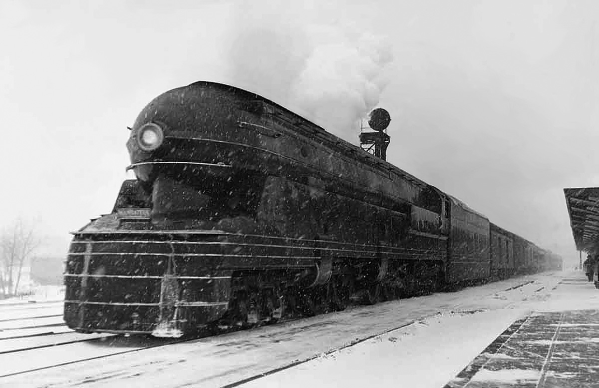
Early in its life, the S1 heads east from Englewood Union Station as the “Manhattan Limited.” The nameplate at the front of the engine says “Manhattan.” Note that all of the engine’s skirting and paneling is in place.
The S1 was encased in Art Deco-styled cladding designed by Raymond Loewy. The streamlined cladding consisted of aluminum panels that covered the boiler and extended to a bullet-shaped nose at the front of the engine. Skirt panels covered the lower part of the engine and partially concealed the running gear. The cladding was adorned with chrome handrails and trim accents. The S1’s low-profile stacks were concealed in a fairing atop the engine. Loewy had worked with PRR when he designed the streamlined cladding for the K4 engine 3768 in 1936. Additional K4 engines were streamlined, but not to the extent of 3768. Loewy’s S1 styling was a direct development of his work on engine 3768. It is often claimed that Loewy was awarded US patent 2,128,490 for his S1 design, but this patent was applied for on 17 July 1936 and actually details his work on the K4 engine 3768.
Completed on 31 January 1939, the S1 cost PRR approximately $669,780 USD to build, which is equivalent to $11,912,085 USD in 2018. After undergoing some initial testing, the S1 was showcased at the 1939 World’s Fair held at Flushing Meadows Corona Park on Long Island, New York from 30 April 1939 to 27 October 1940. The entire railroad display was sponsored by 27 railroads from the eastern United States. Still numbered as 6100, the S1 was branded “American Railroads” rather than the “Pennsylvania” it wore later in life. The S1 sat atop a special stand that enabled the locomotive to be operated at speed under its own power. In the stand, the engine’s drive wheels powered generators. Electricity created by the generators was used to power motors that turned the 12 wheels of the leading and trailing trucks and the 16 wheels on the tender. The drive system in the stand was configured so that all wheels turned at the same rpm. While the display was open during the 16-month fair, the S1 was operated daily from 12:00 PM to 8:00 PM at 60 mph (97 km/h). By the end of the fair, the S1 had traveled some 50,000 miles (81,467 km) without moving from the stand.

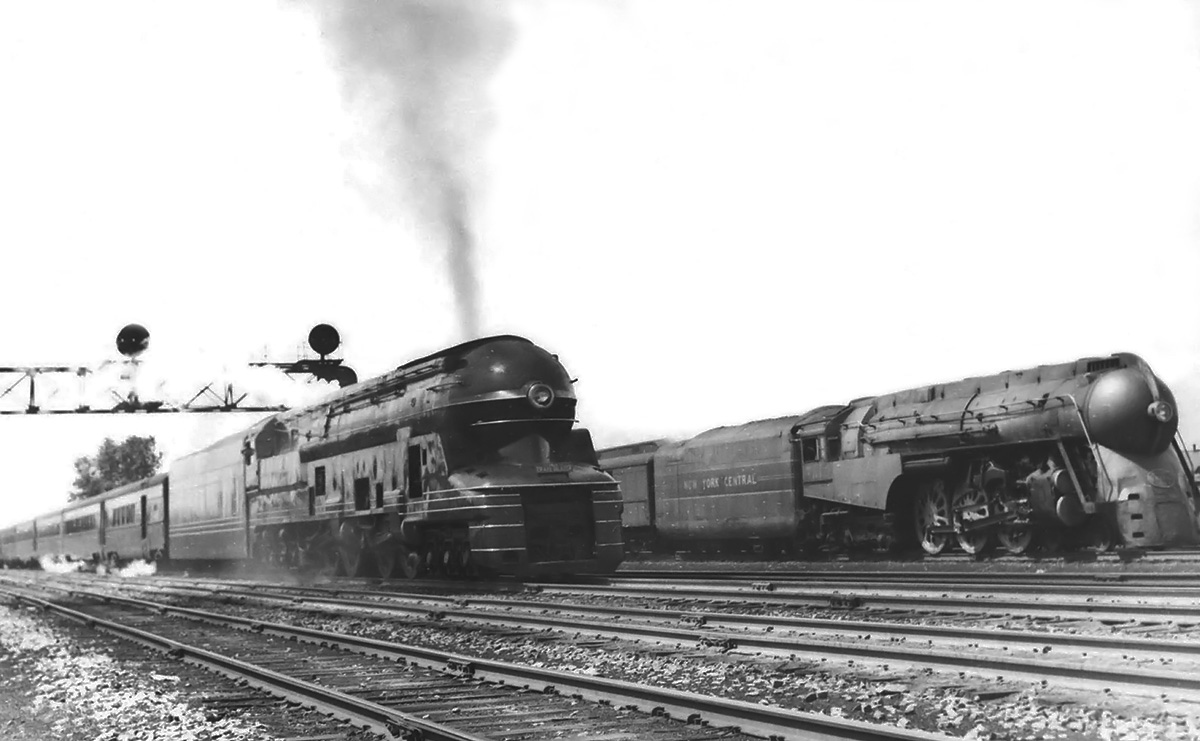
The S1 moves east from Englewood Union Station as the “Trailblazer.” In service, the S1 began to lose some of its skirting and paneling, like the piece at the front of the engine. The panels were removed for access and often never replaced. A New York Central J-3a 4-6-4 Hudson occupies another track.
After the fair, the S1 was finally pressed into service for the PRR in December 1940. While the S1 made for an impressive sight on its special display stand, operating the engine on standard track presented some difficulties. The wide, long, and heavy rigid locomotive could not operate on tracks with tight turns or obstructions, which included most of PRR’s system. PRR sent the S1 to operate on a 283-mile (455-km) straight route of the main line from Chicago, Illinois to Crestline, Ohio. Special facilities were built in Crestline to house and maintain the S1. Even so, the locomotive occasionally derailed during turning operations on a special section of wye track.
In the early 1940s, the S1 was operated in profitable service pulling one of the longest passenger trains for PRR—a 2,000-ton (1,814-t) train consisting of 22 cars. The S1 was popular with crews because of its speed, power, and smooth ride. However, the majority of the S1’s weight rested on the leading and trailing trucks rather than on the engine’s eight drive wheels. Frequent wheel slip was an issue—the engineer needed to be careful opening the throttle, and the duplex engine arrangement made it difficult to quickly detect when the drive wheels were slipping. Wheel slip at speed would quickly damage drive components. Some of the S1’s aerodynamic skirting was removed to ease inspection and maintenance. The discarded skirting also allowed better access to the engine’s 350 grease fittings that needed daily servicing. On a standard 283-mile (455-km) run between Chicago and Crestline, the S1 consumed 48,000 lb (21,772 kg) of coal and 36,000 gallons (136,275 L) of water.

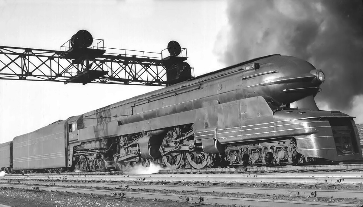
All of the skirting has been removed from the S1’s drive wheels and trailing truck. While the S1 proved to be quite capable of pulling passenger trains at high speeds, it was too big for most tracks and suffered from wheel slip.
In service, the S1 would regularly top 100 mph (161 km/h). On a test run with 12 loaded cars, Charlie Wappes, assistant road foreman of PRR’s Fort Wayne division, observed the S1’s speedometer needle pegged at the gauge’s 110 mph (177 km/h) maximum. Wappes pulled out his stopwatch and timed the train from the Wanatah, Indiana station to the Hanna, Indiana station. The S1 covered the 6.3-mile (10.1-km) distance in 170 seconds, a time that averages to 133.4 mph (214.7 km/h). Other second-hand reports indicate the S1 traveling over 140 mph (225 km/h) on multiple occasions, and an inconceivable top speed of 156 mph (251 km/h) was claimed on a run between Fort Wayne, Indiana to Chicago, Illinois. PRR was reportedly fined for this speed, as the track’s limit was 80 mph (129 km/h). The official (and still current) speed record for a steam locomotive was set by the British LNER (London and North Eastern Railway) Class A4 4468 Mallard at 125.88 mph (202.58 km/h) on 3 July 1938. While it seems possible that the S1 may have been able to break the record, the S1 never made any official speed record attempts, and there is no official documentation that corroborates these high-speed claims.
The S1 was purely an experimental engine, and its operation was very limited. The locomotive was too long for almost all railway turntables, and its long rigid frame could not take the curves into most railyards. But, the S1’s wheel slip trouble, caused by the majority of the engine’s weight resting on the trucks rather than the drive wheels, was perhaps the engine’s biggest issue. After just a few years of operation, the sole S1 was removed from service. Some sources indicate the S1’s last run was in December 1945, while other sources give the date as May 1946. Regardless, the impressive, powerful, and ultimately unsuccessful S1 engine 6100 was scrapped in 1949. However, some of the lessons learned from the S1 were applied to the last steam locomotives built by the PRR, the 4-4-4-4 engines of the T1 class.

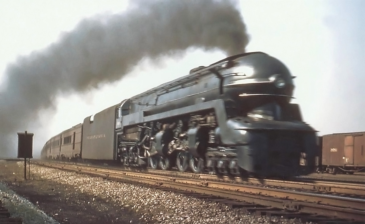
The S1 under power late in its life with all of its skirting removed. In addition, the trim is gone from the front of the engine, and the tender has been repainted without any striping. Note the separate cylinders connected to the drive wheels.
Sources:
– Loco Profile 24: Pennsylvania Duplexii by Brian Reed (June 1972)
– Pennsy Power (I) by Alvin F. Staufer (1962)
– “High-Capacity Locomotive for Fast Service” Railway Age Vol. 106, No. 25 (24 June 1939)
– “Riding the Gargantua of the Rails” by Roderick M. Grant, Popular Mechanics (December 1941)
– https://en.wikipedia.org/wiki/Pennsylvania_Railroad_class_S1
– https://en.wikipedia.org/wiki/Pennsylvania_Railroad
– http://www.steamlocomotive.com/locobase.php?country=USA&wheel=Duplex&railroad=prr
– http://www.crestlineprr.com/duplexexperimentals.html
– http://www.dieselpunks.org/profiles/blogs/sunday-streamline-14-the-big
– http://streamlinermemories.info/?p=5258