Monthly Archives: March 2019

LWF H Owl nose 1923

LWF Model H Owl Mail Plane / Bomber

By William Pearce

In 1915, the Lowe, Willard & Fowler Engineering Company was formed in College Point, Long Island, New Work. Of the founders, Edward Lowe, provided the financing; Charles Willard was the engineer and designer; and Robert Fowler served as the shop foreman, head pilot, and salesman. Willard was previously employed by the Curtiss Aeroplane and Motor Company and had developed a technique for molding laminated wood to form a monocoque fuselage. Willard was eventually granted U.S. patent 1,394,459 for his fuselage construction process. Previously in 1912, Fowler became the first person to fly west-to-east across the United States.

LWF H Owl nose

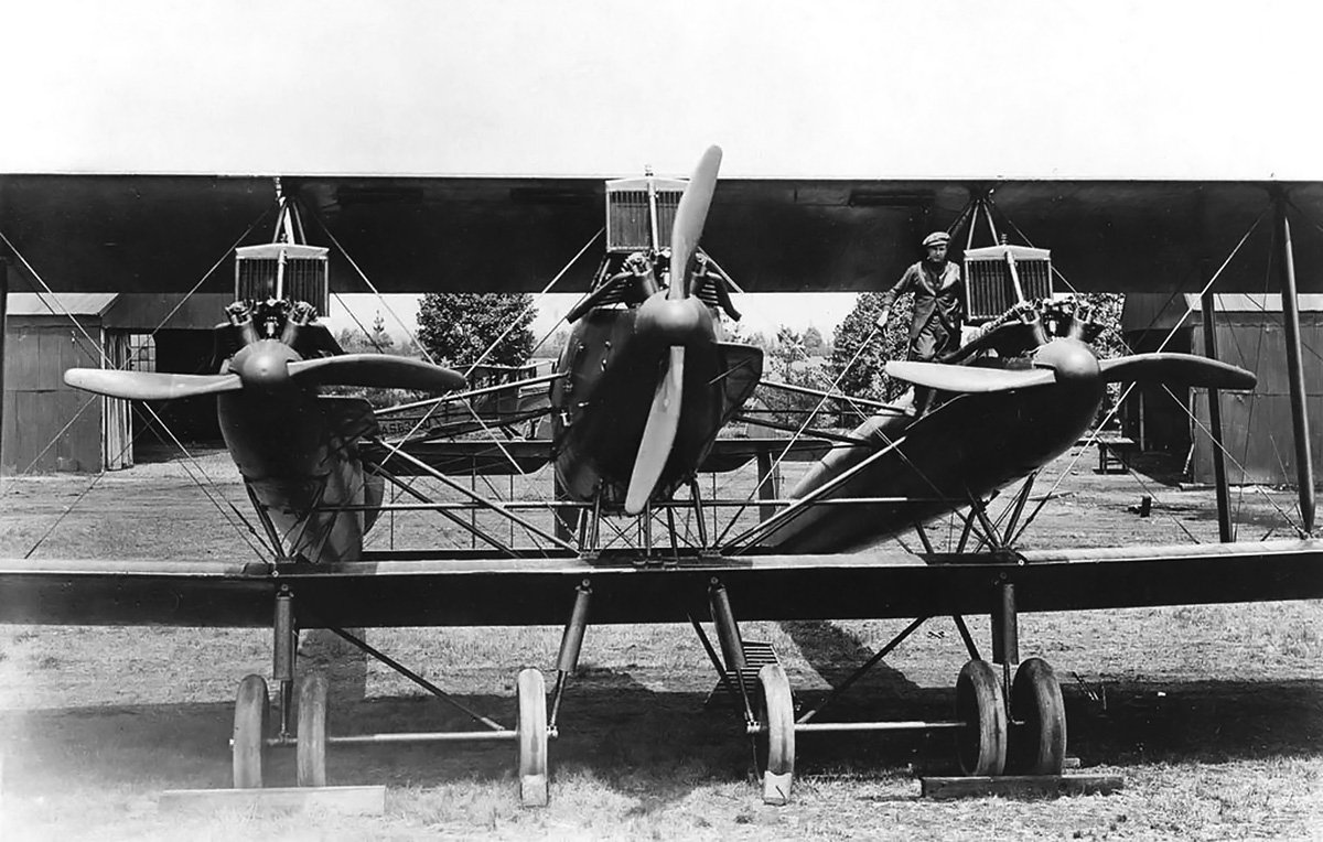
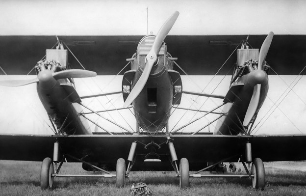
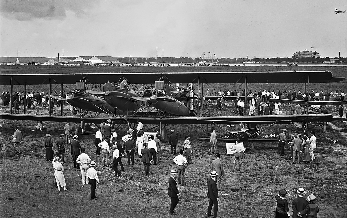
The LWF Model H Owl in its original configuration with six main wheels. The engine on the central nacelle has a spinner, a single service platform, and a separate radiator. Note the numerous drag inducing struts and braces for the wings, nacelle, and booms.

The business partnership was short-lived. In 1916, Fowler and Willard left the company, and Lowe assumed control, renaming the company LWF Engineering. By this time, LWF had become well-known for its molded wood construction process. However, management changed again as other financiers forced Lowe out. In 1917, the firm was reorganized as the LWF Engineering Company, with “Laminated Wood Fuselage” taking over the LWF initials.

By 1919, LWF began design work on a large trimotor aircraft intended for overnight mail service between New York City and Chicago, Illinois. Other uses for the aircraft were as a transport or bomber. Designated the Model H (some sources say H-1), construction began before an interested party came forward to finance the project. Because of its intended use for overnight mail service, the aircraft was given the nickname “Owl.” As construction continued, the United States Post Office Department declined to support the Model H. However, LWF was able to interest the United States Army Air Service, which purchased the aircraft on 16 April 1920. The Model H was assigned the serial number A.S.64012.

LWF H Owl rear

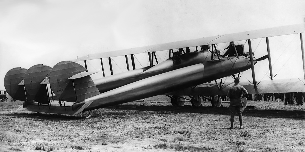
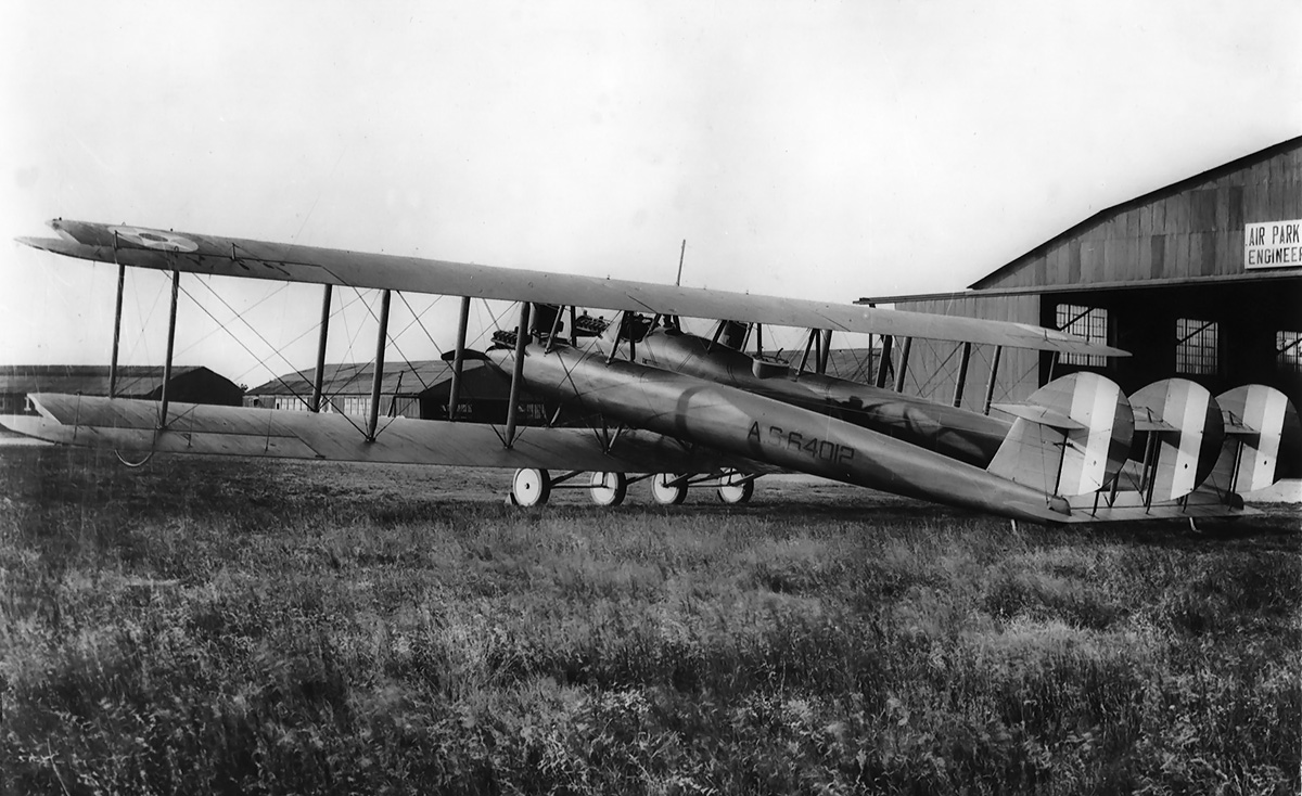
In the original configuration, the Owl’s cockpit was just behind the trailing edge of the wing, and visibility was rather poor. Note the aircraft’s two horizontal stabilizers and three rudders. The smooth surface finish of the booms is well illustrated.

The LWF Model H Owl was designed by Raoul Hoffman and Joseph Cato. Although the Owl’s design bore some resemblance to contemporary large aircraft from Caproni, there is nothing that suggests the similarities were anything more than superficial. The Model H had a central nacelle pod that was 27 ft (8.23 m) long and contained a 400 hp (298 kW) Liberty V-12 positioned in the nose of the pod. The cockpit was positioned in the rear half of the pod, just behind the wing’s trailing edge. The cockpit’s location did not result in very good forward visibility. Accommodations were provided for two pilots, a radio operator, and a mechanic. Mounted 10 ft (3.05 m) to the left and right of the central pod were booms measuring approximately 51 ft (15.54 m) long. The booms were staggered 24 in (.61 m) behind and 16 in (.41 m) below the central pod and extended back to support the tail of the aircraft. At the front of each boom was a 400 hp (298 kW) Liberty V-12 engine. Each boom housed fuel tanks and small compartments for cargo. The main load was carried in the central nacelle.

The monocoque central nacelle and booms were made using LWF’s laminated wood process. The construction method consisted of a mold covered with muslin cloth. Strips of thin spruce were then laid down and spiral wrapped with tape. Another layer of spruce was laid in the opposite direction and spiral wrapped with tape. The final, outer layer of spruce was laid straight. The assembly was then soaked in hot glue and covered with fabric and doped. The resulting structure was about .25 in (6.4 mm) thick, was very strong, and had a smooth exterior. Where reinforcement was needed, formers were attached to the inside of the structure.

LWF H Owl in flight

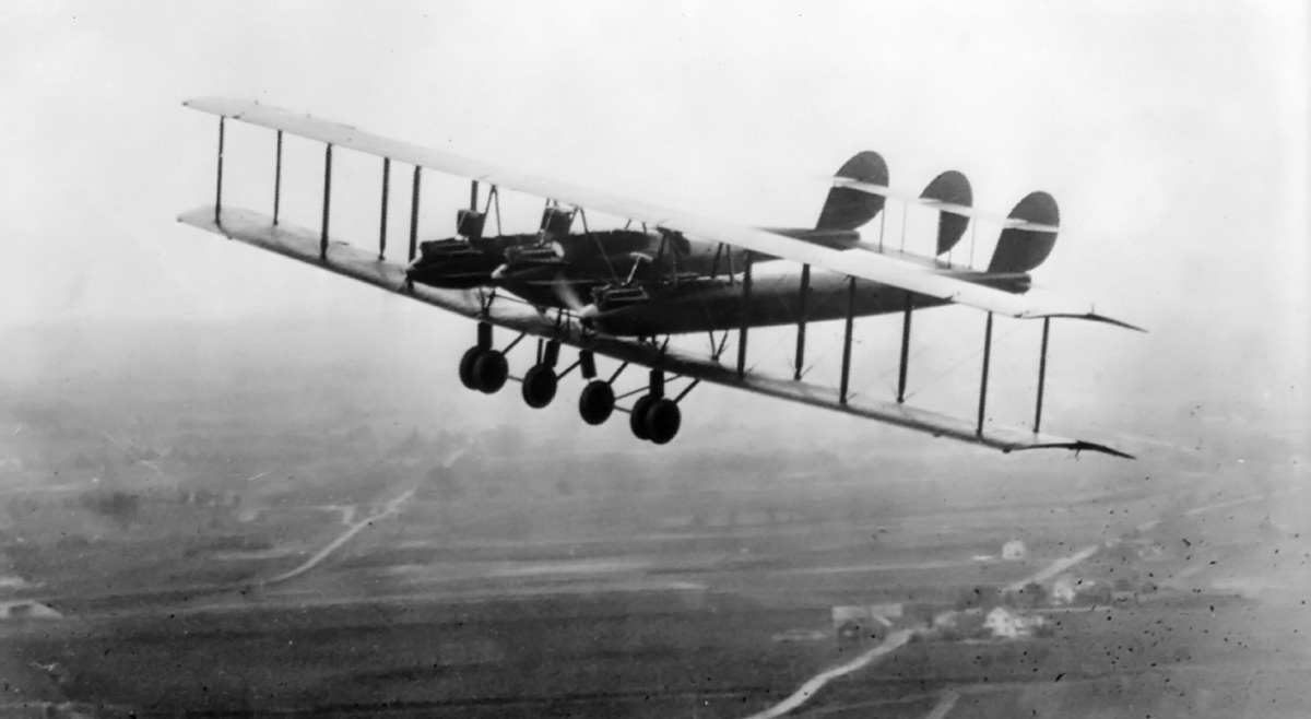
The Owl was a somewhat sluggish flier and reportedly underpowered. However, its flight characteristics were manageable. It was the largest aircraft in the United States at the time.

The nacelle and booms were mounted on struts and suspended in the 11 ft (3.35 m) gap between the Model H’s biplane wings. The wings were made of a birch and spruce frame that was then covered in fabric, except for the leading edge, which was covered with plywood. The upper and lower wing were the same length and were installed with no stagger. The wings were braced by numerous struts and wires. Large ailerons were positioned at the trailing edge of each wing. The wings were 100 ft 8 in (30.68 m) long with an additional 26 in (.66 m) of the 17 ft 8 in (5.38 m) ailerons extending out on each side. The incidence of the upper and lower wings was 4.5 and 3.5 degrees respectively. A bomb of up to 2,000 lb (907 kg) could be carried under the center of the lower wing.

A horizontal stabilizer spanned the gap between the rear of the booms. A large, 24 ft (7.32 m) long elevator was mounted to the trailing edge of the stabilizer. Mounted at the rear of each boom was a vertical stabilizer with a large 6 ft 9.75 in (2.08 m) tall rudder. A second horizontal stabilizer 28 ft (8.53 m) long was mounted atop the two vertical stabilizers. A third (middle) rudder was positioned at the midpoint of the upper horizontal stabilizer. Attached to the upper horizontal stabilizer and mounted between the rudders were two elevators directly connected to the single, lower elevator. The lower stabilizer had an incidence of 1.5 degrees, while the upper stabilizer had an incidence of 4 degrees.

LWF H Owl crash 1920

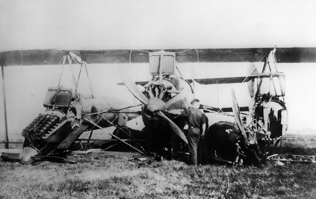
The Model H was heavily damaged following the loss of aileron control and subsequent hard landing on 30 May 1920. However, the booms, central nacelle, and tail suffered little damage.

The Owl’s ailerons and rudders were interchangeable. Each engine was installed in an interchangeable power egg and turned a 9 ft 6 in (2.90 m) propeller. Engine service platforms were located on the inner sides of the booms and the left side of the central nacelle. The Owl was equipped with a pyrene fire suppression system. The aircraft was supported by a pair of main wheels under each boom and two main wheels under the central nacelle. At the rear of each boom were tailskids.

The LWF Owl had a wingspan of 105 ft (32 m), a length of 53 ft 9 in (16.38 m), and a height of 17 ft 6 in (5.33 m). The aircraft had a top speed of 110 mph (117 km/h) and a landing speed of 55 mph (89 km/h). The Model H had an empty weight of 13,386 lb (6,072 kg) and a maximum weight of 21,186 lb (9,610 kg). The aircraft had a 750 fpm (3.81 m/s) initial rate of climb and a ceiling of 17,500 ft (5,334 m). The Owl had a range of approximately 1,100 miles (1,770 km).

LWF H Owl crash 1921

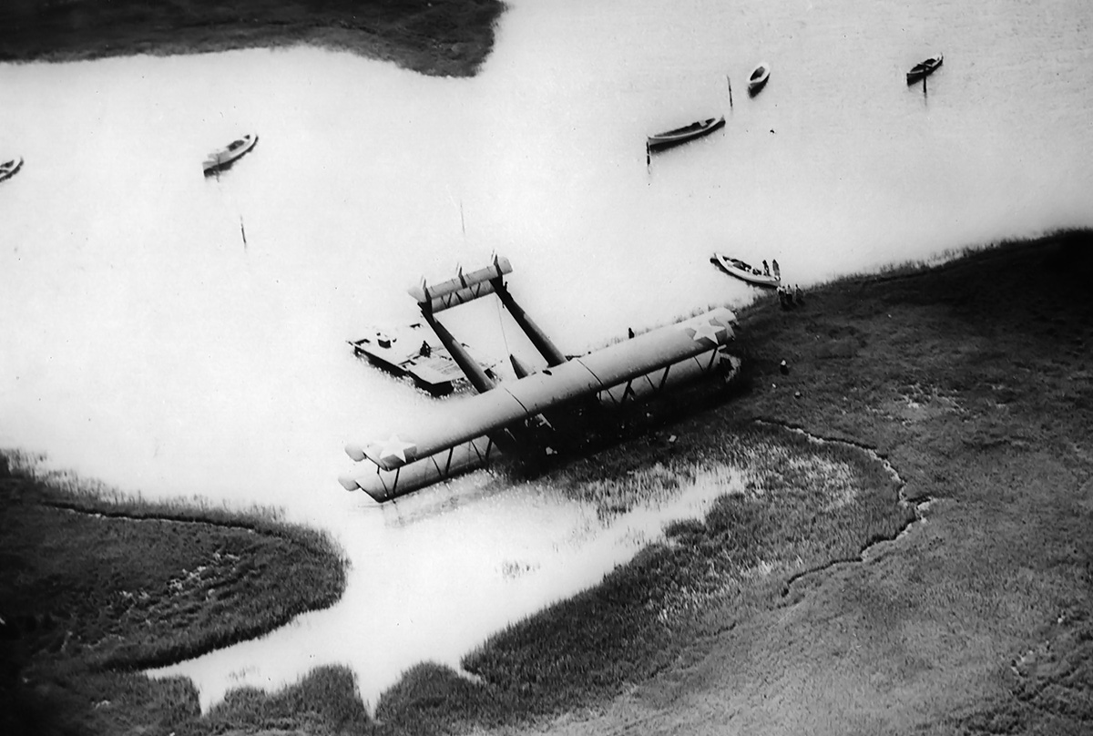
The Owl on its nose in the marshlands just short of the runway at Langley Field on 3 June 1921. The nose-over kept the tail out of the water and probably prevented more damage than if the tail had been submerged.

Although not complete, the Model H was displayed at the New York Aero Show in December 1919. On 15 May 1920, the completed Owl was trucked from the LWF factory to Mitchel Field. Second Lt Ernest Harmon made the aircraft’s first flight on 22 May. The aircraft controls were found to be a bit sluggish, but everything was manageable. An altitude of 1,300 ft (396 m) was attained, but one engine began to overheat, and the aircraft returned for landing. The second and third flights occurred on 24 May, with a maximum altitude of 2,600 ft (792 m) reached. The fourth flight was conducted on 25 May. Water in the fuel system caused the center engine to lose power, and an uneventful, unplanned landing was made at Roosevelt Field. Modifications were made, and flight testing continued.

On the aircraft’s sixth flight, it had a gross weight of 16,400 lb (7,439 kg). The Owl took off and climbed to 6,000 ft (1,829 m) in 15 minutes. The engines were allowed to cool before another climb was initiated, and 11,000 ft (3,353 m) was reached in seven minutes. No issues were encountered, and the aircraft returned to base after the successful flight.

LWF H Owl nose 1923

The Owl in its final configuration with four main wheels. On the central nacelle, note the new radiator, lack of a spinner, service platforms on both sides of the engine, and the opening for the bombsight under the nacelle. A bomb shackle is installed under the wing on the aircraft’s centerline.

On 30 May, a turnbuckle failed and resulted in loss of aileron control while the Owl was on a short flight. A good semblance of control was maintained until touchdown, when the right wing caught the ground and caused the aircraft to pivot sideways. The right wheels soon collapsed, followed by the left. The owl then smashed down on the right engine, rotated, and then settled down on the left engine, tearing it free from its mounts. The cockpit located near the center of the isolated central nacelle kept the crew safe, allowing them to escape unharmed.

The Model H was repaired, and flight testing resumed on 11 October 1920. Tests continued until 3 June 1921, when Lt Charles Cummings encountered engine cooling issues followed by engine failure. The Owl crashed into marshland just short of the runway at Langley Field, Virginia. The aircraft ended up on its nose, but the crew was uninjured. The Owl was recovered and returned to the LWF factory for repairs.

LWF H Owl rear 1923

The new cockpit position just behind the engine can be seen in this rear view of the updated Owl. In addition, the gunner’s position is visible at the rear of the central nacelle.

While being repaired, various modifications were undertaken to better suit the aircraft’s use in a bomber role. The cockpit was revised and moved forward to directly behind the center Liberty engine. The middle engine had a new radiator incorporated into the nose of the central pod. An engine service platform was added to the right side of the central pod so that both sides had platforms. A gunner’s position, including a Scraff ring for twin machine guns, was added to the rear of the nacelle pod. A bombing sight opening was added in the central nacelle. The ailerons were each extended 10 in (.25 m), increasing their total length to 18 ft 6 in and increasing the wingspan to 106 ft 8 in (32.51 m). The landing gear was modified, and a single wheel replaced the double wheels for the outer main gear. A bomb shackle was added between the center main wheels.

The Owl flew in this configuration in 1922. To improve the aircraft’s performance, some consideration was given to installing 500 hp (373 kW) Packard 1A-1500 engines in place of the Libertys, but this proposal was not implemented. In September 1923, the Owl was displayed at Bolling Air Field in Washington, DC. The aircraft had been expensive, and it was not exactly a success. Quietly, in 1924, the LWF Model H Owl was burned as scrap along with other discarded Air Service aircraft.

LWF H Owl Bolling 1923

The Owl on display at Bolling Field in September 1923. Note the windscreen protruding in front of the cockpit. The large aircraft dwarfed all others at the display.

Sources:
– “The Great Owl” by Walt Boyne, Airpower (November 1997)
– “The 1,200 H.P. L.W.F. Owl” Flight (14 April 1921)
– “The L.W.F. Owl Freight Plane” Aviation (1 March 1920)
Aircraft Year Book 1920 by Manufacturers Aircraft Association (1920)
Aircraft Year Book 1921 by Manufacturers Aircraft Association (1921)
American Combat Planes of the 20th Century by Ray Wagner (2004)

arsenal vg 33 rear

Arsenal VG 30-Series (VG 33) Fighter Aircraft

By William Pearce

In the early 1930s, some in France felt that French aviation was falling behind the rest of the world. French aircraft manufacturers were not experimenting much on their own, and government-funded conventional aircraft projects were not pushing the technical boundaries of aeronautics. On 2 July 1934, Pierre Renaudel proposed creating a state research institution to study and develop modern aircraft for the French military. The Arsenal du matériel aérien (Arsenal aerial equipment) was formed later that year with engineer Michel Vernisse as its director. When the French aviation industry was nationalized in 1936, the organization was renamed Arsenal de l’aéronautique (Arsenal aeronautics) and took over the Bréguet works at Villacoublay, near Paris, France.

arsenal vg 30

The mockup of the Arsenal VG 30 as displayed at the 1936 Salon d’Aviation in Paris. Note the location of the radiator housing. Otherwise, the aircraft was very similar to subsequent VG 30-series fighters.

One of Arsenal’s first designs was the tandem-engine VG 10 fighter. Designed by Michel Vernisse and Jean Galtier, the initials of their last names formed the ‘VG’ of the aircraft’s designation. The VG 10 was never built and was redesigned and redesignated as the VG 20, which was also never built. However, the design was reworked again and eventually emerged as the Arsenal VB 10, first flown in 1945.

In 1936, the Ministère de l’Air (French Air Ministry) was interested in the concept of a light-fighter built from non-strategic materials. As a result, Arsenal designed the VG 30, a single-seat fighter constructed mostly of wood. The aircraft had a conventional taildragger layout with a low wing and featured retractable main undercarriage. At the rear of the aircraft was a non-retractable tailskid. Originally, the VG 30 was to be powered by the Potez 12 Dc: a 610 hp (455 kW), air-cooled, horizontal, 12-cylinder engine. However, delays with the 12 Dc resulted in a switch to the Hispano-Suiza 12Xcrs: a 690hp (515 kW), liquid-cooled, V-12 engine.

The wood used in the VG 30’s construction was primarily spruce, and the aircraft’s wooden frame was covered with molded sprue plywood to form the aircraft’s stressed-skin. The skin was then covered with canvas and varnished. The wings consisted of two spars and incorporated hydraulically operated flaps. The fuselage was mounted atop the wings, which were made as a single structure. The cockpit was positioned above the wing’s trailing edge and featured a rearward-sliding canopy. The engine’s cowling was made of aluminum, and to cool the engine, a radiator was housed in a duct positioned under the fuselage between the wings. Proposed armament consisted of a 20 mm cannon firing through the hub of the three-blade propeller and four 7.5 mm machine guns, with two housed in each wing. The cannon had 60 rounds of ammunition, and the wing guns each had 500 rounds.

arsenal vg 33 two

The VG 33 prototype sits complete with main gear doors on a muddy airfield. Many of the completed VG 33s, like the second aircraft in the image, were finished without gear doors.

A mockup of the VG 30 was displayed in November 1936 at the Salon d’Aviation in Paris. The Air Ministry found the mockup sufficiently impressive to issue specification A.23, requesting proposals for a light-fighter. A prototype of the Arsenal VG 30 was ordered in early 1937, and construction of the aircraft commenced in June. Some delays were encountered, and the VG 30 was first flown on 6 October (some sources state 1 October) 1938. The pilot for the flight was Modeste Vonner, and the aircraft took off from Villacoublay. Official tests were carried out from 24 March to 17 July 1939, during which the VG 30 reportedly reached 500 mph (805 km/h) in a dive. Overall, the tests revealed that the VG 30 had very good performance and was faster than the more-powerful Morane-Saulnier MS 406, France’s premier fighter just entering service.

The VG 30 had a wingspan of 35 ft 5 in (10.80 m), a length of 27 ft 7 in (8.40 m), and a height of 10 ft 10 in (3.31 m). The aircraft’s wing area was 150.69 sq ft (14.00 sq m). It had a top speed of 301 mph (485 km/h) at 16,240 (4,950 m) and climbed to 16,404 ft (5,000 m) in 7 minutes and 15 seconds. Despite the aircraft’s performance, VG 30 production was passed up in favor of more advanced models, and only the prototype was built.

The Arsenal VG 31 was a development of the VG 30 intended to enhance the aircraft’s speed. An 860 hp (641 kW) Hispano-Suiza 12Y-31 replaced the 690 hp (515 kW) engine; the radiator was relocated further back; two of the wing guns were removed; and a smaller wing was designed, resulting in 19.9–21.2 sq ft (1.85–2.0 sq m) less wing area. Wind tunnel tests indicated the aircraft would have reduced stability, reduced maneuverability, and an increased landing speed. The small gain in top speed was not worth all of the drawbacks. The VG 31 was never completed. The wings were used for static testing, and the fuselage was used on the third VG 33 aircraft, which became the VG 34.

arsenal vg 33 rear

A completed VG 33 without gear doors seen at Toulouse-Blagnac airport in June 1940. Note the radiator housing under the fuselage.

The Arsenal VG 32 was an attempt to secure a second source of power for the VG 30 aircraft. A 1,040 hp (776 kW) Allison V-1710-C15 (-33) replaced the Hispano-Suiza engine, requiring the fuselage to be lengthened by 16.5 in (.42 m) to 28 ft 11 in (8.82 m). The wings were modified to accommodate one 20 mm cannon and one 7.5 mm machine gun. Because of delays with acquiring the V-1710 engine, the VG 32 project followed after the VG 33. The fifth VG 33 airframe formed the basis for the VG 32, and a desperate France ordered 400 copies of the aircraft in 1940. However, the Germans arrived before the V-1710 engine, and the VG 32 was never completed. The aircraft was captured at Villacoublay in June 1940.

The Arsenal VG 33 was an enhancement to the basic VG 30 aircraft. The VG 33 used the 860 hp (641 kW) Hispano-Suiza 12Y-31 from the VG 31 but retained the larger wing of the VG 30. The engine turned a 12 ft 4 in (3.75 m) diameter three-blade, adjustable-pitch, metal propeller. An oil cooler was incorporated into the engine cowling just below the spinner, and a scoop for engine induction was located on the bottom of the cowling. The aircraft’s fuselage was lengthened slightly to 28 ft .5 in (8.55 m), and its height was 11 ft (3.35 m). The VG 33 prototype made its first flight on 25 April 1939 from Villacoublay. Official trials spanned from August 1939 to March 1940. The VG 33 was stable, maneuverable, easy to fly, and possessed good control harmony. The aircraft’s maneuverability and speed were superior to that of the more-powerful, all-metal Dewoitine D.520, France’s newest fighter.

arsenal vg 33 front captured

A VG 33 aircraft captured by the Germans and being tested at Rechlin, Germany. The captured aircraft carried the designation 3+5. The inlets for the oil cooler can bee seen just under the spinner. Under the cowling is the engine’s intake. Note the machine guns mounted in the wings.

The VG 33 had a maximum speed of 347 mph (558 km/h) at 17,060 ft (5,200 m) and a ceiling of 36,089 ft (11,000 m). The aircraft weighed 4,519 lb (2,050 kg) empty and 6,063 lb (2,750 kg) fully loaded. Its range was 746 miles (1,200 km) with 106 gallons (400 L) of internal fuel. Two fixed 26-gallon (100 L) external tanks could be attached under the wings to extend the aircraft’s range to 1,118 miles (1,800 km).

Before the flight trials were over, the Air Ministry ordered at least 200 VG 33s in September 1939. Another purchase request was submitted a short time later placing a total of approximately 720 VG 33 aircraft on order. The first deliveries were scheduled for January 1940, and the first fighter group equipped with VG 33 aircraft was to be operational in April 1940. The bulk of the orders went to SNCAN (Société nationale des constructions aéronautiques du Nord or National Society of Aeronautical Constructions North) at Sartrouville, with Michelin at Clermont-Ferrand expected to start production later.

Ironically, delays with acquiring enough non-strategic spruce resulted in the first production VG 33 aircraft not making its first flight until 21 April 1940. Production numbers for the VG 33 vary by source. By the time France surrendered to Germany on 22 June 1940, only about seven aircraft had been delivered to the Armée de l’Air (French Air Force) out of a total of 19 VG 33s that had been flown. Approximately 160 airframes were in various stages of completion at SNCAN, and at least 20, which were basically complete, were destroyed by the French before German forces could capture them. The French managed to fly out 12 VG 33 aircraft to Châteauroux, where they were placed into storage. By November 1942, the Germans had managed to seize around 5 VG 33 aircraft, and at least one underwent testing at Rechlin, Germany. All VG 33s were eventually scrapped.

arsenal vg 34

The engineless VG 34 prototype sits derelict at what is most likely Toulouse-Blagnac airport. Note the additional supports on the canopy.

The Arsenal VG 34 was the second VG 33 re-engined with the more powerful Hispano-Suiza 12Y-45 that used a Szdlowski-Planiol supercharger and produced 910 hp (679 kW). First flown on 20 January 1940, the VG 34 achieved 357 mph (575 km/h) at 20,341 ft (6,200 m). Only one example was built. The VG 34 was flown to Toulouse-Blagnac airport on 18 June 1940 and was presumably captured there by the Germans.

The Arsenal VG 35 was the fourth (some sources say third) VG 33 airframe but with a 1,100 hp (820 kW) Hispano-Suiza 12Y-51 engine installed. The aircraft was first flown on 25 February 1940 and eventually reached 367 mph (590 km/h). However, flight testing was never completed, and the sole prototype was seized by the Germans.

The Arsenal VG 36 was a more developed and refined VG 35. The aircraft had a modified rear fuselage and used a shallower and more streamlined radiator duct. The VG 36 was first flown on 14 May 1940 and was later destroyed at La Roche-sur-Yon in western France.

arsenal vg 36 front

On first glance, the VG 36 was very similar to the VG 33. The most notable difference was the redesigned radiator housing, which was shallower than the housing used on earlier VG 30-series aircraft and required a redesign of the rear fuselage.

The VG 37 was a proposal for a long-range VG 36, and the VG 38 was a VG 35 with a more powerful Hispano-Suiza 12Y engine that incorporated two Brown-Boveri turbosuperchargers. Neither of these aircraft projects were built.

The Arsenal VG 39 was based on the VG 33. The wing had a new internal structure that accommodated three 7.5 mm machine guns in each wing. The fuselage was slightly modified and lengthened to 28 ft 8 in (8.75 m) to accommodate a 1,200 hp (895 kW) Hispano-Suiza 12Zter engine. The inlets and position of the oil cooler at the front of the engine cowling were revised, and the radiator housing under the aircraft was also slightly smaller. The 20 mm engine cannon was omitted. First flown on 3 May 1940, the VG 39 achieved 388 mph (625 km/h) at 18,865 ft (5,750 m) during initial tests. Only one VG 39 was built. It made its last flight on 15 June 1940 and was destroyed by the French at Toulouse-Blagnac airport before the Germans captured the field. The planned production version was designated VG 39bis, used the fuselage of the VG 36 with its shallow radiator, was powered by a 1,300 hp (969 kW) Hispano-Suiza 12Z-17 engine, and included a 20 mm engine cannon. No VG 39bis aircraft were built.

The VG 40 was a study to power the VG 33 with a Rolls Royce Merlin III engine. Compared to the VG 33, the VG 40 had a larger wing. The aircraft did not progress beyond the design stage.

The VG 50 design incorporated the fuselage of the VG 36 with the six-gun wings of the VG 39. This package would be powered by a 1,200 hp (895 kW) Allison V-1710 engine. The VG 50 was never built.

Of the series, only the Arsenal VG 33 entered production. On paper, it was one of the best French fighters of World War II and on par with the frontline fighters of other nations. However, the aircraft never had the opportunity to be tested in combat. The VG 33’s slightly protracted development and production delays resulted in none of the type being available at the start of hostilities and too few being delivered during the Battle of France to have any impact on the conflict.

arsenal vg 39

The VG 39 prototype probably at the Toulouse-Blagnac airport. Note the exhaust stains on the engine cowling. The cowling was revised to accommodate the new oil cooler and the evenly-spaced exhaust stacks of the 12Z engine.

Sources:
French Fighters of World War II in Action by Alan Pelletier (2002)
French Aircraft 1939–1942 Volume I: From Amoit to Curtiss by Dominique Breffort and André Jouineau (2004)
The Complete Book of Fighters by William Green and Gordon Swanborough (1994)
War Planes of the Second World War: Fighters – Volume I by William Green (1960)
Hispano Suiza in Aeronautics by Manuel Lage (2004)
https://fr.wikipedia.org/wiki/Arsenal_VG_33