By William Pearce
After World War I, the Japanese Navy established the Aircraft Department of the Hiro Branch Arsenal, which was part of the Kure Naval Arsenal. These arsenals were located near Hiroshima, in the southern part of Japan. The Aircraft Department was the Japanese Navy’s first aircraft maintenance and construction facility. In April 1923, the Hiro Branch Arsenal became independent from the Kure Naval Arsenal and was renamed the Hiro Naval Arsenal (Hiro).

The Kawanishi E7K1 floatplane served into the 1940s and was powered by the Hiro Type 91 W-12 engine. The Type 91 was based on the Lorraine 12Fa Courlis.
In 1924, the Japanese Navy purchased licenses from Lorraine-Dietrich in France to manufacture the company’s 450 hp (336 kW) 12E aircraft engine. The Lorraine 12E was a liquid-cooled, W-12 aircraft engine, and Hiro was one of the factories chosen to produce the engine. Hiro manufactured three different versions of the Lorraine engine, appropriately called the Hiro-Lorraine 1, 2, and 3. In the late 1920s, Hiro started designing its own engines derived from the Lorraine architecture. Hiro also produced engines based on the updated Lorraine 12Fa Courlis W-12. It is not clear if Hiro obtained a license to produce the 12Fa or if the production was unlicensed. The most successful of the Hiro W-12 engines was the 500–600 hp (373–447 kW) Type 91, which was in service until the early 1940s. Modeled after the 12Fa Courlis, the Type 91 had a bank angle of 60-degrees and four valves per cylinder. The engine had a 5.71 in (145 mm) bore, a 6.30 in (160 mm) stroke, and displaced 1,935 cu in (31.7 L).
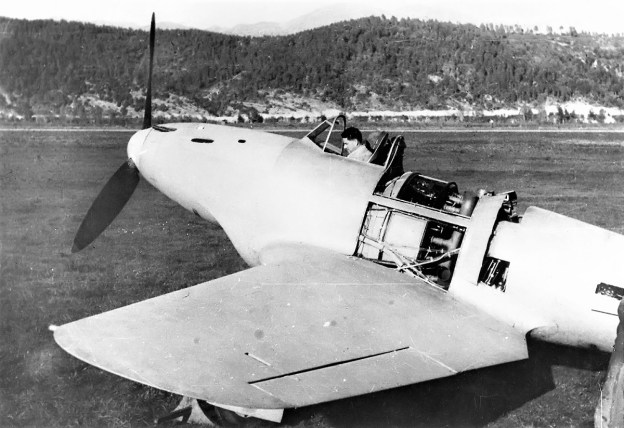
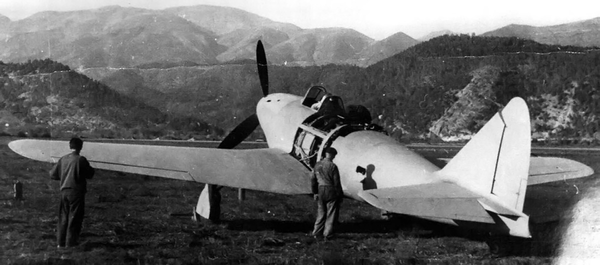
Like Lorraine, Hiro also produced W-18 engines. Hiro’s first W-18 engine was built in the early 1930s and used individual cylinders derived from the type used on the 12Fa Courlis / Type 91. While Hiro’s W-18 engine may have been inspired by the Lorraine 18K, the engine was not a copy of any Lorraine engine. Reportedly, Hiro’s first W-18 had a 60-degree bank angle between its cylinders. The engine did not enter production and was superseded in 1934 by the Type 94. The Type 94 replaced the earlier engine’s individual cylinders with monobloc cylinder banks and used a 40-degree angle between the banks. The W-18 engine had a 5.71 in (145 mm) bore and a 6.30 in (160 mm) stroke. The Type 94 displaced 2,902 cu in (47.6 L) and produced 900 hp (671 kW) at 2,000 rpm. The engine was 86 in (2.18 m) long, 44 in (1.11 m) wide, 43 in (1.10 m) tall, and weighed 1,631 lb (740 kg). Only a small number of Type 94 engines were produced, and its main application was the Hiro G2H long-range bomber, of which eight were built. The engine was found to be temperamental and unreliable in service.

The Hiro G2H1 bomber was the only application for the company’s Type 94 W-18 engine. The engine was problematic, and only eight G2H1s were built. Note the exhaust manifold for the center cylinder bank.
By the mid-1930s, the Navy’s aircraft engine development had been transferred from Hiro to the Yokosuka Naval Air Arsenal (Yokosuka). For a few years, the Navy and Yokosuka let aircraft engine manufacturers develop and produce engines rather than undertaking development on its own. However, around 1940, Yokosuka began development of a new W-18 aircraft engine, the YE2.
The Yokosuka YE2 was based on the Hiro Type 94 but incorporated many changes. The liquid-cooled YE2 had an aluminum, barrel-type crankcase, and its three aluminum, monobloc cylinder banks were attached by studs. The cylinder banks had an included angle of 40 degrees and used crossflow cylinder heads with the intake and exhaust ports on opposite sides of the head. All of the cylinder banks had the intake and exhaust ports on common sides and were interchangeable.
Each cylinder had two intake and two exhaust valves, all actuated by a single overhead camshaft. The camshaft for each cylinder bank was driven via a vertical shaft from an accessory section attached to the drive-end of the engine. The YE2 had a 5.71 in (145 mm) bore, 6.30 in (160 mm) stroke, and displaced 2,902 cu in (47.6 L). The YE2A, B, and C variants had a rated output of 1,600 hp. However, very little is known about these engines, and it is not clear if they were all built.

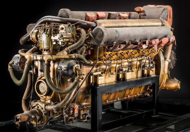
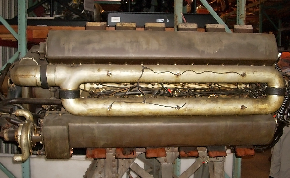
The Yokosuka YE2-series was developed from the Hiro Type 94. The YE2H was built in the early 1940s, but no applications for the engine have been found. Note the output shaft on the front of the engine that is bare of its extension shaft. The vertical fuel injection pump is just above the horizontally-mounted magnetos. (Smithsonian Air and Space Museum image)
The Yokosuka YE2H variant was developed around 1942 and given the Army-Navy designation [Ha-73]01. It is not clear how the YE2H differed from the earlier YE2 engine. The YE2H was intended for installation in an aircraft’s fuselage (or wing) in a pusher configuration. The rear-facing intake brought in air to the engine’s supercharger. Air from the supercharger was supplied to the cylinders at 12.6 psi (.87 bar) via three intake manifolds—one for each cylinder bank. A common pipe at the drive-end of the engine connected the three intake manifolds to equalize pressure. Fuel was then injected into the cylinders via the fuel injection pump driven at the drive-end of the engine. The two spark plugs per cylinder were fired by magnetos, located under the fuel injection pump. An extension shaft linked the engine to a remote gear reduction unit that turned the propeller at .60 times crankshaft speed.
The YE2H had a maximum output of 2,500 hp (1,864 kW) at 3,000 rpm. The engine had power ratings of 2,000 hp (1,491 kW) at 2,800 rpm at 4,921 ft (1,500 m) and 1,650 hp (1,230 kW) at 2,800 rpm at 26,247 ft (8,000 m). The YE2H was approximately 83 in (2.10 m) long, 37 in (.95 m) wide, and 39 in (1.00 m) tall. The engine weighed around 2,634 lb (1,195 kg). The YE2H was completed and run around March 1944, but development of the engine had tapered off in mid-1943. At that time, Yokosuka refocused on the YE3 engine, which was derived from the YE2H.

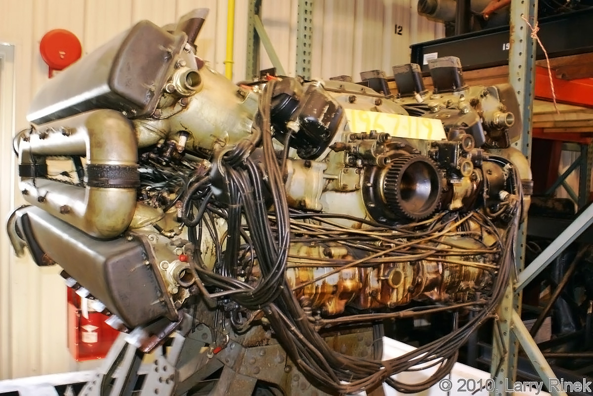
The YE2H’s rear-facing intake scoop (far left) indicates the engine was to be installed in a pusher configuration. Note the intake manifolds extending from the supercharger housing. (Smithsonian Air and Space Museum image)
Development of the Yokosuka YE3 started in the early 1940s. The engine possessed the same bore and stroke as the YE2, but the rest of the engine was redesigned. The YE3 was an X-24 engine with four banks of six cylinders. The left and right engine Vees had a 60-degree included angle between the cylinder banks, which gave the upper and lower Vees a 120-degree angle. The YE3’s single crankshaft was at the center of its large aluminum crankcase.
Each cylinder bank had dual overhead camshafts actuating the four valves in each cylinder. The camshafts were driven off the supercharger drive at the non-drive end of the engine. The supercharger delivered air to the cylinders via two loop manifolds—one located in each of the left and right engine Vees. Two fuel injection pumps provided fuel to the cylinders where it was fired by two spark plugs in each cylinder. The fuel injection pumps and magnetos were driven from the drive end of the engine. Exhaust was expelled from the upper and lower engine Vees. Like the YE2, the YE3 was designed for installation in an aircraft’s fuselage or wing, with an extension shaft connecting the engine to the remote propeller gear reduction.
The drive end of the Yoskosuka YE3B gives a good view of the engine’s X configuration. The fuel injection pumps are below the output shaft. (Larry Rinek image via the Aircraft Engine Historical Society)
The YE3A preceded the YE3B, but it is not clear if the YE3A was actually built. The Yokosuka YE3B was given the joint Army-Navy designation [Ha-74]01. The YE3B had a 5.71 in (145 mm) bore and a 6.30 in (160 mm) stroke. The engine displaced 3,870 cu in (63.4 L) and produced 2,500 hp (1,864 kW). The YE3B was rated at 2,150 hp (1,603 kW) at 6,562 ft (2,000 m) and 1,950 hp (1,454 kW) at 16,404 ft (5,000 m). The engine was approximately 79 in (2.00 m) long, 43 in (1.10 m) wide, and 28 in (.70 m) tall.
The YE3B was run by October 1943. The engine used a two-speed remote gear reduction that drove contra-rotating propellers. No real applications for the YE3B are known. However, the engine is often listed as the powerplant for the S-31 Kurowashi (Black Eagle), which was a purely speculative propaganda aircraft. The S-31 was designed as a heavy bomber, and its four YE3B engines were buried in its fuselage.
Side view of the YE3B illustrates the engine’s loop intake manifold. Spark plug leads and fuel injector lines can be seen in the Vee between the cylinder banks. Note the camshaft-driven water pump mounted on the end of the lower cylinder bank. (Tom Fey image)
A further development of the YE3-series was the YE3E. The YE3E was given the joint Army-Navy designation [Ha-74]11. The engine was similar to the earlier YE3-series except that it had two crankshafts. Some sources indicate the engine essentially consisted of two V-12s laid on their sides in a common crankcase with their crankshafts coupled to a common output shaft. The YE3E produced 3,200 hp (2,386 kW) and had power ratings of 2,650 hp (1,976 kW) at 4,921 ft (1,500 m) and 2,200 hp (1,641 kW) at 26,247 ft (8,000 m). The YE3E was approximately 79 in (2.00 m) long, 51 in (1.30 m) wide, and 39 in (1.00 m) tall. The engine was scheduled for completion in spring 1944, but no records have been found indicating it was finished.
A YE2H [Ha-73]01 W-18 engine and a YE3B [Ha-74]01 X-24 engine were captured by US forces after World War II. The engines were sent to Wright Field in Dayton Ohio for further examination. The United States Air Force eventually gave the YE2H and YE3B engines to the Smithsonian National Air and Space Museum, where they are currently in storage.

Detail view of the supercharger mounted to the end of the YE3B. Note the updraft inlet for the supercharger. Camshaft drives can be seen extending from the supercharger housing to the cylinder banks. (Tom Fey image)
Sources:
– Japanese Aero-Engines 1910–1945 by Mike Goodwin and Peter Starkings (2017)
– https://airandspace.si.edu/collection-objects/yokosuka-naval-air-arsenal-ye2h-ha-73-model-01-w-18-engine
– https://airandspace.si.edu/collection-objects/yokosuka-naval-air-arsenal-ye3b-ha-74-model-01-x-24-engine
– http://www.enginehistory.org/Piston/Japanese/japanese.shtml
– Japanese Secret Projects 1 by Edwin M. Dyer III (2009)