Category Archives: Between the Wars

Clerget 16 H Diesel Aircraft Engine

By William Pearce

In 1936, the French Air Ministry issued a specification for a flying boat able to carrying at least 40 passengers and 1,100 lb (500 kg) of cargo 3,725 miles (6,000 km) against a 37 mph (60 km/h) headwind. This large passenger aircraft was to be used on transatlantic service for both the northern and southern routes. In 1938, three projects were selected for prototype construction: the Potez-CAMS 161, the Lioré et Olivier H-49 (which became the SNCASE SE.200), and the Latécoère 631.

Clerget 16 H front

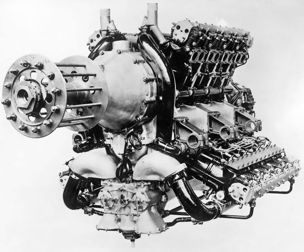
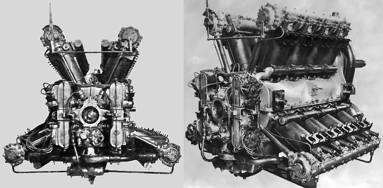
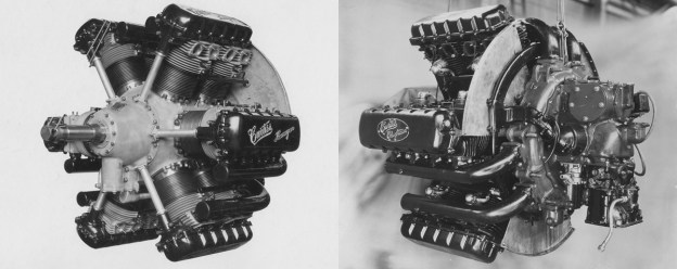
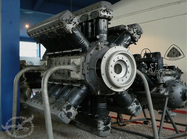
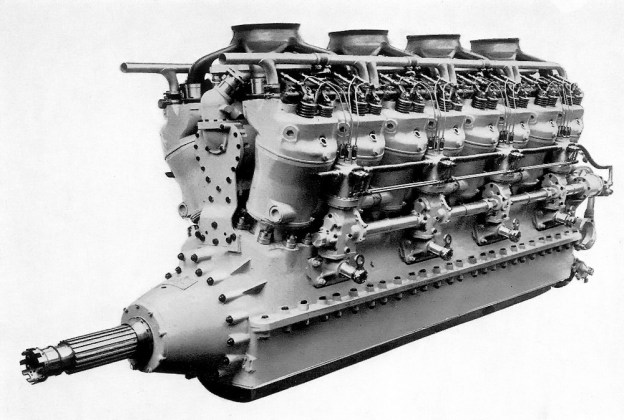
The 2,000 hp Clerget 16 H with four Rateau turbosuperchargers atop the engine. In between the cylinder banks is the camshaft housing.

The new transatlantic airliner would be a large aircraft, necessitating powerful engines. Pierre Clerget felt an entirely new engine was needed to power this aircraft. Clerget, an aircraft engine pioneer who had already designed and built a few diesel aircraft engines in his long career, decided to capitalize on the inherent safety and efficiency of a diesel engine. Diesel fuel offered an increase in fuel efficiency and was far less prone to accidental ignition, eliminating much of the fire risk common in early aviation.

Clerget spent much of 1937 designing the engine, and what emerged was a powerful V-16 diesel engine known as the Clerget 16 H. Because of its 16 H designation, the engine is often assumed to be of an H configuration. However, the “H” most likely represented “Huile,” a French word for oil, as diesel fuel is a type of fuel oil. The four-stroke 16 H engine was first displayed at the Paris Salon de l’Aviation (Air Show) in late 1938. The 16 H had a bore of 7.09 in (180 mm) and stroke of 7.87 in (200 mm). The engine’s total displacement was 4,969 cu in (81.43 L). The 16 cylinders were arranged at a 45 degree angle in two banks of eight cylinders. The compression ratio was 14 to 1. The direct drive engine had individual aluminum cylinders with a steel barrel for the aluminum piston. The exposed four valves per cylinder were actuated by roller rocker arms and short pushrods from the camshaft, that was situated in the Vee of the engine. The camshaft was driven from the crankshaft via a vertical drive shaft at the rear of the engine.

Clerget 16 H rear

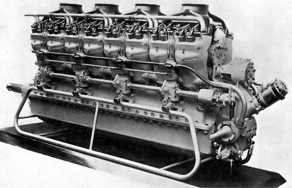
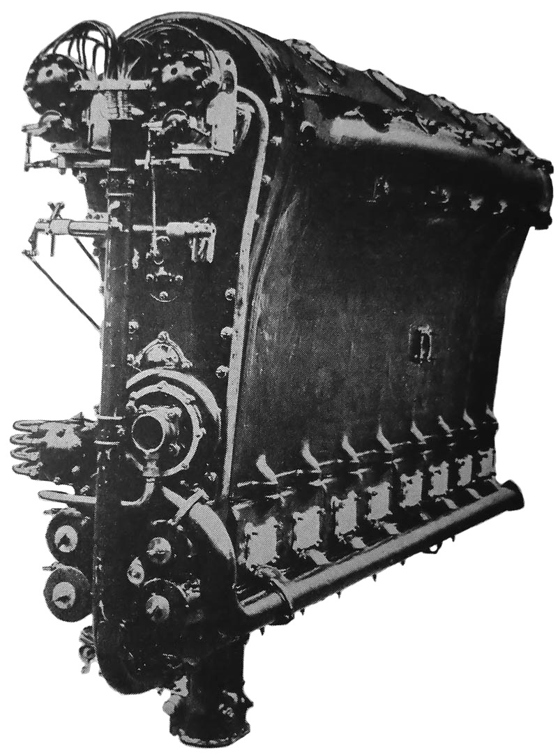
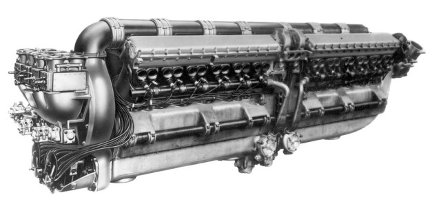
The diesel Clerget 16 H showing the fuel injection pumps along the side of the engine and various accessories at the rear of the engine.

Fuel injection for each cylinder was provided by two Clerget injection pumps and two Clerget hydraulically-operated injectors. Groups of four pump units (to supply two cylinders) were arranged on the outside of the engine, with a total of four such groups on each side. The pumps along each side of the engine were driven by a camshaft running at half-engine speed. One complete set of pumps could be shut off for operating the engine at low speeds. Fuel was injected into the cylinder at a maximum of 8,500 psi (586 bar).

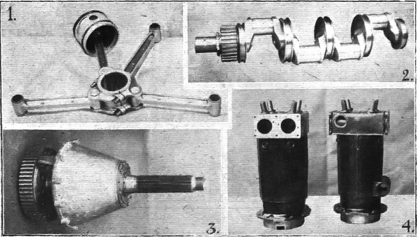
The 16 H used a two-piece aluminum crankcase. The single-piece crankshaft had eight throws and was supported by nine main bearings. Connecting rods were of the master and articulated rod type. Pressure lubrication was provided by a dry-sump system, and each bank of cylinders had its own water-cooling circulation system. Starting was achieved by an air-starter unit attached to the rear of the engine. The engine was 31.5 in (.8 m) wide, 49.2 in (1.25 m) tall, and 112.6 in (2.86 M) long. The 16 H weighed 3,750 lb (1,700 kg).

Four Rateau turbosuperchargers sat atop the Clerget 16 H engine. Each turbocharger served four cylinders (two on each side of the engine). The turbine spun by exhaust gases from the cylinders was at the top of the turbocharger, and the compressor that supplied air to the cylinders was at the bottom of the turbocharger. The turbochargers allowed the 16 H engine to maintain power up to 16,400 ft (5,000 m).

Clerget 16 H side

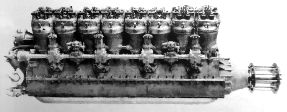
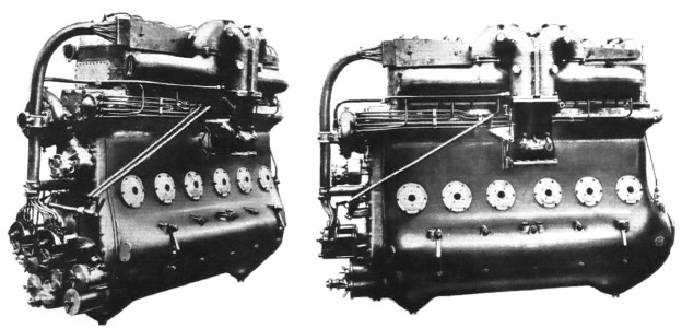
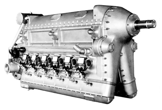
An early image of the Clerget 16 H without turbochargers.

First run on 17 May 1939, the 16 H could produce 1,500 hp (1,119 kW) without the turbochargers. With the turbochargers, the engine produced 2,000 hp (1,491 kW) at 2,200 rpm for takeoff and 1,600 hp (1,193 kW) at 1,800 rpm for continuous cruise. At cruise power, fuel consumption was 0.375 lb/hp/hr (228 g/kW/hr), and oil consumption was 0.020 lb/hp/hr (12 g/kW/hr).

With the German invasion of France on 10 May 1940, engine development and the transatlantic passenger seaplane were put on hold. The sole Clerget 16 H engine was destroyed during a bombing raid on Paris in 1940. There were some rumors that the engine was moved to Germany before the bombing, but nothing ever came of this. In October 1940, there was interest in building another 16 H, but no further development was undertaken. Pierre Clerget continued to work on other aircraft engine designs but was found dead in the Canal du Midi in Moissac, France on 22 June 1943—a sad end for a remarkable man. The cause of his death has never been explained.

The Germans restarted the transatlantic passenger seaplane program in March 1941, and an example of each prototype had been completed and flown by the end of 1942. These aircraft were subsequently destroyed in Allied bombing raids. After World War II, ten examples of the Latécoère 631 were built, each powered by six 1,600 hp (1,193 kW) Wright R-2600 engines. The aircraft entered service in 1947 but would not last long. After four of the Latécoère 631s had crashed in separate incidents, the remaining aircraft were banned from flying in 1955.

Latecoere 631 Lionel de Marmier

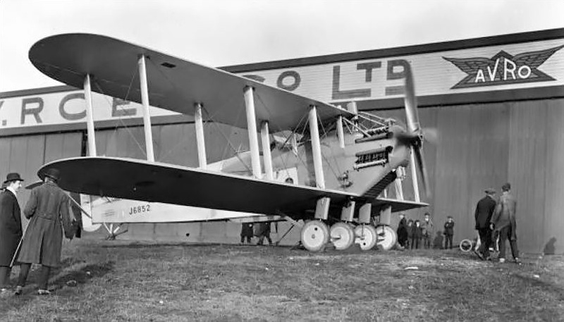
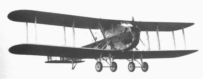
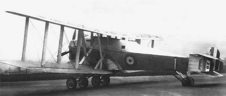
The inspiration for the Clerget 16 H: the transatlantic flying boat airliner. This Latécoère 631, named Lionel de Marmier after the French ace who served in WWI and WWII, disappeared over the South Atlantic with all 52 on board on 1 August 1948.

Sources:
Diesel Aviation Engines by Paul H. Wilkinson (1942)
Aircraft Engines of the World 1941 by Paul H. Wilkinson (1941)
Pierre Clerget: Un motoriste de génie by Gérard Hartmann (2004)
Flying Boats & Seaplanes by Stephane Nicolaou (1998)

Beardmore Cyclone, Typhoon, and Simoon Aircraft Engines

By William Pearce

In the early 1920s, William Beardmore & Company Ltd. began to design a series of high-power aircraft engines. One of the major problems facing aircraft designers at that time was converting the relatively high rpm of the engine to the low speed needed for a fixed-pitch propeller. Adding a propeller gear reduction increased the engine’s weight, complexity, and potential points of failure.

The 4207 cu in (68.9 L), straight-six Beardmore Cyclone.

The 4,207 cu in (68.9 L), straight-six Beardmore Cyclone.

Alan Chorlton, head of the Beardmore engine department, sought an alternative to the propeller reduction gear by having a relatively slow turning engine. In order for an engine to generate high power at low rpm, its cylinder must have a very large displacement.

Beardmore’s first high-power, low rpm aircraft engine designed by Chorlton was really two engines, the Cyclone and the Typhoon, whose development ran parallel. The Beardmore Cyclone was a water-cooled, straight-six engine with a 8.625 in (219 mm) bore and a 12 in (305 mm) stroke, giving it a total displacement of 4,207 cu in (68.9 L). The Beardmore Typhoon was essentially the same engine but in an inverted configuration. Almost all parts were interchangeable between the two engines.

The Beardmore Typhoon inverted engine.

The Beardmore Typhoon inverted engine.

Both the Cyclone and Typhoon used an aluminum crankcase that also formed the cylinder block. Thin steel Cylinder liners were inserted into the crankcase toward the crankshaft. The cylinder liners were supported by a flange toward the cylinder head and sealed by a ring toward the crankshaft. Each cylinder had its own detachable head. The four valves per cylinder were actuated via rockers and short pushrods from the single camshaft, which ran along the side of the engine just below the head. For the Cyclone, the camshaft was on the right side of the engine but, being rotated 180-degrees to the inverted position, the camshaft was on the left side of the Typhoon (both when viewed from the rear).

Two spark plugs were fitted to the top of each cylinder and fired by two Watford C6SM magnetos. The magnetos along with the water, oil, and fuel pumps were driven off the rear of the engines by a series of intermediate gears. Aluminum pistons with three compression rings and one oil-scrapper ring were used. The compression ratio was 5.25 to 1.

The Cyclone I was first run in 1922 and generated 700 hp (522 kW) at 1,220 rpm. Development continued, and by 1927, the Cyclone II was producing 850 hp (634 kW) at 1,350 rpm but could produce 950 hp (708 kW) at the same rpm with a larger carburetor. Fuel consumption was .48 lb/hp/hr (292 g/kW/h), and the engine weighed 2,150 lb (975 kg). The Cyclone was 80.3 in (2 m) long, 35 in (.9 m) wide, and 61.125 in (1.55 m) tall. Reportedly, only one Cyclone II was built, and it was sold to Heinkel Flugzeugwerke in Germany.

The Typhoon in the Avro 549C Aldershot IV during an engine run.

The Typhoon in the Avro 549C Aldershot IV during an engine run.

As already mentioned, the Typhoon was an inverted version of the Cyclone. The date the engine was first run is not clear, but the Typhoon was mentioned along with the Cyclone in a Beardmore brochure from 1924. The Typhoon I (some say Typhoon II) originally produced 800 hp (597 kW) at 1,350 rpm but was developed to 925 hp (690 kW) at the same rpm by 1926. Fuel consumption was .46 lb/hp/hr (280 g/kW/h), and the engine weighed 2,233 lb (1,013 kg). The Typhoon was 80.3 in (2 m) long, 38.5 in (.98 m) wide, and 59.3 in (1.5 m) tall. The Typhoon was installed in an Avro 549 Aldershot (J6852), replacing the Napier Cub engine. The Typhoon-powered aircraft, re-designated Avro 549C Aldershot IV, first flew on 10 January 1927. After a demonstration flight on 24 January 1927, pilot Bert Hinkler reported that the Typhoon engine was remarkably smooth.

The Beardmore Typhoon-powered Avro 549C Aldershot IV flown by Bert Hinkler during a flight demonstration on 24 January 1927. The inverted engine allows a good view from the cockpit.

The Beardmore Typhoon-powered Avro 549C Aldershot IV flown by Bert Hinkler during a flight demonstration on 24 January 1927.

Reportedly, this image is of the 750 hp (559 kW), semi-diesel Beardmore Typhoon.

Reportedly, this image is of the 750 hp (559 kW), compression ignition Beardmore Typhoon.

A low-speed, large displacement engine design was very suitable for compression ignition, and another Typhoon engine was built as a diesel. Some sources report this engine as the Typhoon I, while others simply refer to it as the Typhoon C.I. In addition, the engine was sometimes noted as a semi-diesel (surface ignition). However, the power output of 750 hp (559 kW) at 1,400 rpm suggests that it was a true compression ignition diesel. Regardless, the diesel Typhoon was dimensionally the same as the standard Typhoon. The engine was under development along with the Cyclone and standard Typhoon and is mentioned in some of the articles regarding those engines. Some sources state that this engine was installed in the Avro 549 Aldershot, but that does not seem to be the case. No evidence has been found that this engine ever flew. However, in 1924, the Air Ministry ordered nine compression ignition Typhoons to be used in the R101 airship under construction. By 1926, the Air Ministry felt the Typhoon had reached its development potential and changed the order to the Beardmore Tornado engine, then under development.

The 1,100 hp (820 kW), 5528 cu in (90.6 L), inverted, straight-eight, Beardmore Simoon aircraft engine.

The 1,100 hp (820 kW), 5,528 cu in (90.6 L), inverted, straight-eight, Beardmore Simoon aircraft engine.

The Beardmore Simoon engine was a further development of the standard Typhoon but was designed at the same time. Compared to the Typhoon, the Simoon’s bore was reduced to 8.5625 in (217.5 mm), but the stroke remained the same at 12 in (305 mm). However, two additional cylinders were added. This gave the inverted, straight- eight Simoon engine a total displacement of 5,528 cu in (90.6 L). The Simoon maintained the 5.25 to 1 compression ratio of the previous engines, and fuel consumption was .48 lb/hp/hr (292 g/kW/h). Normal output was 1,100 hp (820 kW) at 1,250 rpm, but 1,200 hp (895 kW) could be achieved at 1,350 rpm. The Simoon was 98 in (2.5 m) long, 37.6 in (.96 m) wide, and 72.6 in (1.84 m) tall. The Simoon’s height increase over the Cyclone and Typhoon was due to an additional sump protruding from the lower rear of the engine. The engine weighed 2,770 lb (1,256 kg). The Simoon was installed in the second Blackburn T.4 Cubaroo (N167), replacing a Napier Cub engine. The Simoon-powered Cubarro first flew early in 1927.

None of these large, low-speed, high power engines were a success, and only a small number were made.

Sources:
Aerosphere 1939 by Glenn Angle (1940)
Beardmore Aviation 1913-1930 by Charles Mac Kay (2012)
Jane’s All the World’s Aircraft 1928 by C.G. Grey (1928)
British Piston Aero Engines and their Aircraft by Alec Lumsden (1994/2003)
Avro Aircraft since 1908 by A J Jackson (1965/1990)
Blackburn Aircraft since 1909 by A J Jackson (1968/1989)
– “The Beardmore “Cyclone’ Aero Engine,” Flight (4 November 1926)
– “The Beardmore ‘Typhoon’ Mark I Engine,” Flight (27 January 1927)
– “The Beardmore Cyclone and Typhoon,” Flight (5 July 1928)
– “British Aero Engines,” Flight (29 May 1924)

Napier Cub E66 engine

Napier Cub (E66) – First 1,000 hp Aircraft Engine

By William Pearce

Early in 1919, Montague Napier, President of D. Napier & Son Ltd., decided that his company should focus entirely on aircraft engines. The company’s first aero-engine, the very successful 450 hp (336 kW) Lion, was in full production. Napier began to think about its replacement, or at least a complementary engine to diversify the product line. Napier approached the British Air Ministry with his new engine plans, and in September 1919, his company was awarded a contract to build six of these new engines at 10,000 GBP each.

Napier Cub E66 engine

The 1,000 hp (746 kW), 16-cylinder Napier Cub. Below the propeller gear reduction are the two duplex carburetors with an induction pipe leading to each cylinder bank.

What Napier had envisioned, and the Air Ministry purchased, was a large power plant of 1,000 hp (746 kW)—enough power for one engine to propel a large bomber aircraft. The engine was given the Napier designation E66 but was referred to as the Cub. Despite its diminutive name, the Cub was a much larger engine than the Lion. The Napier Cub was unlike any engine before or since.

The Napier Cub was a liquid-cooled, 16-cylinder engine with four banks of four cylinders arranged in an X configuration on an aluminum crankcase. The banks were not equally spaced: the angle between the top banks was 52.5 degrees; the banks on either side were angled at 90 degrees; and the angle between the bottom banks was 127.5 degrees. Reportedly, the engine was so arranged to relieve stress on the crankshaft and to ease the engine’s installation in aircraft.

Napier Cub E66 rear

The Napier Cub was the first aircraft engine to exceed 1,000 hp (746 kW). These rear views illustrate the cylinder bank angles, the four magnetos on the back of the engine, the housings for the camshaft drive, and the exposed valves.

The Cub used individual steel cylinders of a 6.25 in (158.75 mm) bore and 7.5 in (190.5 mm) stroke and were encased in separate welded-steel water jackets. The engine displaced 3,682 cu in (60.3 L). The Cub’s compression ratio was 5.3 to 1. The engine was 57 in (1.45 m) wide, 64.25 in (1.63 m) tall, 71.8125 in (1.9 m) long, and weighed 2,450 lb (1,111 kg).

Each of the Cub’s four connecting rods consisted of one master rod and three articulated rods. The pistons were aluminum and had two compression and two oil-scrapper rings. Each cylinder bank had a single overhead camshaft that was driven via a vertical shaft. The vertical shafts were at the rear of the engine and driven from the crankshaft. The overhead camshaft actuated four exposed valves per cylinder. The Cub had a 0.49 propeller gear reduction through the use of spur gears that raised the propeller shaft. The propeller shaft’s bearing arrangement allowed the engine to be used in either a tractor or pusher configuration.

Various parts of the Napier Cub: 1) Connecting rod assembly with one articulated rod attached to the bearing cap. 2) Four-throw crankshaft with roller bearings and spur reduction gear. 3) Propeller shaft with large spur reduction gear. 4) Two of the Cub's cylinders with the valve ports visible on the left cylinder and the water-cooling ports visible on the right cylinder.

Various parts of the Napier Cub: 1) connecting rod assembly with one articulated rod attached to the bearing cap; 2) four-throw crankshaft with roller bearings and spur reduction gear; 3) propeller shaft with large spur reduction gear; 4) two of the Cub’s cylinders with the valve ports visible on the left cylinder and the water-cooling ports visible on the right cylinder.

Dual ignition was provided by four magnetos geared off the rear of the engine. The single water circulation pump was located at the lower rear of the engine, was driven at 1.5 times camshaft speed, and had one outlet to supply each cylinder bank. Two duplex carburetors were located under the gear reduction at the front of the engine. Each carburetor fed two manifolds: one for an upper cylinder bank and the other for a lower bank.

The Napier Cub was first run in late 1920. It was the first aircraft engine to surpass the 1,000 hp (746 kW) mark, achieving 1,057 hp (788 kW) at 1,900 rpm during an early test. The second Cub engine built was first run in early 1922. That same year, the Cub was installed in a modified Avro 549 Aldershot I (J6852, the first prototype) and re-designated Aldershot II. The Aldershot was a long-range, heavy bomber bi-plane. It had a 68 ft (20.7m) wingspan, was 45 ft (13.7 m) long, and weighed around 6,200 lb (2,812 kg). The Cub-powered Aldershot II first flew on 15 December 1922, piloted by Bert Hinkler. The Aldershot II continued to fly for about four years before the Napier Cub was removed and another test engine (an 800 hp / 597 kW Beardmore Typhoon) was installed.

Napier Cub-powered Avro Aldershot II (J6852). This was the first Aldershot prototype, originally powered by a 650 hp Rolls-Royce Condor V-12 engine. To support the Cub, the aircraft had its main gear doubled to four wheels. After three years of Cub-power, the aircraft was re-engined with an 800 hp Beardmore Typhoon (straight-six semi-diesel).

Napier Cub-powered Avro Aldershot II (J6852). This was the first Aldershot prototype, originally powered by a 650 hp (485 kW) Rolls-Royce Condor V-12 engine. To support the Cub, the aircraft was strengthened and had its main gear doubled to four wheels. After two years of Cub-power, the aircraft was re-engined with an 800 hp (597 kW) Beardmore Typhoon.

A Napier Cub was also installed in both of the two Blackburn T.4 Cubaroos built. The Cubaroo was a long-range coastal defense bi-plane capable of carrying a 21-in (.533 m) torpedo or equivalent bomb load of 2,000 lb (907 kg). The aircraft had an 88 ft (26.8 m) wingspan, was 54 ft (16.5 m) long, and weighed 9,632 lb (4,396 kg) empty and 19,020 lb (8,709 kg) fully loaded. The Cubaroo was possibly the largest single-engine aircraft in its day. The first Cubaroo (N166) took to the air in the summer of 1924, piloted by P.W.S. ‘George’ Bulman. The aircraft was delivered to Martlesham Heath for flight trials in October 1924. Several engine failures were noted as well as a tendency for the engine to overheat during a high-power climb.

The second Cubaroo (N167) had a revised radiator and first flew in early 1925. Both Cubaroo aircraft were flown in various aviation displays and used for testing. N166 was damaged beyond repair in a landing accident on July 16, 1926. N167 continued to fly with Cub-power until 1927, when it was re-engined to test the 1,100 hp (820 kW) Beardmore Simoon.

The first Blackburn Cubaroo (N166) in flight. The 1,000 hp Cub seemed to be quite adequate for the aircraft.

The first Blackburn Cubaroo (N166) in flight. The 1,000 hp (746 kW) Cub seemed to be quite adequate for the large aircraft.

Another aircraft designed to use the Napier Cub was the Avro 556. With a wingspan over 95 ft (30 m), this aircraft was even larger than the Cubaroo, although intended for the same purpose of carrying a 21-in (.533 m) torpedo. This aircraft was never built; instead, the basic design was used for the twin Rolls-Royce Condor-powered Avro 557 Ava.

By June 1925, the concept of a single, large aircraft engine powering a very large aircraft fell to the wayside in favor of multiple engines, which gave some degree of enhanced safety. The Air Ministry lost its interest in the Napier Cub, and the world’s first 1,000 hp (746 kW) aircraft engine faded to obscurity.

The second Blackburn Cubaroo (N167) with the revised radiator to cool the Napier Cub.

The second Blackburn Cubaroo (N167) with the revised radiator to cool the Napier Cub.

Sources:
Aerosphere 1939 by Glenn Angle (1940)
Men and Machines by Wilson and Reader (1958)
By Precision Into Power by Alan Vessey (2007)
Avro Aircraft since 1908 by A J Jackson (1965/1990)
Blackburn Aircraft since 1909 by A J Jackson (1968/1989)
The British Bomber since 1914 by Francis Mason (1994)
British Flight Testing: Martlesham Heath 1920-1939 by Tim Mason (1993)

Curtiss H-1640 Chieftain Aircraft Engine

By William Pearce

In April 1926 the Curtiss Aeroplane and Motor Company initiated a design study for a 600 hp (447 kW), air-cooled aircraft engine. The engine was to have minimal frontal area while keeping its length as short as possible. Configurations that were considered but discarded were a 9-cylinder single-row radial, a 14-cylinder two-row radial, a 12-cylinder Vee, and a 16-cylinder X. The selected design was a rather unusual 12-cylinder engine that Curtiss referred to as a “hexagon” configuration. This engine was built as the Curtiss H-1640 Chieftain.

The Curtiss H-1640 Chieftain “hexagon” or “inline-radial” engine. The image on the left was taken in 1927; note “Curtiss Hexagon” is written on the valve covers. In front of each cylinder pair is the housing for the vertical shaft that drove the overhead camshafts. The image on the right was taken in 1932 and shows a more refined engine with “Curtiss Chieftain” written on the valve covers. Note the additional cooling fins surrounding the spark plugs. In both images, the baffle at the rear of each exhaust Vee forced cooling air into the intake Vee.

The Curtiss H-1640 was designed by Arthur Leak and Arthur Nutt. The Chieftain’s “hexagon” design was a combination of a radial and Vee engine. The intent was to combine the strengths of both engine configurations: the light and short features of a conventional radial with the narrow and high rpm (for the time) of a conventional Vee engine.

The Chieftain was arranged as if it were a 12-cylinder Vee engine cut into three sections, each being a four-cylinder Vee. The Vee engine sections were then positioned in a radial form 120 degrees apart (each cylinder bank being 60 degrees apart). The end result was a two-row, twelve-cylinder, inline radial engine. The H-1640 resembled a conventional radial engine except that the second cylinder row was directly behind the first.

An engine installation comparison of the air cooled Chieftain-powered XO-18 Falcon at left and a liquid-cooled D-12-powered Falcon at right. Note that while the Chieftain is a wider engine, it blends well with the fuselage and is shorter and not as tall as the Curtiss D-12.

Each four-cylinder Vee section had the cylinder exhaust ports on the inside of the Vee and the intake ports on the outside. Each inline cylinder pair had its own intake runner and dual-overhead camshafts that were enclosed in a common valve cover. The camshafts were driven via a single vertical shaft from the front of the engine. There were four valves per cylinder.

Cooling air was directed through each four-cylinder section’s exhaust Vee; here it met a baffle fitted to the rear of the engine and attached to the cowling. This baffle deflected the air and forced it to flow between the inline cylinders and behind the rear cylinder. The air then flowed into the intake Vee that was blocked off at the front. The air exited the cowling via louvers over the intake Vee.

The Curtiss O-1B Falcon that was redesignated XO-18 while it served as the test-bed for the Chieftain engine. Note the exposed valve covers and the exhaust stacks protruding through the engine cowling.

The pistons were aluminum and operated in steel cylinder barrels that were screwed and shrunk into cast aluminum cylinders with integral cooling fins. From U.S. patent 1,962,246 filed by Leak in 1931, it appears that the Chieftain’s connecting rods consisted of two halves that were bolted together. Each half was made up of one master rod and two articulating rods.

The H-1640 Chieftain had a bore of 5.625 in (143 mm) and a stroke of 5.5 in (140 mm), giving a total displacement of 1,640 cu in (26.9 L). The engine’s maximum diameter was 45.25 in (1.15 m). However, a special cowling was used, cut to allow the valve covers and exhaust stacks to protrude through, reducing the diameter of the cowling to 39 in (0.99 m). The engine was 52.3 in (1.33 m) long and weighed 900 lb (408 kg). The Chieftain had a 5.2 to 1 compression ratio and was rated at 600 hp (447 kW) at 2,200 rpm but developed 615 hp (459 kW). When the engine was pressed to 2,330 rpm, it produced 653 hp (487 kW). It was equipped with a centrifugal-type supercharger that allowed the engine to maintain sea-level power up to 12,000 ft (3,658 m). All Chieftain engines built were direct drive but geared versions had been planned. In addition, some design work on a four-row, 24-cylinder version of 1,200 hp (895 kW) had been done.

Side view of the Thomas-Morse XP-13 Viper with the Curtiss Chieftain engine and revised cowl. Not the louvers for the cooling air to exit the cowling.

Because the engine had an even number of cylinders per each row, a unique firing order was developed that alternated between the front and rear rows. When the engine was viewed from the rear, the cylinders were numbered starting with the cylinder bank at the 9 o’clock position and proceeding clockwise around the engine. The rear cylinder row had odd numbers, and the front cylinder row was even so that the rear cylinder of the cylinder bank at 9 o’clock was number 1 and the front was number 2. The firing order was initially 1, 10, 5, 7, 4, 11, 8, 3, 12, 2, 9, 6 but was later changed to 1, 10, 5, 2, 9, 11, 8, 3, 12, 7, 4, 6 in an effort to smooth out the engine.

The H-1640 Chieftain was first run in 1927 and flown in a modified Curtiss O-1B Falcon, redesignated XO-18, in April 1928. The Chieftain-powered test-bed aircraft was found to out-climb and have a higher ceiling than the standard liquid-cooled Curtiss D-12-powered Falcon. In addition, the top-speed of the two aircraft was the same, which was unheard of for that time period when liquid-cooled aircraft were faster than their air-cooled counterparts. However, the engine suffered cooling issues, and the aircraft was modified back to an O-1B in July 1930.

A comparison of the original cowling on the XP-13 at left and the updated cowling at right. The front of the cowling has been extended and angled out. The block-off plates in between the openings have been angled to funnel air into the enlarged openings.

Thomas-Morse also responded to the Army’s interest in using the Curtiss H-1640. The company’s Viper fighter prototype was built to use the Chieftain engine. This aircraft was tested at Wright Field in June 1929 and given the designation XP-13. Engine overheating was encountered, and a revised cowling was tried in an effort to provide adequate cooling for the H-1640. The new cowling had enlarged openings, and the blocked off sections were angled to force more air into the openings. However, over-heating persisted. The XP-13 was tested until September 1930, when a Pratt & Whitney R-1340C engine was installed and the aircraft redesignated XP-13A. Even though this engine was not as powerful, it was lighter and did not suffer the cooling issues present with the Chieftain. The XP-13A was found to be 15 mph (24 km/h) faster than the Chieftain-powered XP-13. Curtiss had planned to produce the Viper under the designation XP-14, but the H-1640 engine was lacking support so no aircraft were built.

Another Chieftain was installed in the Navy’s second Curtiss XF8C-1 prototype in 1930. The H-1640-powered aircraft was known as the Curtiss XOC3. It too suffered from engine over-heating. The Chieftain engine remained installed in the XOC3 until the aircraft was removed from the Navy’s inventory in April 1932.

Detail view of the revised cowling on the Chieftain-powered Thomas-Morse XP-13. The image on the left illustrates the angle of the block-off plates. Note the six, instead of eight, exhaust stacks of the upper cylinders. The last two stacks are combined and exit from a single stack aft of the cowling.

In October 1928, the Army ordered three Curtiss P-6 Hawk aircraft to be powered by the H-1640 engine and designated them XP-11. However, shortly after the order was placed, the engine’s cooling trouble became known and the engine’s development ceased. The aircraft were never built with the Chieftain engine.

A total of eight H-1640 engines were made with six going to the Air Corps and two to the Navy. While the Chieftain’s design may have been problematic, the event that directly led to its lack of support and ultimate abandonment was the merger of Curtiss Aeroplane and Motor Company with Wright Aeronautical in July 1929. After the merger, the liquid-cooled engines were provided by Curtiss and the air-cooled engines from Wright. There was no longer a need for the Chieftain, an air-cooled engine of rather dubious design. However, the concept of a hexagonal engine would be revisited with the Wright H-2120, and other hexagonal engines include the SNCM 137, the Junkers Jumo 222, and the Dobrynin series of aircraft engines..

Reportedly, at least one Curtiss H-1640 Chieftain survives and is in storage at the National Air and Space Museum’s Garber Facility in Silver Hill, Maryland.

The second Curtiss XF8C-1 re-engined with the H-1640 Chieftain and redesignated XOC3.

Sources:
Modern Aviation Engines, Volume 2 by Victor Page (1929)
– “The Curtiss ‘Chieftain’ Engine,” Flight by Erik Hildeshim (14 June 1928)
Dyke’s Aircraft Engine Instructor by A.L. Dyke (1929)
Aerosphere 1939 by Glenn Angle (1940)
Curtiss Aircraft 1907-1947 by Peter Bowers (1979/1987)
American Combat Planes of the 20th Century by Ray Wagner (2004)
Fighters of the United States Air Force by Dorr and Donald (1990)
General Dynamics Aircraft and their Predecessors by John Wegg (1990)

FIAT AS.6 Aircraft Engine (for the MC.72)

By William Pearce

For the 1929 Schneider Trophy Contest, Italy fielded a number of different aircraft and engine combinations. The end result was that none of their entries were developed enough be victorious, and Britain won the contest for the second time in a row. If the British were to win the competition in 1931, the Schneider Contest would be over, and Britain would retain permanent possession of the Schneider Trophy.

Side view of the FIAT AS.6 illustrating the engine’s length. In the middle of the engine at bottom, two water pumps can clearly be seen with coolant lines feeding the individual cylinders. Right behind the propeller hubs, one of the front engine section’s magnetos can be seen. The small pipes leading from the middle of the engine toward the rear engine section and from right behind the front engine section’s cylinder bank and toward the front engine are for the air starter.

To prevent a British victory in 1931, Italy focused on developing one aircraft and one powerplant for its Schneider efforts. Macchi Aeronautica was chosen to develop the airframe, and with the design talents of Mario Castoldi, the Macchi-Castoldi 72 (MC.72) was born. FIAT was tasked with developing an engine to power the MC.72 and defeat the British. Time was short for FIAT because the MC.72 would be designed around the engine.

As the FIAT engine team, led by Tranquillo Zerbi, began to develop a new powerplant, they quickly realized that there was not enough time to start from scratch; the engine that was to power the MC.72 would have to start from an existing engine. FIAT’s best powerplant at the time was the 1,000 hp (746 kW) AS.5 (Aviazione Spinto) V-12 engine. This engine was used in one of Italy’s 1929 Schneider racers, the FIAT C.29. The Italian team knew the engine would need at least 2,300 hp (1,715 kW) to win the 1931 Schneider Contest and began developing a supercharger, increasing the engine’s compression, and incorporating other enhancements to attempt to achieve the desired power. But even early on, Zerbi knew the AS.5 engine could not develop the power needed to defeat the British.

While working on the enhanced AS.5, a proposal was made to mount two AS.5 engines back-to-back, creating a V-24 engine. FIAT moved forward with the concept and called it the AS.6, but it was not as simple as bolting two AS.5 engines together. The AS.5 engine sections were not coupled together. They shared a common magnesium crankcase and an induction manifold, and there was only one throttle linkage. Everything else (the ignition, coolant, and oil systems) was independent for each engine section.

Rear view of the FIAT AS.6 showing the two four-barrel carburetors feeding the supercharger. Directly below the supercharger are fuel pumps and the two magnetos for the rear engine section.

A 0.60 gear reduction for the propellers would be driven from the back of each AS.5 engine section (middle of the V-24 power plant). A drive shaft would be taken from the gear reduction of each engine. These drive shafts would travel through the Vee of the front engine and to the nose of the aircraft.  The rear engine drove a 69.96 in (1.77 m) shaft inside the front engine’s 52.52 in (1.334 m) shaft. Via the drive shaft, each engine drove one pair of propellers that together made a coaxial contra-rotating unit; the front engine drove the rear propeller, and the rear engine drove the front propeller. Coaxial contra-rotating propellers allowed for a blade short enough to avoid sea spray and also cancelled out the torque of the engine.

The rear engine section powered a supercharger that supplied 6.5 psi (0.45 bar) of air to both engine sections through a manifold approximately 88.58 in (2.25 m) long. The supercharger took 250 hp (186 kW) to run and spun at 17,000 rpm. The propeller pitch was ground adjustable. The front and rear propellers were adjusted to different pitches to compensate for the supercharger’s drain on the second engine section (front propeller) and efficiency differences between the first and second set of blades. The metal propellers were 8.5 ft (2.59 m) in diameter.

A detailed view inside the FIAT AS.6. The propeller gear reduction and drive shafts can clearly be seen. Note the individual cylinders on the far side of the engine and how the two crankcase sections are joined in the middle.

The FIAT AS.6 was a liquid-cooled, 60-degree, V-24 engine. It used individual steel cylinders, each with a 5.4 in (138 mm) bore and 5.5 in (140 mm) stroke, giving a total displacement of 3,067 cu in (50.256 L). The engine had a maximum compression ratio of 7 to 1. Four valves per cylinder were actuated by dual-overhead camshafts. The AS.6 was 132.48 in (3.365 m) long, 27.64 in (0.702 m) wide, 38.43 in (0.976 m) tall, and weighed 2,050 lb (930 kg). The engine was started by compressed air fed from a distribution pump located on the gear reduction housing. The rear engine section was started first.

Each inboard camshaft was driven from a gear parallel to and smaller than the propeller reduction gear. The outboard camshaft was geared to the inboard camshaft. Oil and water pumps were gear driven from the crankshaft. Each bank of each engine section had its own water pump. Ignition for each engine section was provided by two magnetos. The rear engine section’s magnetos were crankshaft driven and located below the supercharger. The front engine section’s magnetos were located on top of the engine, near the propellers, and driven from the outer (front engine’s) propeller shaft. Each cylinder had two spark plugs installed perpendicular to its axis: one located below the intake valves and the other below the exhaust valves.

Sectional view of the FIAT AS.6 illustrating the propeller drive shafts. Note the gear drive for the camshafts at top, the oil and water pumps at bottom, the front engine section’s magnetos at front, and the supercharger and rear engine section’s magnetos at rear.

During development, the AS.6 engine suffered many technical difficulties. Issues were encountered with spark plugs, ignition, coolant flow, fuel metering, induction, exhaust valves, connecting rods, and supercharger drive, to name a few. Much time was spent to resolve the issues. By April 1931, the engine completed a one hour run, producing 2,300 hp (1,715 kW).

The AS.6 engine was installed in the first of five MC.72 aircraft (MM 177 to MM 181), and flight trials began in the summer of 1931. Almost immediately, a new and very dangerous problem was discovered: while in flight, the engine would backfire at high power and high speed. The cause of this issue was a bit of a mystery because the engine ran perfectly on the ground but not during flight. Even with the engine’s difficulties, the aircraft had attained a speed of 375 mph (604 km/h). To demonstrate the backfire phenomenon, Capt. Giovanni Monti flew the MC.72 (MM 178) for FIAT and Macchi engineers on 2 August 1931. Sadly, a backfire ignited the volatile air/fuel mixture in the long induction manifold and caused it to explode. The MC.72 crashed into Lake Garda. Monti was killed in the crash.

FIAT AS.6 engine being test run in a MC.72.

With the Schneider Contest one month away and the cause of the backfiring still unknown, the decision was made to withdrawal the AS.6-powered MC.72 from the race. The British would make an uncontested flight for the Schneider Trophy and retain it permanently. But the Italians had decided to make an attempt on the absolute world speed record on 13 September 1931, the same day as the Schneider race. On 10 September, Lt. Stanislao Bellini was making a practice run to exceed 394 mph (634 km/h), the fastest the MC.72 had flown, when the aircraft (MM 180) flew straight into rising terrain. Debris found some distance from the impact site indicated that there had been an in-flight fire or explosion. Subsequently, the MC.72 was withdrawn from flight status.

The vision of what the AS.6 and MC.72 could have been continued to stir in the minds of various officials, and a new record attempt was planned. Believing the backfire issue was fuel related, the Italians wanted the help of Rod Banks: the Britain who developed the special fuel used for Rolls-Royce’s R Schneider engine. Banks was closely associated with the British Schneider effort but was not employed by Rolls-Royce or Supermarine. In 1932, the British sent Banks to see what could be done to improve the AS.6 engine.

Rear view of a preserved FIAT AS.6 engine at the Centro Storico Fiat in Turin, Italy. (Gianni image)

Banks arrived to find the AS.6 engine producing 2,400 hp (1,790 kW), but not reliably. A special sprint version of the engine had produced 2,850 hp (2,125 kW), but only for one minute. One of the issues Banks discovered was that the Italians had not fully accounted for the ram effect of having air forced into the induction by the forward speed of the aircraft. The AS.6 ran well on the ground, but the 400+ mph (640+ km/h) air being rammed into the intake caused a lean condition. This lean condition led to a backfire that ignited the air/fuel mixture in the long induction.

Banks knew how Rolls-Royce had dealt with this issue. Rolls-Royce had used a Kestrel engine to run a blower that supplied ram air for the R engine being tested. Banks had the Italians use a similar set-up that provided ram air at 435 mph (700 km/h) into the AS.6’s intake. The AS.6 engine was tuned under these conditions and no longer backfired. The sprint engine was able to produce 2,850 hp (2,125 kW) for an hour.

Warrant Officer Francesco Agello and the FIAT AS.6-powered MC.72 after setting the 3 km absolute world speed record at 440.682 mph (709.209 km/h) on October 23, 1934.

Late in 1932, the MC.72 took to the air once more; the AS.6 engine now produced a reliable 2,400 hp (1,790 kW). On 10 April 1933, Warrant Officer Francesco Agello set a 3 km absolute world speed record at 423.824 mph (682.078 km/h) in MM 177. On 8 October 1933, LtCol. Guglielmo Cassinelli captured the 100 km speed record at 391.072 mph (629.370 km/h). On 21 October, Capt. Pietro Scapinelli won the Blériot Cup in MM 179 for flying in excess of 600 km/h for over half an hour. His actual speed over the 30 minute run was 384.799 mph (619.274 km/h).

A year later, an AS.6 sprint engine was installed in the MC.72 (MM 181). This engine produced 3,100 hp (2,312 kW) at 3,300 rpm; 11.5 psi (0.79 bar) of boost was provided by the supercharger spinning at 19,000 rpm. On 23 October 1934, Agello was again at the controls and upped the 3 km record to 440.682 mph (709.209 km/h)—Agello was the fastest man on earth. This speed has never been surpassed by a piston-powered seaplane.

The record-setting MC.72 (MM 181) and an AS.6 engine are on display in the Museo Storico dell’Aeronautica Militare in Vigna di Valle, Italy. Another AS.6 engine is on display at the Centro Storico Fiat (Fiat Historic Center) in Turin, Italy.

The FIAT AS.6 displayed alongside the MC.72 (MM 181) at the Museo Storico dell’Aeronautica Militare in Vigna di Valle, Italy.

Sources:
The Schneider Trophy Story by Edward Eves (2001)
Schneider Trophy Seaplanes and Flying Boats by Ralph Pegram (2012)
Schneider Trophy Aircraft 1913-1931 by Derek James (1981)
Schneider Trophy Racers by Robert Hirsch (1993)
Jane’s All the World’s Aircraft 1935 by Grey and Bridgman (1935)
Italian High-Speed Airplane Engines NACA Technical Memorandum No. 944 by C. F. Bona (1935/1940) 17.7mb pdf
Technical Aspects of the Schneider Trophy and the World Speed Record for Seaplanes by Ermanno Bazzocchi (1971)
Idrocorsa Macchi by Apostolo and Cattaneo (2007)
I Kept No Diary by F.R. Banks (1978)

Argus As 5 Aircraft Engine

By William Pearce

Following World War I, the Treaty of Versailles severely limited aircraft production in Germany; military aircraft could not be built or developed. Germany created the Department of Aviation within the Ministry of Transportation to oversee commercial aircraft. The Department of Aviation initiated development of a large, powerful engine to solely provide power for an equally large aircraft. This led to the Argus As 5—the company’s first post-World War I engine project.

The 24-cylinder Argus As 5. (Polish Aviation Museum Krakow image)

The Argus As 5 was a liquid-cooled, 24-cylinder engine with six banks of four cylinders. The cylinders were arranged in a double-W, or double broad arrow fashion. The top and bottom banks of cylinders had 45-degrees of separation from the bank on either side. The top set of three cylinder banks was separated by 90-degrees from the bottom set of three cylinder banks. All cylinders used a common crankshaft with a master and articulated connecting rod arrangement.

The As 5 had bore of 6.30 in (160 mm) and stroke of 7.68 in (195 mm). Total displacement was 5,742 cu in (94.1 L) and the engine had a compression ratio of 5.6 to 1. The As 5 developed 1,500 hp (1,120 kW) at 1,800 rpm and weighed 2,425 lb (1,100 kg). The As 5 used individual cylinders with welded steel water jackets. All the cylinders for a single bank shared a common aluminum head. Valves were actuated by a single overhead camshaft. The aluminum crankcase was separated into a top and bottom half.

Close-up view of the top three cylinder banks of the Argus As 5. (Stanislaw Guzik image)

After a few engine runs, the idea to power a large aircraft with a single large engine progressed no further, and the As 5 never took flight. Three Argus As 5 engines were built between 1924 and 1927. Development was abandoned partly because no aircraft could handle the engine’s immense size and weight. In addition, the German Ministry of Transportation decided that two smaller engines were more practical than a single large engine.

One of the three engines built still exists and is on display at the Polish Aviation Museum Krakow. The Argus As 5 is the largest engine in the museum’s aircraft engine collection.

Left view of the 1,500 hp Argus As 5. (Štepán Obrovský / Zdeněk Kussior image)

Sources:
Argus – Flugmotoren und Mehr by Wulf Kisselmann (2012)
Flugmotoren und Strahltriebwerke by von Gersdorff, Schubert, and Ebert (2007)
Kolben-Flugmotoren by Hans Giger (1986)
http://www.muzeumlotnictwa.pl/zbiory_sz.php?ido=115&w=a
http://www.enginehistory.org/Museums/EasternEurope/EasternEurope.shtml

Deschamps V 3050 Diesel Aircraft Engine

By William Pearce

In the late 1920s, Desire Joseph Deschamps moved forward with his vision of an inverted, two-stroke, high-speed, diesel aircraft engine. Deschamps had immigrated to the United States from Belgium, where he had worked for the Minerva Company. Reportedly, Deschamps had a hand in designing Minerva’s first aircraft engine, which was also the first aircraft engine to incorporate Knight sleeve-valves (two sleeves).

Deschamps rotary valve as outlined in U.S. patent 2,064,196. On the left is a transverse sectional view of the cylinder with the rotary valve below (inverted engine) and feeding to the combustion chamber. On the right is a side view of the rotary valve for two cylinders revealing the various ports in the valve.

Working out of St. Louis, Missouri, Deschamps began the design of an inverted, liquid-cooled, straight six-cylinder, diesel aircraft engine. Outlined in U.S. patent 2,064,196, what was unique about this diesel engine was the use of a rotary sleeve valve. This rotary valve was essentially a cylindrical tube that ran the length of the engine below (inverted engine) the combustion chamber. Induction air flowed through the tube that rotated at half crankshaft speed. As the tube rotated, ports in the tube aligned with a port to the cylinder, allowing fresh air to force the exhaust gases out of the cylinder and provide air for the next combustion cycle. The exhaust ports were around the cylinder wall and covered/uncovered by the piston.

From all accounts, the rotary valve engine was never built. A more conventional valve arrangement was adopted, utilizing poppet-valves, rather than the rotary valve, for the intake . A two-cylinder test engine was built and run in the early 1930s. The test engine engine developed 174 hp (130 kW) at 1,600 rpm. This two-cylinder engine was expressly for the development of the Deschamps inverted V-12 diesel, having the same bore, stroke, and general configuration of the larger engine to come.

Deschamps V 3050 inverted V-12 aircraft diesel engine of 1934.

The Deschamps V 3050 was an inverted, 12-cylinder, diesel aircraft engine of all aluminum construction. The engine was built by the Lambert Engine and Machine Company in Moline, Illinois and completed in 1934. The cylinder banks were arranged in a 30-degree Vee to minimize the engine’s frontal area. With a 6.0 in (152 mm) bore and 9.0 in (229 mm) stroke, the engine had a total displacement of 3,053 cu in (50.0 L). The liquid-cooled, direct drive engine produced 1,200 hp (895 kW) at 1,600 rpm for takeoff and 950 hp (708 kW) at 1,500 rpm for cruise. Fuel consumption was 0.41 lb/hp/hr (249 g/kW/h). When built, it was one of the largest and most powerful diesel aircraft engines in the world.

The compression ratio of the V 3050 was 16 to 1, and air was forced into the cylinders by two gear-driven GE superchargers. The centrifugal superchargers were driven at 13.5 times crankshaft speed (21,600 rpm) and provided air at 12 psi (0.83 bar). Cylinder scavenging for the two-stroke cycle required eight psi, leaving four psi for boost. A small portion of the air entering the superchargers was taken from the crankcase to provide ample ventilation and burn away any fuel vapors. Sea-level power could be maintained to an altitude of 10,000 ft (3,048 m).

Each bank of cylinders had an intake manifold on the inside of the Vee to deliver air from the superchargers to the cylinders. The compressed air entered each cylinder via two poppet valves actuated simultaneously by an overhead camshaft driven at crankshaft speed.

Rear view for the Deschamps diesel highlighting the two GE superchargers. The glow plugs are also visible on the right cylinder bank.

A ring of 12 exhaust ports was located in the cylinder wall and exposed by the piston. To prevent excessive oil consumption and exhaust smoke, a small horizontal groove was cut in the cylinder wall just below each of the 12 exhaust ports. The grooves in the cylinder liner aligned with an annular groove in the cylinder casing wall. The annular grooves for all 12 cylinders were connected to a vacuum pump that scavenged oil from the pistons. The amount of oil stripped from the pistons was controlled by the amount of vacuum.

The superchargers and camshafts were driven from the crankshaft via separate vertical shafts with bevel gears. A Lanchester type torsional vibration damper was incorporated on the rear of the crankshaft to protect the gear drives. The damper was combined with a torque limiter clutch that would slip momentarily under sudden changes in torque.

Each bank of cylinders had independent intake delivery, exhaust, liquid-cooling connections, oil connections, oil and fuel pumps, and fuel injectors. In theory, each bank could be operated independently of the other bank, sharing only a common crankshaft. At 1,600 rpm, oil was circulated at 80–100 psi (5.5–6.9 bar) while coolant circulation was at 230 gpm (871 l/m).

Sectional view of the Deschamps V 3050 diesel with the glow plug detailed on the lower left.

Fuel was injected directly into each cylinder via two Deschamps-designed (U.S. patent 2,020,302) fuel injectors operating at 3,500 psi (241.3 bar). The two injectors per cylinder alternated supplying fuel into the cylinder, each firing every-other compression stroke. For slow rpm operation, one injector was shut off, essentially making the engine a four-stroke. This kept the engine running smoothly and the cylinders warm for instant application of more power. One fuel pump for each engine bank was used and supplied fuel at 15 psi (1.0 bar) with a maximum flow of 150 gph (9.4 l/m).

The engine was air-started by a compressor charged to 850 psi (58.6 bar). For staring the engine in cold weather, glow plugs were provided in the right cylinder bank while the left bank’s intake valves were kept open with the fuel shut off. A reversing gear could be fitted for utilizing the engine in airships. The V 3050 was 26.5 in (0.67 m) wide, 49.5 in (1.26 m) tall, and 99 in (2.52 m) long. It weighed 2,400 lb (1,089 kg) with all accessories, giving it 2.0 lb/hp (1.2 kg/kW).

After completing the engine, no funds remained for testing. Deschamps met with the Army Air Corps Power Plant Laboratory in June 1934, but it seems no further testing was done on the engine. Deschamps went on to work for various aviation corporations, patenting a number of fuel injectors and pumps along the way. Amazingly, the Deschamps V 3050 diesel engine survives and is in storage at the National Air and Space Museum’s Garber Facility in Silver Hill, Maryland.

Deschamps Diesel in storage at the National Air and Space Museum’s Garber Facility in Silver Hill, Maryland. (Fred van der Horst image via the Aircraft Engine Historical Society)

Sources:
Aircraft Diesels by Paul H. Wilkinson (1940)
Aerosphere 1939 by Glenn Angle (1940)
Diesel Aviation Engines by Paul H. Wilkinson (1942)
Jane’s All the World’s Aircraft 1934 by C. G. Grey (1934)
– “A 1,200 H.P. Diesel Engine.” Flight. May 24, 1934
– “Internal Combustion Engine” U.S. Patent 2,064,196 by Desire J. Deschamps (1930) pdf