By William Pearce
With the intention of creating a high speed light bomber, Viktor Bolkhovitinov designed what is commonly referred to as the Bolkhovitinov S or Sparka. During flight trials the Soviet Air Force (VVS) referred to the aircraft as S-2M-103, for skorostnoy (high speed) with two M-103 engines; however, a number of other designations have been applied over the years. The common “Sparka” designation means twin—because the aircraft had two engines mounted in tandem. Other designations are BBS-1 for blizhniy bombardirovshchik skorostnoy (short range bomber, high-speed), BB for blizhniy bombardovshchik (short range bomber), and LB-S for lyohkiy bombardirovshchik-sparka (light bomber-paired).

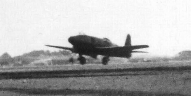
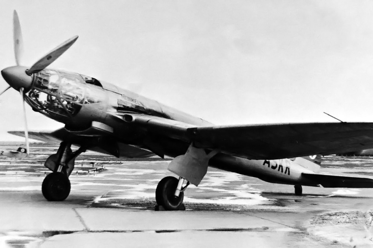
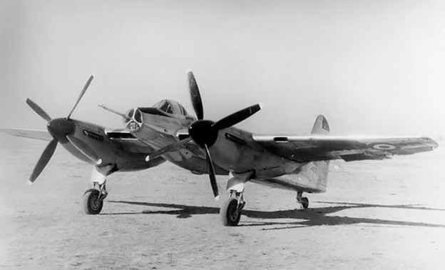
A good view of the twin-engine Bolkhovitinov Sparka. Note the plexiglass glazing for the bombardier’s downward view.
The Sparka was a low-wing aircraft of all-aluminum construction with stressed skin. The aircraft had a twin fin tail to increase the rear gunner’s field of fire. The undercarriage was fully retractable; the main gear retracted toward the rear, and the wheels rotated 90 degrees to lie flat within the wings. The pilot and navigator/bombardier/gunner sat in tandem under a long canopy. Between the pilot and second crew member was a small bomb bay for 882 lb (400 kg) of bombs. A plexiglass section on the bottom of the aircraft just aft of the bomb bay provided the bombardier a view of the ground. The aircraft was 43 ft 4 in (13.2 m) long and had a relatively short wingspan of 37 ft 4 in (11.38 m). The Sparka weighed 12,460 lb (5,652 kg).
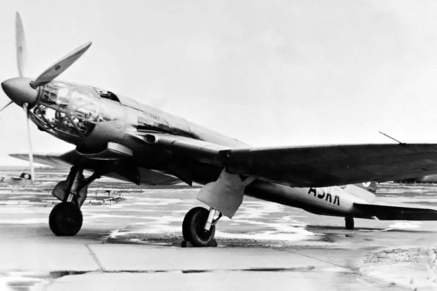
The Sparka was powered by two Klimov M-103A engines positioned in tandem in the aircraft’s nose. This coupled engine package was designated M-103SP. Each engine drove half of the aircraft’s six-blade, coaxial contra-rotating propeller unit. This engine and propeller arrangement was similar to the FIAT AS.6 installed in the Italian MC.72 and the Hispano-Suiza 12Y installed in the French Arsenal VB 10. With this engine arrangement, the front engine drove the rear propeller, and the rear engine drove the front propeller via a drive shaft that ran through the Vee of the front engine.

Schematic of the paired Klimov M-103 engines installed in the Bolkhovitinov Sparka with the rear engine’s drive shaft passing through the Vee of the front engine.
The Klimov M-103 engine was derived from the M-100, which was a licensed copy of the Hispano-Suiza 12Ybrs. The M-103SP had a 5.83 in (148 mm) bore and a 6.69 in (170 mm) stroke. Total displacement was 2,142 cu in (35.09 L). The engine produced 960 hp (716 kW). A radiator was installed in a large duct just below the rear engine, and it cooled both of the Sparka’s engines.
Bolkhovitinov started design work on the Sparka in 1937, and prototype construction began in July 1938. The aircraft made its first flight in January 1940 (some say late 1939) with B. N. Kudrin at the controls. VVS testing took place from March through July 1940. The Sparka showed good speed, reaching 354 mph (570 km/h). However, the takeoff run was excessive, landing speeds were high, and visibility over the nose was impaired. In addition, some trouble was encountered with the rear engine’s propeller drive shaft breaking due to excessive vibrations. Even so, the aircraft received a positive assessment, noting that the installation of the tandem engines eliminated a considerable amount of drag over two separate nacelles.

Engine bay view of the two Klimov M-103 engines.
A new wing was designed with a NACA-230 airfoil section to improve takeoff and landing performance. The aircraft was tested with this new wing from September to December 1940, and it did improve the aircraft’s takeoff and landing characteristics.
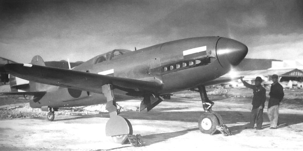
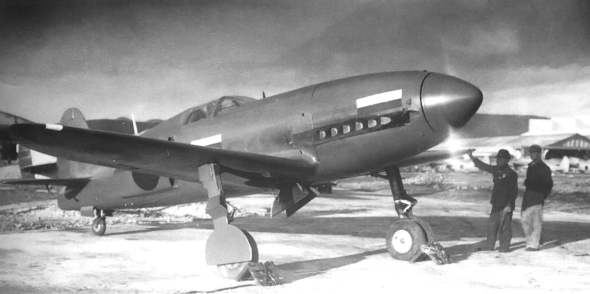
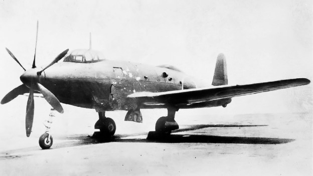
The Sparka was reconfigured for a single 1,050 hp (783 kW) Klimov M-105P (some say 103P) engine, which was installed in the forward engine bay. The M-105P was a development of the M-103P and could be fitted with a cannon in the engine’s Vee to fire through the propeller hub. The M-105P retained the bore and stroke of the earlier M-103P (and M-103SP) engine. The aircraft was tested on skis in early 1942 but was underpowered with the single M-105P, attaining a top speed of only 249 mph (400 km/h).

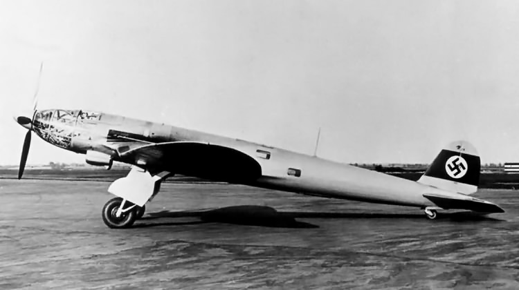
In this side view, the glazing on the bottom of the Sparka can clearly be seen.
Some say the single engine version was really a separate aircraft (known as S-1) that flew in January 1940 to test the airframe configuration. This seems unlikely because of the time frame involved. The twin-engine Sparka (S-2) would have been nearly complete by the time the single engine airframe test ship first took to the air, making major changes impossible and minor changes difficult. If the airframe test ship had issues, there would not have been enough time for any changes to be made before the official trials took place in March 1940. Not to mention that adding the power and weight of another engine would change the aircraft’s flight dynamics considerably.

The single-engined Bolkhovitinov S on skis.
Regardless, development on the Sparka was abandoned in mid-1941, partially a result of the German invasion. However, further studies were made on the feasibility of the tandem engine arrangement powering a fighter, but these studies did not lead to the production of any aircraft. In addition, the factory where the Sparka was built was needed to produce the Petlyakov Pe-2 attack bomber.

Rear view of the Sparka showing the defensive machine gun installation.
Sources:
– Soviet X-Planes by Gordon and Gunston (2000)
– Soviet Air Power in World War 2 by Yefim Gordon (2008)
– Soviet Combat Aircraft of the Second World War, Vol. 2 by Gordon and Khazanov (1999)
– Aircraft of the Soviet Union by Bill Gunston (1983)
– Russian Piston Aero Engines by Vladimir Kotelnikov (2005)
– http://www.secretprojects.co.uk/forum/index.php/topic,4532.msg152239.html#msg152239
– http://en.wikipedia.org/wiki/Bolkhovitinov_S


 75 mm cannon")


![The standard image of the Yokosuka R2Y1 Keiun. Speculation suggests the first scoop on the side of the aircraft provided cooling air for the engine's internal exhaust baffling, the second, larger scoop provided induction air for the normally aspirated Aichi [Ha-70] engine installed in the prototype, and the final two ports were for the engine's exhaust.](https://oldmachinepress.com/wp-content/uploads/2012/12/yokosuka-r2y1-keiun.jpg)