Category Archives: Automotive

cummins 1952 28 start

Cummins Diesel Indy 500 Racers

By William Pearce

Clessie Lyle Cummins was a self-taught engineer. In 1911, he served on the pit crew for Ray Harroun’s #32 Marmon Wasp racer, which won the inaugural Indianapolis 500 race. Clessie went on to start the Cummins Engine Company in 1919 and specialized in diesel engines. The Cummins company struggled in its early years. Initially, Cummins engines found success powering yachts, but the company made efforts to break into the automotive field.

cummins 1931 record dc

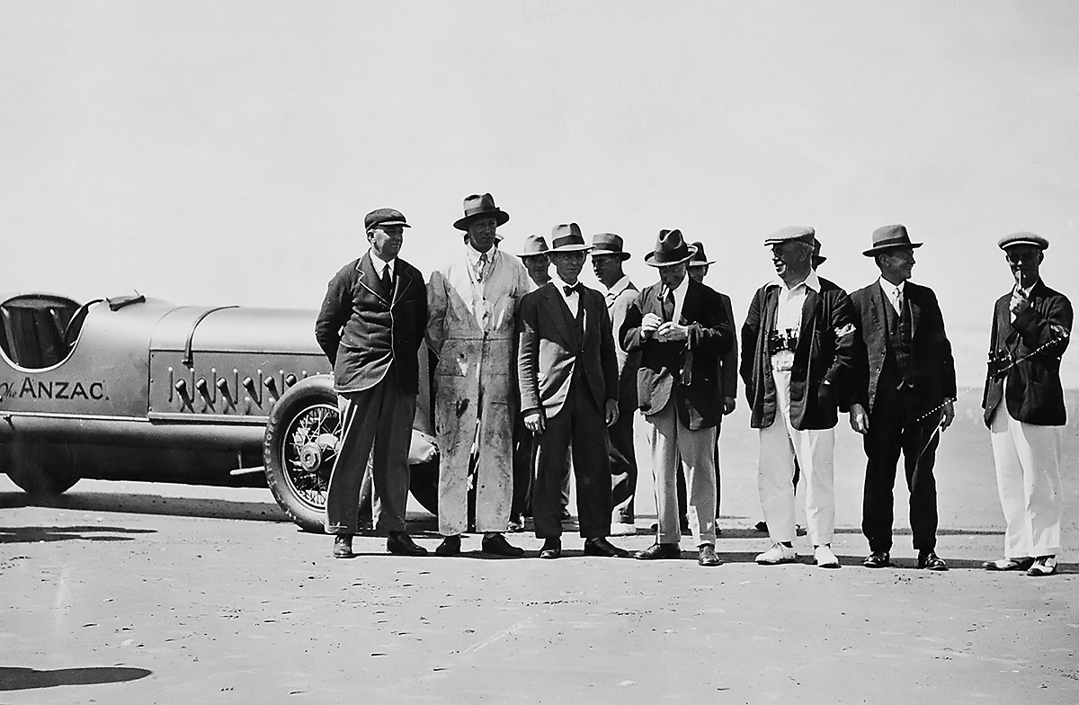
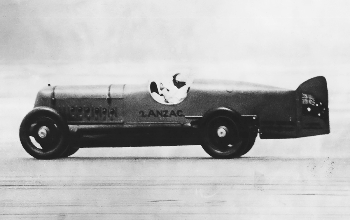
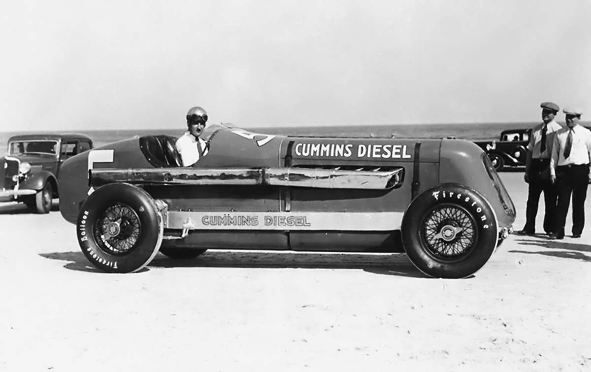
Clessie Cummins in Washington D.C. on tour after setting the diesel speed record at 100.755 mph (162.150 km/h) on 7 February 1931 in Daytona Beach, Florida. The car was slightly modified and entered in the 1931 Indianapolis 500 race. (Indiana Public Media image via flickr.com)

The Great Depression took its toll on Cummins and also affected auto racing. To increase race participation, Eddie Rickenbacker, then-owner of the Indianapolis Speedway and American Automobile Association Contest Board president, relaxed the racing rules to allow stock-block engines up to 366 cu in (6.0 L) in 1930. Cummins saw an opportunity to help fill the racing field and gain publicity in the Indianapolis 500 by fielding a diesel-powered racer in the 1931 race. Rickenbacker agreed to the plan and offered Cummins a provisional spot provided the racer could top 80 mph (129 km/h). However, the Cummins entry would not be entitled to any winnings, because of its guaranteed entry into the field.

Cummins contracted Augie Duesenberg to modify a Duesenberg Model A chassis and install a 4-cylinder Cummins Model U engine. The Model U was a marine engine with a 4.5 in (114 mm) bore, a 6.0 in (152 mm) stroke, and a displacement of 382 cu in (6.3 L). To make the engine conform to the displacement limit, the bore of the race engine was decreased by .125 in (3 mm), resulting in a bore of 4.375 in (111 mm). This resulted in a displacement of 361 cu in (5.9L). The engine had been modified with aluminum pistons and two intake valves but retained a single exhaust valve. The race engine produced 85 hp (63 kW) at 1,500 rpm and weighed about 1,600 lb (726 kg).

cummins 1931 8 indy

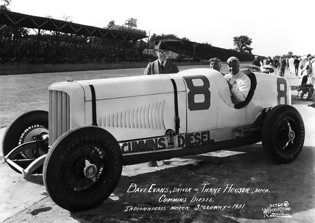
Clessie Cummins stands behind the Cummins Diesel Special #8 entered in the 1931 Indy 500. Dave Evans and Thane Houser are in the cockpit. Note the racer’s height. (IMS image)

To test the powertrain, Clessie drove the car to Daytona Beach, Florida and set a diesel flying-mile (1.6-km) speed record at 100.755 mph (162.150 km/h) on 7 February 1931. The racer was then driven to Washington D.C. and back to the Cummins factory, where it was modified in accordance with the Indy 500 rules. Its completed weight was a hefty 3,389 lb (1,537 kg).

For the Indy 500, the car was named the Cummins Diesel Special and given race #8. Dave Evans was the driver with Thane Houser as the riding mechanic / co-driver. The Cummins Diesel Special was regularly driven the 45 miles (72 km) from the Cummins factory in Columbus, Indiana to the Indianapolis Motor Speedway. The Cummins racer qualified at 96.871 mph (155.899 km/h), which was the 43rd fastest car. Since Rickenbacker had guaranteed a spot in the 40-car field, the Cummins Diesel Special was the slowest car in the 1931 Indianapolis 500. However, the Cummins team had a plan to pick up a few spots during the race.

cummins 1931 8 display

The restored #8 displayed in the Indianapolis Motors Speedway Museum. Note the engine’s four individual cylinders. (Doctorindy image via Wikimedia Commons)

On race day, 30 May 1931, the Cummins Diesel Special was driven from the factory to the raceway. The racer proved to be slow during the 500-mile (805-km) competition, but the fuel-efficient engine enabled the Cummins Diesel Special to run the entire race without stopping, the first and only racer to accomplish such a feat during the Indy 500. In those days, the race continued after the first-place car finished until each car that could finish had completed the 200 laps. The Cummins Diesel Special completed its 200th lap and finished the race 38 minutes after the race leader, which was enough to secure a 13th place finish. The diesel-powered racer averaged 86.170 mph (138.677 km/h) over the 500-mile (805-km) distance, and the amount of fuel used reportedly cost $1.40 ($23 in 2018 USD).

In 1932, Clessie Cummins and William G. Irwin (Cummins’ main financial backer) took the racer on a 5,000-mile (8,047-km) tour of Europe. This trip resulted in some modifications to the racer, such as the addition of a windshield and headlights. The Duesenberg-built Cummins Diesel Special was preserved by Cummins and restored to its Indy-race configuration. The car is often displayed in various museums and run on rare occasion at special events.

cummins 1934 6 indy

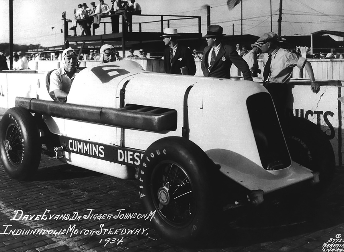
Dave Evans and Jigger Johnson in the four-stroke #6 at Indy in 1934. The Roots supercharger can just be seen at the front of the car. (IMS image)

The Cummins Team returned in 1934 to race in the Indy 500. Cummins fielded two Duesenberg-chassis cars for the race, each powered by an experimental, supercharged, aluminum, inline-four engine. The engine had a 4.875 in (124 mm) bore and stroke and displaced 364 cu in (6.0L). The difference between the cars was primarily a difference in engines, with one car using a four-stroke engine and the other car using a two-stroke engine. The Indy 500 race served as a test to compare the two different combustion cycle engines. The Roots-type supercharger was driven from the engine and installed at the front of the car. The supercharger in the four-stroke car took about 7 hp (5 kW) to run, compared with 37 hp (28 kW) for the two-stroke car, which also used the supercharger for cylinder scavenging. The four-stroke engine had one intake valve and one exhaust valve. The two-stroke engine had two exhaust valves and intake ports in the cylinder that were uncovered by the piston. Each engine produced approximately 135 hp (101 kW) at 2,500 rpm. The engines each weighed about 1,000 lb (454 kg), and each car weighed around 3,200 lb (1,451 kg).

cummins 1934 6 engine

The #6 car with the Roots supercharger passing induction air through the radiator and to the engine. (IMS image)

The four-stroke car, race #6, was driven by Dave Evans with John ‘Jigger’ Johnson as the riding mechanic. It qualified in 22nd place at 102.414 mph (164.819 km/h). During the race, #6 made its first pitstop after 200 miles (322 km). Unfortunately, engine torque damaged the transmission as the racer quickly accelerated to reenter the track. This forced Evans and Johnson to retire from the race, and #6 was awarded 19th place. The engine in #6 had operated flawlessly during the race. The car has been preserved by Cummins and is occasionally displayed for special events.

cummins 1934 6 display

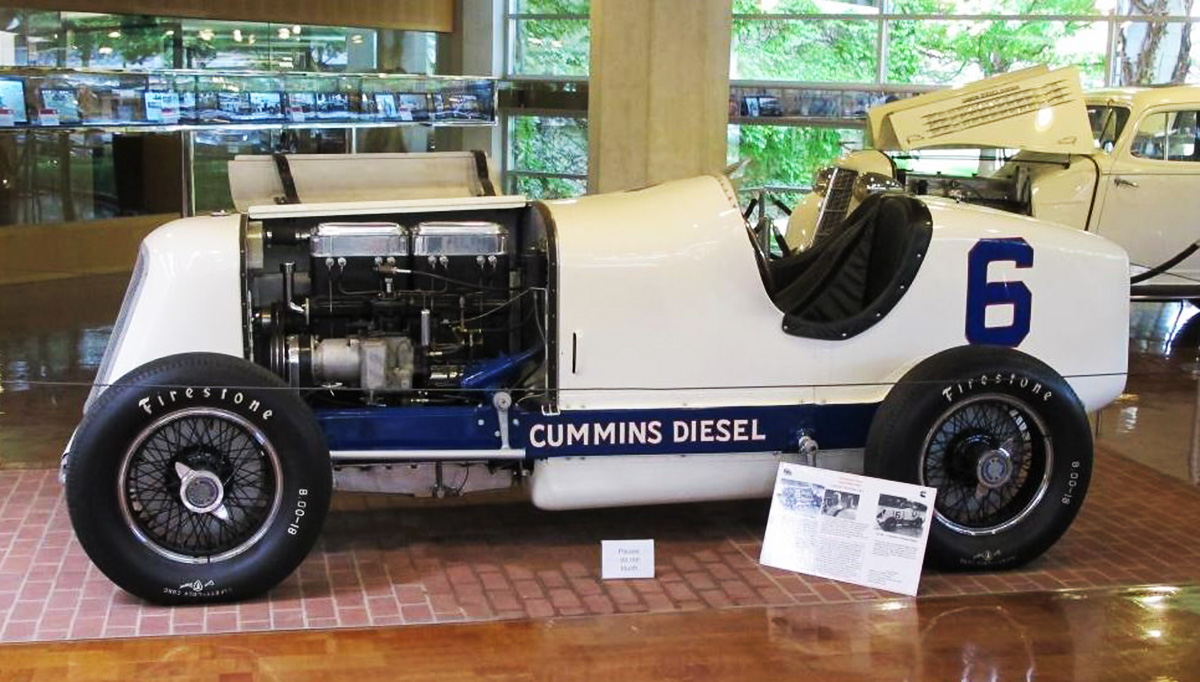
The restored #6 car displayed in the Cummins Museum at the Company’s corporate headquarters in Columbus, Indiana. (Ricky Berkey image)

cummins 1934 5 daytona clessie

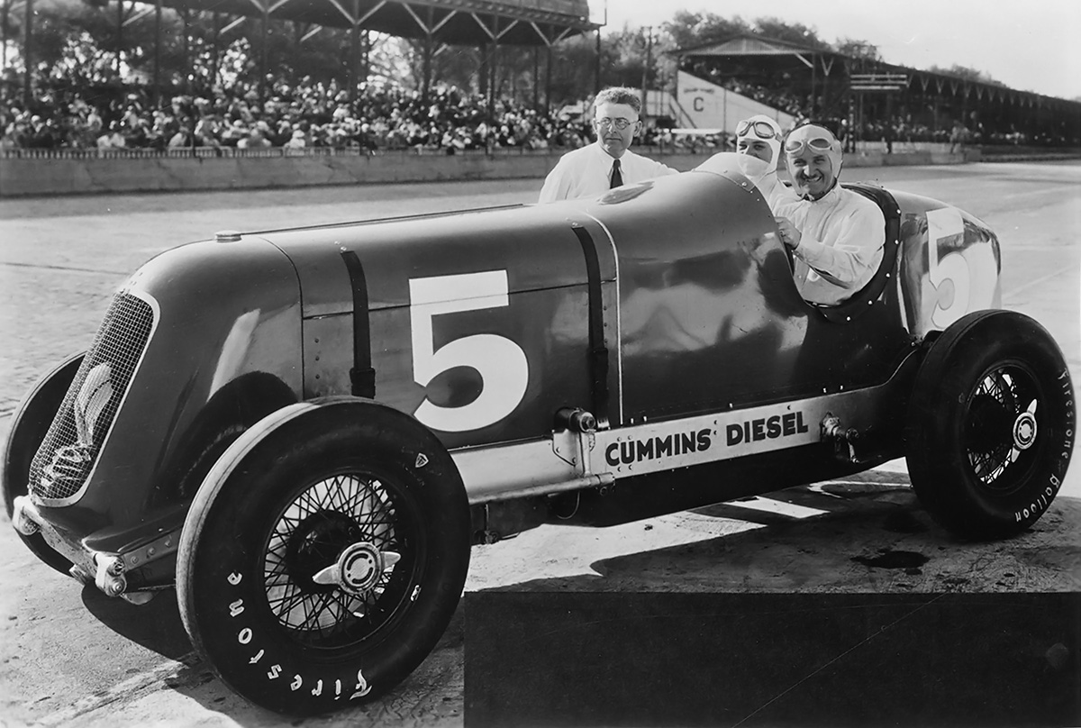
Clessie Cummins stands by the two-stroke #5 racer at Indy in 1934 with Stubby Stubblefield and Bert Lustig in the cockpit. The Roots supercharger can be seen through the car’s grille. The racer’s 12th place finish is the best for a diesel-powered car in the Indy 500. (Indiana Public Media image via flickr.com)

The two-stroke car, race #5, was driven by Stubby (Wilburn Hartwell) Stubblefield with Bert Lustig as the riding mechanic. The car qualified 29th at 105.921 mph (170.463 km/h). Although the two-stroke engine was temperamental, #5 went the distance and finished the 500-mile (805-km) race in 12th place, averaging 88.566 mph (142.533 km/h). Evans took over driving duties from Stubblefield around mid-race. Race #5 was the last car to complete the 200 laps—finishing the race trailing smoke and overheating. After the racer was shut down, the pistons seized in the cylinders. Some sources indicate that Clessie was so displeased with the two-stroke engine that it was tossed into a river as the team made its way back to Columbus. Because of the issues with the two-stroke engine, Cummins subsequently abandoned two-stroke development and focused on four-stroke engines.

cummins 1934 5 daytona

After Indy, a four-stroke, six-cylinder engine was installed in the #5 racer. Wild Bill Cummings set diesel speed records on Daytona Beach Florida in 1935 and is seen behind the wheel. The front of the car was stretched to accommodate the longer engine. Note the six-to-one exhaust manifold. (Cummins image)

Race #5 was later modified (lengthened) to accommodate a four-stroke, six-cylinder engine. Wild Bill Cummings used the updated #5 to set a flying-mile (1.6 km) diesel speed record of 133.023 mph (214.080 km/h) on 1 March 1935. The following day, Cummings increased the record speed to 137.195 mph (220.794 km/h). Cummings in Race #5 also set 5 km (3.1 mi) and 5 mi (8.0 km) records of 126.99 mph (204.37 km/h) and 112.07 mph (180.36 km/h) respectively. However, the event was not sanctioned, and none of these records were internationally recognized. Race #5 was preserved by Cummins in its record-setting form and is occasionally displayed in various museums.

Cummins 1934 5 Amelia Island

The restored #5 in its Daytona configuration with a four-stroke, six-cylinder engine. The car was displayed for a time at the Auburn-Cord-Duesenberg Museum on account of its Duesenberg chassis. As seen above, #5 is at the Amelia Island Concours d’Elegance in April 2019. (The Southern Concours / John E. Adams image)

It was not until 1950 that Cummins returned to the Indy 500. The car was called the Cummins Diesel Special (just like the 1931 entry) and wore race #61. Because of its green color, driver Jimmy Jackson referred to the car as the Green Hornet. The racer consisted of a modified Kurtis Kraft chassis powered by a supercharged inline-six engine based on the Cummins JBS-600 truck engine. The car used disc brakes, which was a first at Indy.

cummins 1950 61 indy

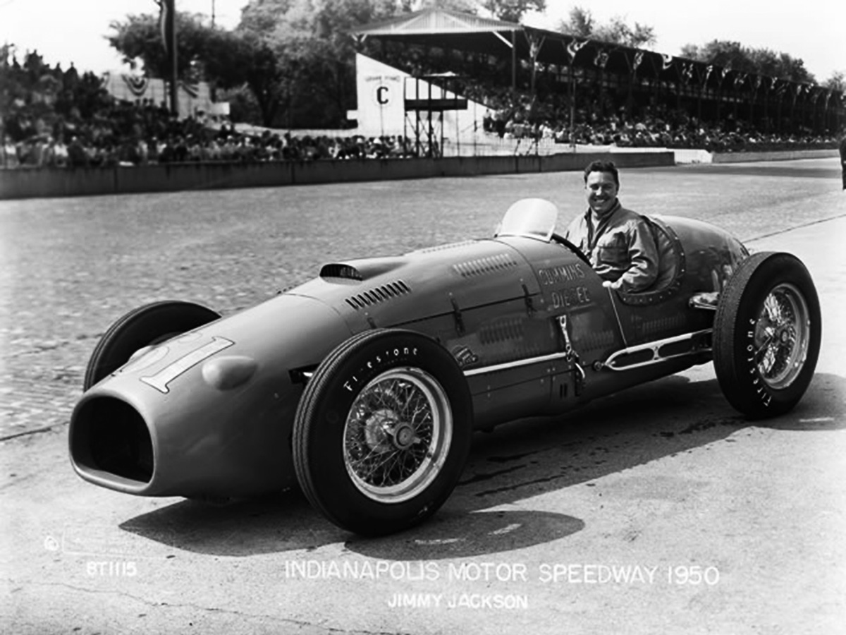
Jimmy Jackson sits in the 1950 Cummins Diesel Special #61 at Indy. Although much more refined compared to the earlier racers, #61 was still a heavy brute compared to the rest of the field. Induction air was brought in via the front tunnel. The scoop on the engine cowling provided clearance for the cylinder head and airflow to help cool the engine, but overheating was still a problem. (IMS image)

The Roots-type supercharger was crankshaft-driven and mounted in front of the engine. The special engine had four-valves per cylinder and used an aluminum crankcase, cylinder block, and head. Two injectors delivered fuel into each cylinder, and the engine used an early design of what would become Cummins’ PT (Pressure-Timed) fuel injection. The engine had a 4.125 in (105 mm) bore and a 5.0 in (127 mm) stroke. It displaced 401 cu in (6.6 L) and produced 320 hp (239 kW) at 4,000 rpm. With the ram-air effect of the racer at speed providing additional boost, the engine’s output increased to 340 hp (254 kW) at 4,000 rpm. The engine weighed 860 lb (390 kg).

cummins 1950 61 engine

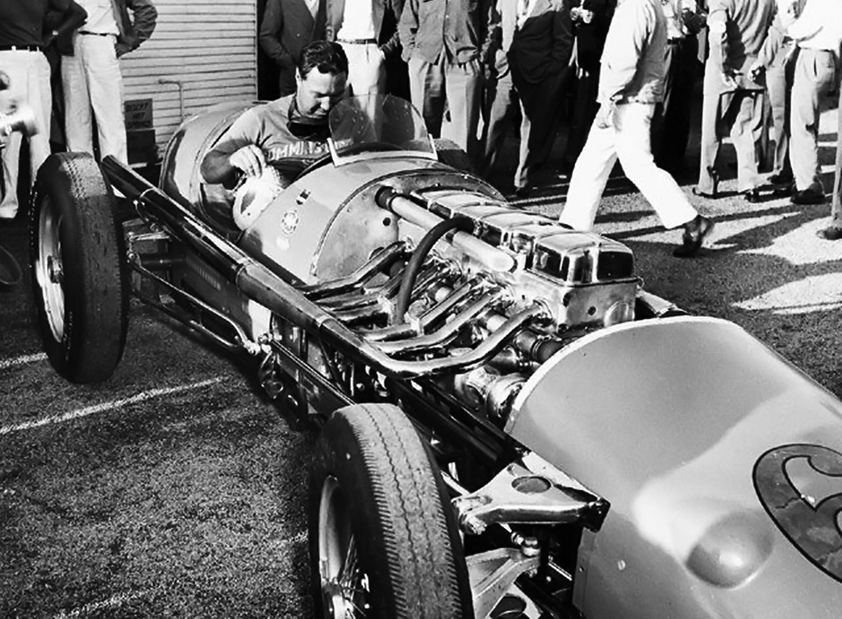
The uncowled #61 with Jackson in the cockpit. Note the crossflow head with the intake manifold on one side and the exhaust manifold on the other. The earlier Indy racers had the intake and exhaust manifolds on the same side (passenger) of the engine. The car’s independent front suspension was a first at Indy. (Motor Trend image)

Despite some difficulty, the diesel-powered Green Hornet eventually qualified for the Indy 500 at 129.208 mph (207.940 km/h), the slowest qualifying speed of the grid. During the race, the car was retired on lap 52, while in 29th place, because of issues with the engine’s vibration damper and supercharger drive. Repaired, and at the Bonneville Salt Flats on 11 September 1950, Jackson and the Green Hornet set six International diesel speed records: 163.82 mph (263.64 km/h) over 1 km (.6 mi), 165.23 mph (265.91 km/h) over 1 mile (1.6 km), 164.25 mph (264.33 km/h) over 5 km (3.1 mi), 161.92 mph (260.59 km/h) over 5 mi (8.0 km), 147.63 mph (237.59 km/h) over 10 km (6.2 mi), and 148.14 mph (238.41 km/h) over 10 mi (16 km). The previous diesel records up to 5 km (3.1 mi) were set by George Eyston and the Flying Spray in April 1936. The previous 5 km (3.1 mi) and 5 mi (8.0 km) records were those set by Wild Bill Cummings and Race #5 in March 1935. The Green Hornet was preserved by Cummins and is often displayed in various museums. On rare occasions, the car is run at special events.

cummins 1950 61 display

The 1950 racer was nicknamed Green Hornet on account of its paint. After Indy, #61 and Jackson set six diesel speed records at the Bonneville Salt Flats in Utah. The Green Hornet is pictured as displayed in the Indianapolis Motors Speedway Museum. (AutoDesign image)

In 1951, Cummins decided to make a serious attempt for the 1952 Indy 500. Clessie’s brother Don Cummins headed the team, with Nev Reiners as the chief engineer. Also on the team were Thane Houser (riding mechanic / co-driver for the 1931 Indy effort), Bill Doup, Mike Fellows, Art Eckleman, and Joe Miller. The Cummins Team worked directly with Frank Kurtis of Kurtis Kraft to design a low-slung chassis, and every opportunity was taken to exploit the chassis-engine combination.

cummins 1952 28 indy

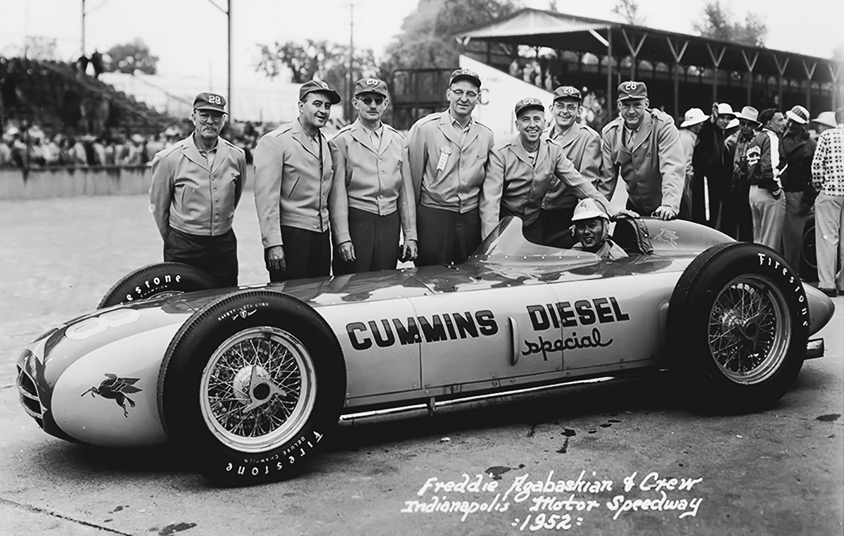
Freddie Agabashian and crew with the 1952 Cummins Diesel Special #28 at Indy. The engine installed on its side made the car a low and sleek racer. Compare #28’s height with that of the earlier racers. (IMS image)

Powering the new racer was a further development of the JBS-600-based engine used in the Green Hornet. Since the new engine was turbocharged, it is often referred to as a modified JT-600. The engine consisted of a magnesium crankcase with an aluminum cylinder bank and head. Concepts from Cummins’ NHH-series engines (inline-six laid on its side) were applied to the race engine, and it was installed in the racer’s chassis laid over at an 85-degree angle—nearly on its side. This resulted in a very low engine cowling about 23 in (.58 m) above the ground. The turbocharger was installed in front of the engine on the right side of the car and provided up to 20 psi (1.38 bar) of boost. Like with the Green Hornet, a precursor to the Cummins’ PT fuel injection system was employed. The engine had a 4.125 in (105 mm) bore, a 5.0 in (127 mm) stroke, and a displacement of 401 cu in (6.6 L). The power produced was 380 hp (283 kW) at 4,000 rpm and 430 hp (321 kW) at 4,500 rpm. The engine weighed around 750 lb (340 kg).

The crankshaft, transmission, and driveline were on the left side of the car, putting 150 lb (68 kg) of weight bias on the left side of the car for better handling around the oval track. The cockpit was offset to the right, and the driver’s position was very low, only 4 in (102 mm) off the ground. The racer’s configuration resulted in a very low center of gravity, but the car was quite heavy at around 3,100 lb (1,406 kg). The turbocharger was a first at Indy, as was the offset drivetrain and the car’s independent front suspension. The aerodynamics of the chassis and bodywork were fine-tuned in a wind tunnel, which was reportedly another Indy first.

cummins 1952 28 no body

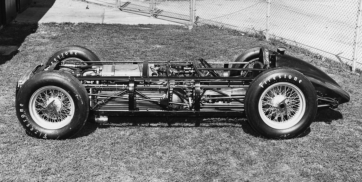
With the body removed, the compact nature of #28’s chassis is revealed. The turbocharger can just be seen between the front tires. On the left side of the car, note the underside of the crankcase and the driveline extending to the rear. (Cummins image)

The car was completed in late 1951, and testing began in November. Again christened as the Cummins Diesel Special, the car was given race #28 and was driven by Freddie Agabashian. Early testing indicated a very fast car, and Agabashian was careful not to reveal the racer’s full potential during practice sessions at Indy. Agabashian would not run full power for complete laps because there was some concern that the car would be banned had its true, competitive speed been reached. Fifteen minutes before the end of Pole Day qualifying, Agabashian took #28 out and set a one-lap record at 139.104 mph (223.866 km/h) and a
four-lap record at 138.010 mph (222.106 km/h). Agabashian and #28 had qualified in 1st place in a diesel. Agabashian had pushed the racer so hard that he tore the tread off some of the tires. The qualifying record was short-lived, as two cars later qualified with faster speeds, but it was still a major accomplishment for the Cummins Team.

On 30 May 1952, the Indy 500 was run. Agabashian in #28 found the diesel slower to accelerate than the other cars. Another problem cropped up with a buildup of tire rubber debris clogging the turbocharger intake. This issue ultimately caused the turbocharger to fail and forced #28 to retire on lap 71. At that point, Agabashian was in 5th place and had averaged 131.5 mph (211.6 km/h). The race was eventually won at a 130.843 mph (210.571 km/h) average, indicating #28 was keeping pace. Race #28 was credited with a 27th place finish. In short order, rules were changed, and the Cummins Diesel Special was the last diesel-engine racer to compete in the Indy 500.

cummins 1952 28 start

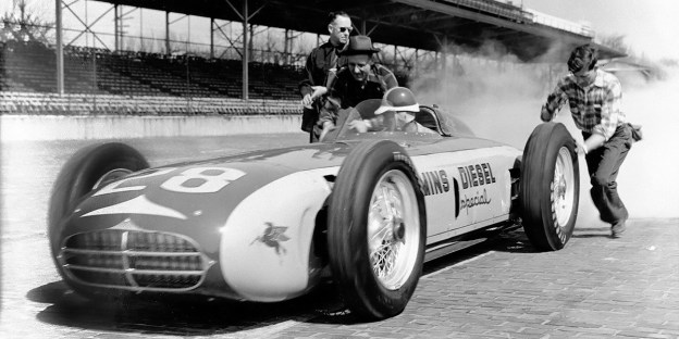
Agabashian and #28 set off from the pits at Indy for a practice run. Unlike racers of today, the smoke at the back of the car is diesel smoke exhaust and not tire smoke. Note the indentation ahead of the front tire. The body was so wide that body indentations were needed for full lock tire clearance. (Cummins image)

Race #28 was returned to the Cummins factory in Columbus, Indiana where it was preserved. A restoration in 1968 revealed that the crankshaft had cracked and would have failed completely had the turbocharger issues not brought a halt to #28’s race. The racer was occasionally run for special events until 1999. In 2016, the Cummins Diesel Special underwent a restoration and was run for the first time since 1999. The racer is often displayed at the Cummins Museum and run on rare occasion at special events.

In each of its four outings at Indy, Cummins took advantage of rules that enabled the displacement of diesels to be up to twice that of spark-ignition engines. While this did offer an advantage for diesels, nearly everything else about the engine was a disadvantage compared to the standard racers. Cummins used the Indy 500 to showcase its diesel engines, test new technology, and make a statement about diesel power.

cummins 1952 28 goodwood

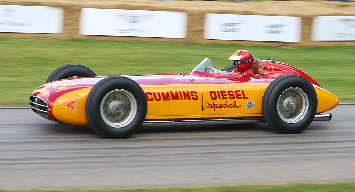
After its 2016 restoration, #28 participated in the 2017 Goodwood Festival of Speed in Chichester, UK. Bruce Watson, a retired Cummins Engineer, is driving the racer and also led the car’s restoration. (Steve Siler / Car and Driver image)

A sponsorship agreement between Cummins and the Indianapolis Motor Speedway will provide for all five diesel Indy cars to make a parade lap before the 2019 Indy 500. The event, which coincides with Cummins’ 100-year anniversary, will be the first time that the five cars have run together.

Cummins Diesel Indy Cars 2019

All five of the Cummins Diesel Indy Cars on display in May 2019 prior to the Indy 500 race. (Cummins image)

Sources:
– “Cummins at the Brickyard” by Karl Ludvigsen, Car Life (July 1969)
– “Diesels at Speed” by Griffith Borgeson, Motor Trend (December 1950)
– “The Triumph of the Diesel” Popular Mechanics (July 1934)
http://www.trucktrend.com/cool-trucks/0808dp-cummins-diesel-race-car/
http://www.trucktrend.com/news/1605-cummins-wakes-1952-diesel-special-indy-car-after-years-of-slumber/
http://triplettracehistory.blogspot.com/2016/01/the-1931-cummins-diesel-photo-by-author.html
https://www.allpar.com/corporate/bios/cummins.html
https://stevemckelvie.wordpress.com/2011/06/05/the-cummins-diesel-special-at-the-1952-indianapolis-500/
https://www.thetruthaboutcars.com/2015/10/clessie-cummins-made-diesels-king-road-almost-indy-part-one/
https://www.thetruthaboutcars.com/2015/10/clessie-cummins-made-diesels-king-road-almost-indy-part-two/
https://www.cummins.com/company/history/indianapolis-500
https://www.caranddriver.com/features/when-cummins-diesels-assaulted-indy-feature
https://www.conceptcarz.com/vehicle/z15198/duesenberg-cummins-diesel-indy-racer.aspx
https://www.hemmings.com/blog/index.php/2011/08/02/diesels-at-daytona/
https://cumminsengines.com/No-28-cummins-diesel-special-to-run-with-moto
https://www.hotrodhotline.com/feature/heroes/landspeedracing/2009/09newsletter122/

Smith Enterprise tow

Fred H. Stewart Enterprise (Smith-Harkness) LSR Car

By William Pearce

In 1930, Australian driver Norman Leslie “Wizard” Smith attempted to set a Land Speed Record (LSR) on Ninety Mile Beach (which is actually 55 miles / 88 km long) in New Zealand. His car, the Anzac, was built by well-known race driver, engineer, and fellow Australian, Donald James Harkness. Harkness was also the riding mechanic for the Anzac record runs. Smith and Harkness knew the 360 hp (268 kW) Anzac was not capable of setting an absolute speed record for the flying mile (1.6 km), but they hoped to set national records for Australia and New Zealand as well as a 10-mile (16-km) world record. Technically they were successful, but the 10-mile (16-km) record was not verified on account of a single run being made without a return run in the opposite direction. The Anzac was also used to gain experience that would be applied to the design and construction of a much more powerful car capable of 300 mph (483 km/h).

Smith Enterprise Harkness

Norman “Wizard” Smith and Don Harkness pose with the nearly completed Fred H. Stewart Enterprise in 1931. Note how the body sloped up in front of the cockpit. This was done in an attempt to increase downforce at the center of the car to aid stability at high speeds.

Setting world speed records is an expensive endeavor. While Smith and a few friends funded most of the Anzac, the much larger and faster LSR car would need financial resources beyond that which Smith and his partners could provide. Fortunately, Smith was able to leverage his success with the Anzac and as a racer to gain the financial backing of Australian businessman and politician Frederick Harold Stewart. The one stipulation set by Stewart was that the new LSR car be named the Fred H. Stewart Enterprise. The car was originally to be named Anzac II, but at the time, Australian policy stated that ANZAC can only refer to the Australian and New Zealand Army Corps and cannot be used in any other fashion without prior permission. As a result, Smith had to take the name off his previous racer and select a different name for the new racer. The financing terms were agreed upon, and Smith and Harkness focused on building the LSR car, the Fred H. Stewart Enterprise (Enterprise).

To power the Enterprise, Smith and Harkness needed an engine much more powerful than anything they could obtain themselves. They sought a 1,600 hp (1,193 kW) Rolls-Royce R engine developed for the 1929 Schneider Trophy contest. The Enterprise team turned to the Australian government for assistance, and the Australian Prime Minister, James Scullin, reached out to the British government. Ultimately, the British Air Ministry loaned Smith the latest Napier Lion VIID W-12 engine, capable of 1,450 hp (1,081 kW) at 3,600 rpm. This was the same type of engine that Malcolm Campbell would soon install in his latest Blue Bird revision, the Campbell-Napier-Railton Blue Bird. At the time, the engine’s particulars were considered secret, and the Air Ministry stipulated that only Smith, Harkness, and two Enterprise crew members be allowed to work on it. Some reports indicate that a deposit of £5,000 was required, which was paid by Stewart, and that a Rolls-Royce engine was expected right up until the crate was opened to reveal the Napier. The taller and less-powerful Lion necessitated a slight redesign of the Enterprise, and the car’s estimated top speed decreased to 280 mph (451 km/h).

Smith Enterprise build

The Enterprise under construction at Harkness & Hillier Engineering Works. Smith is sitting, with Harkness at his right. In front of the Napier Lion engine is Smith’s wife, Harriet. Note the screw jacks at the rear of the car, the leaf-spring rear suspension, and the size of the frame rails.

The Fred H. Stewart Enterprise was designed by Harkness and built at the Harkness & Hillier Engineering Works in Five Dock, near Sydney. The car resembled the 930 hp (694 kW) Irving-Napier Golden Arrow, which Henry Segrave had used to set the then-current LSR at 231.362 mph (372.341 km/h) on 11 March 1929. Like the Golden Arrow, the Enterprise had a chisel-shaped front end leading to a tightly-cowled Lion engine. Its wheels were set outside of the bodywork, and the cockpit was positioned toward the rear and flanked by driveshafts connected to the rear axle. One major difference in appearance was that the Enterprise had two stabilizing tails, each extending back behind the rear wheels. With an additional 520 hp (388 kW) and 17-percent less frontal area, Smith and Harkness thought the Enterprise would go faster than the Golden Arrow.

The Enterprise’s chassis consisted of two large frame rails connected by various cross members. Each corner of the frame had provisions for a screw jack to easily raise the car. The Lion engine was nestled between the frame rails and connected to a three-speed transmission. Output from the transmission was split into two drive shafts that passed through armor-plated housings on both sides of the driver’s seat. Each drive shaft connected to a drive box that was connected to a rear wheel. The front wheels appear to have had very minimal suspension, and the rear wheels were supported by leaf springs positioned above the frame. The frame, powertrain, and suspension were all designed to minimize the Enterprise’s height.

Smith Enterprise debut

At its christening on 26 October 1931, the Enterprise was fitted with relatively small aerodynamic fairings behind the rear wheels. It is not clear if this was Harkness’ final vision for the car, as other photos show no front fairings at all.

Separate drag links extended from the steering box positioned in front of the cockpit to the front wheels. A tie rod connected the front wheels together. The steering system enabled 20 degrees of wheel movement. A close-fitting body covered the Enterprise. The body was designed to push the middle of the car down at high speeds. A hump on each side of the cockpit enclosed the suspension for the rear wheels. The humps tapered down to form a wedge at the rear of the car. The body surrounding the cockpit tapered back to a point. The stabilizing tail fins, built from steel tube frames and covered with fabric, extended behind the rear wheels. A flat-plate windscreen was mounted at an angle just before the cockpit, and the fuel tank was positioned behind the cockpit.

The Enterprise was 26 ft (7.92 m) long, 69 in (1.75 m) wide, 36 in (.91 m) tall in front of the cockpit, 42 in (1.07 m) tall at the top of the cockpit, and 48 in (1.22 m) tall at the tail fins. The car had 7.5 in (191 mm) of ground clearance and weighed around 6,700 lb (3,039 kg). Only the rear wheels had provisions for brakes. Smith purchased a set of special Dunlap slicks guaranteed to 310 mph (500 km/h) for the speed runs. These tires were 37 in (940 mm) tall and 7 in (178 mm) wide. Like Smith’s Anzac, the Enterprise was finished in a golden color and had Australian flags painted on its tails. While the Enterprise was being built, Campbell set a new flying-mile (1.6-km) LSR at 245.736 mph (395.474 km/h) on 5 February 1931.

Smith Enterprise tow

The Enterprise without any front wheel fairings and with Smith in the cockpit. As designed, the Enterprise was a rather sleek machine. Note the brake link extending from the cockpit back to the rear wheel and the lack of brakes on the front wheels.

The Enterprise was anticipated to be completed around February 1931. However, delays with the car’s construction along with separate business matters preoccupying Smith, Harkness, and everyone else involved with the car, resulted in the Enterprise not being completed until the end of 1931. During this time, the Auckland Automobile Association built a garage at Hukatere, near the mid-point of Ninety Mile Beach. The garage was constructed for Smith and for others who might pursue future record attempts, as Malcolm Campbell was considering using Ninety Mile Beach. A side effect of the new garage was that Smith would no longer use Star Garage in Kaitaia, and some locals saw this as a slight against the town. This issue, combined with the lengthy delays, made many on the northern tip of the North Island have a general disdain for Smith and his record runs.

The incomplete Enterprise made a few public appearances in April and August 1931. Part of the delay in finishing the car was caused by a disagreement between Harkness and Smith on how to cool the Napier Lion. Harkness had designed the Enterprise to use ethylene glycol chemically cooled in a heat exchanger by methyl chloride (Chloromethane or Refrigerant-40). This method would leave the car aerodynamically clean without incorporating any radiators. Because of the relatively untried nature of chemical cooling and its high cost, Smith wanted to employ conventional water cooling with a radiator housed in a streamlined fairing at the front of the car, which was the method used on the Campbell-Napier-Railton Blue Bird. It should also be considered that Napier may have demanded that water-cooling be used on the loaned engine. Frustrated and running out of time, Harkness designed and constructed a pair of conventional radiators that mounted just before the front tires. Fairings mounted behind the front tires would serve as water reservoirs for the cooling system. With the exception of bracing for the radiators, this left the front of the car aerodynamically clean, and the radiators probably did not create any more drag that the tires just behind them. However, the system looked cobbled-together and very unrefined. Smith felt Harkness’ design was totally inadequate.

Smith Enterprise radiator

The Enterprise most likely seen arriving in Hukatere. The truck in the background transported the car from Awanui to Hukatere. The large radiator at the front of the car has been shrouded in a canvas cover. The new reservoir fairings are attached behind the front wheels, but the tail fins are not installed.

When the Enterprise was christened on 26 October 1931, it still had no visible means of cooling the engine, and small fairings behind the front wheels were installed for aerodynamic purposes only. The strain of everything had become too much, and Harkness suffered a nervous breakdown at the beginning of November. The Enterprise was started for the first time on 18 November, and preparations were made to ship the car to New Zealand.

At the request of Smith, and without the knowledge of Harkness, Lawrence James Wackett, perhaps Australia’s foremost authority on aviation and aerodynamics at the time, had analyzed the Enterprise’s cooling system and submitted a report to Smith a few days before the trip to New Zealand. Wackett had noted that the radiators did not have sufficient capacity to cool the Lion engine and that their installation would likely fail at high speed. When the Enterprise arrived in Auckland, New Zealand on 8 December, the disagreement on engine cooling had yet to be resolved. The radiators were not installed, but they had been shipped with the car to be added once the Enterprise arrived in New Zealand.

Around 10 December 1931, the Enterprise was fully assembled with its twin radiators and underwent a safety inspection, which it failed. The mounting of the radiators was deemed insufficient and was predicted to collapse at high speeds. Harkness persisted with the twin radiator design, and the tremendous strain that Harkness was under really began to show—political maneuvering brought an end to his company’s main source of income; his other business ventures were failing, and he was experiencing issues in his personal relationships. With the failed safety inspection in hand, Smith made his move and served Harkness with a restraining order, ousting him from further involvement with the Enterprise. Smith was not happy about the situation, but he felt that his priority needed to be fixing the Enterprise so that he could proceed with record attempts. Harkness stayed in Auckland while the rest of the party moved north, and he left New Zealand around 8 January 1932.

Smith Enterprise AAA garage

The Enterprise being towed out of the newly-constructed garage at Hukatere. The large, odd radiator truly spoiled the car’s looks and aerodynamics. Note the Dunlop road tires.

Before leaving Australia, Smith had made arrangements to design, build, and mount a new radiator to the Enterprise. Since Smith now had control of the car and knew the twin radiator design was flawed, he moved the Enterprise to an Auckland garage to fabricate a conventional radiator. The radiator work was conducted somewhat secretly, and the changes to the Enterprise surprised many when the car arrived in Awanui by skiff on 3 January 1932. The massive rectangular radiator absolutely ruined the lines of the Enterprise, but the radiator was an emergency fix done with little time. Smith defended the cooling system, comparing it to the type then used by Campbell on the latest Blue Bird. While the configuration was similar, the implementation on the Enterprise was not as refined as the radiator installation on the Campbell-Napier-Railton Blue Bird. The large, flat-faced, three-core radiator was covered in a fairing that stretched from the front of the car back to the engine cowling. In addition, the large wheel fairings constructed as water reservoirs had been installed behind the front wheels in place of the original, smaller fairings. The radiator added around 300 lb (136 kg) of weight and almost 2 ft (.61 m) of length, making the Enterprise approximately 7,000 lb (3,175 kg) and 27 ft 11 in (8.51 m) long.

Bad weather and poor conditions kept the Enterprise in its garage at Hukatere and off Ninety Mile Beach until 11 January 1932, when Smith made his first practice run. A speed of 125 mph (201 km/h) was achieved, and this was basically the first time the Enterprise was driven at any speed. Smith was satisfied with the shakedown run and prepared for an attempt on the 10-mile (16-km) record. The bad weather and poor conditions persisted, and it was not until 26 January that Smith felt the still-mediocre conditions were acceptable enough for an attempt. As the Enterprise ripped southeast on the beach, the wet sand literally sandblasted Smith and the car. At a speed around 228 mph (367 km/h), the car went out of control as it hit a patch of wet sand. Smith had to slow to 90 mph (145 km/h) before recovering, and then he pressed on to finish the run in 3:59.945 with an average speed of 150.034 mph (241 km/h). The toheroa shells on the beach had ripped up the special Dunlop slick tires during the run, and Smith decided to install the treaded road tires for the return run. The road tires were 36 in (914 mm) tall and 6 in (152 mm) wide. Because of the tires and conditions, Smith kept the Enterprise at a more sedate and even pace on the northwest run, completing the distance in 3:22.097 with an average of 178.132 mph (286 km/h). The average speed over both 10-mile (16-km) runs was 164.084 mph (264.077 km/h), breaking the previous record of 137.206 mph (220.811 km/h) set by Gwenda Stewart on 13 February 1930. Of course, Smith had hoped for and anticipated much more.

Smith Enterprise slicks

Smith sits in the cockpit before making a 10-mile (16-km) record attempt on Ninety Mile Beach. The Enterprise is equipped with the Dunlop slicks. Note the fuel filler cap behind the cockpit and the fabric covering of the tail fins distorted by the steel frame.

Smith was battered and bruised from the run; wet sand covered everything, including his goggles and the Enterprise’s windscreen. Better conditions were an absolute necessity before further attempts could be made and higher speeds attained. Curiously, various news outlets reported that Smith and the Enterprise made an LSR attempt on 27 January 1932, with 224.945 mph (362.014 km/h) on the first run and 199.285 mph (320.718 km/h) on the second. The speeds averaged to 211.115 mph (339.757 km/h), more than 34 mph (55 km) short of Campbell’s record. However, Smith, Harkness, and New Zealand and Australian newspapers deny that such an attempt was ever made. Where the erroneous report originated is not known.

After the run on 26 January 1932, Smith and the Enterprise took some time off. A new, smaller radiator was fitted because the previous radiator had worked a bit too well. The new radiator was only about 10% smaller and did not improve the Enterprise’s looks. Smith took the Enterprise out for a test run on 24 February and confirmed the new radiator was working well. That same day and half a world away, Campbell increased the 5-km (3.1-mi) record to 241.569 mph (388.768 km/h), the flying mile (1.6 km) record to 253.968 mph (408.722 km/h), and the flying kilometer (.6 mi) record to 251.340 mph (404.493 km/h).

Smith Enterprise Beach

The Enterprise running along Ninety Mile Beach with Dunlop road tires. With its radiator slightly out of frame, the car does not appear too odd.

Smith and the Enterprise made ready for future attempts at the 5-mile (8-km) and absolute speed records on 25 February 1932, but the weather did not cooperate, and tensions were brought to an all-time high. A disagreement at the hotel resulted in Smith and his party checking out and returning to Auckland; the Enterprise stayed in the garage at Hukatere. The party returned to a different hotel around 19 March, hoping for improved conditions and a smooth beach. However, some of the worst weather in 30 years continued to prevent any record attempts. More bad luck came in early April with legal proceedings filed against Smith by Harkness. Harkness, who was in Sydney, was absolutely furious when he saw the radiator modifications applied to the Enterprise. In addition, Smith’s constantly-delayed attempts on the record caused many to question his abilities, but most of these individuals were far from Ninety Mile Beach and did not have a grasp on its unsuitable condition.

In the meantime, on 26 February 1932, Campbell at Daytona Beach set new records for 5 km (3.1 km), 5 miles (8 km), and 10 km (6.2 mi). The respective speeds achieved in the Blue Bird were 247.941 mph (399.023 km/h),  242.751 mph (390.670 km/h), and 238.669 mph (384.101 km/h).

On 5 April 1932, Smith took the Enterprise on a brief drive along the unsuitable beach. The following day, Smith packed up the Enterprise and started the journey back to Auckland. While in Auckland, a new windscreen that revolved to clean itself of sand was installed. By the end of April, Smith and the Enterprise had returned to Hukatere, where the wait continued as rough weather made the conditions unacceptable for a record run. Because so many delays had occurred with the car’s arrival in New Zealand and with the record runs, detractors coined a new nickname: “Windy” Smith, implying he talked a lot about his plans but failed to come through. Locals had long since grown tired of the spectacle and inconvenience Smith’s record runs had caused.

Smith Enterprise wet run

This photo of Smith in the Enterprise, on what is most likely one of the 10-mile (16-km) runs, gives a good impression of the wet and less-than-ideal conditions on Ninety Mile Beach. The heavy rain created a couple of shallow streams that ran across the course, making it very unsuitable for a car traveling at high-speeds.

After all of the waiting and associated drama, Smith was ready to make another run in the Enterprise on 1 May 1932. Ninety Mile Beach was wet and still not in a good condition, but something had to be done, and Smith targeted the 5-mile (8-km) record. As the Enterprise traveled northwest on Ninety Mile Beach and accelerated through 170 mph (274 km/h) toward the start of the course, the Napier engine began backfiring and caught fire. Saltwater spray had inundated the engine compartment and caused arcing from the magnetos. The sparks ignited fuel around the Lion’s carburetors. Smith slowed as fast as he could and jumped from the car as it was still moving. The fire was quickly brought under control, and the Enterprise was returned to the garage at Hukatere. The damage was judged as not too severe, but Smith had spent a rough five months in New Zealand and was not interested in staying any longer.

Smith vowed to return the next year to go after the record, but he never did. Smith, his entourage, and the Enterprise returned to Sydney, and the car was tucked away in the garage of Smith’s friend Ted Poole. The cost of the record attempts began to set in as Harkness and others accused Smith of being either afraid to make a record attempt or incapable of driving at the speeds needed. Neither of the accusations were true. The truth was that pursuit of the LSR had cost Smith much of his savings, some of his dignity, and a few of his friendships. Eventually, Smith prevailed in a slander suit he brought against an Australian newspaper, but the rift with Harkness was never closed. In mid-1933, Smith talked about racing the Enterprise on Lake George, but plans for the site never came to fruition. Smith’s 10-mile (16-km) record stood until 6 September 1935, when George Eyston in Speed of the Wind achieved an average of 167.09 mph (268.91 km/h), 3 mph (5 km) faster than Smith, at the Bonneville Salt Flats in Utah. Later in life, Smith was happy to talk about his racing exploits, with the exception of the LSR attempts. Smith stored the Enterprise for a time, but the car was ultimately disassembled, and the Lion engine was sold for use in a speedboat. The Enterprise’s frame sat outside of Smith’s shop until at least 1958, the year Smith passed away, but no part of the car is known to exist.

Smith Enterprise engine fire

The damage to the Enterprise after the Napier Lion caught fire during the 5-mile (8-km) attempt was fairly isolated. The coolant line to the radiator extended from the center of the cowling. The return lines ran outside of each frame rail.

This article is part of an ongoing series detailing Absolute Land Speed Record Cars.

Sources:
Wizard of Oz by Clinton Walker (2012)
The Real Wizard Smith by Steve Simpson (1977)
The Land Speed Record 1930-1939 by R. M. Clarke (2000)
– “Australian Fails To Beat Campbell’s Auto Speed Record” The Syracuse Herald (27 January 1932)
– “Radiators On Racing Cars” The Sydney Morning Herald (2 February1932)
– “Did “Wizard” Smith Attempt Record?” Truth (3 April 1932)
http://www.gregwapling.com/hotrod/land-speed-racing-australia/land-speed-racing-australia-enterprise.html
http://www.gregwapling.com/hotrod/land-speed-racing-australia/land-speed-racing-australia-norman-smith.html
http://www.gregwapling.com/hotrod/land-speed-racing-australia/land-speed-racing-australia-don-harkness.html
http://adb.anu.edu.au/biography/smith-norman-leslie-8481

Smith Harkness Anzac test

Smith-Harkness Anzac LSR Car

By William Pearce

Norman Leslie Smith was an Australian professional racing driver. In the 1920s, he began to dominate hill climb, endurance, and point-to-point speed events. The nickname “Wizard” was bestowed upon him in December 1922 after his uncanny abilities behind the wheel were demonstrated while he won a 1,000-mile (1,609-km) Alpine rally in Melbourne. Earle Croysdill was Smith’s riding mechanic, and more than 50 racers had entered the event. Smith drove his racer from his home in Sydney, completed the race, and then drove the 560 miles (900 km) back to Sydney.

Smith Harkness Anzac nearly complete

The nearly-finished Anzac LSR car sits outside of the Harkness & Hillier Engineering Works in Five Dock. The car is missing its windscreen, seats, and gold paint. An additional louver was added under each exhaust stack, and the Australian flag painted on the tail would later be moved higher with “Advance Australia” written under it. Don Harkness is on the extreme right; he is looking at Norman “Wizard” Smith, who is holding one of the two black shop cats that, for a time, made the Anzac their home.

During 13 and 14 March 1928, Smith captured the Australian records for distances covered in 6, 12, and 24 hours while driving a Studebaker Commander that was stock, with the exception of an additional fuel tank. The respective distances and speeds traveled for the records were 455 miles at 75.8 mph (732 km at 122.0 km/h), 857 miles at 71.4 mph (1,379 km at 114.9 km/h), and 1,701 miles at 70.9 mph (2,737 km at 114.1 km/h). Not quite done, Smith, with Ted Poole and Len Emerson, drove from the western coastal town of Fremantle (near Perth) to the eastern coastal town of Brisbane by way of Adelaide, Melbourne, and Sydney. Their 6-day, 5-hour, and 22-minute journey spanned from 31 March to 6 April and covered some 3,700 miles (5,955 km), including backtracking. The trip set new point-to-point records between all of the major Australian cities they visited.

In late 1928, Smith happened upon Jack Mostyn, former Mayor of Sydney, who was fixing a flat tire. It was during this impromptu roadside meeting that the idea of creating an Australian Land Speed Record (LSR) car was born. At the time, the speed record stood at 207.552 mph, set by Ray Keech in the White Triplex Special on 22 April 1928. Smith and Mostyn did not intend to go directly after this record. First, they would build a car that could achieve around 175 mph. This car would be capable of setting Australian speed records and records over longer distances. If everything went well, a second LSR car would be built with a top speed of 250 mph in mind. But to achieve such lofty goals, the men needed an engineer to design and construct the cars.

Smith Harkness Anzac test

Finished, the Anzac is taken on a test run by Smith and Harkness. The name “the Anzac” was not painted on the car until later. It is not clear when the name was assigned to the car. Note that both front tires are essentially off the ground.

Smith and Mostyn turned to Donald James Harkness, a well-known race driver and engineer. Being around the same age, from the same area, and competing in the same events, Smith and Harkness had known each other for some time. Harkness agreed to partner with Smith and Mostyn to design and build the LSR cars for just the cost of their parts. The first car was the Anzac, named as a tribute to the Australian and New Zealand Army Corps, which had fought in World War I. Smith had joined to fight in World War I, but rheumatic fever ended his service and returned him to Australia.

The Anzac was designed by Harkness and built at the Harkness & Hillier Engineering Works in Five Dock, near Sydney. The car was of a conventional layout and about 20 ft (6.1 m) long with an 11 ft (3.4 m) wheel base and a 4 ft 8 in (1.4 m) track. The Anzac was built on a heavily modified and strengthened Cadillac frame and powered by a 360 hp (268 kW) Rolls-Royce Eagle IX V-12 engine. The Eagle IX was the latest and last of the Eagle line, the first of which was designed in 1915. Purchased as surplus from the Royal Australian Air Force, it was the most powerful engine Smith and Harkness could acquire.

The three-speed transmission, originally from the Cadillac, and drivetrain of the Anzac had been configured for an engine with a clockwise rotating crankshaft. As installed in the Anzac, the engine’s crankshaft rotated counterclockwise. A special transfer case was built and installed to take the counterclockwise input from the engine and convert it to a clockwise output for the drivetrain. The transfer case added weight and complexity and consumed some engine power. However, the transfer case had a 2:1 overdrive gearing. Modifications to the engine enabled 2,800–3,000 rpm, which gave the Anzac a theoretical top speed of 175–188 mph (282–303 km/h).

Smith Harkness Anzac Mobil

Smith looks on as Harkness pours oil into the Anzac’s tank during this publicity shot. Note the Vacuum Oil Company’s Mobiloil BB (SAE 50) oil can with the gargoyle logo. The Vacuum Oil Company was one of the few sponsors of the Anzac. When Vacuum merged with the Standard Oil Company of New York (Socony) in 1931, the “Mobil” name was retained for the oil, but Socony’s red Pegasus was used as the logo.

Efforts were made to keep the Anzac relatively clean aerodynamically, but it was not very streamlined. The Eagle’s individual exhaust stacks protruded from the engine’s cowling, and a radiator cap with a temperature gauge sat proud at the front of the car. A large triangular opening at the front of the car brought in air to the radiator, and the air exited from louvers cut into the sides of the engine cowling. The cockpit accommodated a driver and a riding mechanic. A small windscreen protected the driver, but the riding mechanic was exposed to the slipstream. The fuel tank was positioned behind the cockpit, and an oil tank was located behind the rear axle. The car’s body tapered behind the cockpit, and a stabilizing tail was attached to its extreme rear. The Anzac was funded primarily by Smith, with few sponsors. When it was finished, the car was painted gold with an Australian flag on its tail.

When the Anzac was completed at the end of 1929, the LSR stood at 231.362 mph (372.341 km/h), set by Henry Segrave in the 930 hp (694 kW) Irving-Napier Golden Arrow on 11 March 1929. A number of other record contenders were preparing cars, including Kaye Don in the “4,000 hp” Sunbeam Silver Bullet and Malcolm Campbell, who was reworking his Blue Bird from 900 hp (671 kW) to 1,450 hp (1,081 kW)—both Don and Campbell were eyeing 250 mph (402 km/h). Smith and Harkness knew the 360 hp (268 kW) Anzac was at best capable of 175 mph (282 km/h) and would not be able to compete with the LSR monsters. The absolute LSR was far out of reach, but the Anzac was capable of setting local speed records and of setting records over longer distances. The Anzac also served to gain LSR experience that would be applied to the construction of a faster car.

Smith Harkness Anzac beach group

Smith and Harkness, both on the far left, pose with others and the Anzac on Ninety Mile Beach. Note the louvers added under the exhaust stacks. The Firestone Tire and Rubber Company provided the tires for the record runs.

Smith had spent some time searching for a suitable location to run the Anzac and had found Ninety Mile Beach, which is actually 55 miles (88 km) long. Ninety Mile Beach is situated just north of Kaitaia, at the north end of New Zealand. Apparently, Smith did not investigate Lake Eyre or Lake Gairdner, both in Australia and both the future sites of many speed runs. Before shipping the car off to New Zealand, test runs were conducted on Seven Mile Beach near Gerringong, about 80 miles (130 km) south of Sydney. The Eagle engine was started and warmed up using a set of “soft” spark plugs, which ran hotter to burn off deposits but were prone to heat damage. Once at temperature, the engine was shut down, and the 24 “soft” plugs were replaced with “hard” plugs, which ran cooler and better withstood the high temperatures inside the engine at power. On 1 December 1929, Smith, Harkness (as a riding mechanic), and the Anzac set a new Australian absolute speed record at 128.571 mph (206.915 km/h). The previous record stood at 107.14 mph (172.43 km/h) and was set by Harkness on 17 October 1925.

Smith and the Anzac had arrived in Auckland, New Zealand by 31 December 1929 and made their way to Kaitaia. On his previous visit, Smith had arranged with Fred Mitchell, owner of Star Garage in Kaitaia, to use the garage as his base of operations. In addition, the garage’s chief mechanic, Charlie Bowman, would assist Smith with maintaining the Anzac. With the car ready and the weather acceptable, Smith drove the Anzac around on public roads for a little extra publicity before the record attempts. While the large and loud Anzac certainly turned heads, this escapade also damaged the clutch. Repairs were subsequently completed at Star Garage, but the job was made much more difficult because of the added transfer case. Rather than fix the clutch and risk it failing again, the transmission was coupled directly to the transfer case. From then on, the Anzac was started and stopped in gear, and Smith shifted without the aid of a clutch.

Smith Harkness Anzac beach run

The Anzac in its final form makes a test run on Ninety Mile Beach in New Zealand. The filler cap for the fuel tank can be seen on the rear of the car.

A storm had made Ninety Mile Beach temporarily unsuitable for any record attempts, but the tides quickly repaired the damage and returned the beach to a near-perfect condition. However, sharp toheroa shells littered the beach and cut into tires. On 11 January 1930, Smith and Harkness pushed the Anzac and established a New Zealand flying mile (1.6 km) speed record. The southeast run was completed in 24.6 seconds for an average speed of 146.341 mph (235.513 km/h)—this speed is often mistakenly reported for the event. Rain slowed the northwest run, which was completed in 25.4 seconds at an average of 141.732 mph (228.096 km/h). The average of the two runs was 144.037 mph (231.805 km/h). Six days later on 17 January 1930, Smith and Harkness made an attempt on the 10-mile (16-km) World LSR, then held by Leon Duray* at 135.333 mph (217.798 km/h). The Anzac averaged 148.637 mph (239.208 km/h) on the southeast run, which took 242.2 seconds. Smith was told that because of the distance, no return run would be necessary and that a new 10-mile (16-km) world speed record had been established, breaking the existing record by over 13 mph (21 km/h).

Despite the Anzac’s impressive performance, Smith and Harkness learned in April 1930 that their 10-mile (16-km) record was not officially recognized because of the one run and the outdated equipment used to time the event. Perhaps there was some disappointment, but before even leaving for New Zealand, Smith and Harkness had begun design work on the second car, a true LSR monster with a 300-mph (483-km/h) top speed intended to bring the absolute speed record Down Under. That LSR car would become the 1,450 hp (1,081 kW) Fred H. Stewart Enterprise. Smith had planned to use the Anzac for future record attempts, but preoccupation with the Fred H. Stewart Enterprise took all of Smith’s time, and the Anzac made no further record runs.

*Some sources state the then-current 10-mile speed record exceeded by Smith was held by Céasar Marchand (France) at 133.540 mph (214.912 km/h) and set on 12 January 1928. However, records indicate Leon Duray (USA) broke this record on 10 August 1929.

Smith Harkness Anzac model

Full of hope, Smith and Harkness celebrate as they sail from Australia to New Zealand. The men hold a floral model of the car with “Anzac” written behind the rear wheel.

This article is part of an ongoing series detailing Absolute Land Speed Record Cars.

Sources:
Wizard of Oz by Clinton Walker (2012)
The Real Wizard Smith by Steve Simpson (1977)
The Land Speed Record 1930-1939 by R. M. Clarke (2000)
– “Wizard Smith’s Record Drive” The Mercury (28 April 1928)
– “Wizard Smith’s Story of New Record” The Referee (15 January 1930)
– “Record Breaking: Norman Smith’s Car” The Western Mail (13 February 1930)
http://www.gregwapling.com/hotrod/land-speed-racing-australia/land-speed-racing-australia-anzac.html
http://www.gregwapling.com/hotrod/land-speed-racing-australia/land-speed-racing-australia-norman-smith.html
http://www.gregwapling.com/hotrod/land-speed-racing-australia/land-speed-racing-australia-don-harkness.html

Sunbeam Silver Bullet debut Kaye Don

Sunbeam Silver Bullet LSR Car

By William Pearce

During the 1920s, race cars built by the Sunbeam Motor Car Company in Wolverhampton, England captured the World Land Speed Record (LSR) five times. The last record for the company was set by the Sunbeam 1,000 hp Mystery Slug, a specially-built LSR car designed by John Irving that Henry Segrave used to achieve 203.793 mph (327.973 km/h) on 29 March 1927. Segrave and Irving then parted ways with Sunbeam, and the record held by Sunbeam was broken in 1928. Segrave recovered the record on 11 March 1929, hitting 231.362 mph (372.341 km/h) in the Irving-Napier Golden Arrow. Wanting to recapture the record, Sunbeam went to work on a new LSR car to push the record up to 250 mph (402 km/h).

Sunbeam Silver Bullet debut Kaye Don

The Sunbeam Silver Bullet with Kaye Don in the cockpit during the car’s public debut in February 1930. Exhaust from the engines was collected in the long black manifold that ran along the side of the cockpit. The bulge along the lower side of the body covered the steering drag link.

Designed by Sunbeam’s chief engineer Louis Coatalen and chief designer Hugh Rose, the new Sunbeam LSR car was specially-built and powered by two engines. The car was named Silver Bullet, most likely a retort to Segrave and Irving’s Golden Arrow. Unlike the 1,000 hp Mystery Slug that was built using what was available at the Sunbeam factory, construction of the Silver Bullet was an entirely scratch-built affair. The car’s design was refined by model testing in the Vickers Aviation Department’s wind tunnel.

The Sunbeam Silver Bullet was composed of very stout steel frame rails that were 13.5 in (343 mm) in height at their tallest point. The frame rails were joined by various crossmembers and supports that arched from rail to rail. The body of the LSR car was made up of streamlined aluminum panels, and an underbody enclosed the bottom of the chassis. The wheels sat outside of the Silver Bullet’s body and were trailed by aerodynamic fairings. The Dunlap tires were 37 in (940 mm) tall and 6 in (152 mm) wide. Steering was achieved by separate drag links that extended from the cockpit at the rear of the car to the front wheels. A long bulge on each side of the body covered the drag link. Twin fins at the rear of the car helped stabilize the racer at high speeds. A horizontal member between the fins rotated down to act as an air brake. The car used water-cooled hydraulic brakes at all four wheels.

Sunbeam Silver Bullet no body

The incomplete Silver Bullet with engines installed. Note the routing of the induction pipe from the supercharger and around the rear (left) engine. The empty space in front of the forward (right) engine was for the ice tank. The steering drag link for the right wheel can be seen on the outside of the right frame rail.

The Silver Bullet was powered by two water-cooled V-12 engines built especially for the racer. To keep the engine and the car as narrow as possible, the engine’s bank angle was set at 50-degrees. The engine was made of aluminum and had four valves per cylinder. Two overhead camshafts actuated the valves for each cylinder bank. Each cylinder bank was composed of two three-cylinder blocks. The single spark plug per cylinder was positioned between the valves in the top of the combustion chamber. The two engines in the Silver Bullet were installed in tandem, with the front of both engines toward the rear of the racer. A secondary shaft integral with the crankcase and positioned under the crankshaft of each engine coupled the engines together and transferred their combined power to the transmission. Engine exhaust for each cylinder bank was collected in separate manifolds that extended back along both sides of the Silver Bullet and under the engine cowling. Just behind the rear engine, the exhaust manifolds on each side of the car joined into a single manifold and emerged from under the cowling. These large exhaust manifolds ran alongside the cockpit and extended back to just before the Silver Bullet’s tail.

Sunbeam Silver Bullet supercharger

Detail view of the Silver Bullet’s single supercharger. The two carburetors are on the left, with the steering box just below. Note the relatively sharp bends of the induction pipe.

The engine had a 5.51 in (140 mm) bore and a 5.12 in (130 mm) stroke. It displaced 1,465 cu in (24.01 L) and produced 490 hp at 2,400 rpm normally-aspirated, but a supercharger was incorporated into the Silver Bullet’s design. Initially, four Roots-type superchargers were to provide each engine with induction air, and this configuration was tested on one engine in November 1929. However, the final supercharging system was a single unit of the centrifugal type providing air to both engines. The supercharger was driven at up to 17,000 rpm by the rear engine and provided around 7 psi of boost. Separate induction pipes extended from the supercharger along both sides of the rear engine. The pipes connected to an induction manifold positioned in the Vee of the front and rear engines. Exactly how much power the engines produced with supercharging is not known. It is entirely possible that a true power test was never undertaken. Regardless, Coatalen had no problem claiming the engines would produce 2,000 hp (1,491 kW) each at 3,000 rpm, making the Silver Bullet a “4,000 hp car.” Both the peak engine output and rpm seem to be rather optimistic figures. Two carburetors fed fuel into the air as it was drawn into the supercharger.

The secondary shaft from the engines to the transmission spun at over twice engine rpm. The higher speed decreased torque and allowed the use of a smaller diameter shaft. At 2,600 rpm engine speed, the three-speed transmission had theoretical top speeds of 135 mph (217 km/h) in first gear, 180 mph (290 km/h) in second gear, and 266 mph (428 km/h) in third gear. While Sunbeam wanted to break the record of 231 mph (372 km/h) and planned to reach 250 mph (402 km/h), it was hoped that the car would ultimately hit 265 mph (426 km/h). The output of the transmission was in the form of two drive shafts that extended back on either side of the cockpit to the rear axle. The two-drive-shaft arrangement lowered the driver’s seat and the overall height of the Silver Bullet.

Sunbeam Silver Bullet test

The Silver Bullet chassis with both engines installed undergoing a test run. By all accounts, there was no time for any serious testing of the engines or the car before it was shipped to the United States. The reinforced structure on the right sits just before the cockpit.

An 11.5 cu ft (.33 m3) ice tank that held 616 lb (279 kg) of ice was installed in the nose of the Silver Bullet. Water from the engines was cooled by the ice and then returned to the engines. The 30-gallon (25-imp gal / 114 L) fuel tank was positioned in the streamlined fairing behind the cockpit. The cockpit was sized specifically for Kaye Don (Kaye Ernest Donsky), who raced for Sunbeam and had shown exceptional talent on the Brooklands race track, setting numerous records. The steering wheel was detachable for cockpit entry and exit. A fireproof bulkhead was positioned between the engines and the cockpit.

The Silver Bullet was 31 ft 1 in (9.47 m) long and 6 ft (1.83 m) across at its widest point. However, the body was under 3 ft (.91 m) wide. The car had a 4 ft 11 in (1.50 m) track, a 15 ft 5 in (4.70 m) wheel base, and 7.75 in (197 mm) of ground clearance. The top of the cowling over the engines was 44 in (1.12 m) tall, and the highest point of the car, just behind the cockpit, was around 53 in (1.35 m) above the ground. The Silver Bullet weighed around 6,000 lb (2,722 kg) dry and around 7,500 lb (3,402 kg) record-ready.

Sunbeam Silver Bullet rear air brake

Rear view of the Silver Bullet illustrates the air brake in the deployed position. It is interesting to consider how much drag the horizontal member created when it was in its normal position.

The engines were installed by 1 February 1930, and the Silver Bullet made its public debut on 21 February. Very little testing was done before the car left for Daytona Beach, Florida on 26 February. The Silver Bullet and crew arrived in Daytona on 8 March and immediately began work on the car. The Silver Bullet was started on 13 March and was ready for a run the next day. However, the timing equipment was not ready, and no run was made. The first test run was made on 15 March, and the Silver Bullet recorded an unofficial speed of around 150 mph (240 km/h).

An attempt was made on 17 March, but serious trouble was encountered when the air/fuel mixture self-ignited due to excessive heat in the long induction manifolds. This phenomenon created a backfire that routinely damaged the supercharger housing and its impeller. Part of the issue was that the induction pipes from the supercharger ran in close proximity to the exhaust manifolds, including a point where the intake crossed under the exhaust from the front engine. This created a localized area of high temperature in the induction system.

Sunbeam Silver Bullet rear

On first glance, the Silver Bullet gives the impression of a sleek and powerful vehicle that is ready to set speed records. On closer inspection, one begins to wonder just how much drag was created by the complex drag link covers, elaborate exhaust ducting, irregular body panels, and exposed fasteners. At the time, the science of aerodynamics was in its infancy.

The single supercharger arrangement and its complex piping left no way to cure the issue without significant modifications. Regardless, the Silver Bullet team tried to fix what they could and strove for a decent run up and down the beach. Modifications were made to vent exhaust from the front engine out the cowling rather than collecting it in the manifolds, but induction issues persisted. To make matters worse, the course was rough, and Don had to fight the car the whole way. Don tried again on 18 March, recording an official and disappointing two-way average speed of 171.019 mph (275.229 km/h). However, the Silver Bullet did manage to set a new American record for the flying 5 miles (8 km), averaging 151.623 mph (244.014 km/h).

Bad weather, poor course conditions, underperforming engines, and other teething issues on the untested LSR car all combined to delay further record attempts. During this time, various modifications were applied to the Silver Bullet. Another attempt was finally made on 31 March. The speed recorded for one direction was 186.046 mph (299.412 km/h), but issues caused further runs to be aborted. More delays were encountered and modifications undertaken. The next significant run occurred on 10 April, with 175.72 mph (282.79 km/h) speed in one direction being recorded.

Sunbeam Silver Bullet Daytona 14-03-1930

Don sits in the Silver Bullet on Daytona Beach. The image was taken on 14 March 1930, before any real issues with the car had been encountered. Note the slight exhaust staining just before the tail fin. It is doubtful that the wheel fairings improved aerodynamics much, given their distance from the tires.

After over 18 record attempts, the Silver Bullet’s issues proved to be too much to overcome, and the timing crews could not stay on the beach indefinitely. Coatalen ordered a return to England on 13 April. Sunbeam was struggling financially, and little further effort or expense was expended on the Silver Bullet.

The Silver Bullet was sold to Jack Field, a hotel and garage owner and gentleman racer. Field modified the car to resolve its issues and improve its reliability. All of the modifications are not known, but the exhaust manifolds running along the car’s sides were completely discarded in favor of 12 individual exhaust stacks that protruded from the cowling. Incidentally, the eight Roots-type superchargers originally planned for the car were included with the spare parts sold to Field. On 21 March 1934, Field made an attempt to capture the British absolute speed record (top speed achieved on British Empire soil), which then stood at 218.54 mph / 351.71 km/h (set by Malcolm Campbell at Verneuk Pan, South Africa on 21 April 1929). Field averaged 174.09 mph (280.17 km/h) in one direction on Southport beach, but the Silver Bullet caught fire, and further attempts were abandoned. Field sold the damaged car to famed motorcycle racer Freddie Dixon. Reportedly, the sale price was only £10, and adult beverages were involved. Dixon later determined that the car possessed little that he could use, and the Silver Bullet was scrapped.

Sunbeam Silver Bullet Jack Field Getty

Jack Field campaigning the Silver Bullet on Southport beach in 1934. Note the individual exhaust stacks protruding from the engine cowling. Field did not have any better luck than Don, and the Silver Bullet soon caught fire. (Getty image)

This article is part of an ongoing series detailing Absolute Land Speed Record Cars.

Sources:
The Land Speed Record 1930-1939 by R. M. Clarke (2000)
The Land Speed Record 1920-1929 by R. M. Clarke (2000)
Land Speed Record by Cyril Posthumus and David Tremayne (1971/1985)
Sunbeam Aero-Engines by Alec Brew (1998)
https://www.motorsportmagazine.com/archive/article/april-1976/46/inside-story-sunbeam-silver-bullet
https://www.motorsportmagazine.com/archive/article/february-1990/45/racing-cars-jack-field
http://www.historywebsite.co.uk/Museum/Transport/Cars/Sunbeam/Bullet.htm

SGP Sla 16 X-16 front

SGP Sla 16 (Porsche Type 203) X-16 Tank Engine

By William Pearce

In 1943, Simmering-Graz-Pauker (SGP) in Vienna, Austria was tasked by the Heereswaffenamt (HWA, German Army Weapons Agency) to develop a new main tank engine for the Heer (German Army). The requested engine was an air-cooled diesel that would only require minor modifications to be interchangeable with the existing engine installed in various German tanks. The existing engine was the liquid-cooled Maybach HL230 V-12 that produced 690 hp at 3,000 rpm and displaced 1,409 cu in (23.1 L). However, reliability issues with the HL230 limited the engine to 2,500 rpm and 600 hp (447 kW). The demand for an air-cooled diesel was dictated by Adolf Hitler, and SGP was to work closely with Porsche GmbH to develop the new engine.

SGP Sla 16 X-16 front

Front view of the basic Simmering-Graz-Pauker Sla 16 engine without the airbox, turbochargers, or cooling fans. The intake manifolds and some baffling can be seen in the 45-degee Vee formed by the cylinders. Note that the intake ports are on the top of the cylinders.

Led by Ferdinand Porsche, the Porsche design and consulting firm had experience with air-cooled engines and took on the brunt of the preliminary design work for the new engine. Ferdinand Porsche had been discussing tanks and diesel tank engines with Hitler since 1942. Designed by Porsche’s Paul Netzker, the new engine was an X-16 layout consisting of four banks of four cylinders. The cylinder banks were spaced 135 degrees apart on the top and bottom and 45 degrees apart on the sides. The engine was issued Porsche designation Type 203 and SGP designation Sla 16 (which will be used for the remainder of this article).

The Simmering-Graz-Pauker Sla 16 was made of a sheet steel crankcase and used a single crankshaft with four master connecting rods. Three articulating connecting rods attached to each master rod. The cylinders were comprised of a substantially finned aluminum cylinder head screwed onto a finned, steel cylinder barrel. At the front of each cylinder bank was an injection pump that fed fuel to that bank’s cylinders. The fuel injector was positioned in the cylinder head and angled toward the 135-degree side of the cylinder. At the base of each cylinder bank was a camshaft positioned on the 135-degree side. The four camshafts were driven from the rear of the engine and operated the two valves per cylinder via pushrods and rockers. The intake and exhaust ports were located on the 45-degree side of the cylinders, with the intake port on the top of the cylinder.

SGP Sla 16 X-16 section

Transverse cross section of the Sla 16 illustrates the engine’s X configuration and the drive for the cooling fans. Note the master and articulated connecting rods and the four exhaust manifolds in the left side of the drawing.

Induction air was drawn in through a large filter placed above the engine. The air then flowed through twin turbochargers located at the engine’s rear. Two separate intake manifolds branched out from each turbocharger, with one manifold supplying the upper cylinder bank and the other manifold supplying the lower cylinder bank. The exhaust from two cylinders was paired in a single manifold so that each side of the engine had four exhaust manifolds leading to the turbocharger. The turbochargers were made by Brown Boveri and spun at a maximum of 28,000 rpm. The boost from the turbochargers was conservative at 7.3 psi (.5 bar).

To cool the engine, a fan was placed above and outside each of the two upper cylinder banks. The fans extracted warm air out from between the tight, 45-degree cylinder bank sections, which were closely baffled. As a result, cool air was drawn in through the cylinders’ cooling fins and into the 45-degree Vee. Each fan was driven via a beveled gear shaft that extended from the cooling fan to the rear of the engine. Here, an enclosed drive shaft with two universal joints and beveled gears took power from the crankshaft at the extreme rear of the engine and powered the shafts that led to the fans. The cooling fans were developed by FKFS (Forschungsinstitut für Kraftfahrwesen und Fahrzeugmotoren Stuttgart or Research Institute of Automotive Engineering and Vehicle Engines Stuttgart). The fans were 20.5 in (520 mm) in diameter and operated at 2.05 times crankshaft speed. Two oil coolers flanked each engine cooling fan.

SGP Sla 16 X-16 rear

Without all of the engine’s accessories, the drive for the cooling fans can be seen protruding from the back of the Sla 16 engine. The push rod tubes and fuel injectors are visible on the far cylinder bank. The four passageways in the rear baffle are for the exhaust manifolds.

Helical gears increased the speed of the Sla 16’s output shaft to 1.5 times crankshaft speed. The speed increase was needed because of the operating speed difference between the Sla 16 and the Maybach HL230. In order to be a direct replacement, the 2,000 rpm Sla 16 needed to have an output speed multiplier to match the 3,000 rpm HL230. Since the Sla 16’s crankshaft was in the middle of the engine’s X configuration, the step-up gears also lowered the output shaft to align with the existing transmission used with the V-12 HL230.

The Sla 16 had a 14.5 to 1 compression ratio, a 5.3 in (135 mm) bore, and a 6.3 in (160 mm) stroke. The engine’s total displacement was 2,236 cu in (36.6 L). The Sla 16 was forecasted to produce 750 hp (559 kW) at 2,000 rpm. With the cooling fans, the complete engine was approximately 5.5 ft (1.68 m) long, 8.2 ft (2.50 m) wide, and 3.8 ft (1.15 m) tall. The Sla 16 weighed 4,960 lb (2,250 kg).

By late 1943, a single-cylinder 140 cu in (2.3 L) test engine had been built and designated Type 192. The Type 192 engine passed a 48-hour test run on 6 November 1943. The single cylinder engine produced 47 hp (35 kW) at 2,100 rpm, which scaled to an output of 752 hp (561 kW) for the complete 16-cylinder engine. The listed output did not take into consideration the power needed to drive the cooling fans. With favorable results from the Type 192 tests, work moved forward on the full-size Sla 16 X-16 engine.

SGP Sla 16 X-16 fans rear

Rear view of the complete Sla 16. The airbox on the top of the engine fed air into the turbochargers via a bifurcated manifold. Note the oil coolers and cooling fans. The enclosed drive shafts for the cooling fans can been seen below the turbocharger exhaust outlets.

The first Sla 16 engine was tested in late 1944 and produced 770 hp (574 kW) at 2,200 rpm without the cooling fans. It took around 95 hp (71 kW) to drive the cooling fans, which reduced the engine’s output to 685 hp (511 kW). On 10 January 1945, two Sla 16 test engines had completed a combined 300 hours of test operation. Porsche’s involvement with the engine had essentially stopped by this time. Plans were made for Sla 16 production to start in June 1945 at the Steyr-Daimler-Puch factory in Austria. Steyr-Daimler-Puch was producing Daimler-Benz DB 603 engines (although the factory built DB 605s from October 1942 to October 1943), and production of the DB 603 would give way for the Sla 16. Some changes were incorporated into the Sla 16 production engines, such as the use of two fuel injection pumps rather than the four pumps used on the prototype engines. It is possible that the production engines carried the Porsche Type 220 designation. However, the Sla 16 engine never entered production because of the German surrender in May 1945.

A Sla 16 engine was reportedly installed in the chassis of the experimental Panzerjäger Tiger Ausf. B (Tank Hunter Tiger Variant B or Jagdtiger, Hunting Tiger) and underwent some feasibility tests. Initially, the lower cylinder banks ran hot, but modifications to the cooling fans and air baffles resolved the issue. In addition, a Panzerkampfwagen Tiger Ausf. B (Armored Fighting Vehicle Tiger Variant B), or Tiger II, was modified to accept a Sla 16 engine and waited for the engine’s installation. However, the installation was never completed. The engine was also proposed for the VK 45.02 P2 (Porsche Type 181C), which was never built. The majority of Sla 16 parts, tooling, and equipment were captured by the Soviet Union at the end of World War II.

SGP Sla 16 X-16 stand

The left image (engine inverted) shows the camshaft drives at the rear of the engine. In the center image (engine upright), the engine’s output can be seen below the crankshaft. The right image (engine almost inverted) displays the cylinder’s valves. The exhaust ports on the side of the cylinders are easily seen, while the intake ports on the top of the cylinders have been covered.

In late 1943, FKFS contemplated using the 140 cu in (2.3 L) cylinder from the Sla 16 as the starting point for a new tank engine to power the proposed Panzerkampfwagen Panther II. The FKFS engine consisted of two V-12 engines mounted 90-degrees apart on a common crankcase. The 24-cylinder engine would have displaced 3,354 cu in (55.0 L) and produced 1,100 hp (820 kW). Four engine-driven, FKFS cooling fans would have been installed, with two above each V-12 engine section. The FKFS 24-cylinder engine project did not progress beyond the drawing board, and the Panther II was never built.

A larger version of the X-16 engine was investigated under the Porsche Type 212 designation. This engine had a 5.9 in (150 mm) bore and a 6.7 in (170 mm) stroke. Total displacement of the Type 212 was 2,933 cu in (48 L), and the engine was forecasted to produce 1,500 hp (1,119 kW) at 2,500 rpm. A 183 cu in (3.0 L), single-cylinder test engine was evaluated as the Type 213, but it does not appear that the tests were completed or that a complete Type 212 engine was built. The Type 212 was proposed to power the Panzerkampfwagen VIII Maus (Porsche Type 205), but the engine was rejected by Albert Speer, the Minister of Armaments.

SGP Sla 16 X-16 test

The Sla 16 engine under test in late 1944 without cooling fans or turbochargers. However, the test equipment most likely provided forced induction.

Notes: Sources are split on the Porsche Type designation for the 750 hp (559 kW) Sla 16. Many refer to the engine as the Type 203, and just as many use Type 212. In addition, Type 180, 181, 192, and 220 are also used. Type 180 was a tank design (VK 45.02 P) that originally used Porsche’s Type 101 V-10 engine. Type 181 was the same tank reengined with the Sla 16 after the V-10 encountered problems. As mentioned in the article, Type 192 was a single-cylinder test engine for the Sla 16. Since Type 213 was a single-cylinder test engine for the larger X-16, it makes sense for the larger X-16 to be Type 212. This leaves Type 203 as the logical choice for the Sla 16. As stated in the article, Type 220 may have been the production version of the Sla 16.

Furthermore, a number of sources list the larger, 1,500 hp (1,119 kW) engine as an X-18. However, there can be no X-18 engine; to add up to a total of 18 cylinders, two banks would need to have five cylinders each, and two banks would need to have four cylinders each. Such an armament would be ill-advised. Most likely, “X-16” was either mistyped or misread as “X-18” on some scarce document captured at the end of World War II, and the misnomer stuck. However.

Lastly, the Porsche Type 181B (VK 45.02 P2) tank design was to be powered by two 16-cylinder engines. The 16-cylinder engine was an air-cooled diesel that produced 370 hp (276 kW) at 2,000 rpm. Reportedly, the design of this engine was a collaboration with Deutz. Some sources indicate the engine was a V-16, while others state it was an X-16. It is not clear whether the smaller 16-cylinder engine had anything in common with the Sla 16 or what its Type number was. The small 16-cylinder engine had a 4.3 in (110 mm) bore, a 5.1 in (130 mm) stroke, and a total displacement of 1,206 cu in (19.8 L). The small 16-cylinder engine was never built.

SGP Sla 16 X-16 general arrangement rear

General arrangement drawing of the Sla 16 engine.

Sources:
Professor Porsche’s Wars by Karl Ludvigsen (2014)
Der Panzer-Kampfwagen Tiger und seine Abarten by Walter J. Spielberger (1998)
AFV Weapons Profile: Elefant and Maus (+ E-100) by Walter J. Spielberger and John Milsom (October 1973)
Wunibald I. E. Kamm – Wegbereiter der modernen Kraftfahrtechnik by Jurgen Potthoff and Ingobert C. Schmid (2012)
Daimler-Benz in the Third Reich by Neil Gregor (1998)
https://vk.com/page-39215368_53036748
http://ftr.wot-news.com/2014/11/25/maus-engine-by-captiannemo/
http://www.alanhamby.com/maybach.shtml

Irving-Napier Golden Arrow museum

Irving-Napier Golden Arrow LSR Car

By William Pearce

On 29 March 1927, Henry O’Neil de Hane Segrave set a new Land Speed Record (LSR) in the Sunbeam 1,000 hp Mystery Slug. Segrave achieved a speed of 203.793 mph (327.973 km/h) over the one mile course on Daytona Beach in Florida. Segrave was the first to travel over 200 mph (322 km/h) on land and returned to Britain a hero. However, he wanted to go faster.

Irving-Napier Golden Arrow model

John Samuel Irving holds a model of the Irving-Napier Special / Golden Arrow. Irving was responsible for the car’s design, as well as the previous car Henry Segrave used to break the 200 mph (322 km/h) mark, the Sunbeam 1,000 hp Mystery Slug.

Shortly after his return to Britain, Segrave parted ways with the Sunbeam Motor Car Company and joined the Portland Cement Manufacturers as a high-profile salesman. Segrave worked quickly to get the financial backing of his employer and from some of the sponsors involved with his previous record attempt. With funding secured, Segrave turned to John Samuel Irving to design the new LSR car. Irving had designed the Sunbeam Slug and had also left the company shortly after the successful record runs.

Segrave’s 203.793 mph (327.973 km/h) record stood for less than a year before it was beaten by Malcolm Campbell. Driving his updated Blue Bird racer, Campbell averaged 206.956 mph (333.064 km/h) on 19 February 1928. Campbell’s record stood for only two months before it was slightly bettered by American Ray Keech driving the White Triplex at 207.553 mph (334.024 km/h) on 22 April 1928.

The new records did not worry Segrave; much higher speeds were planned with the car Irving had designed. Segrave’s new car was initially called the Irving Special. Once the Napier Lion VIIA aircraft engine was acquired to power the car, its name was updated to Irving-Napier Special. The direct drive Lion VIIA had powered the Supermarine S5 aircraft that finished second in the 1927 Schneider Trophy, while the geared Lion VIIB engine powered the S5 that won the trophy. Once the car was painted its gold finish, it was often referred to as the Golden Arrow.

Irving-Napier-Golden-Arrow-under-construction

This image of the Golden Arrow being built shows just how closely the cowling fit over the Napier Lion engine. The front two screw jacks can be seen passing through the car’s body. The holes and fins on the brake drums were to help dissipate heat. Note the stout frame rail.

The Napier Lion VIIA was a W-12 (or broad arrow) engine design with a 5.5 in (140 mm) bore and a 5.125 in (130 mm) stroke. The engine displaced 1,461 cu in (23.9 L) and produced 930 hp (694 kW) at 3,400 rpm. The Lion engine was installed in the Golden Arrow’s narrow frame, just behind the front wheels. The car’s frame rails were made of channel section steel 13 in (330 mm) tall and 4 in (102 mm) wide. Each corner of the frame had a threaded jacking point. The rest of the Golden Arrow’s structure was made from tubular steel and wood.

A three-speed transmission was mounted behind the Lion engine. Gear ratios and theoretical maximum speeds were 3.0 to 1 and 81 mph (130 km/h) for first gear, 1.54 to 1 and 166 mph (267 km/h) for second gear, and 1 to 1 and 246 mph (396 km/h) for third gear. The transmission took the engine’s power and distributed it to two drive shafts that rotated in opposite directions. The shafts passed along both sides of the cockpit and to the rear axle. This arrangement allowed the driver’s seat to be placed some 8 in (200 mm) lower than if the driveshaft passed under the seat.

Irving-Napier Golden Arrow crate

The Golden Arrow was carefully packed for its trip across the Atlantic. The covers over the surface radiators were regularly used when the car was not being run. Note the black “aiming” stripe on the upper engine cowling. The car’s narrow cockpit was designed especially for Segrave, and the cockpit side panels were attached after Segrave was in the driver’s seat.

The offset driver’s seat in the Sunbeam Slug had made driving the car at speed slightly more challenging. Irving decided to have the driver positioned right on the centerline of the Golden Arrow. Steel plating .25 in (6 mm) thick encased the cockpit to protect the driver. A telescopic sight was placed in front of the driver, and a sighting tab was located in front of the engine on the upper cowl. In addition, a black stripe was painted along the center of the car. This was all done to make driving the Golden Arrow as easy as possible at well over 200 mph (322 km/h). The steering gearbox was positioned on top of the transmission. A drag link extended from each side of the box to the front wheels. The wheels themselves were not linked together by a tie rod. The car’s drum brakes and clutch were vacuum assisted.

The Golden Arrow’s tires were specially made by the Dunlop Rubber Company. The tires were 37 x 7 in (940 x 178 mm) and filled with 125 psi (8.6 bar) of air. Dunlop had guaranteed the tires to last 25 seconds at 240 mph (386 km/h). At that speed, it would only take 15 seconds to travel the measured mile, and the tires would be changed after each run. A streamlined fairing extended back from each front wheel to each rear wheel. The fairing improved the aerodynamics of the car and was covered in surface radiators built by the Gloster Aircraft Company. Special covers were placed over the surface radiators to protect them when the car was not running.

The surface radiators served as the primary means to cool water for the Golden Arrow’s engine. However, if the engine temperature rose too high, a secondary cooling system was employed. This system consisted of an isolated chemical compound in a tank positioned in the front of the car. When the engine got too hot, thermostats allowed water from the engine to flow through the tank where it would be cooled by the chemical. Unfortunately, which chemical was used has not been found (perhaps dry ice or cardice). The header water tank was located behind the engine, and two oil tanks were located in the frame rails.

Irving-Napier Golden Arrow Segrave Daytona

Segrave poses in the Golden Arrow on Daytona Beach. The telescopic sight has been installed in front of the cockpit, and the fore sight has been installed on the front of the top cowling. These sights were removed after the car’s first practice run. Note the aerodynamic wheel covers.

With the use of a wind tunnel, Irving designed the Golden Arrow’s body to minimize frontal area and drag. The body sloped to a point in front of the engine, and the engine’s three cylinder banks were very closely cowled. The car’s streamlined body flowed back to the cockpit, located in front of the rear wheels. Behind the cockpit was a 24 gallon (91 L) fuel tank, and the body transitioned into a tail to provide directional stability at high speeds. The Golden Arrow’s main body was inspired by the Supermarine S5 Schneider racer, and the entire body was designed to provide downforce to keep the car on the ground. The car’s aluminum body was built by coachbuilders Thrupp & Maberly.

The Irving-Napier Golden Arrow was 27 ft 6 in (8.38 m) long, 6 ft 1 in (1.85 m) wide, and 3 ft 8 in (1.12 m) tall. The car had a 14 ft (4.27 m) wheelbase, a 5 ft (1.52 m) track, and 7 in (178 mm) of ground clearance. The Golden Arrow weighed around 7,694 lb (3,490 kg) loaded. Irving and Segrave wanted to set the LSR at over four miles per minute—240 mph (386 km/h).

The Golden Arrow was built in 1928 at Kenelm Lee Guinness’ Robinhood Engineering Works. The car made its public debut at the end of January 1929. Virtually no testing occurred before the car, Segrave, and team left for Daytona Beach, Florida on 31 January 1929. Upon arrival, weather conditions were poor, and it was not until 20 February that Segrave took the car out for it first practice run. This was actually the first time Segrave drove the car. He went up and down the beach once, hitting a top speed of over 180 mph. Segrave then drove the Golden Arrow on public streets the short distance back to the garage. A few modifications were made, such as the removal of the telescopic sight and installing a smaller front sight. Segrave now thought the car was perfect and that it was time to make an attempt on the record.

Irving-Napier Golden Arrow Segrave radiator

A close-up of Segrave in the Golden Arrow shows details of the surface radiators, the telescopic sight, and Segrave’s rudimentary crash helmet. The cockpit side panels are not attached. Note that “Irving Napier Special” is painted behind the cockpit.

On 11 March 1929, the weather and beach conditions were acceptable to make a LSR attempt. Around 100,000 spectators turned out to watch, and large arc lights were strung at both ends of the measured mile. Segrave lined up the sights on the Golden Arrow as he rocketed north along the beach, shifting gears at 3,200 rpm. Fighting a cross wind, he passed through the measured mile in 15.55 seconds, averaging 231.511 mph (372.581 km/h). Suddenly, a radiator hose loosened, spraying hot water over Segrave, but he managed to maintain control. After the run, the water line was fixed, tires were changed, and water and fuel were replenished.

Segrave now made his run southward, still battling the crosswind. After using 4 miles to come up to speed, the Golden Arrow ran through the measured mile in 15.57 seconds, averaging 231.214 mph (372.103 km/h). The average of his two runs gave Segrave a new LSR of 231.362 mph (372.341 km/h)—23.809 mph (38.317 km/h) faster than the previous record set by Ray Keech in the Triplex. Some sources list the speed as 231.446 mph (372.478 km/h), which was Segrave’s speed for the flying kilometer, not the mile. At the end of the run, Segrave hit a gulley in the sand, and the Golden Arrow twisted sideways, damaging the right surface radiator.

Irving-Napier Golden Arrow Segrave front

Front view of the Golden Arrow as the car and Segrave pose for photographers. The exhaust stacks for the Lion’s side banks were on the bottom of the cowling. Segrave did not have any issues with exhaust fumes entering the cockpit.

The record had come easy. Segrave felt the Golden Arrow had more speed left, and the car was repaired for another run. However, Segrave decided that he would only make another record attempt if the White Triplex beat his speed. Driven by Lee Bible, the White Triplex took to the course on 13 March 1929. Bible’s first run was at 186 mph (299 km/h) and his second was at 202 mph (325 km/h). However, something happened at the end of the second run that caused Bible to lose control of the Triplex. The car crashed, killing Bible and Charles Traub, a British Pathé cameraman who was filming the record run. The accident put an end to the 1929 record season at Daytona.

Segrave returned to Britain and was knighted on 27 April 1929. A short time later, Segrave declared that he was done with LSRs. He found Water Speed Records more of a challenge and focused his efforts there. On 13 June 1930, Segrave made two good runs on Windermere lake in his Miss England II motorboat powered by two 1,800 hp (1,342 kW) Rolls-Royce R engines. Accompanying him were mechanic Michael Willcocks and Rolls-Royce engineer Victor Halliwell. Although Segrave did not know it at the time, the runs established a new water speed record at 98.76 mph (158.94 km/h).

Irving-Napier Golden Arrow run south

Segrave and the Golden Arrow making their south run on Daytona Beach at 231.214 mph (372.103 km/h). Few images of the car at speed exist despite numerous photographers attending the record attempt. At the time, photographers had little experience capturing high-speed subjects. Note that the original sights have been removed.

Segrave had made the first two runs at less than full throttle and knew that he could do better. Without coming to shore, he immediately set out for another two runs. On his third run of the day, Miss England II was traveling around 120 mph when the boat hit some debris and violently capsized. Segrave, Halliwell and Wilcocks were all thrown into the water. Willcocks was pulled from the water alive. Halliwell was killed in the crash; his body was recovered two days later, still clutching his pencil and notepad. Segrave was found unconscious and taken to a shore-side house where he was treated by doctors. Segrave regained consciousness, asked about Willcocks and Halliwell, asked about the record, and then passed away from his injuries.

Segrave was the first person to simultaneously hold the World Land Speed Record and the World Water Speed Record. The Irving-Napier Golden Arrow was never raced again after its record run, and the car has been driven under its own power fewer than 40 miles (64 km). The Golden Arrow was preserved and is currently on display at the British National Motor Museum in Beaulieu, Hampshire, United Kingdom.

Irving-Napier Golden Arrow museum

A fantastic image of the Golden Arrow as it sits in the British National Motor Museum. The holes for the front screw jacks can be seen as well as the separate drag links for the front wheels. (Brian Snelson image via flickr.com)

This article is part of an ongoing series detailing Absolute Land Speed Record Cars.

Sources:
The Land Speed Record 1920-1929 by R. M. Clarke (2000)
The Fast Set by Charles Jennings (2004)
Land Speed Record by Cyril Posthumus and David Tremayne (1971/1985)
Leap into Legend by Steve Holter (2003)
Napier: The First to Wear the Green by David Vebables (1998)
http://www.motorsportmagazine.com/archive/article/december-1997/68/irving-napier-golden-arrow
http://www.motorsportmagazine.com/archive/article/may-1929/7/captain-jsirving-designer-irving-napier-spe
http://www.motorsportmagazine.com/archive/article/may-1929/8/captain-jsirving-interview-coninued

Sunbeam 1000 hp Mystery Slug top

Sunbeam 1,000 hp Mystery Slug LSR Car

By William Pearce

On 16 March 1926, Henry O’Neil de Hane Segrave blasted down Ainsdale Beach at Southport, England and set a new Land Speed Record (LSR) at 152.33 mph* (245.15 km/h). The speed was only 1.57 mph (2.53 km/h) faster than the previous record, set by Malcolm Campbell on 21 July 1925, and Segrave knew his record would not stand for long. What Segrave needed to achieve a truly impressive speed was a car designed especially for the LSR.

Sunbeam 1000 hp Mystery Slug top

The Sunbeam 1,000 hp Mystery Slug as it appears today. Note the side exhaust for the front engine and the individual stacks for the rear engine. (FavCars.com image)

Segrave was born in the United States (US) to an American mother and an Irish father. He was raised in Ireland and England, and was a pilot in the First World War. He became a race car driver after the war and drove Sunbeam-Talbot-Darracq autos to many victories. The Sunbeam Motor Car Company found Grand Prix racing too expensive and quit competing in 1926. By 1927, Segrave had left auto racing completely to focus solely on setting land speed records.

Sunbeam had previously provided Campbell and Segrave’s LSR cars. These machines were little more than modified Grand Prix racers. Louis Hervé Coatalen was the managing director of Sunbeam and understood how speed records would translate into auto sales. Coatalen knew that a specially-designed LSR car would be able to achieve much higher speeds than the current record. Coatalen also knew that such a car could be built fairly inexpensively by utilizing many of the unused parts at the Sunbeam factory. Coatalen agreed to build a special LSR car for Segrave, and their target was 200 mph (322 km/h).

Sunbeam 1000 hp Mystery Slug test

The Slug being tested at the Sunbeam works. The steel guards over the tires and chain can be seen. Many pipes were needed to bring in cool water and take away hot water and exhaust. The front engine’s four magnetos can be seen between the front tires.

The new LSR car was designed by John Samuel Irving in 1926 and built by the Sunbeam works in Wolverhampton. Its frame and crossmembers were made of channel-steel. Two Sunbeam Matabele aircraft engines would be used to push the car to 200 mph (322 km/h). Coatalen had originally designed the V-12 Matabele engine around 1917. The engine had a 4.80 in (122 mm) bore and a 6.30 in (160 mm) stroke. Total displacement was 1,370 cu in (22.4 L), and the engine produced around 450 hp (336 kW) at 2,000 rpm but could be overrevved to 2,200 rpm. The two engines in the car had actually been salvaged from the four used in the Maple Leaf VII powerboat, which sunk during the 1921 Harmsworth Trophy Race on the Detroit River in the United States.

Although each of the two engines produced only 450 hp (336 kW), the racer was officially called the 1,000 HP Sunbeam. As the car was constructed, the workmen dubbed it The Slug due to the shape of its body. When the car arrived in the US, the American newspapers called it the Mystery S. Perhaps it is most appropriate to combine all the names and call it the Sunbeam 1,000 hp Mystery Slug.

The driver sat in the middle of the car and was offset to the right. One engine was installed in front of the driver and the other behind. The front engine had a single radiator in the car’s nose, and its exhaust was expelled through a single stack on each side of the car. Louvers covered the front of the car to let the heat from the front engine escape. The rear engine had two radiators, one on each side of the car, positioned behind the driver. Cooling air was brought in through ducts on both sides of the car and escaped out an opening in the car’s tail. The rear engine’s exhaust was expelled through 12 stacks that protruded behind the driver.

Sunbeam 1000 hp Mystery Slug debut

When first shown to the press, the Slug had wheel covers over its rear tires. These were removed for the record run. Note the louvered scoop for the rear radiator. Airflow proved inadequate, and a larger scoop was fitted. Segrave is looking into the car.

The engines were installed back-to-back and were linked by a common shaft. The rear engine was started with compressed air. Once the rear engine was running, it was clutched to the front engine via the common shaft, which started the front engine. With both engines running, the common shaft locked the engines together to keep them at the same rpm. A three-speed transmission took power from the common shaft and drove a cross shaft. A sprocket and chain on each end of the cross shaft delivered power to the rear axle. The transmission actually stepped up the speed of the cross shaft over the speed of the common shaft, but the chain drive acted as a gear reduction, bringing the final drive ratio to 1.02:1. The Slug had a theoretical top speed of 212.5 mph (342.0 km/h) with the engines turning at 2,000 rpm.

The Slug’s innards were covered by a streamlined aluminum body developed after wind tunnel tests at the Vickers Aviation Department. To keep the driver safe, the frame was reinforced around the cockpit, and thick steel guards were installed around the drive chains and tires. A .25 in (6 mm) thick steel underbody was installed that allowed the Slug to slide along the ground if a tire failed. Covers were originally fitted over the rear wheels, but these were removed for the record runs. The 35 x 6 in (635 x 152 mm) tires were specially designed by the Dunlop Rubber Company and guaranteed to last 3.5 minutes at 200 mph (322 km/h). The tires would be changed after each record run. In the tail of the car, behind the rear engine, was a 28 gallon (106 L) fuel tank. The 1,000 HP Sunbeam had a wheelbase of 11 ft 9 in (3.58 m) and a track of 5 ft 2 in (1.57 m). The car was 3 ft 7 in (1.09 m) tall and over 23 ft (7.01 m) long. The Slug had 7 in (178 mm) of ground clearance and weighed around 7,790 lb (3,533 kg) empty.

Segrave sits in the 1,000 HP Sunbeam. The louvers on the front of the car allowed heat to escape the front engine bay. The “Co” painted on the side of the racer was changed to “CAR.” With the rear wheel cover removed, both “CAR” and “ENGLAND” were cut off. (Getty Images)

Once assembled, the car was run on a special test rig for six hours to resolve any issues. The 1,000 HP Sunbeam made its official debut on 21 February 1927. Segrave realized there was no place in Europe to safely run the car and made plans for a record attempt at Daytona Beach, Florida. Some of the car’s backers were unhappy about the runs being planned outside of Britain and forced Segrave to personally make his own arrangements to ship the car and travel overseas. Segrave rose to the challenge and got the Association Internationale des Automobile Clubs Reconnus (AIACR) to recognize the attempts which would be overseen by the American Automobile Association (AAA). This required much negotiation between the AIACR and the AAA.

Segrave, his crew, and the Slug left for the US in February 1927. Segrave’s earlier LSR has been beat on 28 April 1926** by John Godfrey Parry-Thomas at 170.624 mph (274.593 km/h) in his racer Babs. Campbell regained the record on 4 February 1927 with a speed of 174.224 mph (280.387 km/h) in his new Napier-powered Blue Bird racer. While attempting to win back the record, Parry-Thomas was killed on 3 March 1927. At the time, a chain was thought to have broken free and killed Parry-Thomas. As a result, Segrave decided to thoroughly inspect his chains throughout his record runs.

Sunbeam 1000 hp Mystery Slug Seagrave beach

Segrave stands by the Slug on Daytona Beach. The larger scoops for the rear radiator have been installed. The rear wheel covers have been removed, and wheel discs cover the spokes on the rear wheels. The removed cover behind the rear engine gave access to the fuel tank. At the front of the car, part of the underbody is visible.

Segrave and the Slug’s first test run was on 21 March 1927. The Daytona Beach course featured four miles (6.4 km) to accelerate, one measured mile (1.6 km), and four miles (6.4 km) to slow the car. This was the first time the car was driven for any real distance. Other than being difficult to steer and the rear engine getting hot, the car performed well on its rather sedate trips along the beach. A new steering box was installed, which required some modifications to the car. Larger scoops were added to the Slug’s sides to draw more air into the radiators for the rear engine. The biggest issue Segrave encountered was with the thousands of spectators who turned out to watch and got in the way of the car and the time measuring equipment. The car’s next run was on 24 March, and higher speeds were attained. More police were present to help control the crowds, but they were still an issue.

With increased crowd control and no technical issues to overcome, the decision was made to make a serious attempt at the record. On 29 March 1927, Segrave set off to the north, determined to get every bit of speed he could out of the Slug. Reportedly, 30,000 spectators were on the beach that day. Fighting against the wind, Segrave hit some marker flags that lined the prepared course, but he pushed on and flew through the measured mile (1.6 km) in 17.94 seconds, averaging 200.669 mph (322.945 km/h). Letting off the throttle, Segrave found that the Slug did not decelerate as quickly as he had anticipated. Nearing the end of the course, he hit the brakes hard only to have them melt. Segrave then drove the car into the sea along the shore to slow it down and regain control.

Sunbeam 1000 hp Mystery Slug beach

Given the cleanliness of the car, this image was probably taken before the record run. Note how the removal of the wheel covers chopped off “CAR” and “ENGLAND.” The large rear radiator scoops must have created a fair amount of drag.

The car was prepared for its second run: tires were changed, new brakes were installed, and fuel and water were replenished. A short time later, Segrave ran the Slug with the wind to the south. With the engines hitting 2,200 rpm, Segrave blasted through the measured mile (1.6 km) in 17.39 seconds, averaging 207.016 mph (333.160 km/h). With a little more control that in his previous run, he brought the car to a safe stop at the end of the course. Segrave and the Sunbeam 1,000 hp Mystery Slug had set a new LSR of 203.793 mph (327.973 km/h)—an astounding 29.569 mph (47.587 km/h) faster than the previous record (Campbell’s).

Segrave and the Slug’s record run represented the first time the 200 mph (322 km/h) mark was exceeded. Segrave was the first non-US citizen to make a record attempt at Daytona Beach. Likewise, the 1,000 HP Sunbeam was the first non-US car to make a record attempt at Daytona Beach. The Slug ushered in a new era of large, streamlined machines designed solely to break the LSR.

Sunbeam 1000 hp Mystery Slug run

Segrave and the Slug are seen racing down Daytona Beach on the second (south) record run. The marker flag is similar to those that Segrave hit on his first pass. The relative positions between the photographer and the flag give a sense of how narrow the course was.

Segrave’s record stood for less than a year before Campbell bettered the speed by only 3.163 mph (5.090 km/h). At the time, Segrave was busy working on a new LSR car, the Golden Arrow. The Slug’s one outing in Florida had gained the record but had also shown that the car’s chain-drive was antiquated and that its second-hand engines could be improved upon. The Sunbeam 1,000 hp Mystery Slug was preserved and eventually made its way to the British National Motor Museum in Beaulieu, Hampshire, United Kingdom, where it is currently on display. The car has been driven approximately 75 miles (120 km) under its own power.

*Segrave’s 152.33 mph (245.15 km/h) record was over 1 km (not 1 mile) and was officially recognized by the AIACR. The speed had already been exceeded by Tommy Milton, who drove his twin-engine Duesenberg-Milton racer to a recorded speed of 156.046 mph (251.132 km/h) on 27 April 1920. Milton’s car caught fire during the first run, and he was unable to make a return pass. Milton’s speed was recognized by the AAA as a US record, but it was not recognized by the AIACR as an international record.

** Parry-Thomas actually broke Segrave’s record on 27 April 1926 at a speed of 168.074 mph (270.489 km/h). Parry-Thomas then set a new record the following day.

Sunbeam 1000 hp Mystery Slug display

The Sunbeam 1,000 hp Mystery Slug on display in the British National Motor Museum. While the car has been preserved, the rear radiator scoops and rear tire covers seem to have been lost. Note the bulge in front of the cockpit meant to deflect some air away from the driver’s face. Segrave had much trouble with the wind trying to rip his goggles and helmet off. (David Chief image via Wikimedia Commons)

This article is part of an ongoing series detailing Absolute Land Speed Record Cars.

Sources:
The Land Speed Record 1920-1929 by R. M. Clarke (2000)
The Fast Set by Charles Jennings (2004)
Land Speed Record by Cyril Posthumus and David Tremayne (1971/1985)
Sunbeam Aero-Engines by Alec Brew (1998)

brayton-1876-inverted-walking-beam-engine

Brayton Ready Motor Hydrocarbon Engine

By William Pearce

With the proliferation of steam power in the late 1800s, many inventors looked to create a simpler and more efficient engine. Rather than having combustion occur outside the engine, as with a steam engine, designers sought to create an internal combustion engine, in which the piston was driven by the expansion of a volatile gas mixture after it was ignited. George Brayton of Boston, Massachusetts was one such inventor, and while his designs would forever influence the internal combustion engine, he never achieved the same level of recognition as many of his contemporaries.

brayton-1872-patent-ready-motor-engine

Patent drawings of George Brayton’s 1872 engine. Gas and air was drawn into cylinder C, compressed by piston D, and stored in reservoir G. The mixture was then released into cylinder A and ignited as it passed through wire gauze e. As the mixture combusted and expanded, it acted on piston B.

Brayton was an inventor, engineer, and machinist who had experience with steam engines. Some of his internal combustion engine experiments date back to the early 1850s, but he began serious development around 1870. In 1872, Brayton patented a new type of engine, the first in a series that became known as the Brayton Ready Motor. The name “Ready Motor” described the fact that the engine was immediately ready for operation, unlike a steam engine. The Brayton engine was also called a “Hydro-Carbon Engine.” The engine used fuel (hydrocarbons) mixed with air as the working fluid that directly acted on the piston, rather than the fuel heating some other working fluid, as with a steam engine. The theoretical process by which the Brayton engine worked became known as the constant-pressure cycle or Brayton cycle. The Brayton cycle in a piston engine involves the pressure in the engine’s cylinder being maintained by the continued combustion of injected fuel as the piston moves down on its power stroke. The constant-pressure Brayton cycle is used in gas turbines and jet engines and is also very similar to the Diesel cycle.

Brayton’s 1872 patent engine was a two-stroke that had two pistons mounted to a common connecting rod. The smaller of the two pistons acted as an air pump, compressing the air to around 65 psi (4.5 bar). A gaseous fuel, such as illuminating gas or carbureted hydrogen, was mixed with the air entering the compression cylinder. Alternatively, an oil fuel, such as naphtha, could be vaporized and added to the air entering the compression cylinder. The air/fuel mixture was then compressed, passed through a valve, and stored in a reservoir. An engine-driven camshaft opened a valve that allowed the pressurized air/fuel mixture to flow from the reservoir and into the large combustion cylinder. Before entering the cylinder, the air/fuel mixture passed through layers of wire gauze where a small pilot flame constantly burned. The pilot flame was kept lit by a continuous, small supply of the air/fuel mixture. As the charge passed through the wire gauze and entered the cylinder, it was ignited by the pilot flame. The combusting and expanding gases created around 45 psi (4.1 bar) of pressure that forced the large piston back in its cylinder, creating the power stroke. At the same time, the small piston was moved toward top dead center in its cylinder, compressing another charge of air for continued operation.

brayton-1874-patent-ready-motor-engine

Brayton’s 1874 patent illustrating a double-sided piston. The upper side of piston B compressed air as the lower side was exposed to the combustion process of air and fuel being mixed and ignited in chamber H. Reservoir C only stored compressed air.

Brayton’s experience with steam engines and how steam expands into the cylinder to smoothly act on the piston probably influenced his desire to have the fuel burn in the cylinder. Gas expansion created by burning fuel acts smoothly on the piston, whereas the sudden ignition of fuel by a spark creates more of an explosion that exposes the piston and other engine components to high stresses. The combustion (motor) cylinder was about twice the volume of the compression (pump) cylinder, and the reservoir was no more than twice the volume of the combustion cylinder. The pressure in the reservoir was always greater than the pressure in the combustion cylinder. A water jacket surrounded the combustion cylinder to provide engine cooling.

While the 1872 patent illustrated an engine utilizing a separate compression piston, Brayton explained in the patent that the same principles of his engine could be applied utilizing both sides of the same piston. One side of the piston would compress the working fluid, while the other side of the piston would be driven by the expanding gases as the working fluid undergoes combustion. The patent drawing also shows a flywheel mounted to the camshaft. Engine power would be distributed from a driving pulley on the opposite end of the flywheel. However, images of early Brayton engines show an articulated rod mounted to the connecting rod that drove the flywheel and drive pulley.

brayton-vertical-ready-motor-engine

Brayton Ready Motor vertical engine with a double-sided piston. The air reservoir was housed in the rocking beam support column. Note the ball governor.

Around 1873, Brayton installed a 4 hp (3.0 kW) engine in a streetcar in Providence, Rhode Island. The streetcar could obtain a speed of 15 mph (24 km/h), but it would barely move with a full load and had difficulty climbing an incline. A larger 12 hp (8.9 kW) engine was substituted, as it was the most powerful Brayton engine that fit in the space available. The engine took up the space of one passenger and enabled the streetcar to climb a 5 percent grade. All total, the streetcar was tested for 18 months. However, the tests indicated issues with wheel slip on the rails, especially in snow or ice, and financial issues brought an end to the experiment.

A drawback to the 1872 engine was the storage of the volatile gas mixture in the reservoir. If any flame were to get past the wire gauze and continue to burn back to the reservoir, the contents of the reservoir would explode. A safety valve prevented damage to the engine, but such an event was very disconcerting to anyone near the engine. The use of light, gaseous fuel exacerbated the issue. In 1874, Brayton switched to a heavy petroleum oil fuel and patented a refined engine in which only air was stored in the reservoir. A small supply of petroleum fuel was pumped into absorbent, porous material contained in a chamber that surrounded the induction pipe. The top of the chamber formed what was basically a burner. As the liquid fuel was heated by the engine and vaporized, it joined with the air charge being admitted into the cylinder via a camshaft-driven valve. The mixture was then ignited as it flowed through the burner section and into the cylinder. The burner stayed lit by residual fuel from the absorbent material mixing with a small amount of air from the reservoir that constantly passed through the burner.

brayton-ready-motor-chart

Engine speed was controlled by an admission valve that regulated the amount of air passing into the cylinder. Although the fuel quantity supplied to the chamber was metered and dependent on engine speed, making changes to engine speed proved to be difficult. Any change in the amount of air supplied meant that there was a brief period of either too much or too little fuel, and this would occasionally extinguish the burner flame. By 1876, this issue had been resolved by implementing a new fuel injection process. The incoming air passed through the absorbent, porous material that was saturated with injected fuel. A jet of air coincided with the injection of fuel and helped distribute the fuel throughout the absorbent material. This injection technique proved more responsive than the earlier vaporization process.

Other changes incorporated in the 1874 engine were the use of both sides of the piston. A rod connected to the compression side of the piston extended out of the engine. The rod decreased the volume of the compression cylinder to less than that of the combustion cylinder. The rod also provided a means to harness power from the reciprocating movement of the piston. Although the rod was mounted on the compression side of the double-sided piston, it was the power stroke of the combustion side that provided the motive force.

brayton-1876-inverted-walking-beam-engine

Circa 1876 Brayton inverted rocking beam engine. The combustion cylinder is on the left, and the smaller compression cylinder is at the center of the engine. Two air reservoirs made up the engine’s base; one was used for operating the engine, and the other was used for starting. The engine is currently in storage at the Smithsonian. (Woody Sins image via John Lucas / smokstak.com)

Development of the Brayton Ready Motor continued, and by 1875, the compression cylinder was completely separate from the combustion cylinder. Both cylinders had the same bore, but the stroke of the compression cylinder was about half that of the combustion cylinder. A number of different engine styles, both vertical and horizontal, were built, and the engines used different ways to harness the power of the compression cylinder. Some engines used the compression cylinder to actuate a rocking beam; other engines had the compression cylinder connected to a crankshaft that turned the power wheel.

By 1875 (and possibly as early as 1873), the Pennsylvania Ready Motor Company in Philadelphia had been established to sell Brayton’s engines, but the engines were built in the Exeter Machine Works in Exeter, New Hampshire. The Brayton Ready Motor may have been the first commercially available internal combustion engine. Engines based on the Brayton cycle were also sold by a number of other companies, including the New York & New Jersey Motor Company (by 1877) and Louis Simon & Sons, in Nottingham, England in 1878.

brayton-1876-vertical-engine

Drawing of the 10 hp (7.5 kW) vertical Brayton Ready Motor displayed at the Centennial Exposition in Philadelphia, Pennsylvania in 1876. This is the same engine that inspired George Selden. The compression cylinder was mounted above the combustion cylinder. The column supporting the rocking beam also contained the reservoir.

In 1878, John Holland used a 4 hp (3.0 kW) vertical Brayton engine in the first submarine powered by an internal combustion engine, the Holland I. While functional, this submarine was not a true success. Holland’s second submarine, the Fenian Ram, used a 15 hp (11.2 kW) horizontal Brayton engine and was launched in 1881. This submarine has been preserved and is displayed in the Paterson Museum in Paterson, New Jersey.

Also in 1878, a vertical engine was tested in an omnibus in Pittsburgh, Pennsylvania, but local authorities would not permit its use to transport passengers. Scottish engine pioneer Dugald Clerk converted a 5 hp (3.7 kW) Brayton engine to spark ignition. This engine was the first two-stroke, spark ignition engine ever built. Horizontal engines were installed in a few boats that operated on the Hudson River. In 1880, the USS Tallapoosa was fitted with a Brayton engine capable of 300 rpm. Other Brayton engines were used for industrial purposes such as powering pumps, cotton gins, or grinding mills. These Brayton engines were the first practical oil engines and were noted for their ease of starting and steady operation.

selden-auto-1906

George Selden and Ernest Samuel Partridge in the Selden automobile in 1905. The vehicle was built in 1903 to prove the viability of Selden’s patent design. Between the front wheels is a three-cylinder Brayton-style engine, which ultimately led to Selden’s patent claims being dismissed.

George Selden was inspired by the 10 hp (7.5 kW) Brayton engine he saw at the 1876 Centennial Exposition in Philadelphia and felt the engine could be adapted to power a practical wheeled vehicle (automobile). In 1879, Selden applied for a patent on his three-cylinder Road Engine, which powered a four-wheel carriage. Selden continued to delay his patent with minor modifications until 1895, when the patent was finally granted despite the fact that Selden had never built the actual vehicle. That did not deter Selden from claiming he invented the automobile and demanding royalties from all automobile manufactures—suing those who refused to pay. Henry Ford led the rebellion against Selden and lost the court case in 1909. However, that ruling was overturned on appeal in 1911. For the successful appeal, Ford demonstrated that Selden’s automobile used an engine based on the Brayton cycle (two-stroke and a constant-pressure cycle), while Ford and others used engines based on the design of Nicolaus Otto (Otto cycle: four-stroke and a constant-volume cycle). No automobiles were built with a Brayton cycle engine; therefore, the automobile manufacturers were not infringing on Selden’s patent.

By the late 1880s, it was becoming clear that the Brayton cycle for piston-driven internal combustion engines was outclassed by the more efficient Otto cycle. The main issue facing the Brayton engine was its relatively low pressure (60–80 psi / 4.1–5.5 bar) combined with excessive friction, pumping, and heat losses between the compression and combustion cylinders.

brayton-horizontal-marine-engine

Horizontal Brayton Ready Motor marine engine that was very similar, but not identical, to the engine used in the Fenian Ram submarine. The combustion cylinder is in the foreground, and the compression cylinder is in the background. The bevel gear powered the propeller shaft.

Brayton continued to develop his engine and applied for a patent in 1887 that outlined a horizontal, fuel injected, four-stroke engine. The cylinder was closed at both its combustion (hot) and non-combustion (cool) sides. Exhaust from the hot side of the cylinder passed through a water-cooled condenser that opened to the cool side of the cylinder. As the piston moved up on the exhaust stroke, the vacuum created in the cool side of the cylinder helped draw exhaust gases out of the hot side of the cylinder. An exhaust valve on the cool side of the cylinder was sprung to open at just above atmospheric pressure. As the piston moved toward the cool side of the cylinder on the intake stroke, the exhaust valve opened to expel the products of combustion. When the intake valve was opened, it brought fresh air into the cylinder and sealed the condenser. The intake valve then closed, and the piston moved toward the hot side of the cylinder to compress the air. Brayton stated in his patent that the cylinder’s cycle provided an abundance of fresh air to increase the engine’s power and efficiency.

Once the air was compressed, fuel was injected into the cylinder. The act of injecting the petroleum oil under pressure converted the fuel to a fine spray that was easily ignitable. The fuel injection pump was controlled by a follower riding on an engine-driven camshaft, and engine speed was controlled by the quantity of fuel injected. Once injected, the fuel was ignited by an incandescent burner made from a coil of platinum wire. This concept is very similar to a hot bulb in a much later semi-diesel engine. Brayton’s fuel injection was ideally suited for the use of heavy fuels. This engine was built with a 7 in (179 mm) bore and a 10 in (254 mm) stroke, displacing 385 cu in (6.31 L). Running at 200 rpm and driving a 30 in (762 mm) fan at 1,500 rpm for 10 hours, the engine only consumed 3.5 gallons (13.2 L) of kerosene.

brayton-1887-patent-ready-motor-engine

Patent drawing showing the cylinder of Brayton’s horizontal, four-stroke engine of 1887. Passage d was used for both intake and exhaust. Passage d1 harnessed the vacuum created under the piston to help draw the exhaust gases out of the cylinder and through the condenser (C). The exhaust was expelled via valve g1. Fresh air was admitted via valve e1, which sealed the condenser. Fuel was injected via “Oil-jet” F and ignited by a platinum coil.

In 1890, Brayton patented his last engine, a vertical four-stroke that featured fuel injection. As the piston moved down on its intake stroke, a valve in the piston head opened and allowed air from the crankcase to enter the vacuum in the cylinder. As the piston moved up on the compression stroke, the exhaust valve opened for a short time to evacuate any remaining products of combustion. With all valves closed, the remaining air was compressed, and fuel was injected in a combustion chamber space above the piston. A connecting rod attached the piston to an inverted rocking beam, and the opposite end of the rocking beam was connected to a crankshaft. A small air pump was driven from a rod connected to the rocking beam. The air pump provided the pressure for the fuel injection system, enabling a blast of air to disperse the fuel into a fine spray as it was forced into the combustion chamber. The fuel was ignited by an incandescent burner and continued to burn as more fuel was injected and the piston moved down on the power stroke. Brayton’s last engine worked through a similar process as the engines Rudolf Diesel began developing in 1893, but Diesel used much higher cylinder pressures.

While traveling in England and still experimenting with engines, Brayton passed in 1892 at the age of 62. Production of his engines had already decreased by the time of his death but may have continued until the early 1900s. While names like Otto and Diesel are known to many today, Brayton’s is relatively unknown despite his pioneering work. Brayton’s engines were used in land vehicles, boats, and submarines before Otto’s or Diesel’s engines successfully ran. Undoubtedly, Brayton’s engineering contributions helped pave the way for many who followed. Out of the hundreds of Brayton Ready Motors that were made, only around six original engines are known to survive today.

brayton-1890-patent-ready-motor-engine

Patent drawing illustrating Brayton’s 1890 inverted rocking beam (D) engine. Air slightly pressurized in the crankcase (A) passed through a valve (b1) in the piston to fill the cylinder (B). Fuel was injected (via g) and ignited by a burner (G) in a combustion chamber space (B1) at the top of the cylinder. A smaller cylinder (J) acted as a pump to power the fuel injector.

Sources:
– Correspondence with John Lucas
– “Improvement in Gas Engines” US patent 125,166 by George B. Brayton (granted 2 April 1872)
– “Gas Engines” US patent 151,468 by George B. Brayton (granted 2 June 1874)
– “Gas and Air Engine” US patent 432,114 by George B. Brayton (applied 15 September 1887)
– “Hydrocarbon Engine” US patent 432,260 by George B. Brayton (granted 15 July 1890)
Internal Fire by C. Lyle Cummins Jr. (1976/1989)
The Gas and Oil Engine by Dugald Clerk (1904)
A Text-Book on Gas, Oil, and Air Engines by Bryan Donkin Jr (1894)
Pioneers, Engineers, and Scoundrels by Beverley Rae Kimes (2005)
– “The Brayton Ready Motor or Hydrocarbon Engine” Scientific American (13 May 1876)
– “Brayton’s Hydrocarbon Engine” Scientific American Supplement, No. 58 (10 February 1877)
– “Selden Patent Not Infringed” The Automobile (12 January 1911)
– “Road Engine” US patent 549,160 by George B Selden (applied 8 May 1879)
– “Events Which Led Up to the Formation of the American Street Railway Association” by D. F. Longstreet The Street Railway Journal (November 1892)
http://todayinsci.com/B/Brayton_George/BraytonGeorgeBoat.htm
http://todayinsci.com/B/Brayton_George/BraytonGeorgeEngine.htm
http://todayinsci.com/B/Brayton_George/BraytonGeorgeEngine2.htm
http://todayinsci.com/B/Brayton_George/BraytonGeorge.htm
https://www.smokstak.com/forum/showthread.php?t=115633
http://users.zoominternet.net/~pcgray/FenianRam/fenianarticle.htm
http://vintagemachinery.org/mfgindex/imagedetail.aspx?id=6367

mercedes-benz-w154-record-car

Mercedes-Benz W154 Record Car

By William Pearce

For the 1938 European Grand Prix season, the Association Internationale des Automobile Clubs Reconnus (AIACR) issued a rule change that limited the displacement of supercharged engines to 3.0 L (183 cu in) and normally aspirated engines to 4.5 L (275 cu in). Rather than modifying its existing W125 racer with its supercharged 345.6 cu in (5.66 L) straight-eight engine, Mercedes-Benz built an entirely new car for the 1938 season. Designated W154, the car was designed by Rudolf Uhlenhaut, Max Sailer, and Max Wagner.

The 1938 Mercedes-Benz W154 Grand Prix racer. Each of the hand-built cars was unique, and they underwent modifications throughout the 1938 race season. For 1939, the nose of the car was extended and a new grille was installed.

The 1938 Mercedes-Benz W154 Grand Prix racer. Each of the hand-built cars was unique, and they underwent modifications throughout the 1938 race season. For 1939, the nose of the car was extended, and a new grille was installed.

The Mercedes-Benz W154 was an open-wheel, front-engine Grand Prix race car. The W154’s chassis was essentially the same as that used on its predecessor, the W125. The W154 had a 107.4 in (2,728 mm) wheelbase, a 58.0 in (1,473 mm) track for the front wheels, and a 55.6 in (1,412 mm) track for rear wheels. The car’s frame was made of tubular steel and was covered with aluminum body panels contoured to improve aerodynamics.

Powering the W154 was a V-12 engine known as the M154. The M154 engine was designed by Albert Heess and was inspired by the 570 hp (425 kW), 340 cu in (5.58 L) DAB V-12 engine that was intended for the W125 during the 1936 Grand Prix season. The DAB engine made the W125 too heavy for the Grand Prix class, and the engine was replaced by the lighter M125 straight-eight. On 28 January 1938, a tuned DAB engine developing some 736 hp (549 kW) was installed in a special, streamlined W125 chassis. The car and engine combination was known as the Rekordwagen (record car). Driven by Mercedes-Benz driver Rudolf Caracciola, the W125 Rekordwagen set a new Class B (5.001–8.000 L / 305–488 cu in) speed record of 268.863 mph (432.692 km/h) over 1 km (.6 mi) and 268.657 mph (432.361 km/h) over 1 mile (1.6 km).

mercedes-benz-w125-rekordwagen

The W125 Rekordwagen and the DAB V-12 engine were used to set Class B records in 1938. In 1939, a M154 engine was installed, and the car set Class D records in the flying kilometer and mile.

The two cylinder banks of the M154 V-12 engine were set at 60 degrees. Each bank was comprised of two three-cylinder blocks made of steel. The engine used side-by-side connecting rods and a one-piece crankshaft. Mounted to the front of the M154 engine were two Roots-type superchargers. Air entered a carburetor attached to the superchargers at the very front of the engine. The air/fuel mixture was then compressed by the superchargers operating in parallel and flowed through an intake manifold positioned in the Vee of the engine. The superchargers were driven at 1.5 times engine speed and delivered around 20 psi (1.38 bar) of boost.

Each cylinder had two intake and two exhaust valves that were driven by dual overhead camshafts. The M154 engine had a bore of 2.64 in (67 mm), a stroke of 2.76 in (70 mm), and a displacement of 180.7 cu in (2.96 L). The engine’s compression varied from 5.95 to 1 and 6.60 to 1 depending on the desired reliability. The different compression ratios resulted in the engine’s output varying from 433 hp to 474 hp (323 kW to 353 kW) at 8,000 rpm. It was also noted that the superchargers used an additional 160 hp (119 kW) at 8,000 rpm.

mercedes-benz-w154-record-car

This view of the streamlined M154 record-breaker shows the extensive fairings that covered the car’s wheels, suspension, and cockpit sides.

The V-12 engine was angled in the W154’s frame so that the car’s drive shaft extended back along the left side of the driver and to the rear differential. This configuration allowed the driver to be seated next to the driveline and some 4 in (102 mm) lower in the car, which lowered the racer’s center of gravity and improved its aerodynamics and handling. To compensate for the smaller and less-powerful engine compared to the W125, the W154’s gearbox had closer ratio gears with a fifth gear added to maintain top speed. The M154 weighed around 2,161 lb (980 kg) and had a top speed of over 193 mph (310 km/h).

The W154 did very well during the 1938 Grand Prix season, sweeping the top three spots, with two other cars tied for fifth. The car gave Mercedes-Benz driver Rudolf Caracciola his third European Championship title. Some engine and aerodynamic modifications to the W154 were planned for the 1939 season, but before the season got underway, Mercedes-Benz decided to use the W154 to make attempts on the Class D (2.001–3.000 L / 122–183 cu in) standing start speed record.

mercedes-benz-w154-record-front

This low view of the M154’s front illustrates how the fairings wrapped around to the underside of the car. Note the extra space in the front wheel fairings to allow a limited amount of steering. The intake in the nose of the car led directly to the carburetor.

Chassis number 11 of the 15 W154s built was modified by enclosing the wheels and suspension in aerodynamic fairings. The sides of the cockpit were also enclosed by panels; the one on the right side was easily removed for entry into the cockpit. Further streamlining improvements were made to the rest of the body, and unneeded equipment was removed to make the car as light as possible. Overall, 68 lb (31 kg) were shed, reducing the car’s weight to 2,092 lb (949 kg). Since the record runs were brief, the radiator was removed, and an ice tank was installed above the rear axle. Hot coolant from the engine flowed into the tank and melted the ice, and the now-chilled coolant flowed back to the engine. With the radiator removed, an inlet in the nose of the car fed air directly to the engine’s carburetor. The streamlined W154 record car’s engine developed 468 hp (349 kW) at 7,800 rpm.

On 8 February 1939, Caracciola climbed into the streamlined W154 car as it sat on a special section of the Autobahn south of Dessau, Germany. Called the Dessauer Rennstrecke (Dessau Racetrack), this 6.2 mi (10 km) stretch of the Autobahn was specially made for record attempts and was 82 ft (25 m) wide with the median paved over. From a stop, Caracciola and the W154 rocketed down the Autobahn, covering 1 km (.6 mi) in 20.56 seconds and 1 mile (1.6 km) in 28.32 seconds—both times were new Class D records. Unfortunately, the top speed achieved was not recorded, but the times averaged to 108.800 mph (175.097 km/h) over 1 km (.6 mi) and 127.119 mph (204.578 km/h) over 1 mile (1.6 km).

The next day, Caracciola drove the W125 Recordwagen streamliner with a M154 engine installed. The car fell into Class D with the smaller engine and was used to set new records for the flying km and mile. Caracciola traveled 1 km (.6 mi) in 9.04 seconds at 247.449 mph (398.230 km/h) and 1 mile (1.6 km) in 14.50 seconds at 248.276 mph (399.561 km/h).

mercedes-benz-w154-record-start

Rudolf Caracciola sits in the W154 at the start of a record attempt. Swastikas (Hakenkreuz) appeared on the W125 and W154 record cars. Because of its very negative connotations and the fact that the symbol is illegal in present-day Germany, the swastika markings have been removed from most images.

Not entirely satisfied with the standing start record in the special W154 car, Caracciola set another record on 14 February when he covered 1 km (.6 mi) in 20.29 seconds, averaging 110.248 mph (177.427 km/h). This was the last speed record set in Germany before World War II. The Mercedes-Benz T80 was to make an attempt on the world speed record in 1940, but the war derailed those plans.

The W154’s engine was modified for the 1939 Grand Prix season. The new engine was known as the M163 and used two-stage supercharging. Two superchargers were still at the front of the engine, but now they operated in series, with one feeding the other. The superchargers rotated at 1.25 times crankshaft speed. The first supercharger (stage) provided 12 psi (.83 bar) of boost, which was increased to 19 psi (1.31 bar) after the second supercharger (stage). While similar boost was achieved with the earlier supercharger set up, the two-stage system only consumed 84 hp (63 kW) at 7,500 rpm, about half of the earlier system. This allowed the M163 engine to produce 480 hp (358 kW) at 7,500 rpm. While that was only 6 hp (5 kW) more than the M154 engine, the 500 rpm decrease made the M163 engine much more reliable than its predecessor. Because of the M163 engine, the 1939 cars are often referred to as W163s, but they were still W154s. World War II prevented an official winner of the 1939 Grand Prix season to be declared. However, all the races had been run, and Mercedes-Benz cars occupied the top four spots.

W154 chassis number 11, the one used for the record run, was returned to Grand Prix racer configuration. In 1951, the car was raced by Juan Manuel Fangio in two Grand Prix races in Argentina. The car was preserved and is owned by Mercedes-Benz.

mercedes-benz-w154-record-run

A small amount of tire smoke and dust can be seen near the crowd as the M154 sets off to set standing start records in the 1 km (.6 mi) and 1 mile (1.6 km) distances. The runs were made on a special section of the Autobahn south of Dessau. Note how the overpass does not have any center supports and that the median is paved over. These features gave record challengers more space to operate.

Sources:
The Mercedes-Benz Racing Cars by Karl Ludvigsen (1971)
Classic Racing Engines by Karl Ludvigsen (2001)
http://www.kolumbus.fi/leif.snellman/reco.htm
http://www.ultimatecarpage.com/spec/361/Mercedes-Benz-W154.html
https://en.wikipedia.org/wiki/Mercedes-Benz_W154
http://www.ultimatecarpage.com/car/361/Mercedes-Benz-W154.html
https://en.wikipedia.org/wiki/Mercedes-Benz_W125_Rekordwagen
http://www.ultimatecarpage.com/spec/965/Mercedes-Benz-W125.html
https://en.wikipedia.org/wiki/Mercedes-Benz_W125

Aéro-motocyclette Archdeacon Anzani pose

Archdeacon (Buchet) Aéro-motocyclette

By William Pearce

Ernest Archdeacon was an early proponent of the automobile and aviation. Before 1900, Archdeacon had participated in several automobile races, and he founded the Aéro-Club de France in 1898. In the early 1900s, he sponsored various aviation prizes while he continued to dabble in aviation himself. Undoubtedly, his most bizarre idea was a propeller-driven motorcycle known as the aéro-motocyclette (flying motorcycle).

Aéro-motocyclette Archdeacon Anzani pose

Ernest Archdeacon (middle left) and Alessandro Anzani (middle right) pose with the propeller-driven aéro-motocyclette before Anzani heads down the straight, narrow, tree-lined road behind them.

The aéro-motocyclette was built by the French motorcycle constructor Buchet. The machine consisted of a heavily modified Buchet motorcycle frame and was powered by a two-cylinder, air-cooled Buchet engine. The V-twin engine was made of an aluminum crankcase and had steel cylinders. The Buchet engine had a 2.99 in (76 mm) bore, a 3.15 in (80 mm) stroke, displaced 44 cu in (.726 L), and produced 6 hp (4.5 kW) at 1,800 rpm. The engine was mounted transversely, 90 degrees from the normal position, so that its output shaft pointed toward the rear wheel. A pulley on the output shaft was connected via a belt to a larger pulley on the propeller shaft. The size differential between the two pulleys resulted in a .5 to 1 speed reduction at the propeller shaft; when the engine was turning at 1,800 rpm, the propeller turned at 900 rpm. Most likely, a clutch mechanism was installed on the engine’s output shaft to engage and disengage the belt.

The 59.1 in (1.50 m) long propeller shaft was supported above the handlebars by three ball bearings and extended beyond the front wheel of the aéro-motocyclette. At the end of the propeller shaft was a 57.1 in (1.45 m) diameter, two-blade propeller made of aluminum. To lighten the propeller, numerous small holes were drilled in the blades, which were then covered in parchment (goldbeater’s skin). The propeller’s pitch was 70.9 in (1.80 m). A case attached to the front of the head tube carried the battery ignition for the engine. Ignition controls were originally positioned on the rear support tube of the propeller shaft, but these controls were later either relocated or omitted. The completed aéro-motocyclette weighed 154 lb (70 kg).

Aéro-motocyclette drive

Detailed view of the aéro-motocyclette engine and drive system. The carburetor and fuel tank are in their original positions. The image is labeled as follows: A) propeller shaft; B) propeller shaft support frame; C) motorcycle frame; E) propeller shaft pulley connected to the engine’s output shaft by a V-belt; F) brake; G) handlebars; H) footrest; M) Buchet engine; R) fuel tank (later relocated); S) engine mount; V) starting wheel (later removed); a and b) ignition controls; and c) bag for the battery ignition.

An early version of the aéro-motocyclette had a wheel installed on the end of the propeller shaft nearest the rider. The wheel was used to start the engine; however, the wheel is not present in later photographs of the machine being tested. Most likely, the starting wheel was no longer needed after the clutch mechanism was added to the engine’s output shaft. In addition, the starting wheel spinning inches away from the rider must have been a little disconcerting and probably contributed to the decision to remove it. The carburetor was initially positioned between the cylinders, and a small fuel tank was located just behind the head tube. Later, a different carburetor was installed between the engine and rear wheel, and the fuel tank was repositioned to just in front of the rider’s seat, in the space previously taken up by the starting wheel.

Motorcycle racer Alessandro Anzani was selected to test the aéro-motocyclette. Anzani was born in Italy but had immigrated to France. He worked for Buchet as a motorcycle mechanic and racer, but at the time of testing the aéro-motocyclette, Anzani was in the process leaving Buchet to start his own company. In July 1909, Anzani engines would become famous after powering Louis Blériot’s Type XI aircraft in the first flight across the English Channel.

Aéro-motocyclette Archdeacon Anzani run

Archdeacon supports the aéro-motocyclette as Anzani prepares to start off. This image clearly shows that the starting wheel has been removed from the propeller shaft. In addition, the carburetor has been installed between the engine and rear wheel, and the fuel tank has been relocated in front of the seat. There also appears to be a clutch mechanism installed on the engine’s output shaft.

On 12 (some sources say 11) September 1906, Anzani, Archdeacon, and the aéro-motocyclette converged in Achères (near Paris), France. In the afternoon, Anzani fought to tame the aéro-motocyclette as it raced down a narrow, tree-lined road over a timed 1 km (.62 mi) course. At least two runs were made, the faster of which saw Anzani cover the distance in 45.4 seconds at an average speed of 49.272 mph (79.295 km/h). Anzani noted that the aéro-motocyclette accelerated smoothly and quickly to its top speed.

While the concept of a propeller-driven motorcycle was insane, Archdeacon was not. The aéro-motocyclette was never intended as a marketable form of transportation. Rather, the machine was used to test the efficiency of different types of aircraft propellers. The aéro-motocyclette was built in the summer of 1906, before any powered flight had taken place in Europe. Anzani’s timed and publicized run was intended to demonstrate that a propeller could generate sufficient thrust to enable flight of a heavier-than-air craft. A little over a month after the aéro-motocyclette made its run at almost 50mph (80 km/h), Alberto Santos-Dumont in his Antoinette-powered 14-bis made the first powered flight of a heavier-than-air craft in Europe.

Aéro-motocyclette Archdeacon Anzani

Archdeacon (far left) speaking with Anzani (far right) as two others look on. The small holes in the aluminum propeller are just visible through its parchment covering.

Sources:
– “Les Véhicles à Hélice” by J. H. Aubry, Omnia: Revue Pratique de Locomotion (29 September 1906)
– “Air Propellers as an Aid to Locomotion” The Model Engineer and Electrician (11 October 1906)
– “Archdeacon’s Air-Propelled Motor Bicycle” Scientific American (6 October 1906)
– “Tout à hélice” La Chauffeur (1 October 1906)
Blériot: Herald of an Age by Brain A. Elliot (2000)
https://en.wikipedia.org/wiki/Ernest_Archdeacon
https://fr.wikipedia.org/wiki/Aéromotocyclette