Yearly Archives: 2014

Michel 3-cylinder

Michel Opposed-Piston Diesel Engines

By William Pearce

Hermann Michel* of Voorde, Germany was a foreman at the Krupp Germania shipyard in Kiel, Germany. Through his work, he experienced the common problems of two-stroke submarine engines. Seeking to avoid the disadvantages of conventional engines, Michel designed a unique, new engine. He believed his engine would be particularly well suited for marine use. His design was for an opposed-piston, two-stroke, diesel engine. Beyond the use of opposed pistons, the Michel engine was unique in that it was a crankless cam engine. With minor changes in the basic engine design, the cylinder group could either be stationary or rotate like a rotary engine.  Michel filed a patent application for his engine configuration in Germany on 20 July 1920 and in the United States on 23 August 1921.

Michel Cam engines

Drawings from Hermann Michel’s original patent show two- and three-cylinder cam engines. In the drawings, the cylinder group was stationary and the cam ring rotated. The upper cylinder in the three-cylinder engine drawing had the exhaust ports. Note that it was angled slightly different than the other cylinders to facilitate scavenging.

Michel’s engine design was for either two pistons in a common cylinder or three pistons in three cylinders. Regardless of the number of pistons used, the cylinder group possessed a common combustion chamber in which the pistons moved toward each other on the compression stroke. The movement of opposite pistons covered or uncovered intake and exhaust ports that were in the cylinder walls. This configuration eliminated the use of valves and a head gasket. The intake and exhaust port locations allowed scavenging air to flow through the cylinder and completely evacuate any exhaust gases when the ports were open.

The engine did not have a crankshaft. The pistons’ movement was controlled by a comparatively large cam ring that surrounded the cylinder group. The rod for each piston had rollers in an annular cam track that formed an undulating path. This path determined the pistons’ movement in the cylinder and facilitated the compression stroke. When configured with stationary cylinders, the cam ring rotated around the cylinder group. For a rotary configuration, the cylinder group rotated inside the stationary cam ring.

Unlike a crankshaft that is directly tied to the cycle of the engine, the cam ring could be made with several compression and power cycles for each revolution. For example, if the cam ring had six cycles, the cylinder group would go through six compression and six power strokes for each revolution of the cam ring. Likewise on a rotary configuration, the cylinder group would go through six compression and six power strokes each revolution.

Michel cam rings

This Michel patent drawing from 1923 illustrates the axillary cam (21) and axillary piston rod rollers (20) on a two-cylinder opposed-piston engine. The main roller (7) rode on the main cam track (15).

Michel took out at least five other patents relating to and further detailing his engine design. A patent filed on 27 October 1923 detailed the use of an auxiliary cam ring. In this design, the cam track was widened and the piston rod’s main roller rode on the track’s main outer edge during normal engine operation. The power stroke forced the main roller against the main track, and the main track was forced against the main roller during the compression stroke. As a result, the main roller was always in contact with the main cam track during normal operation.

Coaxial with the main rollers were smaller auxiliary rollers. During engine start or if a piston began to seize, the auxiliary roller would come into contact with the inner, auxiliary edge of the cam ring track. During the power stroke, if the cylinder lacked compression or there was too much friction between the piston and cylinder, the main roller would lose contact with the main cam track and the inner cam track would come into contact with the auxiliary roller. This action would result in a rattling nose emanating from the engine, alerting the (astute) operator that something was amiss.

A two-piston cam engine of Michel’s design was built in 1921 at the Krupp shipyard. For this engine, the cylinder group was stationary and the cam ring rotated. The engine had a bore and stroke of 5.9 in (150 mm), and the total displacement was 324 cu in (5.3 L). Reportedly, the engine produced 62.5 hp (46.6 kW) at 110 rpm. A larger two-piston engine followed with a 6.9 in (175 mm) bore and stroke; its total displacement was 514 cu in (8.4 L). This engine produced 120 hp (89.5 kW) at 110 rpm. Because of the six piston cycles per each revolution, it was noted that the Michel engine running at 110 rpm was equivalent to a standard engine operating at 660 rpm.

Michel 2-cylinder rotary B

Section drawings of the Michel 2-cylinder engine that was built in 1921. Like the patent drawings, the cylinder group was stationary and the cam ring rotated. Attached to the front of the cam ring housing was a drive shaft mounted in bearings.

After encouraging results with his two-piston engine, Michel went on to build a three-cylinder engine. For this engine, the cylinder group rotated within the stationary cam ring. The two intake cylinders were spaced 120 degrees apart, but the exhaust cylinder was at slightly different angle to allow that cylinder’s piston to lead the others. This arrangement uncovered the exhaust port first and improved cylinder scavenging. The three-cylinder engine had a 6.5 in (165 mm) bore and a 6.3 in (160 mm) stroke. The engine’s total displacement was around 626 cu in (10.3 L), and it produced 250 hp (186 kW), which seems high. Michel’s basic design allowed the addition of multiple cylinder groups (or stars) to create engines of increased power.

Michel continued his development of the three-cylinder opposed-piston engine design and reverted back to the use of a crankshaft, albeit three of them. The three cast iron cylinders were arranged in a Y configuration, and all the cylinders were spaced 120 degrees apart. Air was fed into the upper two cylinders via ports in the cylinder walls. The exhaust ports were in the wall of the lower cylinder, and exhaust gases were expelled through the side of the lower cylinder bank. The lower piston had a 24 degree lead time over the upper pistons to ensure good cylinder scavenging. The exhaust ports alone were uncovered for 32.6 degrees of crankshaft rotation. For the next 76.3 degrees, both the exhaust and intake ports were uncovered, followed by another 15.8 degrees where only the intake ports were unobstructed.

Michel section

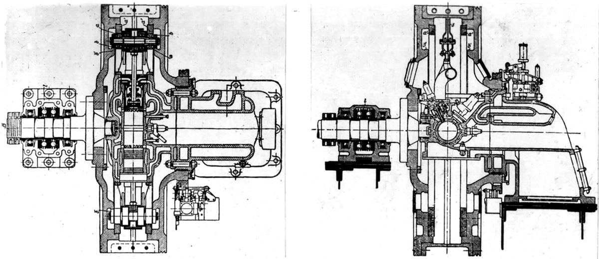
Section view of the Michel three-crank opposed-piston engine. The crankshafts are marked A, B, and C. Clearly seen are the liquid-cooling (W), scavenging air (S), and exhaust (E) passageways. Note the unique piston head shape that creates a combustion chamber.

The three-cylinder engine had a 15 to 1 compression ratio. The engine’s three pistons converged on a common combustion chamber where a fuel injector was positioned vertically between the upper two cylinders. The piston heads were specially designed to create a combustion space when the pistons came together. Fuel injection started 19 degrees before the exhaust piston reached top dead center and continued for 21 degrees. The engine’s configuration resulted in very efficient combustion due to the high degree of turbulence and thorough mixing of air and fuel.

All three crankshafts rotated in the same direction. There was an additional, projecting crank at the end of each crankshaft. Attached to this crank was a triangular casting that connected the crankshafts together at the rear of the engine. This triangular member drove the generator and the water, oil, and Bosch fuel injection pumps. The fuel injection pump was positioned in the upper V of the engine.

Michel 3-cylinder section

Front and rear section view of the Michel three-cylinder opposed-piston engine. Note on the rear view, the triangular member connecting the three crankshafts and the rectangular scavenging air pump at its center.

A scavenging air pump was situated at the rear of the engine. This air pump was a rectangular frame formed integral with the triangular member that joined the crankshafts. The air pump took advantage of the frame’s rotary motion. The rectangular frame was sealed except for strategically placed passageways. A slide valve formed a partition within the frame and was fixed so that it could only move up and down. As the engine ran, the space within the frame on either side of the slide valve partition alternately expanded and contracted, creating a pumping action. Air was fed from the slide valve at 21-25 psi (1.4-1.7 bar) to the cylinders via internal passageways. Power from the engine was taken from the lower crankshaft.

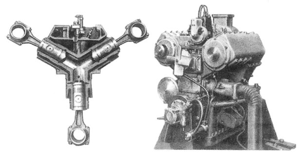
In the early 1930s, Michel relocated to Hamburg, Germany and built a few of his redesigned, three-cylinder, opposed-piston engines. Like the cam engine, the cylinder group was somewhat modular, and additional groups could be added to the design. The engine with the smallest cylinder size had a 1.9 in (47 mm) bore and a 3.1 in stroke (80 mm). This engine had four three-cylinder groups and a total displacement of around 102 cu in (1.7 L) from its 12 cylinders. It produced 60 hp (45 kW) at 2,000 rpm and weighed 616 lb (279 kg).

Michel 3-cylinder

A Michel 3-cylinder group and its engine. This engine has one cylinder group. Note its short length and the single exhaust port of the lower cylinder..

A larger three-cylinder engine was built with a 2.6 in (67 mm) bore and a 4.7 in stroke (116 mm). Each three-cylinder group would displace around 75 cu in (1.2 L) and had an output of around 45 hp. A one cylinder group and a four cylinder group were made. The four cylinder group engine had a displacement of 299 cu in (4.9 L). This engine produced 180 hp (134 kW) at 2,000 rpm and weighed 1,188 lb (539 kg).

Although the engine’s size was not stated, a Michel engine was extensively run in a truck testbed and reportedly gave good results. However, the engine never entered production. The Michel line of engines was supposed to be made under license in the United Kingdom by Tekon Development Ltd and called the Stellar. However, it does not appear that any engines were made.

*Please note, the Hermann Michel discussed in this article is not the Nazi war criminal with the same name.

Michel 12-cylinder opposed piston engine

A Michel engine with four groups of three opposed-piston cylinders. This engine had a total of 12 cylinders. Note the four square exhaust ports on the lower cylinder bank.

Sources:
– “Two-Stroke-Cycle Internal-Combustion Engine” US patent 1,603,969 by Hermann Michel (granted 19 October 1926)
– “Engine, and Particularly Internal Combustion Engine” US patent 1,568,684 by Hermann Michel (granted 5 January 1926)
– “Comments on Crankless Engine Types” NACA Technical Memorandum No. 462, May 1928 (Translated from “Motorwagen” 20 November 1927) 12.8 MB
High Speed Diesel Engines by Arthur W. Judge (1941)
The Modern Diesel fourth edition no date Illiffe & Sons Ltd
New Motoring Encyclopedia (complete work 1937)
Ungewöhnliche Motoren by Stefan Zima and Reinhold Ficht (2010)

Skoda-Kauba V4

Skoda-Kauba V4, SK 257, and V5

By William Pearce

In early 1942, Austrian engineer Otto Kauba had interested the RLM (Reichsluftfahrtministerium or German Ministry of Aviation) in the design of a flying bomb. The RLM founded the Škoda-Kauba Flugzeugbau in German-occupied Prague, Czechoslovakia to produce the aircraft. Kauba was assigned to work out of the Škoda Auto Works, and the aircraft were to be built by the Czech company Avia. Although the flying bomb project was unsuccessful, Škoda-Kauba continued to design a series of small aircraft for the RLM, all of which were built by Avia. His next two designs yielded small and strangely shaped aircraft, but Kauba’s fourth design was a much more refined and sleek aircraft: the V4.

Skoda-Kauba V4

The Argus As 10C-3-powered Škoda-Kauba V4 was a sleek and attractive aircraft. Note the cut-out in the vertical stabilizer that allowed the variable incidence horizontal stabilizer to move.

The Škoda-Kauba V4 was designed to be a single-seat advanced trainer. It was an exceptionally clean low wing aircraft with retractable, wide-track main gear. The V4 employed simple construction and used non-strategic materials, such as steel, wood, and canvas. The wing’s leading edge was swept back and its tubular main spar tapered toward the rounded wingtip. Ribs were welded onto the main spar to form the basic frame of the wing, which was then covered with plywood. The fuselage had a welded steel-tube frame skinned with plywood. The V4 had a variable incidence horizontal stabilizer that was adjusted by the pilot via an electric motor for trim control. The V4 was powered by a 240 hp (179 kW) Argus As 10C-3 inverted, air-cooled, V-8 engine. Provisions were made to mount a single 7.9 mm machine gun.

The V4 had a wingspan of 24 ft 11 in (7.6 m) and a length of 18 ft 4 in (5.6 m). The aircraft’s maximum speed was 261 mph (420 km/h) at altitude and 236 mph (380 km/h) at sea level. Cruising speed was 196 mph (315 km/h). The SK 257’s initial rate of climb was 2,008 ft/min (10.2 m/sec). Its service ceiling was 24,600 ft (7,500 m), and it had a range of 578 miles (930 km). The aircraft weighed 2,249 lb (1,020 kg) empty and 2,756 lb (1,250 kg) loaded.

Skoda-Kauba V4 and SK 257

This image gives a good view of the differences between the V4 and the SK 257 prototype. Note the different wing shape and longer Argus As 410 engine and rear fuselage of the SK 257.

The V4, carrying the registration D-EZWA, exhibited good flying characteristics and performance. Since it was constructed from non-strategic materials, the RLM saw the makings of a good aircraft. However, the desire for more power could not be overlooked. The RLM awarded Škoda-Kauba a contract for the development of a more powerful advanced trainer, designated SK 257. The RLM believed the SK 257 would prepare new pilots for the challenging Messerschmitt Bf 109. Four SK 257 prototypes were ordered.

The SK 257 was very similar to the V4, although slightly longer and powered by a larger engine. The SK 257’s engine was an air-cooled, inverted, V-12 Argus As 410 that produced 485 hp (362 kW). Reportedly, the SK 257 had the same 24 ft 11 in (7.6 m) wingspan as the V4, but its wing had square tips and less sweep. At 23 ft 4 in (7.1 m), the SK 257 was 5 ft (1.5 m) longer than the V4. The aircraft had a maximum speed of 217 mph (350 km/h).

Skoda-Kauba SK 257 accident

Two production Škoda-Kauba SK 257 come to grief. Note the different tail and canopy when compared to the prototype and the absence of gear doors.

The four (some say two) SK 257 prototypes were completed and the first flew in 1943. The aircraft displayed excellent handling and performance. Subsequently, The RLM ordered 1,000 SK 257 trainers for the Luftwaffe. This order was quickly reduced to 100 aircraft. The production aircraft were built at Trenčin on the Biskupice airfield in Slovakia. The production SK 257 aircraft had a simplified square tail, whereas the prototypes had a curved tail. After five examples had been built, their construction was judged to be so poor that they did not pass the Luftwaffe quality control inspections, and the entire order was cancelled.

Undeterred, Kauba designed a fighter based on the V4/SK 257 aircraft. This fighter was designated V5 and was to be powered by a 1,750 hp (1,305 kW) Daimler-Benz DB 603 liquid-cooled inverted V-12 engine. The V5 was intended to out-perform the Focke-Wulf Fw 190 with a maximum speed of 475 mph (765 km/h). It would have a 40 ft (12.2 m) wingspan with two 20 mm cannons in each wing, be 32.8 ft (10 m) long, and weigh 9,920 lb (4,500 kg). However, the V5 progressed no further than a series of wind tunnel models and a full-scale mockup. The RLM was focused on other projects and felt the development of an entirely new piston-engine fighter was a waste of time, resources, and effort.

Skoda-Kauba V5 mock-up

The full scale mockup of the Škoda-Kauba V5 fighter. Note the Škoda-Kauba emblem that was also worn by all the prototypes and derived from the Škoda Auto Works emblem.

The only surviving piece of Škoda-Kauba’s efforts is the left wing, including landing gear, from a SK 257. This artifact is on display at the Vojenský Historický Ústav (Military History Institute) in Prague.

Skoda-Kauba SK 257 wing VHU

Preserved wing of a Škoda-Kauba SK 257 at Vojenský Historický Ústav in Prague. Note the tapered, tubular main spar protruding from the wing. (Vojenský Historický Ústav image)

Sources:
German Aircraft of the Second World War by J. R. Smith and Antony L. Kay (1972/1992)
Československá Letadla [1] 1918-1945 by Václav Němeček (1983)
http://www.histaviation.com/Skoda-Kauba.html and subpages
http://www.vhu.cz/exhibit/kridlo-z-nemeckeho-cvicneho-letounu-sk-257/

Sud-Ouest (SNCASO) SO.8000 Narval

By William Pearce

In the immediate aftermath of World War II, France worked to rebuild its military. Much progress had been made in aviation during the war years, and this was now an area of special focus. The French Navy (Marine Nationale) expressed an interest in a new aircraft that could serve in fighter, interceptor, and ground attack roles. Although other navies were beginning the transition to jet aircraft, the French Navy requested this new aircraft to be piston-powered.

Sud-Ouest SO8000 side

Side view of what is believed to be the first Sud-Ouest SO.8000 Narval, which was actually the second aircraft to fly. This image illustrates the good visibility provided to the pilot by the cockpit’s configuration. Note the radio antenna mast under the cockpit that was unique to the first aircraft.The aircraft is also lacking gear doors.

On 31 May 1946, the Société nationale des constructions aéronautiques du sud-ouest (often abbreviated as SNCASO or shortened to Sud-Ouest) was selected to design this new aircraft and build two prototypes. Arsenal de l’Aéronautique (Arsenal) was selected to develop its power plant. The original plan was to build five prototype aircraft followed by 65 production aircraft. Sud-Ouest moved quickly and designed an unusual single-engine pusher aircraft with twin booms supporting its tail. The aircraft was designated SO.8000 and given the name Narval (Narwhal).

Designed by Jean Dupuy, the SO.8000 was an all-metal aircraft. The inboard leading edge of its wing was sweptback 24 degrees, while the outboard section was sweptback 13.5 degrees and incorporated a dihedral angle. The aircraft had large double slotted flaps to decrease its landing speed for carrier operations. Roll control was achieved by a combination of small ailerons at the wingtips and spoilers. The twin booms extended from the inner wing sections and each supported a fin extending above and below the boom. The horizontal stabilizer spanned between the two tails and was attached near their top. On the second aircraft, which was the first to fly, the elevator was extended beyond the vertical tail fins and incorporated a horn balance.

Sud-Ouest SO8000 front

The first SO.8000 had its pitot tube located on an outrigger by the cockpit and not in the wing leading edge like the second aircraft. This view shows the Narval’s air inlets for its radiator and the air intake for its engine.

The pilot was enclosed in a sliding bubble-style canopy near the front of the aircraft. This configuration provided the pilot with an excellent view. Behind the cockpit and on each side of the aircraft were cooling air intakes for the radiator. After flowing through the radiator, the cooling air exited around the spinner of the eight-blade contra-rotating propellers. The air intake for the Arsenal 12H engine was located on the upper left side of the rear fuselage.

Lacking the time to design and test a completely new engine, Arsenal turned to the German Junkers Jumo 213A as a starting point. Arsenal reworked the Jumo 213 and created the 2,100 hp (1,566 kW) 12H. The 12H was an inverted V-12 with a 5.9 in (150 mm) bore, a 6.5 in (165 mm) stroke, and a displacement of 2,135 cu in (35.0 L). However, more power was desired, and Arsenal increased the 12H’s output to 2,250 hp (1,678 kW). This power increase caused some engine reliability problems. In 1948, the aircraft engine branch of Arsenal was absorbed by the Société nationale d’études et de construction de moteurs d’aviation (SNECMA), and the engine became the SNECMA Arsenal 12H.

Sud-Ouest SO8000 Narval

Another view of the first Narval illustrating its wing sweep and contra-rotating propellers.

The SO.8000 Narval was to be equipped with six 20 mm cannons in its nose. Additionally, underwing hard points would accommodate 2,205 lb (1,000 kg) of bombs. However, it is unlikely that the prototypes were ever armed. The SO.8000 had a 38 ft 7 in (11.75 m) wingspan and was 38 ft 9 in (11.80 m) long. On its tricycle landing gear, the aircraft stood 10 ft 6 in (3.20 m) tall. The Narval had an empty weight of 10,626 lb (4,820 kg) and a loaded weight of 15,432 lb (7,000 kg). The predicted performance of the SO.8000 was a maximum speed of 453 mph (730 km/h) at 24,606 ft (7,500 m) and a landing speed of 96 mph (155 km/h). The aircraft had an estimated 2,796 mi (4,500 km) range at 329 mph (530 km/h).

Sud-Ouest SO8000 rear

This image provides a good view of the first SO.8000’s elevator. Note how the horizontal stabilizer does not extend beyond the tail fins.

Most sources indicate that the second prototype (registered as F-WFKV) was completed and flew first, taking to the air on 1 April 1949 with Jaques Guignard at the controls. The first prototype’s first flight was on 30 December 1949 with Roger Carpentier (some sources say Jaques Guignard) as the pilot. The SO.8000 experienced numerous problems during its flight test program. The aircraft handled poorly and possessed some undesirable control characteristics, such as instability at low speed. Efforts were made to improve control and performance, including replacing the Chauvière contra-rotating propellers with a Rotol unit, but the results were still not satisfactory. In addition, the 12H engine proved to be unreliable. The flight tests revealed that the aircraft would not achieve its expected performance, and flight evaluations of the SO.8000 at the Centre d’Essais en Vol (Flight Test Center) in January 1950 were mostly unfavorable.

Given the trouble with the aircraft and the dominating performance of jet aircraft, further development of the SO.8000 was halted. A contributing factor in the Narval’s cancellation was the allocation of US Grumman F6F Hellcats and Vought F4U Corsairs to France. The second prototype took its 43rd and final flight on 8 January 1950. The first prototype was only flown twice. Proposals were submitted to convert the aircraft to jet-power as the SO.8010, but no further action was taken. Apparently, both SO.8000 aircraft were scrapped after the program was terminated.

Sud-Ouest SO8000 ground

In contrast to the image above, the elevator of the second SO.8000, which was actually the first to fly, can be seen extending past the tail fin in this view. The radio mast for the second aircraft was located on the back of the aircraft behind the cockpit, and note the pitot tube is on the far wing. In this image, the nose gear door has been attached but the main gear doors have not.

Sources:
The Complete Book of Fighters by William Green and Gordon Swanborough (1994)
French Secret Projects 1: Post War Fighters by Jean-Christophe Carbonel (2016)
Jane’s All the World’s Aircraft 1949-1950 by Leonard Bridgman (1949)
Aircraft Engines of the World 1951 by Paul H. Wilkinson (1951)
http://www.avionslegendaires.net/avion-militaire/sud-ouest-so-8000-narval/

Nordberg 12-cylinder radial diesel

Nordberg Radial Stationary Engine

By William Pearce

In 1889, Bruno V. Nordberg founded the Nordberg Manufacturing Company (Nordberg) in Milwaukee, Wisconsin to build various industrial machines. In the 1910s, the company entered the heavy-duty diesel engine market. Over the years, Nordberg expanded its stationary engine catalog to include engines from 10 hp (7.5 kW) to over 10,000 hp (7,457 kW). To further expand its market, Nordberg developed a line of stationary radial engines in the 1940s.

Nordberg 12-cylinder radial diesel

A 12-cylinder Nordberg diesel radial engine. This engine displaced 29,556 cu in (484.3 L) and produced around 2,000 hp (1,500 kW). Note the fuel injector in the center of the cylinder head.

The Nordberg radial offered several advantages over the stationary inline engines that were the current standard. With its cylinders horizontal, the Nordberg radial’s output shaft was in a vertical position. Although the engine was built primarily to generate power for the electrolytic reduction of aluminum, its arrangement was perfect for pumping applications. In addition, the configuration of the radial made it more compact and much lighter than a comparative inline engine. The Nordberg radial took up about half the space of an equally powerful inline engine and could be installed on a much lighter foundation.

The Nordberg radial was first introduced in 1947. The first engines were spark-ignition natural gas burning units that quickly established themselves as reliable and economical. These engines had two spark plugs located in the cylinder head. A single cam on the crankshaft actuated a gas valve for each cylinder. This gas valve allowed the natural gas into the incoming scavenging air for the cylinder.

Nordberg continued to develop the radial as its use spread to central power stations and various pumping applications, primarily for flood control and at sewage treatment plants. Nordberg soon developed a diesel version of the engine and a version that could run on a mixture of diesel and natural gas, which Nordberg dubbed Duafuel. The Duafuel engine could run on 100% diesel or as little as 5% diesel and 95% natural gas. This flexibility allowed the engine to operate with the most economical fuel mixture possible. In the diesel and Duafuel engines, the single cam now actuated a fuel pump for each cylinder, and the diesel fuel injector was in the center of the cylinder head.

Nordberg 12-cylinder radial spark ignition

A number of Nordberg 12-cylinder spark-ignition radial engines are loaded into a barge in Milwaukee, Wisconsin. Note the two spark plugs in the cylinder head. This image also shows the base of the engine that would extend under the operating floor.

A later development was the addition of two turbochargers and intercoolers that increased the engine’s thermal efficiency while decreasing its fuel consumption. It is not clear whether or not the turbochargers were available for all engine types or just for the spark-ignition engines.

The Nordberg radial was a two-stroke engine with a 14 in (356 mm) bore and a 16 in (406 mm) stroke. Each cylinder displaced 2,463 cu in (40.4 L). There was an 11-cylinder (RTS 1411) and a 12-cylinder (RTS 1412) version of the radial engine, displacing a total of 27,093 cu in (444.0 L) and 29,556 cu in (484.3 L) respectively. The 11-cylinder engine was 12.125 ft (3.70 m) in diameter while the 12-cylinder was 13 ft (4.96 m). The engines had an operating speed of 400 rpm. Output varied depending on the engine’s configuration. A 11-cylinder spark-ignition engine was rated at 1,340 hp (1,100 kW), an 11-cylinder diesel was rated at 1,655 hp (1,235 kW), and a 12-cylinder diesel was rated at 2,125 hp (1,585 kW).

The 11-cylinder and 12-cylinder engines both had a crankshaft cast of high tensile alloy iron. The crankshaft had upper and lower main bearings. Neither engine had a master connecting rod; all connecting rods were of the articulated type.

Nordberg 11-cylinder radial crankshaft

The crankshaft arrangement of the 11-cylinder Nordberg radial engine. All the connecting rods are attached to the master gear, which is not labeled in the image.

Each of the 11-cylinder engine’s connecting rods was attached to a large master gear via a knuckle pin. The master gear sat just above the connecting rods and was mounted on the crankshaft’s single crankpin. The master gear did not rotate, being restrained by two pinions and a stationary gear. The lower pinion rode on the master gear opposite the crankpin. The lower pinion was mounted on the same shaft as the upper pinion, which engaged a stationary gear at the top of the engine. Since the master gear was mounted on the crankpin, it moved in a circular motion with the crankshaft, and each knuckle pin subsequently moved in a circular motion. This design eliminated the need for a master connecting rod and provided good balance.

The 12-cylinder engine did not employ a master gear like the 11-cylinder engine. Instead, each connecting rod was attached to a master bearing via a knuckle pin. The master bearing was mounted on the crankshaft’s single crankpin. Two opposing connecting rods were rigidly connected to extended knuckle pins. Each of these extended knuckle pins carried a small restraining crank. The two restraining cranks were connected via a larger restraining link. This linkage prevented the master bearing from rotating but allowed it to move in a circular motion, like the master gear in the 11-cylinder engine. The 12-cylinder’s crankshaft arrangement was designed by Donald I. Bohn and awarded US patent 2,584,098 on 29 January 1952.

Nordberg 12-cylinder radial crankshaft

The crankshaft arrangement of the 12-cylinder Nordberg radial. Compare with the image of the 11-cylinder’s crankshaft.

The Nordberg radial engine had a single-piece cast iron crankcase and sub-base. Each cylinder was drawn to the crankcase by four long studs. The cylinders had intake ports positioned on the top side of the cylinder wall and exhaust ports on the lower side. The exhaust ports were closer to the head than the intake ports to allow for good cylinder scavenging. Either an electric or a geared blower pressurized the intake air and aided cylinder scavenging. The exhaust was expelled into a manifold located under the operating floor. The cylinders fired one right after another in successive order.

By the mid-1950s, the Aluminum Company of America (Alcoa) had 220 normally scavenged and 22 supercharged Nordberg radial engines installed in its Port Lavaca, Texas aluminum plant. Combined, these engines could produce 475,000 hp (354,207 kW). The engines were arranged in seven powerhouses, consisting of around 40 engines each. Kaiser Aluminum used 80 Nordberg radial engines in its reduction plant in Chalmette, Louisiana, accounting for 150,000 hp (111,885 kW).

Various smaller engine installations occurred in municipal power plants and pumping stations. In 1956, a 12-cylinder Nordberg radial engine was put into service at the municipal power plant in Winterset, Iowa. This engine is still in service as of 2016. In 1957, three 11-cylinder Nordberg radials were installed in the South Florida Water Management District Pump Station S-9, just west of Southwest Ranches, Florida. Each of these engines powered a pump with a 143,625 gpm (543,679 L/m) capacity. These Nordberg radials were retired in 1989 because of the scarcity of spare parts. One of the engines is currently on display at John Stretch Park in Lake Harbor, Florida. Nine 12-cylinder engines were installed in the Wastewater Treatment Plant at Deer Island (Boston), Massachusetts in 1968. Over five years, each engine had averaged 22,315 hours of operation. This equates to the engines running 12.25 hours a day, every day, for five years.

Nordberg 11-cylinder radial engines Alcoa

Forty Nordberg 11-cylinder spark-ignition radial engines in one of seven powerhouses at the Aluminum Company of America plant in Port Lavaca, Texas.

Over time, the engines did have problems. Because the cost to inspect the crankshaft was practically as much as replacing it, Alcoa adopted a policy to forgo inspections and run the engine until the crankshaft broke—and break it would. A number of other operators followed suit. Another issue was with excessive piston wear. The Deer Island installation had constant issues with various parts breaking, resulting in engines being off-line for extended periods. Since Nordberg was the sole supplier of parts and it could take some time for replacement parts to be supplied, cannibalism of engines occurred when more than one unit was down.

In 1970, the Nordberg Manufacturing Company was purchased by the Rexnord Corporation, also of Milwaukee, Wisconsin. In 1973, Nordberg/Rexnord stopped manufacturing diesel engines and parts. This, combined with the difficulties experienced by several operators, led to the phase out of the Nordberg radial engine. In 1987, Rexnord was purchased by Banner Industries of Cleveland, Ohio, and Nordberg was renamed Nordberg Inc. In 1989, Nordberg Inc was sold to the Finish company, Rauma-Repla Oy. At his time, Nordberg Inc manufactured mining equipment, mainly rock crushers. Through mergers, Rauma-Repla Oy became the Metso conglomerate in 1999. Nordberg Inc was renamed Metso Minerals Milwaukee, and continued to manufacture equipment until the factory was shut down on 30 June 2004. The closure ended 115 years of industrial machine manufacture.

Nordberg 11-cylinder radial engine FL

An 11-cylinder Nordberg diesel radial engine retired from pumping duties and now on display at John Stretch Park in Lake Harbor, Florida. (Image by Daniel Holth via Wikimedia Commons)

Sources:
Diesel and High Compression Gas Engines – Fundamentals by Edgar J. Kates (1954)
Nordberg Radial Engines (1958)
– “Radial Engine,” US patent 2,584,098 by Donald I. Bohn (awarded 29 January 1952)
http://www.oldengine.org/members/diesel/Nordberg/Nordmenu.htm and sub-pages
https://ssl.panoramio.com/photo/14133737
http://archive.org/stream/wastewaterengine10mass/wastewaterengine10mass_djvu.txt
https://cityofwinterset.org/electric-utility-information/