By William Pearce
The British firm Armstrong Siddeley Motors (ASM) was formed in 1919 when Armstrong Whitworth (founded in 1847) purchased Siddeley-Deasy (founded in 1912). Prior to the merger, both Armstrong and Siddeley were active in the automotive and aeronautical fields. Siddeley first began manufacturing aircraft engines in 1915 under a contract to build the Royal Aircraft Factory’s RAF 1A engine. In 1916, Siddeley had built its first aircraft engine—the Puma—which was developed from the B.H.P. (Beardmore-Halford-Pullinger) six-cylinder engine. The Puma was the first in a long line of engines that were produced by ASM into the 1940s and named after cats (felines)—the last being the Cougar of 1945.
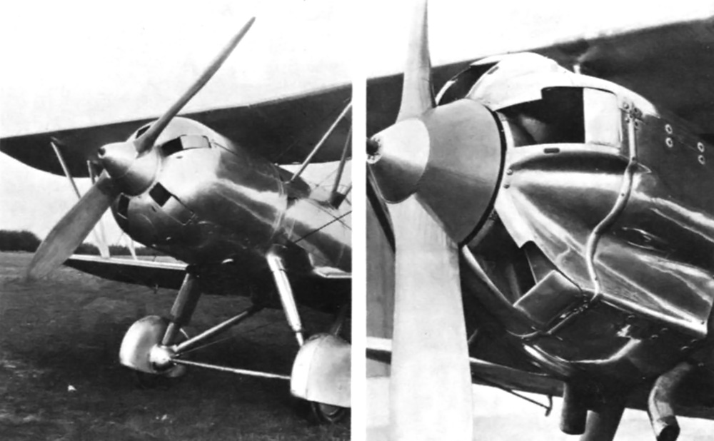
Two versions of the cowling used to cover the 15-cylinder Armstrong Siddeley Hyena installed in an Armstrong Whitworth A.W.XVI (A.W.16). The cowling on the right is illustrative of the Hyena’s inline radial cylinder arrangement.
In 1932, ASM worked to develop a new line of air-cooled, radial engines. These engines would be a design departure from their existing cat-engines, so they decided to name the engines after dogs (canines). Unfortunately, none of these engines were successful, and information about them is frustratingly hard to find and occasionally contradictory. To add to the confusion, some of the engine names were used more than once, and the engines possess many of the same characteristics.
The first engine of the new dog-series was the Mastiff (this name was used again later). This engine was built in 1932 and was a large radial engine with two rows of seven cylinders. The specifications of the 14-cylinder engine are currently not known. In reviewing a photo (that is unfortunately not publishable) of the Mastiff, the engine closely resembles a larger version of the 1,996 cu in (32.7 L) ASM Tiger in appearance and construction. The Mastiff was supercharged and had a one-piece crankcase and gear reduction. A cam ring at the front of the engine acted on pushrods that actuated each cylinder’s two valves. One Mastiff was built for Italy, but it is not known if the engine was ever tested.

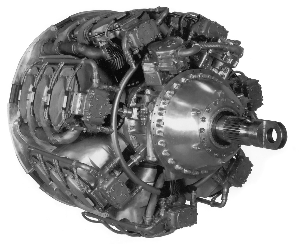
This photo gives a good view of the 21-cylinder Armstrong Siddeley Deerhound I’s configuration. Note the engine’s inline radial layout and the vertical shaft in front of each cylinder bank to drive the overhead camshaft.
The second dog-engine was the Hyena. The Hyena’s 15 air-cooled cylinders were arranged in three rows of five. Even more unusual than the three-row arrangement was the fact that the cylinder rows were inline rather than staggered. Between each of the engine’s five cylinder banks was a camshaft that acted upon short pushrods to actuate the two valves per cylinder. The camshafts were geared to the crankshaft.
The Hyena had a 5.39 in (137 mm) bore and a 4.92 (125 mm) stroke. The engine’s total displacement was 1,687 cu in (27.64 L), and it produced 620 hp (462 kW) at 2,250 rpm. The Hyena was first run in 1933 and was installed in an Armstrong Whitworth A.W.XVI (A.W.16) biplane fighter later that year. The Hyena-powered A.W.XVI (registered as G-ABKF) first flew on 25 October 1933. The basic engine proved itself to be mechanically sound but rather heavy for its power. Issues were encountered with cooling the rear cylinders. This led to a number of different engine cowlings being tried, but the overheating issues persisted. Eventually, further development of the Hyena was abandoned, and only one or two engines were built. The Hyena was proposed to power the A.W.21 and A.W.28 fighters, but these projects did not proceed past the design stage.
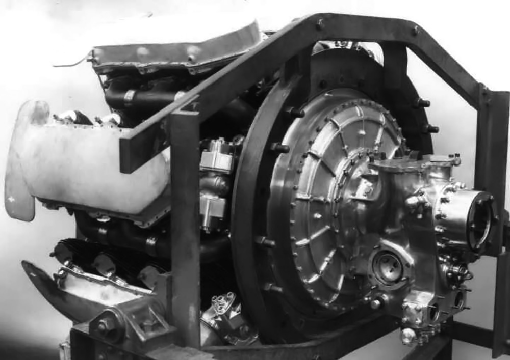
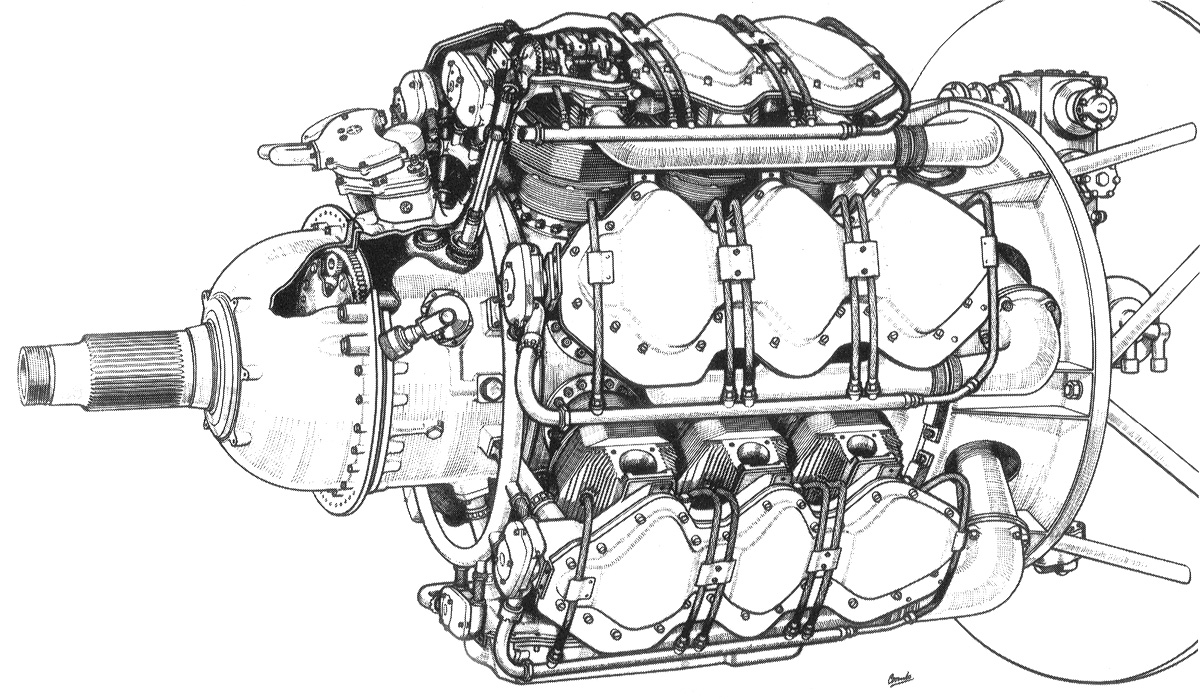
This rear view of the Deerhound I shows the supercharger housing with intake manifolds leading to each bank of cylinders.
Lessons learned from the Hyena were applied to the next dog-engine: the Deerhound. Led by Lt. Col. F. L. R. Fell, the design of the Deerhound was underway by late 1935, and it retained the inline radial cylinder configuration of the Hyena. However, the Deerhound had two addition cylinders for each row, making three rows of seven cylinders. Each cylinder bank of the Deerhound used a single overhead camshaft to actuate each cylinder’s two valves. The camshafts were driven from the crankshaft by a vertical shaft at the front of the engine. The Deerhound had a single-stage, two-speed supercharger and a propeller reduction gear of .432.
The 21-cylinder Deerhound had a 5.31 in (135 mm) bore and a 5.00 in (127 mm) stroke. The engine displaced 2,330 cu in (38.18 L) and had a forecasted output of 1,500 hp (1,119 kW). The Deerhound was seen as insurance against the potential failure of the Bristol Hercules engine then under development. The designers of the Deerhound would have preferred to create a liquid-cooled engine in the 1,500 hp (1,119 kW) class, but ASM management (John Siddeley) insisted on air-cooling. One of the engine’s designers, W. H. “Pat” Lindsey, stated the engine was “old-fashioned” and did not possess many then-modern refinements.

This photo shows five Deerhound engines in various stages of assembly. Most likely, all of the engines are Deerhound Is, but it is possible one is a Deerhound II. From left to right, the engines appear to be numbered D1, D5, D3, D4, and D2. The engine marked D5 is definitely a Deerhound I.
The Deerhound was first run in 1936, and it was not long before cooling and other problems were encountered. Most likely, five engines were built, and the last achieved 1,370 hp before it failed. In 1937, the ASM board tasked Fell to redesign the engine to cure its ills. The redesign resulted in the Deerhound II, which will be described later. The Deerhound was proposed for the Armstrong Whitworth A.W.42 heavy bomber.
Another engine from 1935 was the Terrier. The Terrier was a two-row radial engine in which each row had seven cylinders. Again, specifics of the engine’s configuration are not available, but most likely the Terrier was effectively a two-row, 14-cylinder Deerhound. Retaining the Deerhound’s 5.31 in (135 mm) bore and a 5.00 in (127 mm) stroke, the engine would have a displacement of 1,553 cu in (24.45 L). The Terrier had a 6.6 to 1 compression ratio.

An Armstrong Siddeley Deerhound II partially assembled. The front of the engine, gear case, and valve covers have all be redesigned from that used on the Deerhound I. Note the overhead camshaft and valve arrangement visible on the upper cylinder bank.
Like the Deerhound, the Terrier had a single-stage, two-speed supercharger. The engine produced a maximum of 550 hp (410 kW) at 2,700 rpm for takeoff, 510 hp (380 kW) at 2,100 rpm at 6,500 ft (1,981 m), and 476 hp (355 kW) at 3,100 rpm at 14,700 ft (4,481 m). Normal outputs were 470 hp (350 kW) at 2,700 rpm at 5,000 ft (1,524 m), and 450 hp (336 kW) at 2,700 rpm at 12,000 ft (3,658 m). The Terrier was proposed for a number of projects including the Armstrong Whitworth F.9/35 turret fighter proposal, the Blackburn M.15/35 torpedo bomber proposal, and the Avro 672 and 675 multi-role aircraft designs. None of those projects were built, and work on the Deerhound prevented the Terrier from being constructed.
Also in 1935, the Whippet was designed. Specifics of the Whippet are not available, but the 250 hp (186 kW) engine may have had two rows of seven cylinders with a bore and stroke of around 4.02 in (102 mm). That cylinder size would give the engine a total displacement of around 712 cu in (11.67 L). The Whippet did not proceed beyond the design phase.
The next engine design was initiated around 1936 and was for the Wolfhound (this name was used again later). The inline radial Wolfhound was an outgrowth of the Deerhound and had four rows of seven cylinders. Specifics of the engine are not available. However, 28 cylinders with the Deerhound’s 5.31 in (135 mm) bore and 5.00 in (127 mm) stroke would displace 3,106 cu in (50.90 L) and produce around 1,800 hp (1,342 kW). The Wolfhound did not make it off the drawing board.
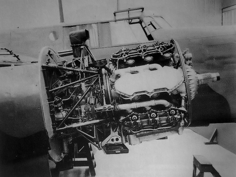
A Deerhound II engine installed in an Armstrong Whitworth A.W.38 Whitley bomber. Note the relatively small diameter of the engine compared to that of the firewall. The 44 in (1.12 m) diameter Deerhound replaced the 51 in (1.29m) diameter Armstrong Siddeley Tiger that was originally installed in the Whitley II.
In 1937, the Deerhound was redesigned and became the Deerhound II. The engine’s configuration changed little. However, refinements were made, and the cylinder bore was increased from 5.31 in (135 mm) to 5.51 in (140 mm). The stroke was unchanged, but the larger bore increased the engine’s displacement by 175 cu in (2.88 L), bringing the total displacement to 2,505 cu in (41.06 L). The engine’s forecasted output was still 1,500 hp (1,119 kW). The Deerhound II had a 6.75 to 1 compression ratio and was 44 in (1.12 m) in diameter. Extensive baffles were installed around the cylinders to help direct air flow and cool the rear cylinders.
The Deerhound II was first run in 1938, but more issues were encountered, including a broken crankshaft during a type test in October 1938. Fell and his team were under immense pressure from the ASM board to fix the engine’s issues. Two Deerhound II engines were installed in an Armstrong Whitworth A.W.38 Whitley bomber (serial no. K7243) for flight tests, and the aircraft first flew in January 1940. Fell’s contract with ASM was not renewed when it expired on 9 February 1939. Lindsey temporarily took over Deerhound development until Stewart S. Tresilian was brought on staff in mid-1939.

Any aerodynamic advantages achieved by the close-fitting cowling covering the Deerhound engine installed on the Whitley must have been undermined by the bulbous cooling-air intake under and the large induction scoop above the engine. This Whitley was eventually lost, but through no fault of the engines.
Although the date is not recorded, the engine did achieved and output of 1,500 hp (1,119 kW) at 2,975 rpm with 5 psi (.34 bar) of boost. On the Whitley bomber, the engines were housed in special nacelles. Cooling air was taken in under the spinner and directed from the rear of the engine forward through the cylinders. However, engine cooling issues persisted, and the designers believed increasing the cooling fin area of the cylinders would resolve the problem.
Flight testing continued until 6 March 1940 when the Deerhound II-powered Whitley bomber was lost on takeoff, killing all three people on board. The crash was attributed to an improperly set trim tab and had nothing to do with the engines. With the testbed destroyed, ASM decided to curtain development of the Deerhound II and focus on an improved version that would cure the overheating issues. The new engine, the Deerhound III, will be described later. Five Deerhound II engines were built.
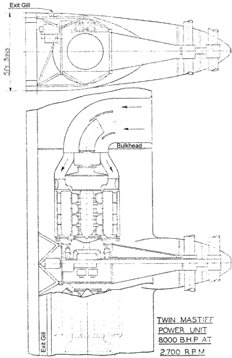
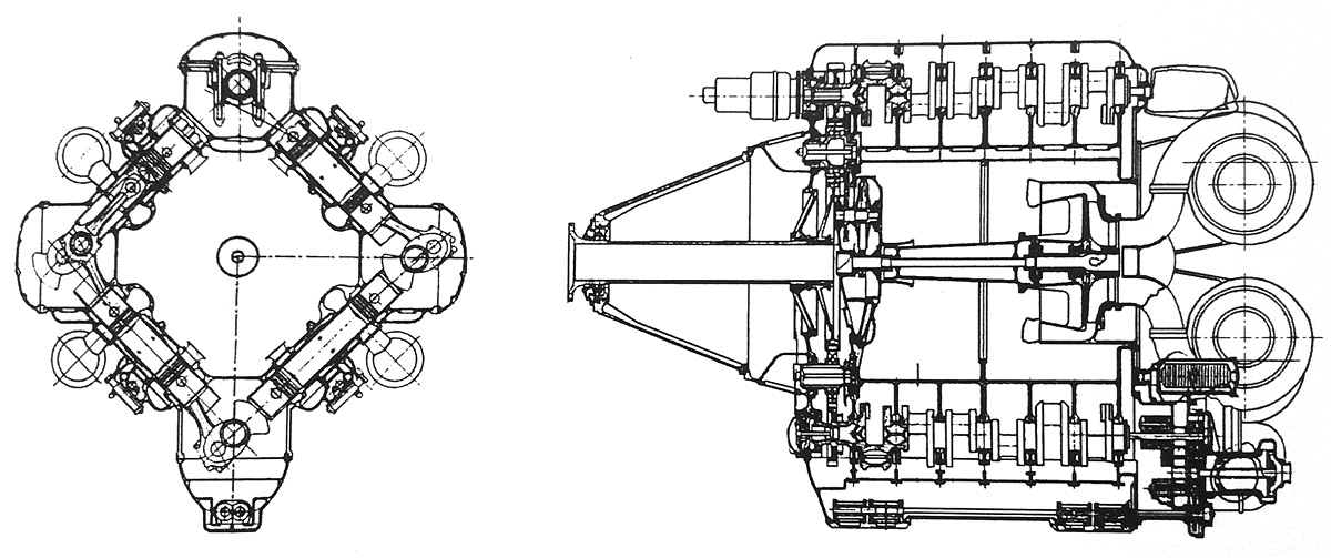
This drawing illustrates a coupled arrangement for two 36-cylinder Armstrong Siddeley Mastiff engines. The engine’s nine banks of four cylinders can be deduced from the drawing. A similar arrangement was purposed with two Deerhound engines.
In 1937, the Boarhound was designed. This engine possessed the larger 5.51 in (140 mm) bore of the Deerhound II and had a longer 6.30 in (160 mm) stroke. The real design change was the engine’s layout—the Boarhound had three inline rows of nine cylinders. With its 27 cylinders, the Boarhound displaced 4,058 cu in (66.50 L). Its initial and rather conservative estimated output was 2,300 hp (1,715 kW) at 2,700 rpm. The Boarhound had a diameter of 51 in (1.30 m). With all resources focused on the Deerhound, the Boarhound was never built.
Around 1938, the Mastiff name was resurrected and given to a further development of the Boarhound. The new Mastiff had four inline rows of nine cylinders. While the cylinder’s bore was still 5.51 in (140 mm), the stroke was lengthened to 6.69 in (170 mm). The 36 cylinders of the Mastiff engine displaced an impressive 5,749 cu in (94.21 L), and output was estimated at 4,000 hp (2,983 kW). Like the Boarhound, the Mastiff was not developed.
In 1940, Tresilian went to work on the Deerhound III to create an engine free from the issues experienced with the original Deerhound and the Deerhound II. The Deerhound III possessed the same bore, stroke, displacement, and 44 in (1.12 m) diameter as the Deerhound II. However, the engine was essentially redesigned, and its output was increased to 1,800 hp (1,342 kW). The engine was first run in late 1940. High-power tests revealed detonation issues with the first row of cylinders, but some sources state the engine did achieve 1,800 hp (1,342 kW) on the dyno. An updated design, the Deerhound IV, was proposed but never built. Only one Deerhound III was built.
This picture shows the sole Armstrong Siddeley Deerhound III engine. Again, revisions to the front of the engine, gear reduction, and valve covers can easily be seen. Reportedly, this engine survived into the 1970s.
In mid-1941, the Wolfhound name was reused for a new Tresilian-designed engine. The new Wolfhound had four inline rows of six cylinders in a flattened X configuration. The 24-cylinder engine had a 5.91 in (150 mm) bore and a 5.51 in (140 mm) stroke. Total displacement was 3,623 cu in (59.38 L), and the engine was to produce 2,600–2,800 hp (1,939–2,088 kW) at 2,800 rpm. The engine had a two-stage supercharger and was designed to power contra-rotating propellers.
In October 1940, a bombing raid severely damaged the Armstrong Siddeley Aero Development shop and destroyed several Deerhound engines. Another raid on 8 April 1941 further damaged the shop and set engine development back even more. ASM dog-engine development continued at a slow pace until October 1941, when the British Ministry of Aircraft Production (MAP) cancelled further work. The ASM dog-engines would not be ready in time to be of any use in the war, and the MAP wanted the company to focus on turbine engines (ASM named theirs after snakes). The sole Deerhound III engine was thought to have survived into the 1970s, but there are no known ASM dog-engines currently preserved.
Drawing of the Armstrong Siddeley Deerhound IV engine that was never built. Even if this design from 1941 proved successful, it would not have been developed in time to see much use during World War II.
Sources:
– Armstrong Siddeley — the Parkside Story 1896–1939 by Ray Cook (1988)
– Parkside: Armstrong Siddeley to Rolls-Royce 1939–1994 by Roy Lawton (2008)**
– Sectioned Drawings of Piston Aero Engines by Lyndon Jones (1995)**
– Armstrong Whitworth Aircraft since 1913 by Oliver Tapper (1973)
– British Secret Projects: Fighters & Bombers 1935–1950 by Tony Buttler (2004)
– British Piston Aero-Engines and Their Aircraft by Alec Lumsden (1994/2003)
– http://www.designchambers.com/wolfhound/index.htm#Articles (and pages therein)
– http://www.secretprojects.co.uk/forum/index.php?topic=5580.0
**Rolls-Royce Heritage Trust books that are currently in print and available from the Rolls-Royce Heritage Trust site.