By William Pearce
In the early 1930s, Charles H. Zimmerman became determined to design a low-aspect ratio, flying wing aircraft with a discoidal planform. The wing would have a short span and make up the aircraft’s fuselage. Zimmerman believed that large, slow-rotating propellers placed at the tips of the aircraft’s wings would cancel out wingtip vortices, provide uniform airflow over the entire aircraft, and effectively increase the aircraft’s span. In addition, the propellers would provide continuous airflow over the aircraft’s control surfaces even at very low forward velocities. The propellers were counter-rotating; viewed from the rear, the left propeller turned counterclockwise and the right propeller turned clockwise. The envisioned aircraft would be able to execute short takeoffs and landings, maintain control at very low speeds, and have a high top speed. Zimmerman’s ultimate goal was a high-speed aircraft that could ascend and descend vertically and could hover.

Drawings from Charles Zimmerman’s 1935 patent showing his low-aspect ratio, flying wing aircraft. Note the three occupants lying in a prone position. The aircraft’s layout was very similar to the Vought V-173. The power transfer shaft (22) can been seen connecting the two propeller shafts.
While working at the National Advisory Committee for Aeronautics (NACA), Zimmerman won a design competition in 1933 for a light, general aviation aircraft. However, his low-aspect ratio design was deemed too radical to be built. Undeterred, Zimmerman designed a three-place aircraft in which the occupants lay in a prone position. Zimmerman called this aircraft the Aeromobile. The aircraft’s propellers were forced to rotate at the same speed via a power cross shaft that linked the engine’s propeller shafts together. Each engine could be disconnected from its respective propeller shaft in the event of an engine failure. The power cross shaft would distribute power from the functioning engine to both propellers.
To test his theories, Zimmerman and some friends built a small proof-of-concept aircraft based on the three-place design. The aircraft had a short 7 ft (2.1 m) wingspan and was powered by two 25 hp (19 kW), horizontal, two-cylinder Cleone engines. Despite several attempts, the aircraft was unable to takeoff. The difficulties were caused by an inability to synchronize the propellers, as the power cross shaft was omitted due to the aircraft’s small size.

The proof-of-concept aircraft built to test Zimmerman’s theories. This image illustrates the aircraft’s 7 ft (2.1 m) wingspan. Due to trouble with synchronizing the engines/propellers, the aircraft was not flown.
Following the unsuccessful trials of small aircraft, Zimmerman took a step back and turned to models. By 1936, he had a rubber band-powered scale model with a 20 in (508 mm) wingspan routinely making successful flights. Others at NACA reviewed Zimmerman’s work and encouraged him to seek financial backing from the aviation industry to further develop his designs—as an individual, his efforts to interest the US Armed Forces had not been successful. Zimmerman found support from Vought Aircraft and was hired on to continue his work in 1937.
Again, the radical nature of Zimmerman’s designs made the establishment question their worth. The US Army Air Corps turned down various proposals, but the US Navy could not overlook the fact that a short wingspan fighter with a short takeoff distance, a very low landing speed, and a high top speed would be ideal for carrier operations. In fact, such an aircraft could operate from just about any large ship. In 1938, the Navy funded the Vought V-162, which was a large model to further test Zimmerman’s ideas. The model was powered by electric motors and took two people to operate. The model sufficiently demonstrated Zimmerman’s design, and the Navy contracted Vought to build a full-size test aircraft on 4 May 1940. The aircraft was designated V-173 by Vought and was given Bureau Number (BuNo) 02978 by the Navy.

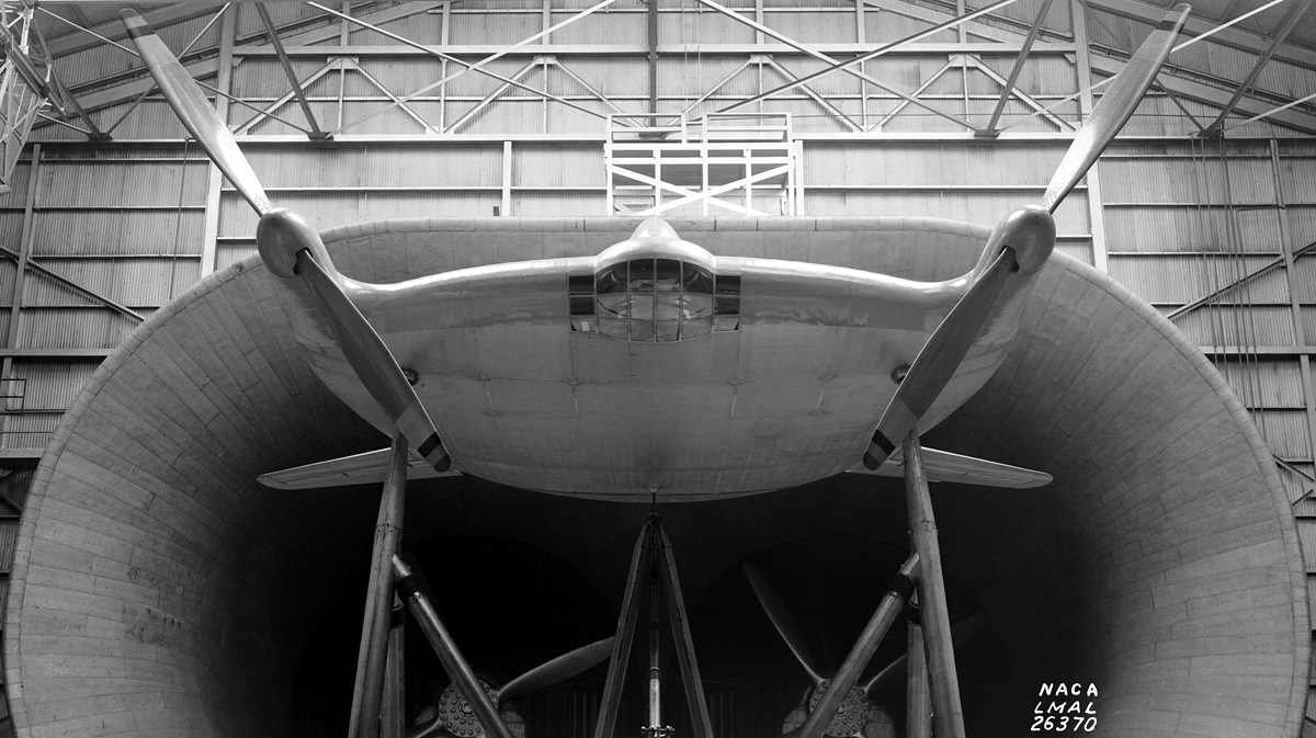
The Vought V-173 in the Langley wind tunnel. Note the forward rake on the two-blade propellers. The rake (or cone angle) was adjustable, and three-blade propellers of the same type were soon fitted to the aircraft. (Langley Memorial Aeronautical Laboratory / NASA image)
The airframe of the Vought V-173 was made mostly of wood, but the forward cockpit structure and propeller nacelles were made of aluminum. The front part of the fuselage back to the middle of the cockpit was covered with wood, and the rest of the aircraft was fabric-covered. Originally, the pilot was to lie in a prone position, but this was changed to a more conventional, upright seat. The lower leading edge of the aircraft had glazed panels to improve visibility from the cockpit while the V-173 was on the ground. Cockpit entry was via a hatch under the aircraft, but the canopy also slid back. Housed in the aircraft’s fuselage were two 80 hp (60 kW) Continental C-75 engines. Most sources list the engines as Continental A-80s, but C-75s were actually installed in the aircraft. The 80 hp (60 kW) rating was achieved through the use of fuel injection. The C-75 was a flat, four-cylinder, air-cooled engine that displaced 188 cu in (3.1 L). One engine was on each side of the cockpit. The engines were started by pulling a handle through an access panel under the aircraft. Each engine had a cooling fan attached to its output shaft, and engine cooling air was brought in through inlets in the aircraft’s leading edge. The air exited via flaps in the upper fuselage.
Via shafts and right angle drives, the engines powered two 16 ft 6 in (5.06 m), three-blade, wooden propellers at around .167 times engine speed. The variable-pitch propellers turned around 450 rpm at maximum power (2,700 engine rpm) and around 415 rpm at cruise power (2,500 engine rpm). The individual blades could articulate (flap) automatically to compensate for side gusts and uneven loading. The blades were hinged inside the propeller hub in which hydraulic dampers limited their articulation. The rake (or coning) angle of the blades could be adjusted on the ground. This moved the tips of the blades either forward or aft relative to the propeller hub.
Underside view of the V-173 shows the windows in the aircraft’s leading edge. The hinge line for the control surfaces between the tails can just be seen near the aircraft’s trailing edge. The surfaces were omitted when the aircraft first flew, but stabilizing flaps were later installed in their place. (Langley Memorial Aeronautical Laboratory / NASA image)
A power cross shaft that ran just behind the cockpit connected the engine gearboxes. The cross shaft ensured that power was delivered equally between the two propellers, and it also synchronized propeller rpm. A failed engine would automatically declutch from the propeller drive system, and the remaining engine would power both propellers. The left engine was started first and then clutched to the propeller drive system. The right engine was then started and automatically clutched to the propeller drive system after it came up to speed.
Under the V-173 were two very long fixed main gear legs that supported the aircraft at a 22.25 degree angle while it sat on the ground. At the rear of the aircraft were two vertical stabilizers. Attached to each side of the V-173 was a horizontal stabilizer with a surface that acted as both an aileron and an elevator (ailavator or ailevator). The ailavators were not part of the initial V-173 design (and were not on the V-162 model), but early model tests indicated that the flight controls were needed.

View of the V-173 on an early test flight that shows no stabilizing flaps between the tails. Note the deflection angle of the ailavator; the V-173 always flew at a nose-high angle because it was underpowered.
The V-173 had a wingspan of 23 ft 4 in (7.1 m) but was about 34 ft 9 in (10.6 m) wide from ailavator to ailavator. The aircraft was 26 ft 8 in (8.1 m) long and 12 ft 11 (3.9 m) in tall. The V-173 could take off in 200 ft (61 m) with no headwind, and it could lift right off the ground with virtually no roll in a 30 mph (48 km/h) headwind. The aircraft’s top speed was 138 mph (222 mph), and cruising speed was 75 mph (121 km/h). With normal prevailing winds, the V-173 would routinely take off in 20 ft (6 m) and land at 15 mph (24 km/h). The aircraft had an empty weight of 2,670 lb (1,211 kg) and a normal weight of 3,050 lb (1,383 kg). The V-173 only carried 20 gallons (76 L) of fuel in two 10 gallon (38 L) tanks.
In November and December 1941, the V-173 was tested in NACA’s Langley wind tunnel in Hampton, Virginia. The aircraft had its original two-blade propellers, but these were found to be insufficient and were replaced by three-blade units shortly after the tests. Two small control surfaces that made up the trailing edge of the aircraft were present between the tails. However, these were removed before the V-173’s first flight. The Navy was encouraged enough by the wind tunnel tests that they asked Vought to prepare a proposal for a fighter version of the aircraft, which eventually became the Vought XF5U-1.

The V-173 is shown with redesigned ailavators and the stabilizing flaps installed. The cooling air exit flaps can be seen near the cockpit. The two ports forward of each cooling air exit flap were for engine exhaust.
After an extended period of taxi tests, the V-173’s first flight took place on 23 November 1942 at Bridgeport Airport (now Sikorsky Memorial Airport) in Stratford, Connecticut, with Vought test pilot Boone T. Guyton at the controls. Guyton found the aircraft’s controls extremely heavy and thought that he might need to make a forced landing. Fortunately, He had enough control to make a large circuit and land the aircraft after 13 minutes of flight. Adjustments to the propellers were made, and the ailavators were redesigned as all-moving control surfaces with servo tabs. These changes improved aircraft control, but landing the V-173 was still difficult. As it approached the ground, air would get trapped under the aircraft and force the tail up. Subsequently, the nose of the aircraft would drop, causing the V-173 to rapidly descend the last few feet. The aircraft would hit the runway harder than intended and bounce back into the air. After about 40 flights, the two stabilizing flaps were added between the aircraft’s tails. The flaps were larger than the control surfaces tested in the wind tunnel, and they were separated by the tailwheel. When the aircraft was near the ground, air loads acted on spring-loaded struts to automatically deflect the stabilizing flaps up and allow air to escape from under the aircraft.
A number of different pilots, including Charles Lindberg, flew the V-173. Over its flight career, the aircraft did experience a few difficult landings that resulted in minor damage. The most serious issue occurred on 3 June 1943 when Vought-pilot Richard Burroughs made an emergency landing on Lordship Beach, Connecticut. Vapor lock had caused fuel starvation and subsequent engine failure. Immediately after touchdown, Burroughs flipped the V-173 onto its back to avoid hitting a sunbather. No one was injured, and the aircraft was not seriously damaged.
The V-173 undergoing an engine run. The engine cooling air intakes can be seen in the aircraft’s leading edge. The canopy is open, and the cockpit access hatch on the aircraft’s underside is also open. Note that the stabilizing flaps are deflected up and that streamlined fairings have been fitted to cover the wheels.
Overall, the V-173 flew as expected, but it was not entirely like a conventional aircraft. The V-173 was underpowered, and there were unresolved vibration issues caused by the propeller gearboxes and drive shafts. The aircraft made around 190 flights and accumulated 131 hours of flight time.
The V-173 made its last flight on 31 March 1947. The Navy kept the aircraft in storage at Norfolk Naval Air Station, Virginia for a number of years and gave it to the National Air and Space Museum in September 1960. The V-173 was stored at the Paul E. Garber Facility in Suitland, Maryland until 2003, when it was moved to Vought’s Grand Prairie facility near Dallas, Texas for restoration by the Vought Aircraft Heritage Foundation. Restoration was completed in February 2012, and the aircraft was loaned to Frontiers of Flight Museum in Dallas, where it is currently on display.
Zimmerman’s aircraft were given several nicknames during their development: Zimmer’s Skimmer, Flying Flapjack, and Flying Pancake. Test pilot Guyton said that the V-173 could fly under perfect control while maintaining a 45 degree nose-up angle with full power and full aft stick. During the flight test program, the pilots were not able to make the V-173 stall completely or enter a spin. The aircraft rapidly decelerated in sharp turns, and this could prove advantageous in getting on an opponent’s tail during a dogfight. But if the shot were missed, the aircraft could be at a disadvantage because of its decreased speed. The V-173 proved the viability of Zimmerman’s low-aspect ratio, flying wing aircraft concept, provided much information on how to refine the design, and directly contributed to the Vought XF5U-1.

Painstakingly restored by volunteers, the V-173 is currently on display in the Frontiers of Flight Museum in Dallas, Texas. The aircraft is on loan from the National Air and Space Museum until at least 2022. (Frontiers of Flight Museum image)
Sources:
– Chance Vought V-173 and XF5U-1 Flying Pancakes by Art Schoeni and Steve Ginter (1992)
– Aeroplanes Vought 1917–1977 by Gerard P. Morgan (1978)
– “Aircraft” US patent 2,108,093 by Charles H. Zimmerman (applied 30 April 1935)
– “The Flying Flapjack” by Gilbert Paust Mechanix Illustrated (May 1947)
– https://www.youtube.com/watch?v=SSkVC9bC_Mg
– http://www.vought.org/products/html/v-173.html
– http://www.airspacemag.com/history-of-flight/restoration-vought-v-173-7990846/?all
– https://crgis.ndc.nasa.gov/historic/Charles_H._Zimmerman
– http://www.flightmuseum.com/exhibits/aircraft-3/aircraft-3/
– Correspondence with Bruce Bleakley, Director of the Frontiers of Flight Museum