Monthly Archives: April 2018

Lycoming O-1230 front

Lycoming O-1230 Flat-12 Aircraft Engine

By William Pearce

In the late 1920s, the Lycoming Manufacturing Corporation of Williamsport (Lycoming County), Pennsylvania entered the aircraft engine business. At the time, Lycoming was a major supplier of automobile engines to a variety of different manufacturers. Lycoming quickly found success with a reliable nine-cylinder radial of 215 hp (160 kW), the R-680. However, the company wanted to expand into the high-power aircraft engine field.

Lycoming O-1230 front

When built, the Lycoming O-1230 was twice as large as and three times more powerful than any other aircraft engine the company had built. Lycoming essentially achieved the performance goals originally set for the O-1230, but other engine developments had made the O-1230 obsolete by the time it would have entered production.

In 1932, Lycoming became aware of the Army Air Corps’ (AAC) program to develop a high-performance (Hyper) cylinder that would produce one horsepower per cubic inch displacement and enable a complete aircraft engine to produce one horsepower per pound of weight. The AAC had contracted Continental Motors in 1932 to work with the Power Plant Branch at Wright Field, Ohio on developing an engine utilizing Hyper cylinders. The engine type was set by the AAC as a 1,200 hp (895 kW), flat, liquid-cooled, 12-cylinder engine that utilized individual-cylinder construction. The flat, or horizontally-opposed, engine configuration was selected to enable the engine’s installation buried in an aircraft’s wings.

Lycoming-O-1230-Hyper-Cylinder

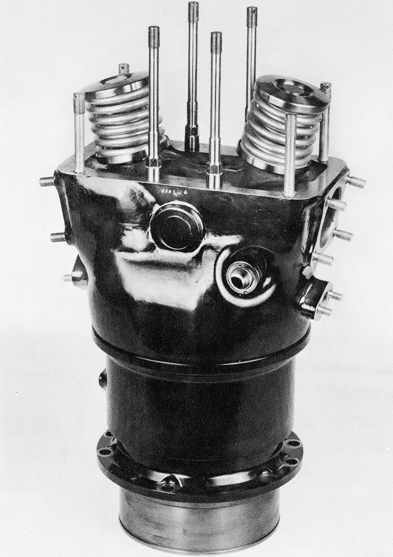
Lycoming’s Hyper cylinder was developed into the cylinder used on the O-1230. Note the studs for attaching the camshaft housing. The intake port and coolant inlet are on the right. The exhaust port and coolant outlet are on the left.

Lycoming saw an opportunity to quickly establish itself as a high-power aircraft engine manufacturer by creating an engine that would satisfy the AAC’s requirements. On its own initiative, Lycoming began work on its own Hyper cylinder with the intent of developing a 12-cylinder engine. Lycoming chief engineer Val Cronstedt was put in charge of the project, and he was assisted by Samuel Hoffman, Clarence Wiegman, and other engineers. The AAC encouraged Lycoming’s involvement and provided developmental support, but the AAC did not initially provide financial support.

Lycoming started serious developmental work on the new engine in 1933. Various single-cylinder test engines were built and tested in 1934. Also in 1934, Hoffman and Wiegman filed for a number of patents that detailed some proposed aspects of the complete 12-cylinder engine. In 1935, the AAC became more interested in the engine and began supporting Lycoming’s efforts. Single-cylinder testing yielded positive results, with the engine passing a 50-hour test in May 1936 and producing 228.7 hp (170.5 kW) at 3,000 rpm from its 102.8 cu in (1.69 L) displacement during maximum performance tests in July 1936. That same year, the AAC contracted Lycoming to build a complete engine. Lycoming had spent $500,000 of its own money and had finalized the design of its engine, which was designated O-1230 (also as XO-1230). Construction of the first O-1230 was completed in 1937, and the engine was ready for endurance testing in December of that year.

The Lycoming O-1230 had a two-piece aluminum crankcase that was split vertically. Six individual cylinders attached to each side of the crankcase. The cylinders were made of steel and were surrounded by a steel water jacket. Each cylinder had a hemispherical combustion chamber with one intake and one sodium-cooled exhaust valve. A cam box mounted to the top of each cylinder bank, and each cam box contained a single camshaft that was shaft-driven from the front of the engine.

Lycoming-O-1230-sectional-and-side

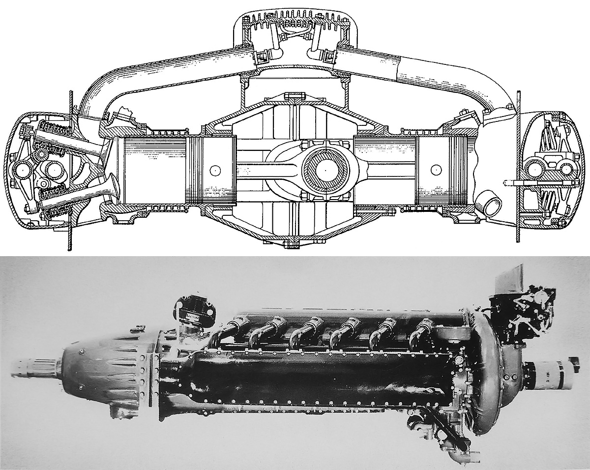
Top: Drawing of the O-1230 from US patent 2,119,879 for a proposed fuel injection system that can be seen in the induction manifold. The drawing shows details of the engine’s construction including the split crankcase and overhead camshaft. Bottom: Intended for installation buried in an aircraft’s wing, the O-1230’s height was kept to a minimum. The long nose case would aid in streamlined wing installations. Note that the supercharger’s diameter was slightly in excess of the engine’s height.

A downdraft carburetor fed fuel into the single-speed, single-stage supercharger mounted at the rear of the engine. The supercharger’s 10 in (254 mm) diameter impeller was driven at 6.55 times crankshaft speed. It provided air to the intake manifold that sat atop the engine. Individual runners provided air to each cylinder from the intake manifold. Lycoming had experimented with direct fuel injection on test cylinders and US patent 2,119,879 was applied for in November 1934 that detailed a fuel injection system for the O-1230. In the patent, fuel injectors would be installed in the removable cover of the intake manifold with one injector spraying into each runner and toward the cylinder. However, it is unlikely that any O-1230 ever used fuel injection.

Exhaust was expelled out the lower side of the cylinders and collected in a common manifold for each cylinder bank. An extended nose case housed beveled planetary gears for the propeller’s gear reduction. The propeller turned at .40 crankshaft speed, with options for a .50 or .333 reduction. On the top of the O-1230, just behind the gear reduction, was the engine’s sole magneto. The magneto was connected to two distributors, each driven from the front of the camshaft drive.

Lycoming-O-1230-mount

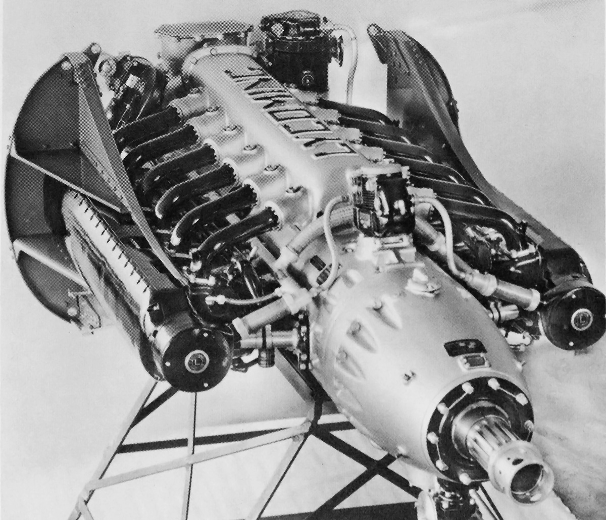
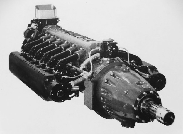
The O-1230 with one style of engine mount that was secured between the camshaft housing and cylinders. Note the induction manifold and individual runners atop the engine.

The O-1230 had a 5.25 in (133 mm) bore and a 4.75 in (121 mm) stroke. The engine’s total displacement was 1,234 cu in (20.2 L), and it had a 6.5 to 1 compression ratio. The O-1230 produced 1,200 hp (895 kW) at 3,400 rpm for takeoff, 1,000 hp (746 kW) at 3,100 rpm for normal operation, and 700 hp (522 kW) at 2,650 rpm for cruise operation. The engine had an overspeed limit of 3,720 rpm for diving operations. The O-1230 was 106.7 in (2.71 m) long, 44.1 in (1.12 m) wide, and 37.9 in (.96 m) tall. The engine weighed 1,325 lb (601 kg).

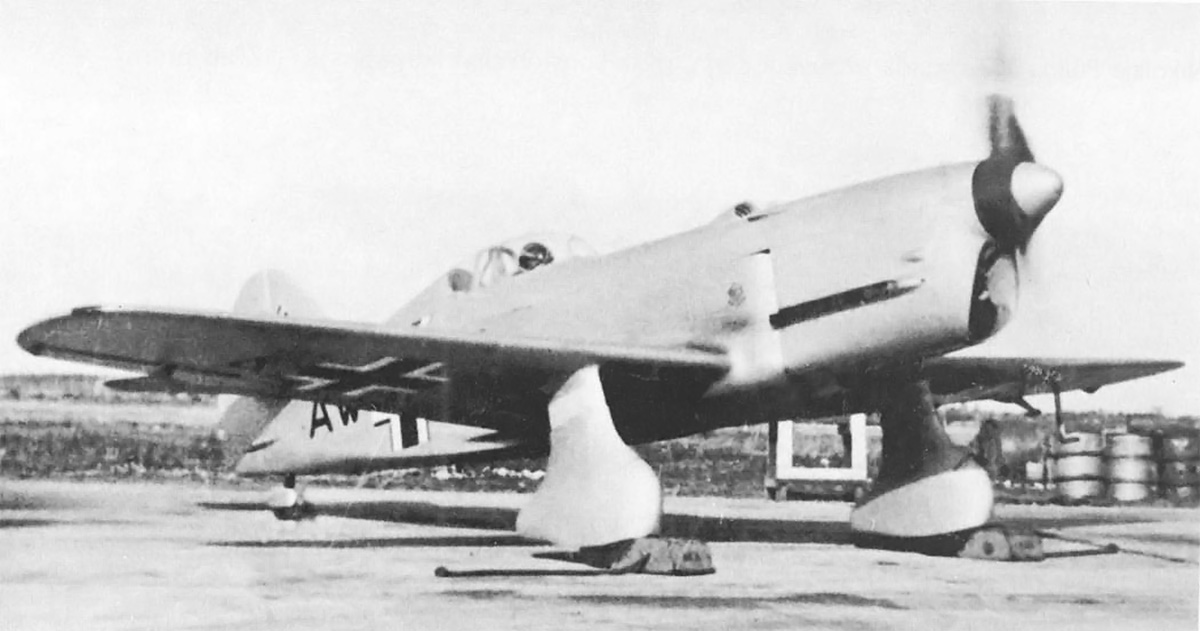
After completing a 50-hour type test in March 1939, the O-1230 was rated at 1,000 hp (746 kW). Continued development pushed the engine’s rating up to 1,200 hp (895 kW). The O-1230 was installed in a Vultee YA-19 attack aircraft that had been modified as an engine testbed and redesignated XA-19A (38-555). Some sources list the designation as YA-19A, but “Y” was typically used for pre-production aircraft, while “X” was for experimental aircraft. The O-1230-powered XA-19A first flew on 22 May 1940, the flight originating at Vultee Field in Downey, California. The aircraft and engine combination were transferred to Wright Field, Ohio in June 1940 and then to Lycoming on 27 March 1941. By this time, the AAC had already moved away from the buried-engine-installation concept and was interested in more powerful engines.

Lycoming O-1230 Vultee XA-19A side

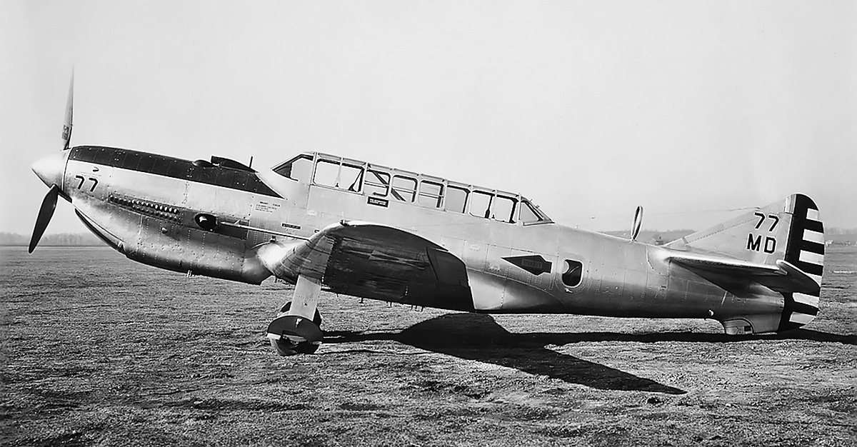
The XA-19A is seen with its Wright Field markings. The scoop above the cowling brought air into the engine’s carburetor. Louvered panels allowed heat generated by the exhaust manifold to escape the cowling. Note the large exhaust outlet. The radiator positioned under the engine added bulk to the O-1230’s installation. The aircraft’s tail was modified to compensate for the larger and longer nose needed to house the O-1230.

While the O-1230’s power output was on par with many of its contemporaries, such as the Allison V-1710, the O-1230 did not offer the same development potential or reliability as other engines. The O-1230 was cancelled in favor of other projects, and the engine was subsequently removed from the XA-19A airframe. The XA-19A was transferred to Pratt & Whitney on 8 August 1941, where an R-1830 was subsequently installed, and the aircraft was redesignated XA-19C.

Lycoming was still interested in developing a high-power engine and used O-1230 components to create the 24-cylinder XH-2470. In some regards, the Lycoming XH-2470 was two O-1230 engines mounted to a common crankcase. Lycoming started initial design work on the engine as early as 1938. An O-1230 is on display at the New England Air Museum in Windsor Locks, Connecticut.

Lycoming O-1230 display

The restored O-1230 on display at the New England Air Museum. The engine’s electric starter is mounted vertically just in front of the supercharger. (Daniel Berek image via Flickr.com)

Sources:
Development of Aircraft Engines and Fuels by Robert Schlaifer and S. D. Heron (1950)
Aircraft Engines of the World 1941 by Paul Wilkinson (1941)
Jane’s All the World’s Aircraft 1942 by Leonard Bridgman (1942)
– “The Evolution of Reciprocating Engines at Lycoming” by A. E. Light, AIAA: Evolution of Aircraft/Aerospace Structures and Materials Symposium (24–25 April 1985)
– “Fuel Injector for Internal Combustion Engines” US patent 2,119,879 by Samuel K. Hoffman and Clarence H. Wiegman (Applied 19 November 1934)
– “Aircraft Prime Movers of the Twentieth Century” by Air Commodore F. R. Banks, Seventh Wings Club ‘Sight’ Lecture (20 May 1970)
– “Vultee Engine-Test Aircraft in World War II” by Jonathan Thompson, AAHS Journal Volume 39 Number 4 (Winter 1994)

VEF I-16 Front right

VEF I-16 Light Fighter Aircraft

By William Pearce

VEF (Valsts Elektrotehniskā Fabrika or State Electro-Technical Factory, often spelled Valsts Elektrotechniskā Fabrika) was a large industrial manufacturer founded in Latvia in 1919. Kārlis Irbītis was an engineer at VEF during the 1930s and 1940s. Irbītis had designed aircraft since the 1920s and continued the practice in his spare time while employed at VEF. In 1935, Irbītis suggested that VEF should enter the aircraft manufacturing business, and VEF management was responsive.

VEF I-12 International Expo 1938

The VEF I-12 was a light sport plane and a follow-on to the I-11 aircraft. Powered by a 90 hp (67 kW), air-cooled, four-cylinder Cirrus Minor engine, the I-12 had a top speed of 143 mph (230 km/h).

VEF solicited a manufacturing contract from the Latvian government, but the request was denied. Frustrated, VEF decided to build Irbītis’ latest aircraft design, the I-11, as a private venture. The I-11 was the first in a series of fixed-gear, low-wing aircraft designed by Irbītis and built by VEF. The I-11 was a two-seat sport plane that first flew in late June 1936. Some aspects of the I-11 design were less than ideal, as aircraft components had to be made to fit out the workshop’s small door. After the I-11’s successful flight tests, an improved model was designed and designated I-12.

The I-12 was seen as a stepping stone to the design and construction of future military aircraft. VEF approved of Irbītis’ plan to build a military trainer after the I-12, and a light fighter would follow after construction of the trainer. The I-12 was first flown on 26 June 1937 and demonstrated good performance and handling. Ultimately, around 12 I-12 aircraft were built. Construction of the I-14 military trainer started in April 1937, and the aircraft made its first flight on 19 November 1937. The I-14 prototype was damaged beyond repair during an emergency landing on 23 April 1938. Undeterred, VEF authorized the design and construction of two new aircraft types: the I-15 trainer and the I-16 fighter.

VEF I-14

The VEF I-14 was developed as a military trainer and was powered by a 200 hp (149 kW), air-cooled, six-cylinder Menasco B6S Buccaneer engine. The I-14 had an estimated top speed of 186 mph (300 km/h), but a crash prevented the completion of flight tests.

Irbītis continued to improve his aircraft designs. The I-15 and I-16 shared a very similar layout and employed the same construction techniques. Manufacture of the I-15 started in the summer of 1938, and two aircraft were built. The I-15a had a wooden, fixed-pitch propeller and gun camera, but it had no armament. The I-15a was powered by an air-cooled, 200 hp (149 kW) de Havilland Gipsy Six series I engine. The I-15b was powered by a 210 hp (157 kW) Gipsy Six series II engine and used a metal, constant-speed propeller. The I-15b could accommodate a single 7.7 mm machine gun, and its cockpit was moved forward slightly to improve pilot visibility.

The I-15a first flew in April 1939. The first flight of the I-15b was delayed because of the late delivery of its constant-speed propeller but finally occurred around November 1939. The Latvian Aviation Regiment decided to purchase the I-15a and I-15b aircraft based on the favorable experience with four I-12 aircraft given to the Aizsargu Aviācija (Aviation Guard) by VEF in late 1938. The I-15a had a top speed of 186 mph (300 km/h), and the I-15b had a top speed of 205 mph (330 km/h). Both I-15 aircraft had successfully completed flight testing by the time Latvia was invaded by Soviet forces in June 1940; the invasion stopped further development.

VEF I-15a

The VEF I-15a on skis to enable flight testing during the Latvian winter. The I-15A carried the Latvian military serial number 190, while the I-15b carried 191.

Design work on the VEF I-16 light fighter began in late 1938. The aircraft was a single-seat, low-wing monoplane with fixed undercarriage. The landing gear was covered in streamlined fairings, and a retractable gear design was to be incorporated on a later model. The I-16 was comprised of a wooden structure covered in plywood and had fabric-covered control surfaces. Each wing accommodated a 10.6 gallon (40 L) fuel tank, and a single fuel tank in the fuselage held 58.1 gallons (220 L). The I-16 had two 7.7 mm machine guns mounted in the upper cowling in front of the cockpit. Provisions were made for an additional 7.7 mm machine gun to be mounted under each wing.

The I-16 was powered by a Sagitta I-SR engine built by Walter in Czechoslovakia. The Sagitta was an air-cooled, inverted V-12 engine that had a 4.65 in (118 mm) bore and a 5.51 in (140 mm) stroke. The supercharged engine displaced 1,121 cu in (18.4 L) and produced 520 hp (388 kW) at 12,467 ft (3,800 m). Air was fed into the supercharger via two scoops on the upper cowling. Engine exhaust was discharged through ejector stacks positioned at the bottom of the cowling. The shroud around the exhaust stacks also allowed cooling air to exit the cowling after passing through the cylinders’ fins. Additional cooling air exited via a vertical slit at the rear of the cowling. The engine turned a two-blade, wooden, fixed-pitch propeller, but a three-blade, metal, constant-speed propeller was planned for future use.

VEF I-16 construction

The VEF I-16 was a continuation of Kārlis Irbītis’ light, sleek monoplane design. The aircraft was the only monoplane fighter designed and built in Latvia. The wooden, fixed-pitch propeller was considered temporary. The cockpit canopy hinged open toward the right.

The I-16’s wingspan was 26 ft 11 in (8.2 m); its length was 23 ft 11 in (7.3 m); and its height was 8 ft 10 in (2.7 m). With the three-blade propeller, the aircraft had an estimated maximum speed of 286 mph (460 km/h) at 13,123 ft (4,000 m) and 249 mph (400 km/h) at sea level. The I-16 had an initial rate of climb of 2,187 fpm (11.1 m/s), and its ceiling was 26,247 ft (8,000 m). The aircraft had an empty weight of 2,425 lb (1,100 kg) and a loaded weight of 3,417 lb (1,550 kg). The I-16’s range was around 497 miles (800 km).

Construction on the I-16 continued through 1939, and the aircraft made its first flight in the spring of 1940 at Riga, Latvia. The pilot for the first flight was Konstantīns Reichmanis, and the I-16’s engine quit after about 20 minutes of flight time. Reichmanis managed to get the aircraft back on the ground without any damage. Poor fuel distribution was thought to have caused the engine trouble, as similar issues had been encountered during ground runs. Reichmanis praised the aircraft’s handling during his short flight. Changes were made to the I-16’s fuel system, and a few more flights were accomplished before testing was halted by the Soviet invasion.

VEF I-16 rear left

The completed I-16 with German markings during an engine runup in 1941. The two intake scoops for the engine are visible on the top of the cowling, with the left gun port immediately below. Armament was never installed in the aircraft, but VEF did have possession of the Browning machine guns until they were removed by Soviet occupying forces.

The Soviets expressed some interest in the VEF aircraft, and the I-15a, I-15b, and other aircraft were shipped to the Soviet Union in March 1941. The I-16 remained in Latvia to resolve the fuel distribution issues. Before the I-16 could be sent to Russia, the Germans attacked the Soviets and took over Latvia in June 1941. Irbītis escaped deportation, but many of his colleagues, including Reichmanis, were not so fortunate and disappeared into the work camps in Siberia. Under German occupation, the I-16 was returned to an airworthy status and carried the identification code AW+10. The aircraft made two test flights before it was taken over by the Luftwaffe. Some accounts list the aircraft as being part of a training school in Toruń (in occupied Poland) until 1942, but its final disposition is not known.

In late 1939, Irbītis began designing a new fighter, the I-19. With a wingspan of 36 ft 1 in (11 m) and a length of 29 ft 6 in (9 m), the I-19 was larger than the I-16. The I-19 also featured retractable gear, two machine guns in each wing, and a top speed of 404 mph (650 km/h). Irbītis persisted with the wooden construction, but the lack of a suitable power plant led him to consider building his own engine comprised of three V-12 engine sections, with each engine section based on a Ranger V-770. The cylinder banks of each engine section were spaced at 120 degrees. The resulting 36-cylinder engine employed three crankshafts and three superchargers. Irbītis estimated that the engine would displace around 2,200 cu in (36 L) and produce 1,450 hp (1,081 kW) at 3,250 rpm. However, Irbītis switched to an Allison V-1710 engine when more serious design work was undertaken. The I-19 never proceeded beyond the preliminary design phase. After World War II, Irbītis immigrated to Canada and helped develop the tiltwing Canadair CL-84 Dynavert.

VEF I-16 Front right

The sleek I-16 aircraft resembled similar light fighters developed in France (Caudron) and Italy (Ambrosini) during the same period. Note the streamlined fairings covering the gear.

Sources:
Of Struggle and Flight: The History of Latvian Aviation by Kārlis Irbītis (1986)
Latvian Air Force 1918–1940 by Richard Humberstone (2000)
http://latvianaviation.com/VEF_I-16.html
http://airwar.ru/enc/fww2/i16l.html