Monthly Archives: November 2020

Beardmore-Inflexible-nose

Beardmore Inflexible / Rohrbach Ro VI Transport

By William Pearce

In 1914, Adolf Karl Rohrbach started working for Luftschiffbau Zeppelin GmbH as the company began to diversify from airship construction into building heavier-than-air aircraft. Claude Dornier was also employed by Zeppelin and was tasked with designing airframes out of metal, rather than wood. Rohrbach worked with Dornier on the design of several aircraft before Rohrbach was reassigned in 1917 to the Zeppelin plant in Staaken, near Berlin, Germany. At Staaken, Rohrbach worked with Alexander Baumann and was involved in the design of large R-Plane (Riesenflugzeuge, or giant aircraft) bombers.

Beardmore-Inflexible-rear

The duralumin fuselage skin of the Beardmore Inflexible exhibited significant wrinkling. The staining above the wings was caused by engine exhaust and oil. Note the cable running from the wing to the lower fuselage.

Immediately following World War I, Rohrbach designed the Zeppelin-Staaken E.4/20. Like Dornier and Hugo Junkers, Rohrbach was pioneering the construction of aircraft using metal and stressed skin. The E.4/20 was an all-metal, four-engine airliner that made its first flight on 30 September 1920. However, the Treaty of Versailles prevented Germany’s possession of large aircraft, and the E.4/20 was scrapped in 1922. That same year, Rohrbach founded Rohrbach Metall-Flugzeugbau GmbH (Rohrbach Metal Aircraft, Ltd) in Berlin. To work around the Treaty of Versailles, aircraft designed at Rohrbach in Berlin were built at an assembly plant in Copenhagen, Denmark or licensed to be constructed elsewhere.

Following World War I, the British Air Ministry became increasingly interested in all-metal aircraft. In 1923, the Air Ministry issued specification No. 18/23 for a large, all-metal, experimental transport, and order No. 445337/23 was awarded to William Beardmore & Company, Ltd in Dalmuir, Scotland for the construction of such an aircraft. At the time, Beardmore was involved in building ships, locomotives, aircraft engines, and airships. In addition, the company had built aircraft under license during World War I. Beardmore was to collaborate with Rohrbach on the design of the transport aircraft. Beardmore outlined the aircraft’s basic specifications, Rohrbach supplied some of the detailed drawings, and Beardmore built the transport. The aircraft was known as the Beardmore AV 1 Inflexible, or the Rohrbach Ro VI, or the BeRo 1—a combination of Beardmore and Rohrbach. Most commonly, the aircraft is referred to as the Beardmore Inflexible. It was not until 1924 that Beardmore obtained the license from Rohrbach and construction of the aircraft began.

Beardmore-Inflexible-top

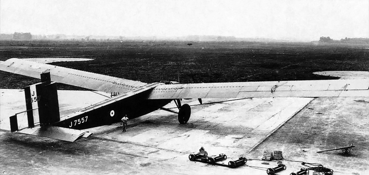
The Inflexible at Martlesham Heath. In the lower right of the image are the wheel trollies used to move the aircraft sideways into the hangar.

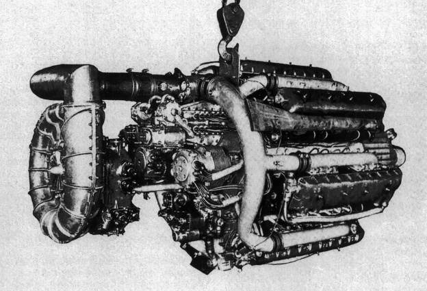
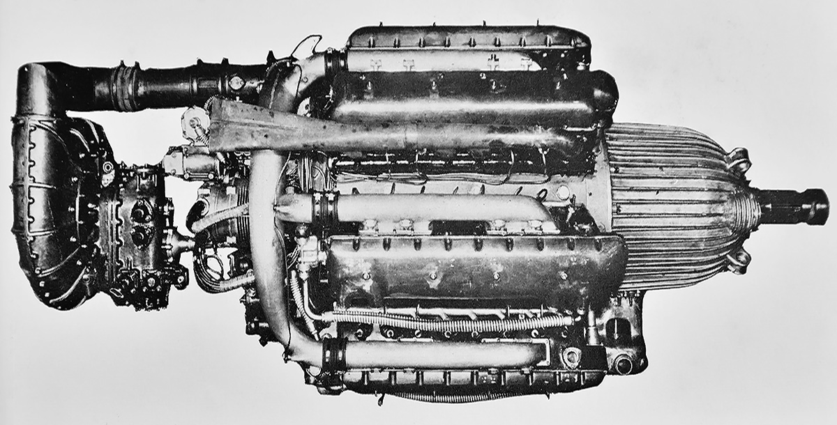
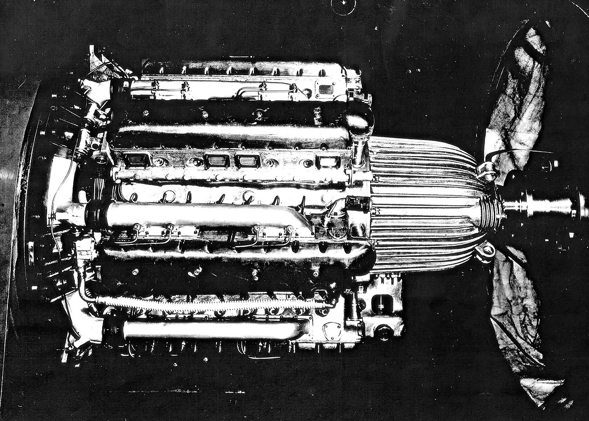
At Beardmore, the design of the Inflexible was initially laid out and modified by William. S. Shackleton. The project was later taken over by Rollo A. de Haga Haig. The aircraft’s design was tested in the Royal Aircraft Establishment’s wind tunnel at Farnborough. Except for its size, the aircraft possessed a fairly conventional layout. The monoplane trimotor had shoulder-mounted wings and taildragger landing gear. One engine was mounted in the nose, and an engine was mounted on each wing. Each engine was a water-cooled Rolls-Royce Condor II that produced 650 hp (485 kW) and turned a wooden, fixed-pitch, two-blade propeller. The radiator for the nose-mounted engine was directly below the fuselage, and the radiator for each wing-mounted engine was located under the wing between the engine nacelle and the fuselage. The two-place, side-by-side, open cockpit was positioned just forward of where the wings mounted to the fuselage. Below the cockpit on the left side of the fuselage was a small propeller for a wind-driven pump. The pump supplied oil to a servo system that boosted movement of the ailerons and elevator.

Beardmore-Inflexible-nose

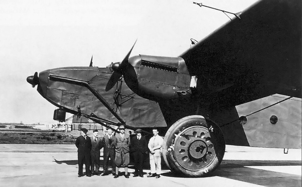
The group posing in front of the Inflexible gives scale to the aircraft’s immense size. The radiator for the fuselage-mounted engine can be seen under the nose. Exhaust manifolds carried the gasses from the center engine away from the cockpit. Just under the cockpit is the windmill for the servo system pump.

The Inflexible was made of duralumin, an aluminum alloy that incorporates copper, manganese, and magnesium for increased strength. The fuselage had a rectangular cross section and consisted of front and rear sections that were bolted together. Both sections were made of duralumin sheets riveted to a duralumin frame. Mounted to the rear of the fuselage were the horizontal and vertical stabilizers. The elevator spanned the entire length of the horizontal stabilizer. A Flettner servo tab trailed behind the rudder and controlled its movement.

The wings were formed by a wing box that bolted to the fuselage and made up the center wing section. An outer wing section bolted to each side of the wing box and was supported by two spars. Like the fuselage, the wing was covered with sheets of duralumin. A cable that kept each wing in tension while in flight connected the rear spar, at about two-thirds the span of the wing, to the lower fuselage. This cable was tensioned to about 3,000 lb (1,361 kg). The wings had a six-degree dihedral. Sections of the leading and trailing edges of the wings were hinged for access and inspection of the inner wing. The aircraft’s 656 US gal (546 Imp gal / 2,482 L) of fuel was carried in four wing tanks. The Inflexible did not have any flaps, but its large ailerons spanned the outer half of each wing’s trailing edge. Extending from each of the aircraft’s control surfaces was an aerodynamic balance horn.

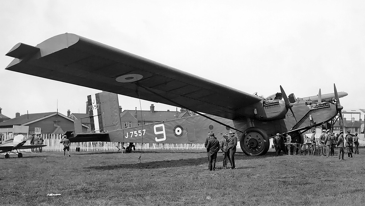
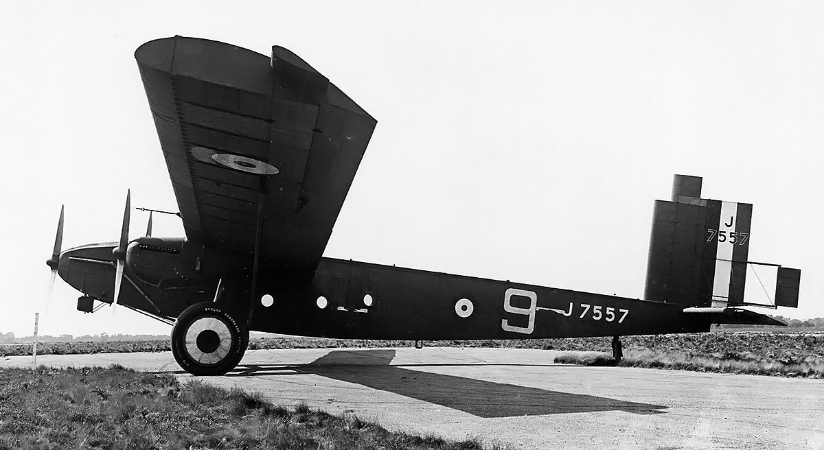
The Inflexible was on hand at the Royal Air Force Display at Hendon in late June 1928. The aircraft now has “9” painted on the fuselage. In a size comparison, the Inflexible was displayed with a de Havilland DH.71 Tiger Moth (far left). The Tiger Moth’s 22 ft 6 in (6.59 m) wingspan was about one-eighth that of the Inflexible.

The aircraft’s immense weight was supported by two large main wheels and a steerable tailwheel. During component testing, wire wheels collapsed under the expected weight of the Inflexible. New wheels were designed and made from steel and aluminum. Mounted to the wheels were 90-in (2.29-m) tall tires, specially developed by the Dunlop Rubber Company. The weight of the large tires increased by 70 lb (32 kg) when they were filled with air. Each main wheel was supported by a shock-absorbing strut that extended from just inside the engine nacelle. An A-frame mounted to the lower fuselage secured each main wheel. The main gear had a track of 25 ft 7 in (7.80 m). For landing, the main wheels had a hydraulic braking system that could be automatically applied when the tailwheel connected with the ground. This system was designed by Rohrbach engineer Kurt Tank.

The Beardmore Inflexible had a wingspan of 157 ft 6 in (48.01 m), a length of 75 ft 6 in (23.01 m), and a height of 21 ft 2 in (6.45 m). The aircraft had a top speed of 110 mph (177 km/h) at sea level and 101 mph (163 km/h) at 6,500 ft (1,981 m). Its landing speed was 65 mph (105 km/h). The Inflexible had a climb rate of 359 fpm (1.8 m/s) and took 18 minutes and 06 seconds to reach 6,500 ft (1,981 m). The aircraft’s service ceiling was 9,350 ft (2,850 m). The Inflexible had an empty weight of 24,923 lb (11,305 kg), a gross weight of 31,400 lb (14,243 kg), and a maximum weight of 37,000 lb (16,783 kg). Reportedly, the aircraft could seat 20 passengers, but it does not appear that such accommodations were ever installed.

Beardmore-Inflexible-bottom

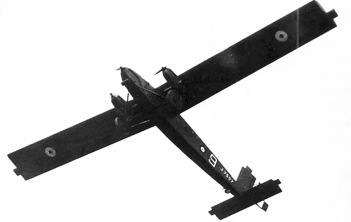
Underside of the Inflexible as it overflies the Royal Air Force Display at Hendon. The radiators for the wing-mounted engines are visible by the fuselage. Note the aerodynamic balance horns extending from all of the control surfaces.

Construction of the Inflexible progressed slowly and was often delayed by various material shortages. The aircraft was initially given civil registration G-EBNG on 29 December 1925. This registration was cancelled on 12 July 1927, and military serial number J7557 was assigned. The aircraft was completed at Dalmuir, near Glasgow, Scotland, in mid-1927. It was then broken down into various sections and transported by sea from Glasgow to Ipswich, England. However, the Aeroplane and Armament Experimental Establishment had no way to transport the large components from the Ipswich docks to the nearby Martlesham Heath Airfield. Disassembled, the two fuselage sections were 41 ft (12.50 m) long, and the outer wing sections were 61 ft (18.59 m) long. Moving the large sections of the Inflexible to Martlesham Heath required the construction of a special transport with steerable axles. Once assembled, the Inflexible’s wingspan was larger than any hanger opening at Martlesham Heath. Special trollies were built that supported each of the aircraft’s wheels and enabled movement in all directions. With the trollies, the aircraft could be moved sideways into the hanger.

Initial ground tests were started in January 1928, and the Inflexible was soon ready for flight tests when the weather was clear. The aircraft’s first flight occurred on 5 March 1928 and was flown by Jack Noakes. A Beardmore mechanic was also on the flight. The Inflexible took off in about 1,014 ft (309 m) and flew for 15 minutes; at the time, it was the world’s largest aircraft to fly. The Inflexible was stable in flight and exhibited good controls. Further flight testing revealed the aircraft to be underpowered, and its pitch and roll control was lacking in rough weather and at slow speeds. Wake turbulence from the fuselage-mounted engine also caused vibration issues with the aircraft’s tail.

Beardmore-Inflexible-flight

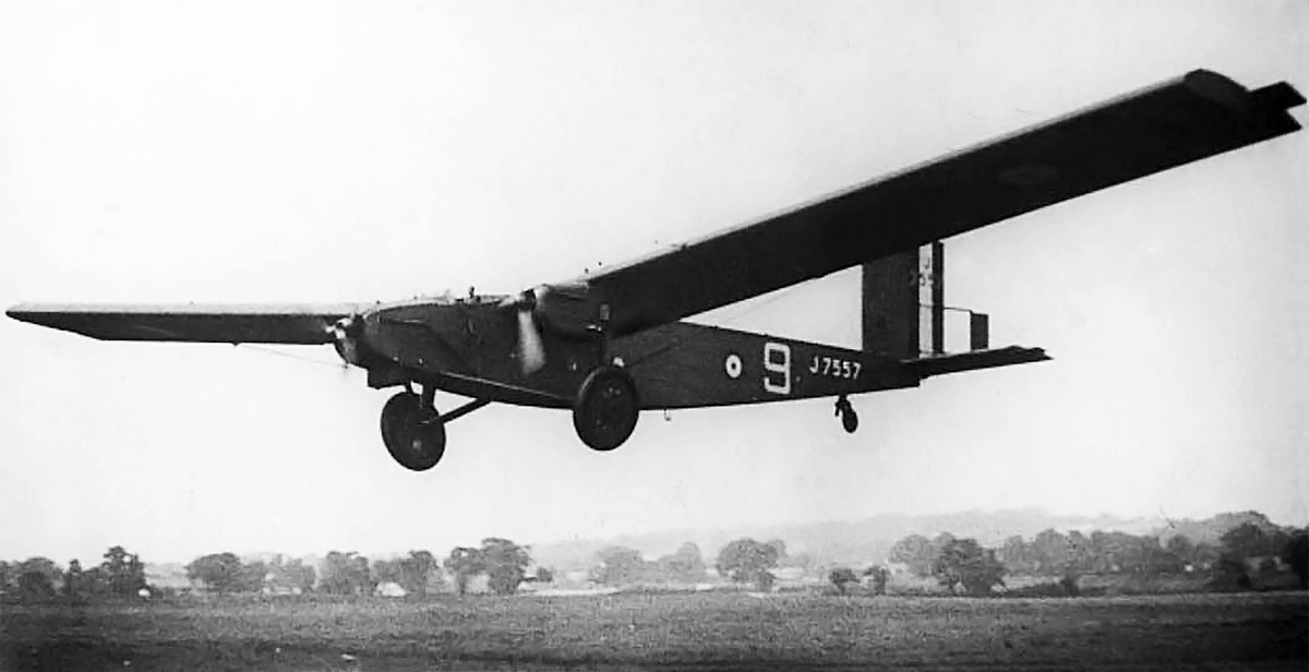
The Inflexible makes a pass during the Royal Air Force Display. The pilot, Jack Noakes, is just visible in the open cockpit.

The Inflexible was displayed for the public on at least three different occasions. On 27–30 June 1928, the aircraft was flown during the Royal Air Force Display at Hendon, near London. On 18–20 May 1929, it appeared at the Norwich Aero Club Air Display at the Mousehold Aerodrome. On 10 June 1929, the Inflexible was at the Cambridge Aero Club Display in Conington.

Beardmore struggled financially after World War I, and the aircraft department closed in February 1929. Rohrbach also suffered financial difficulties, and the company merged with a Deschimag subsidiary to form Weser Flugzeugbau GmbH in 1934. Although the Inflexible had demonstrated the feasibility of all-metal, stressed-skin construction, it would be a few years before the technique was fully adopted by the British aircraft industry. In January 1930, the Inflexible was disassembled for static tests at Martlesham Heath. The aircraft had accumulated 47 hours and 55 minutes of flight time. The engines were removed and placed into storage. After the static tests, the wings, fuselage, and other components were left exposed to the elements for corrosion tests. Occasionally, parts of the duralumin skin were removed and repurposed, and the fuselage served as a space for guards to get out of the weather. The remains of the Inflexible were eventually scrapped in 1931. The only surviving component of the aircraft is one main wheel, which is on display in the Science Museum, London.

Beardmore-Inflexible-side

Aerodynamic wheel covers were added to the aircraft sometime in early 1929. The Flettner tab controlling the rudder extended some distance behind the aircraft. The aerodynamic balance horns of the rudder and aileron are clearly visible.

Sources:
Beardmore Aviation 1913-1930 by Charles Mac Kay (2012)
British Prototype Aircraft by Ray Sturtivant (1990)
Jane’s All the World’s Aircraft 1928 by C. G. Grey and Leonard Bridgman (1928)
British Flight Testing: Martlesham Heath 1920-1939 by Tim Mason (1993)
– “Die Monster von Beardmore” by Philip Jarrett, Flugzeug Classic (May 2002)
https://earlyflightera.com/dr-adolf-rohrbach-chronicles-2/
https://en.wikipedia.org/wiki/Beardmore_Inflexible
https://en.wikipedia.org/wiki/Rohrbach_Metall-Flugzeugbau

Alfa-Romeo-1101-supercharger-rear

Alfa Romeo 1101 28-Cylinder Aircraft Engine

By William Pearce

In the early 1930s, Alfa Romeo began to build aircraft engines based on foreign designs that it licensed for production. By 1938, Alfa Romeo had obtained licenses to produce the Armstrong Siddeley Lynx, Bristol Jupiter and Pegasus, De Havilland Gypsy Major and Gypsy Six, and Walter Sagitta inverted V-12. The company had also used its knowledge and experience with licensed production to design its own engines. However, Alfa Romeo’s own D-series radial engines of the early 1930s were not successful, and its 135 engine, an 18-cylinder air-cooled radial first run in 1938, suffered from reliability issues. Giustino Cattaneo had designed the 135, but he left Alfa Romeo in 1936, before the first engine was built. Still, the design of these original Alfa Romeo engines owed much to the foreign engines built under license.

Alfa-Romeo-1101-supercharger-rear

The Alfa Romeo 1101 28-cylinder engine with its remote, two-speed supercharger. Note the induction system from the supercharger to the cylinders. The fuel injection pump and magnetos can be seen on the back of the engine. One cylinder bank has a seemingly restrictive exhaust manifold attached.

In 1938, Ugo Gobbato, Managing Director of Alfa Romeo, tasked the Special Studies Service (Servizio Studi Speciali / SSS) to design an entirely new aircraft engine. The SSS was Alfa Romeo’s secret or special projects department. Wifredo Ricart, a Spaniard who escaped his country’s civil war and fled to Italy in 1936, was in charge of the new engine’s design, which was designated 281.

The 281 was an inline radial that consisted of seven cylinder banks, each with four cylinders. The liquid-cooled engine was equipped with a single-speed, single-stage centrifugal supercharger. The 281 engine had a 4.72 in (120 mm) bore, a 4.33 in (110 mm) stroke, and displaced 2,126 cu in (34.83 L). With the bore larger than the stroke, the oversquare engine was designed have a relatively small diameter and operate at higher rpm. The engine had an estimated output of 1,480 hp (1,089 kW) at 3,000 rpm. The 281 was designed with then-current power requirements in mind, but did not consider future demands for power increases. The 281 design produced basically the same power as the 135, although it was 35 in (.88 m) in diameter compared to 55 in (1.40 m) for the 135. Realizing that a more powerful engine was needed, Ettore Pagani, also of the SSS, completed a design study in 1939 of an enlarged 281 to produce an excess of 2,000 hp (1,471 kW). This engine became known as the 1101. The 281 was never built.

The Alfa Romeo 1101 was initially designated 101, but it was also referred to as the 1.101 and 1.1.01. However, 1101 has become the most common designation. The design team for the 1101 consisted of Ricart, Orazio Satta, and Giuseppe Busso. The engine had a cast aluminum crankcase with seven cylinder banks mounted radially around its center and spaced at 51.4 degrees. The upper cylinder bank extended vertically from the crankcase. Each cylinder bank contained four cylinders and was made from cast aluminum with an integral cylinder head. Wet cylinder liners made of nitrided steel were installed in the cylinder block. Each cylinder had one intake valve and one sodium-cooled exhaust valve. The intake valve was 2.56 in (65 mm) in diameter, and the exhaust valve was 2.20 in (56 mm) in diameter. The valves for each cylinder bank were actuated via hydraulic tappets by a single overhead camshaft. The camshaft was driven by bevel gears and a vertical shaft from the front of the engine. The one-piece crankshaft was supported by five main bearings. The pistons for each row of cylinders were served by a master connecting rod with six articulated connecting rods. The cylinders had a compression ratio of 6.5 to 1.

Alfa-Romeo-1101-front

Front view of the 1101 illustrates the vertical drives for the camshafts. The four mounts on the front of the gear reduction are visible. A sump is positioned between the two lower cylinder banks.

Mounted to the front of the engine was a propeller gear reduction. Via planetary bevel gears, the propeller shaft rotated at .400 times crankshaft speed. Mounted to the rear of the engine were two fuel injection pumps and two magnetos. The primary injection pump had a maximum flow of 423 gallons (1,600 L) per hour and delivered fuel to the injectors mounted in the intake side of the cylinder head. The secondary fuel injection pump had a maximum flow of 132 gallons (500 L) per hour and delivered methanol (methyl alcohol) to injectors located in the intake manifold just before the intake port of each cylinder. The methanol was used to increase maximum power and reduce detonation. Each of the two magnetos fired one of the two spark plugs mounted in each cylinder.

A shaft extending from the rear of the engine powered a remote, two-speed, centrifugal supercharger. The 1101 engine as built did not have a supercharger mounted in a housing that attached directly to the rear of the crankcase. Some sources indicate that the engine had a two-stage supercharger, but photos show just the remote supercharger with no other stage apparent. Two-stage supercharging was certainly planned for future versions of the 1101 engine. Air entered the back of the supercharger, where it was compressed to provide 11.4 psi (.78 bar) of boost. A duct extending from the supercharger was intended to incorporate an aftercooler, but surviving photos do not show one installed. From the duct, the air entered a semi-annular manifold located at the rear of the engine. Seven individual runners extended from the semi-annular manifold and connected to each cylinder bank. The runners had four outlets grouped in two pairs of two and mounted to the left side of the cylinder bank. Each cylinder bank had four exhaust ports on its right side, and the exhaust ports for the middle two cylinders of each bank were grouped together.

A centrifugal water pump, most likely mounted to the lower rear of the engine, flowed coolant at 14,530 gallons (55,000 L) per hour. The coolant was a mix of 70 percent water and 30 percent ethylene glycol. Double dynafocal engine mounts were located on the back side of each cylinder bank. The propeller gear reduction housing also had four mounts.

The engine was officially designated Alfa Romeo 1101 RC37/87. The “RC” stood for Riduttore de giri (gear reduction) and Compressore (supercharged), and 37/87 designated the critical altitudes (in hectometers) at which maximum continuous power was obtained with its two-speed supercharger. The engine had a 5.31 in (135 mm) bore and a 4.92 in (125 mm) stroke. This gave the 1101 a displacement of 3,057 cu in (50.10 L). However, since the strokes of the articulated rods were slightly longer than that of the master rod, the engine had an actual displacement of 3,066 cu in (50.25 L). Takeoff power was 2,200 hp (1,618 kW) at 2,625 rpm. For one minute at emergency power and 2,800 rpm, the engine produced 2,300 hp (1,692 kW) at 7,546 ft (2,300 m) in low gear and 2,150 hp (1,581 kW) at 26,247 ft (8,000 m) in high gear. For five minutes at military power and 2,700 rpm, the engine produced 2,000 hp (1,471 kW) at 10,827 ft (3,300 m) in low gear and 1,900 hp (1,398 kW) at 28,215 ft (8,600 m) in high gear. Maximum continuous power was achieved at 2,625 rpm, with the engine producing 1,850 hp (1,361 kW) at 12,139 ft (3,700 m) in low gear and 1,750 hp (1,287 kW) at 28,543 ft (8,700 m) in high gear. The 1101 had a diameter of 44.7 in (1.14 m) and was 97.2 in (2.47 m) long. The engine weighed 2,535 lb (1,150 kg) without accessories.

Alfa-Romeo-1101-supercharger-side

The 1101’s aftercooler was to be incorporated into the induction pipe between the supercharger and the ring manifold. Note the shaft housing extending back from the engine to power the supercharger.

The 1101 was designed and built at Alfa Romeo’s plant in Pomigliano d’Arco, near Naples, Italy. As the 1101 was being built, Italy had secured licenses from Germany to build the Daimler-Benz DB 601 and DB 605 engines and tasked Alfa Romeo with their production. This led to the formation in 1941 of Alfa Romeo Avio, a division focused solely on producing aircraft engines. The 1101 engine was completed in late December 1941 and first run in early January 1942. Under tests, the 1101 experienced detonation issues that damaged the pistons and cylinder heads. These issues were caused by the 87 octane fuel and the timing of the fuel injection system.

Development of the engine progressed until early 1943, when the war situation required the dispersal of factories away from populated areas. The 1101 engine project was moved to Armeno in northern Italy, near the Swiss border. The move caused delays, but the entire project was suspended on 8 September 1943, following news of the Italian armistice. The Armeno plant housing the 1101 fell in the territory controlled by the newly formed Italian Social Republic (Repubblica Sociale Italiana), which was mostly controlled by Germany. It is not clear if work on the 1101 engine was resumed or stayed suspended, but by mid-1943, the Armeno plant housed nearly all of the engine’s documentation, the prototype engines, and parts for approximately 20 pre-production examples. On 18 June 1944, all of the materiel in the Armento plant was destroyed by Italian partisans (resistance fighters) to prevent its use by the German military.

Future development of the 1101 included two-stage supercharging to increase the engine’s military power rating to 2,300 hp (1,692 kW). Most likely, this configuration would include an additional centrifugal supercharger incorporated in a housing mounted directly to the rear of the crankcase and mechanically driven from the crankshaft. Investigations were also conducted into turbocompounding the engine. The turbocompounded 1101 would utilize five turbines. Three turbines would be positioned at the front of the engine to recover power from the exhaust and feed it back to the propeller shaft. The remaining two turbines were turbosuperchargers (first stage of supercharging) positioned at the rear of the engine to feed air into the engine’s centrifugal supercharger (second stage of supercharging). The turbocompounded engine was expected to weight 20 percent more, increase fuel efficiency by 15 percent, and produce 2,600 (1,912 kW) hp. However, no such engines were built.

Alfa-Romeo-1101-test-side

The 1101 mounted on what appears to be a test bed. This image gives a good view to the spacing of the intake and exhaust ports. Note the two dynafocal mounts on the back of each cylinder bank. It is not clear if the remote supercharger has been omitted or is just obscured by the mounting frame.

Other developments included enlarging the engine’s cylinder, possibly with a 5.71 in (145 mm) bore and a 5.12 in (130 mm) stroke, so that total displacement was 3,668 cu in (60.1 L). Studies were also undertaken to create a 42-cylinder engine by having six cylinders per bank. Some sources indicate that this engine had a displacement of approximately 4,270 cu in (70 L). However, the bore and stroke of the 1101 would displace 4,586 cu in (75.1 L) with 42 cylinders. Therefore, the bore and stroke of the 4,270 cu in (70 L) 42-cylinder engine are not known.

The 1101 was proposed for at least three aircraft projects: the Alfa Romeo 1902—apparently a development of the Aeronautica Umbra MB-902 design, with the two engines buried in the fuselage and driving propellers on each wing via extension shafts and right-angle drives; the Caproni Vizzola MCT (Monoposto Caccia Trigona / Tr.1207)—a single seat fighter of a taildragger configuration with the engine buried in the fuselage behind the cockpit and driving a tractor propeller via an extension shaft; and the Savoia-Marchetti SM-96 (II)—a single seat taildragger fighter of a conventional tractor layout with the engine installed in the nose. None of these projects were built.

Two Alfa Romeo marine engines utilized 1101 components: the inline, four-cylinder 1001 engine used a single cylinder bank, and the V-8 1002 engine used two cylinder banks. Both of these engines were built during World War II and neither appear to have entered quantity production. The only known part of an 1101 engine to survive is a fuel injection pump stored at the Alfa Romeo Museum (Museo Storico Alfa Romeo) in Arese, Italy.

Note: The horsepower (hp) figures in this article are actually Cavalli Vapore (CV), which is 1.387% more than a standard hp (100 CV = 98.6 hp). The kilowatt (kW) values are based on CV.

Caproni-Vizzola-MCT-Alfa-Romeo-1101

A composite drawing of the Caproni Vizzola MCT (Monoposto Caccia Trigona / single seat fighter, designed by Emmanuele Trigona) with the 1101 engine installed in the fuselage.

Sources:
– “Destini incrociati” by Luigi Montanari, epocAuto Anno 14, N.1 (January 2019)
– “Le attività aeronautiche in Alfa Romeo fino al 1945” by Fabio Morlacchi, L’Alfa Romeo di Ugo Gobbato 1933-1945, Monografi AISA 92 (2 April 2011)
https://it.wikipedia.org/wiki/Alfa_Romeo_1101
https://www.secretprojects.co.uk/threads/alfa-1101.5117/
https://www.secretprojects.co.uk/threads/savoia-marchetti-sm-96-ii.7636/