Sunbeam Sikh I

Sunbeam Sikh I, II, and III Aircraft Engines

By William Pearce

Toward the end of World War I, a number of companies were pursuing the concept of a very large engine powering a very large aircraft. Just about every country that had extensive experience in the field of aeronautics expended resources to create the large engine and aircraft combination. As history unfolded, all of these projects came to naught, although the experience gained did pave the way for future projects.

Sunbeam Sikh I

Side view of the 800 hp (597 kW) Sunbeam Sikh I V-12 engine. Carburetors can be seen attached to the first and last cylinders. Note the two water pumps under the engine and the exposed valves.

The Sunbeam Motor Car Company based in Wolverhampton, England had added aircraft engine design and manufacture to its existing automotive business in 1913. Sunbeam’s aircraft engines were designed by Louis Coatalen, their chief engineer, and were sometimes referred to as Sunbeam-Coatalen Aircraft Engines. As with so many other companies, Sunbeam designed a large aircraft engine during the closing days of World War I. This large engine was named Sikh (or Sikh I), and it was intended for use in either large aircraft or airships.

The Sikh was a 60 degree V-12 engine. Its individual cylinders were a departure from the standard Coatalen-designed engines. The cylinders were machined from steel forgings and had welded sheet metal water jackets. Each cylinder had four spark plugs positioned under its six exposed valves. The three intake valves were positioned on the Vee side of the cylinder, and the three exhaust valves were positioned on the outside of the cylinder. The intake and exhaust valves were operated by separate rocker groups positioned above the valves. This configuration allowed all intake (or exhaust) valves to be opened or closed simultaneously. Each rocker group was actuated by a pushrod that was driven by a camshaft mounted in the Vee of the engine and geared to the crankshaft. Four magnetos at the rear of the engine fired the spark plugs.

Sunbeam Sikh I Ad copy

A Sunbeam Sikh ad from 1920 touts the engine as the most powerful in the world but prophetically adds, “at the moment.” The Duesenberg H developed at the same time as the Sikh I had the same output, and the 1,000 hp (746 kW) Napier Cub would eclipse both engines later in 1920.

Two water pumps were positioned under the engine and driven by vertical shafts from an accessory gear. Each pump supplied cooling water to one cylinder bank. The Sikh had four carburetors—one attached to the first and last cylinders of each row. For each cylinder row, the air/fuel mixture flowed through an intake manifold attached to the cylinders inside the Vee of the engine. The engine used aluminum pistons mounted to H section, forked connecting rods attached to the crankshaft. The hollow crankshaft was made of nickel-chromium steel. Via spur reduction gears, the propeller shaft turned at 0.657 engine speed. The crankcase of the Sikh was an aluminum casting.

The Sunbeam Sikh had a 7.09 in (180 mm) bore and 8.27 in (210 mm) stroke. The engine’s total displacement was 3,913 cu in (64.1 L), and it produced 800 hp (597 kW) at 1,400 rpm. The Sikh had a dry weight of 1,952 lb (885 kg).

The engine was first run on 11 May 1919 and was displayed at a number of aviation shows. Although the Sikh passed British Air Ministry tests to prove its airworthiness, Sunbeam did not receive any orders for the engine. Large engines and large aircraft were simply not practical in the early 1920s, and there was little interest in airships in the immediate post-war era.

In addition to the Sikh, Sunbeam co-developed a smaller engine known as the Sikh II (or Semi-Sikh). The inline-six Sikh II was essentially half a Sikh. The cylinders were the same but they were mounted on a new crankcase. The Sikh II was direct drive without any gear reduction, and the camshaft was mounted on the left side of the engine. With the same bore and stroke as the Sikh, the Sikh II had a total displacement of 1,956 cu in (32.1 L) and produced 425 hp (317 kW) at 1,400 rpm. The engine had a dry weight of 1,120 lb (508 kg). Unfortunately for Sunbeam, the Sikh II, like the Sikh, found no applications.

Sunbeam Sikh I Olympia 1920

The Sunbeam Sikh I as displayed at the Olympia Air Show in 1920. Note the two spark plugs positioned under the valves on both sides of the cylinder, the pushrods in the Vee of the engine, and the four magnetos. In the left corner of the picture is the Short Silver Streak. (Stilltime Collection Image)

By 1927, British airship development had been renewed, and the R100 and R101 programs were underway. Sunbeam saw a new opportunity for the Sikh engine and developed the Sikh III strictly for airship use. The Sikh III was again a 60 degree V-12 engine, and most sources say it possessed the same bore, stroke, and displacement as the original Sikh. However, some original sources (Jane’s and Flight) say the bore was increased to 7.28 in (185 mm), which would give a total displacement of 4,134 cu in (67.7 L).

The individual cylinders of the Sikh III were redesigned and refined using a carbon steel barrel and a cast steel head. In addition, the valve train was completely redesigned. Each cylinder still had three exhaust valves, but the number of intake valves was reduced to two. The valves for each cylinder were enclosed in a common rocker cover. The rockers extended though the cover and were actuated by pushrods that ran between the cylinders. On the left cylinder bank, the exhaust rocker arm protruded out the rear of the cover, and the intake rocker arm protruded out the front. This configuration was reversed for the right cylinder bank. The crankshaft was forged from nickel-chromium steel and had six throws. Each cylinder had two spark plugs that were enclosed by the rocker cover. The spark plugs were fired by two magnetos driven at the rear of the engine.

Sunbeam Sikh II

The inline-six Sunbeam Sikh II was essentially half a Sikh I. Note the camshaft and pushrod arrangement in the rear view on the left. The front view image on the right illustrates the engine’s carburetors, valves, and lack of a propeller gear reduction.

The engine used two carburetors, which, along with the intake manifolds, were positioned in the Vee of the engine. Each carburetor supplied the air/fuel mixture to three cylinders of each bank. The propeller shaft of the Sikh III was geared to the crankshaft at a 0.567 reduction. The Sikh III produced 1,000 hp (476 kW) at 1,650 rpm and had a dry weight of 2,760 lb (1,252 kg). The engine was 7 ft 2 in (2.2 m) long, 3 ft 4 in (1.0 m) wide, and 6 ft 2 in (1.9 m) tall.

The Sikh III was first run in 1928 and was displayed at shows in 1929 and 1930. However, engines for the R100 and R101 airships had already been selected. The disastrous crash of the R101 airship in 1930 caused Britain to cease all further airship development, leaving the Sikh III without any possible applications.

Only small numbers of Sikh I, Sikh II, and Sikh III engines were built. Like many large aircraft engines built over the years, the Sunbeam Sikh engines were never installed in any aircraft or airships.

Sunbeam Sikh III

The Sunbeam Sikh III was intended for airship use but never found an application. Note the new cylinder heads. The exhaust valve pushrod can been seen on the rear left cylinder.

Sources:
Sunbeam Aero-Engines by Alec Brew (1998)
Aerosphere 1939 by Glenn D. Angle (1940)
Jane’s All the World’s Aircraft 1927 by C. G. Grey
Jane’s All the World’s Aircraft 1929 by C. G. Grey
– “The Sunbeam Motor Car Co., Ltd.” The Aeroplane (31 December 1919)
– “Aero Engines at Olympia” The Aeroplane (21 July 1920)
– “The Sunbeam Motor Car Co., Ltd.” Flight (18 July 1929)

Dorand Gyroplane G20 complete 1947

Dorand Gyroplane G.20 (G.II)

By William Pearce

Since the early 1900s, Frenchman Louis Bréguet was interested in rotorcraft. But, the technical challenges of controlling such machines and the lack of suitable power plants led Bréguet to pursue the development of aircraft instead. In the late 1920s, Bréguet’s interest returned to rotorcraft, and he created the Syndicat d’Etudes de Gyroplane (Syndicate for Gyroplane Studies) in 1931 with René Dorand as its Technical Director. The syndicate produced a successful experimental helicopter known as the Bréguet-Dorand Gyroplane Laboratoire, which first flew on 26 June 1935. The Gyroplane Laboratoire used two sets of two-blade, coaxial, contra-rotating rotors. No tail rotor was used, as the contra-rotating rotors cancelled out the torque reaction of the blades. The helicopter set a number of speed and distance records.

Dorand Gyroplane G20

A drawing of the Dorand Gyroplane G.20 in what appears to be its final form. The drawing illustrates one of the two inverted Renault inline-six engines and the two-person cockpit.

In 1938, Dorand amicably parted with Bréguet and established the Société Française du Gyroplane (French Gyroplane Company), abbreviated SFG or just Gyroplane for short. The French Navy (Marine Nationale) commissioned the SFG to design a combat helicopter for costal defense and anti-submarine warfare. Dorand designed the new machine, and its layout was similar to that of the Gyroplane Laboratoire. The new helicopter was designated the Gyroplane G.20, but it is also known as the Dorand G.20 or the Dorand G.II.

The G.20 had a cigar-shaped fuselage of all metal construction. A butterfly tail was attached to the extreme end of the fuselage, and the tail’s control surfaces were fabric-covered. The streamlined nose of the G.20 was covered with plexiglass panels. The pilot sat in the nose of the helicopter with either one or two crewmen behind.

Dorand Gyroplane G20 org drawing

A drawing of the original Dorand G.20 with its three-man crew and rotor mast gunner turret. Note the side-mounted machine gun (pointed toward the rear) and the bomb load. An inverted, inline, six-cylinder, Renault engine is also visible. The rotors on the left are shown in their normal position, while the rotors on the right are at their maximum upward deflection.

At the center of the helicopter were two three-blade, coaxial, contra-rotating rotors. The distance between the rotors was 2 ft 2 in (0.65 m), and the lower rotor had a smaller diameter than the top rotor to ensure the blades would not collide. The upper rotor had a diameter of 50 ft 6 in (15.4 m), and the lower rotor’s diameter was 42 ft 8 in (13.0 m)—7 ft 10 in (2.4 m) smaller.  The magnesium blades were made of two parts: a box forming the leading edge and a separate trailing edge. As with the Gyroplane Laboratoire, articulation of the blades allowed for both cyclic and collective pitch control, and no tail rotor was used.

The rotor blades were powered by two Renault 6Q-04 engines. The 6Q was an air-cooled, inverted, inline, six-cylinder engine with a 4.72 in (120 mm) bore and a 5.51 in (140 mm) stroke. The engine’s total displacement was 580 cu in (9.5 L). The 6Q-04 was supercharged and produced 240 hp (179 kW) at 2,500 rpm up to 13,123 ft (4,000 m). A special gearbox transferred power from the engines to the rotors. If one of the engines were to fail, that engine would be automatically disconnected, and the remaining engine would power both sets of rotors.

Dorand Gyroplane G20 org drw

This top view drawing of the G.20 clearly shows the side-mounted machine gun and engine placement. The outline of bombs can be seen under the rotor mast.

The G.20 was supported by two main wheels and a tailwheel. The tail and main wheels all retracted backward into the fuselage and were fully enclosed by gear doors. The space in the fuselage between the main gear and below the rotors was for either bombs or a depth charge. In addition, Dorand’s original design included a machine gun mounted on the helicopter’s side and a turret mounted on top of the rotor mast—with the guns operated by separate crewmen. The mast turret was unique in that it was essentially a hollow drum to which the rotors were attached. A gunner occupied the center of the drum and had a 360 degree field of fire. However, all armament and the rotor turret were omitted from the G.20. Most sources list the completed G.20 as having a two-person crew consisting of a pilot and copilot. The helicopter’s final role was defined as observation, liaison, and mail-carrying.

The G.20’s fuselage had a length of 36 ft 4 in (11.08 m) and a height of 10 ft 3 in (3.13 m). The helicopter’s empty weight was 3,086 lb (1,400 kg); normal operating weight was 5,512 lb (2,500 kg), and maximum weight was 6,614 lb (3,000 kg). The G.20’s hover ceiling was 9,843 ft (3,000 m), and it had a maximum ceiling of 16,404 ft (5,000 m). The helicopter’s range was 497 mi (800 km). Its cruise speed was 103 mph (165 km/h), and its maximum speed was 155 mph (250 km/h) at 8,202 ft (2,500 m).

Dorand Gyroplane G20 complete 1947

The completed Dorand G.20 after World War II. With the machine guns no longer part of the design, nothing is left to interrupt the helicopter’s sleek lines. Note the long gear door.

Construction of the G.20 started in Guethary in south-western France, near Spain. When the German Army invaded France in 1940, the helicopter was moved to Chambéry in south-eastern France, near Italy, and construction resumed. By this time, Marcel Vuillerme had taken over the project from Dorand. As the Germans pushed into southern France, the G.20 was discovered. The Germans showed little interest in the helicopter and allowed its construction to continue, albeit slowly.

The G.20 was completed in 1947 and underwent ground tests. It was the French officials who now showed little interest in the project, and funding was not forthcoming. Its estimated performance was optimistic, and while its streamlined appearance and retractable gear appeared futuristic, in many ways the G.20 was obsolete after war-time helicopter developments made in the United States and Germany. Further development and testing of the G.20 was abandoned, and the helicopter never flew. However, the SFG continued to develop helicopters for a time. The SFG worked with Bréguet to construct a four-passenger helicopter, the G.11E, which first flew in 1949. The G.111 was a follow-on project that first flew in 1951. The SFG went out of business in 1952.

Breguet G11E

The G.11E was designed by SFG after the G.20. It was built by Bréguet and powered by a 9-cylinder Potez 9E radial engine. It first flew in 1949 and had a layout similar to the G.20.

Sources:
Les Avions Breguet 1940/1971 by Jean Cuny and Pierre Leyvastre (1973)
René Dorand: 50 Ans de Giraviation by Pierre Boyer (1992)
http://en.wikipedia.org/wiki/Breguet-Dorand_Gyroplane_Laboratoire
http://en.wikipedia.org/wiki/Breguet_G.11E

Napier-Heston Racer front 3-4 2

Napier-Heston Racer

By William Pearce

Near the end of World War I, D. Napier & Son built one of the most outstanding aircraft engines of all time: the 12-cylinder Lion. Lion production continued through the 1920s and 1930s, and other Napier aircraft engines did not achieve a level of success anywhere near that of the Lion. In the 1930s, Major Frank Halford was the head aircraft engine designer at Napier and was working on H-type engines. Compared to contemporary aircraft engines, Halford’s new engines used a smaller cylinder bore and stroke and ran at a higher rpm. In the late 1930s, Halford’s latest engine was the Sabre—a sleeve valve engine with 24 cylinders of 5.0 in (127 mm) bore and 4.75 in (121 mm) stroke. The Sabre displaced 2,238 (36.7 L) and was capable of over 2,000 hp (1,491 kW) and speeds up to 4,000 rpm.

Napier-Heston Racer front 3-4

The Napier-Heston Racer’s sleek lines and wide-track undercarriage are apparent in this view of the aircraft taken at the Heston Airport.

Napier wanted a way to demonstrate their new aircraft engine to the world. In its earlier days, the Lion had powered aircraft used to set world speed records. Since 1937, the Germans had held the landplane 3 km (1.86 mi) world speed record at 379.38 mph (610.55 km/h), and since 1934, the Italians had held the absolute 3 km (1.86 mi) world speed record at 440.682 mph (709.209 km/h). Napier felt a specially designed aircraft powered by a Sabre engine would be capable of setting a new speed record at over 480 mph (772 km/h), beating both the Germans and Italians. Not only would this achievement be great marketing, it would also bring the record back to Britain and embarrass Hitler’s Germany and Mussolini’s Italy.

Under lead designer Arthur E. Hagg, Napier laid out its racer design in mid-1938. Hagg previously designed the de Havilland DH.91 Albatross transport, and the two aircraft share some family resemblance. The racer’s sole purpose was to break the 3 km (1.86 mi) world speed record, and it was not intended as a testbed for the Sabre engine. The British Air Ministry was unwilling to financially support the project, but Lord Nuffield (William Richard Morris) stepped forward to independently fund the construction of two aircraft. In addition, a number of vendors donated parts and services or offered them at cost. Since Napier did not have the resources to construct the racer, the Heston Aircraft Company was selected to build the aircraft in late 1938. The Heston team was led by George Cornwall. The association between Napier and Heston gave the aircraft its popular name: the Napier-Heston Racer. The aircraft is also known as the Nuffield-Napier-Heston Racer, the Heston J.5 High-Speed Aircraft, and the Heston Type 5 Racer.

Napier-Heston Racer rear 3-4

The Napier-Heston Racer was painted silver with dark blue registration letters. Many layers of aircraft dope were applied to the birch ply sheeting that made up the exterior of the aircraft; this created a surface free from even the most minor of imperfections.

To expedite construction, the Napier-Heston Racer was built almost entirely of wood. The wing spars were made from compregnated wood of multiple laminations bonded with resin under high pressure. The fuselage frame and stringers and wing ribs were made of spruce. The wings and fuselage were covered with birch ply sheets. Split flaps were incorporated into the wings. The control surfaces had aluminum alloy frames and were covered with fabric. A variable-ratio control system was designed for the elevator. This system kept the elevator movements small when the control stick was near the neutral position. As the control stick was moved farther from neutral, the relative elevator movement became greater. This system was employed so that very precise elevator movements could be achieved at high speeds.

The Napier-Heston Racer was fitted with one of the first six Sabre I prototype engines, but its boost was increased. The standard Sabre I engine produced 2,000 hp at 3,700 rpm, but the racer’s engine produced 2,450 hp (1,827 kW) at 3,800 rpm. The racer had a 10 ft 9 in (3.28 m) diameter, metal, three-blade, de Havilland constant-speed propeller. Wing root intakes led to the engine’s supercharger. A radiator was housed in a duct under the aircraft. The radiator’s upper and lower surfaces were sloped back and formed a deep V in the duct. After air passed through the radiator, it was expelled under the horizontal stabilizer on both sides of the tail. A channel above the radiator skimmed off the turbulent boundary layer, allowing it to bypass the radiator. The wide-track (14.8 ft / 4.5 m) main gear retracted fully into the wings, and a small tail skid was incorporated into the fixed fin of the tail. After many layers of aircraft dope were applied, the fit and finish of the racer was near perfection.

Napier-Heston Racer left

The rather small size of the Napier-Heston Racer is illustrated in this photo. The radiator’s intake duct can be seen under the aircraft, and its exit duct under the horizontal stabilizer. Note the bulges in the cowling to allow clearance for the Sabre’s cylinder banks.

Between the engine and fully enclosed cockpit was a 73 gallon (276 L) fuel tank. At full throttle, the aircraft’s endurance was only 18 minutes. The racer had a wingspan of 32 ft (9.75 m), a length of 24 ft 7 in (7.50 m), and a height of 11 ft 10 in (3.61 m). Its fully loaded weight was 7,200 lb (3,267 kg). All tolerances were kept to a minimum, and the racer was highly polished to remove any imperfections. The aluminum engine cowling had four bulges to allow clearance for the Sabre’s cylinder banks. The cowling sealed so tightly that small air vents were installed on the bulges to ensure that no combustible vapors built up in the engine compartment.

The first flight of a Sabre engine occurred on 31 May 1939. The engine was installed in a Fairey Battle flown by Chris Staniland. The Sabre-powered Battle had accumulated a number of hours before the special engine in the Napier-Heston Racer was first run on 6 December 1939. The racer was painted silver, with the registration of G-AFOK painted in dark blue. Taxi tests began on 12 March 1940 at Heston Airport. The engine and taxi test did not reveal any issues with control or engine cooling.

The Napier-Heston Racer’s first flight was delayed by weather but finally occurred on 12 June 1940. Squadron Leader G. L. G. Richmond was at the controls and flew the aircraft off from the 3,900 ft (1,189 m) grass field at Heston Airport. Reportedly, Richmond chose to make this flight without the canopy in place. Shortly after liftoff, the Sabre engine rapidly overheated, and Richmond tried to quickly bring the plane in for a landing. Sources disagree on exactly what happened next.

Napier-Heston Racer front

Two of the small engine compartment vents can just be seen on the upper bulges of the cowling. The exterior of the aircraft was kept as aerodynamically clean as possible.

Some sources state that Richmond was preoccupied with the emergency and was also being scalded by the overheated cooling system. They claim that he may have experienced some difficulty mastering control of the variable-ratio elevator, as he had almost touched down after a steep approach when the aircraft rose sharply back into the air and stalled. Other sources point out that the racer did not exhibit any cooling issues during the numerous ground engine runs and that Richmond was scalded when the coolant pipes burst as a result of the hard landing after the stall. They contend that the aircraft’s elevator became ineffective as a result of low speed and that it was possibly in the wings’ turbulent airflow during the steep pitch up before the stall. While some sources state the Sabre engine seized, others report the ignition was on and the engine was running but that Richmond did not advance the throttle because of its overheated state.

Richmond’s flight in the Napier-Heston Racer was only about six minutes, and he never retracted the gear. After liftoff, he immediately brought the aircraft around for landing. Richmond’s actions indicate he felt something was wrong very early on. While a burst cooling pipe would explain the cooling issues and Richmond’s scalding, and control issues with the elevator would explain the odd altitude deviations in the aircraft’s final moments, the exact issues and sequence of events may never be known.

Napier-Heston Racer front 3-4 2

The wing root intake scoops that provide air to the Sabre engine can clearly be seen in this photo. Two three-into-one exhaust manifolds on each side of the racer collected the Sabre’s exhaust gases.

The end result was that the Napier-Heston Racer stalled about 30 ft (9 m) above the grass runway and hit the ground hard. The impact broke the landing gear, the left wing, and the rear fuselage just behind the cockpit. Fortunately, Richmond was able to walk away from the wreck. With the war against Germany underway, no attempt was made to repair the Napier-Heston Racer. The racer’s Sabre engine was not badly damaged. It was rebuilt and installed in a production Hawker Typhoon that was used during the war. Although the second racer, registered as G-AFOL, was around 60% complete, it was never finished. The Napier-Heston Racer project had cost Lord Nuffield £50,000 to £100,000.

Between the time the Napier-Heston Racer was conceived and its first flight, Germany had increased the absolute world speed record to 469.221 mph (755.138 km/h). However, the Chief Technician and Aerodynamicist at Heston Aircraft, R. A. Clare, had estimated that the Napier-Heston Racer could achieve a maximum of 508 mph (818 km/h) over the 3 km (1.86 mi) course. While the true capabilities of the racer will never be known, attempts have been made to create a flying replica. Due to the high cost of such a project and the extreme rarity of Sabre engines, for now, a Napier-Heston Racer replica remains just a dream.

Napier-Heston Racer right side

The Napier-Heston Racer ready to fly at the Heston Airport. It is unfortunate that the aircraft never had a chance to demonstrate its true potential.

Sources:
– “The Napier-Heston Racer” by Bill Gunston Aeroplane Monthly (June 1976)
– “Napier-Heston Racer postscript” Aeroplane Monthly (August 1976)
– “A Co-operative Challenger” Flight (15 April 1943)
– “The Heston Napier Monoplane” by H. J. Cooper The Aero Modeller (August 1943)
By Precision Into Power by Alan Vessey (2007)

Curtiss XF6C-6 Page Navy Racer 18-08-1930

Curtiss XF6C-6 Page Navy Racer

By William Pearce

After World War I, it was clear that aircraft were vehicles with great potential, and not just playthings for the rich or eccentric. A rivalry built up between the United States Marine Corps, Navy, Army, and civilians as they each explored aviation in the 1920s. The military branches competed with each other in various races, with floatplanes switching to wheels for land-based races and wheeled aircraft switching to floats for sea-based races.

Curtiss XF6C-6 Page Navy Racer

The Curtiss XF6C-6 Page Navy Racer created for the 1930 Thompson Trophy Race.

US Marine Corps Captain Arthur H. Page flew his float-equipped Curtiss F6C-3 racer to victory in the Curtiss Marine Trophy Race on 31 May 1930, besting the rest of the field, which consisted entirely of Navy pilots. The F6C-3 was a member of the Curtiss Hawk family of biplane fighter aircraft, which had been steadily developed since the first Hawk was built for the Army in 1923. The F6C-3 had a fuselage and tail made of welded steel tubing and covered with fabric. The wings had a spruce structure and were fabric covered. Page’s F6C-3 (serial A-7147) had been cleaned up aerodynamically to achieve every bit of speed possible, and it averaged a race-record 164.08 mph (264.06 km/h).

Page knew he would need more speed from the F6C-3 if he were to have any chance in the inaugural Thompson Trophy Race, which would be held on 1 September 1930 during the National Air Races. In the 1929 National Air Races, civilian Doug Davis in the privately-built Travel Air “Mystery Ship” beat both the Army and Navy Hawk entries when he averaged 194.9 mph (313.7 km/h) over the course of the race. Page wanted to avenge this humiliating defeat and set a new standard of speed in the process. Page won the support of the Navy Bureau of Aeronautics, and Curtiss went to work in June 1930 to turn the F6C-3 (serial A-7147) into a pure air racer. This was the same aircraft in which Page won the Curtiss Marine Trophy Race.

Curtiss F6C-3 Marine Race Page

The Curtiss F6C-3 Hawk that Arthur Page flew to victory in the 1930 Curtiss Marine Trophy Race. For that race, the radiator intake was modified, and the radiator housing was faired back to the tail. The fuel filler cap and pilot’s headrest were also faired to improve the aircraft’s aerodynamics. This aircraft was extensively modified into the XF6C-6 racer.

The modifications made to the F6C-3 were so extensive that the aircraft was redesignated XF6C-6. With the exception of the tail, the XF6C-6 bore no resemblance to the F6C-3. The 450 hp (336 kW) Curtiss D-12 engine was removed and replaced by a supercharged 750 hp (559 kW) Curtiss Conqueror engine. The Conqueror had a 5-1/8 in. (130 mm) bore and a 6-11/32 in (161 mm) stroke. The engine’s total displacement was 1,570 cu in (25.7 L), and it turned an 8 ft (2.4 m), two-blade, steel, ground-adjustable propeller.

The aircraft’s lower wing was removed, and the upper wing was moved back several inches. The now-parasol wing was mounted to the fuselage on streamlined struts. The wing had a duralumin leading edge, and brass surface radiators made up most of its upper and lower surfaces. Coolant was taken from the engine and flowed through pipes installed in the front wing struts. The coolant then flowed into header tanks along the wing’s leading edge and through the surface radiators. At the rear of the wing, the coolant was collected and flowed back to the engine via pipes that ran through the rear struts.

Curtiss XF6C-6 Page Navy Racer 18-08-1930

The completed Curtiss XF6C-6 on 18 August 1930. Even though it is the same aircraft, the modifications have made it unrecognizable from its F6C-3 origins.

The wing radiators enabled the chin radiator to be discarded, and a very streamlined aluminum engine cowling was fitted over the Conqueror engine. The landing gear was housed in aerodynamic wheel pants and attached to the fuselage by a single streamlined strut. The XF6C-6’s cockpit had metal panels on each side and was partially enclosed by a cushioned cover positioned over the pilot’s head. The panels hinged down, and the cover hinged to the rear for pilot entry and exit. The aircraft’s fuselage was aerodynamically cleaned up and recovered.

The XF6C-6 racer is often referred to as the “Page Racer” or “Navy Page Racer.” The aircraft had a polished navy blue fuselage and lower wing surface, and the upper wing surface was yellow. The exposed brass of the surface radiators was polished. The aircraft had a wingspan of 31 ft 6 in (9.6 m), a length of 23 ft 0 in (7.0 m), and a height of 8 ft 11 in (2.7 m). The XF6C-6 had an empty weight of 2,600 lb (1,179 kg) and a loaded weight of 3,130 lb (1,420 kg). Its range was 270 mi (435 km). The XF6C-6 had a cruising speed of 200 mph (322 km/h) and an estimated top speed of 250 mph (402 km/h).

Curtiss XF6C-6 Page Navy Racer cockpit

This image of the XF6C-6 racer shows the hinged cockpit sides and cover. The aircraft has its Thompson Trophy Race number (27) applied, and no carburetor scoop is visible. Note the exposed wheels.

Construction for the XF6C-6 was rapid, and the aircraft was completed by mid-August. The initial flight testing went well, but some signs of flutter were encountered at high speeds. Originally, a louvered panel on top of the engine cowling supplied air to the engine’s carburetor. A raised scoop replaced the louvers before the Thompson Race. However, some sources indicate the scoop was discarded and the louvered panel was reinstalled for the actual race.

The aircraft made its public debut for the Thompson Trophy Races held at the Curtiss-Reynolds airport (later Naval Air Station Glenview and now a shopping center) south of Chicago, Illinois. Captain Page in the XF6C-6 was the only military entrant in the field of seven. The XF6C-6 was larger than the other Thompson Trophy racers, but it was also more powerful.

Page was the first airborne, followed by the other racers at 10 second intervals. By the time the last racer took off, Page had almost completed his first lap of the five mile (8 km) circuit. The XF6C-6 was obviously much faster than the other racers; the only question was whether or not it would last the 20 laps. By the third lap, Page began lapping the slower aircraft. Page turned lap after lap at well over 200 mph (322 km/h), and the XF6C-6 went on to lap the entire field.

Curtiss XF6C-6 Page Navy Racer rear scoop

This image shows the Curtiss XF6C-6 racer again with its race number, but the carburetor scoop is in place. Also visible is the hand crank (and its shadow) used to start the engine. Note how the aircraft’s seams have been taped over to reduce drag.

On the 17th lap, Page went high and turned inside the course as he neared the home pylon. The XF6C-6 never straightened from the turn; it smashed into the ground as the 75,000 spectators looked on. Page survived the crash and was taken to a hospital where he died from his injuries later that night. Fellow race pilot Jimmy Haizlip, who had just been lapped by Page, noted the XF6C-6’s propeller was barely turning before the ground impact. In addition, the ignition switch was found in the “Off” position. It is believed that Page had been slowly overcome by carbon monoxide fumes from the exhaust that built up in the tight cockpit. Although too late, he realized the situation and shut off the engine in an attempt to get fresh air. He then turned inside the course to seek a safe landing but became incapacitated and crashed. Unfortunately, carbon monoxide poisoning was a fairly common occurrence in early aviation, and Page was one of many aviators who succumbed to exhaust fumes in the cockpit.

The XF6C-6 had turned each lap between 207 and 219 mph (333 and 352 km/h) before the crash (some sources state the average speed was 219 mph / 352 km/h). Speed Holman in the Laid Solution went on to win the race at 201.91 mph (324.94 km/h). With the death of Captain Page, American military aircraft were no longer entered in air races until after World War II. Even then, civilian and military racers participated separately (primarily because of the military’s switch to jet aircraft).

Curtiss XF6C-6 Page Navy Racer front scoop

The XF6C-6 during an engine run-up. This image provides a good view of the carburetor scoop and taped seams. The bulges on top of the wing are expansion tanks for the surface radiators.

Sources:
Curtiss Aircraft 1907-1947 by Peter M. Bowers (1979/1987)
Racing Planes & Air Races 1909-1967 by Reed Kinert (1967)
– “Captain Page and the 1930 Thompson Trophy Race” by Jimmy Halzip The Golden Age of Air Racing (1963/1991)
Thompson Trophy Racers by Rodger Huntington (1989)
http://1000aircraftphotos.com/Contributions/Shumaker/9130.htm
https://www.mca-marines.org/leatherneck/1930/07/marine-wins-curtiss-trophy

Short Sarafand flight

Short S.14 Sarafand Flying Boat

By William Pearce

In 1928, H. Oswald Short of Short Brothers envisioned a larger follow-on to his Singapore II flying boat. He believed that Short Brothers could design and construct a streamlined flying boat that would be just as large as the 12-engine Dornier Do X (the largest aircraft at the time) but with better performance. This new aircraft was designated S.14, and Short Brothers prepared preliminary drawings to seek funding. After prolonged discussions, Short was able to gain the support of the British Air Ministry to fund the S.14 under specification R.6/28.

Short Sarafand flight

The Short Sarafand on its fourth flight, which took place on 10 July 1932, near Kingsnorth.

The Short S.14’s chief designer was Arthur Gouge. The aircraft was a large biplane flying boat capable of transatlantic service. The S.14’s six engines were placed between the wings in three tandem pairs, each pair sharing a streamlined nacelle. A 1/14th scale model was tested in the Royal Aircraft Establishment’s wind tunnel with satisfactory results, and construction of the aircraft began in mid-1931.

The equal-span, fabric covered wings were slightly swept. Because of the loads imposed on the large wings, their spars were made of stainless steel rather than duralumin (an aluminum alloy that incorporates copper, manganese, and magnesium for increased hardness). Toward the end of each lower wing was a wing tip float. The bottoms of the floats were made of stainless steel, but they also had provisions to mount a replaceable zinc plate. The zinc plate acted as an anode to prevent corrosion from occurring on the rest of the aircraft.

Short Sarafand mooring

The Sarafand moored on the River Medway by the Short Brothers shops in 1932. Note the streamlined engine nacelles for the Rolls-Royce Buzzard engines.

The upper and lower wings were joined by a series of struts, and the center struts also supported integral engine nacelles. Two Rolls-Royce Buzzard III engines were positioned back-to-back in each engine nacelle, and the radiators for the engines were housed below the engine nacelle. The Buzzard III engine had a 6.0 in (152 mm) bore, a 6.6 in (168 mm) stroke, and a total displacement of 2,239 cu in (36.7 L). Each of the six engines produced 825 hp (615 kW) at 2,000 rpm and 930 hp (699 kW) at 2,300 rpm. Each engine turned a wooden, fixed-pitch, two-blade propeller. Each front engine used a 15 ft (4.57 m) diameter propeller, and each rear engine used a 14 ft (4.27 m) diameter propeller.

The aircraft’s two-step hull was made of duralumin and had a planing bottom made of stainless steel. A large Flettner servo tab trailed behind and controlled the S.14’s rudder. The elevators had balancing airfoils on their upper and lower surfaces. An auxiliary fin was positioned on each side of the horizontal stabilizer, and their incidence could be altered by the pilot to trim out any yaw experienced from a dead engine.

Short Sarafand rear

The tail of the Sarafand showing the Flettner servo tab behind the rudder, the balancing fins on the elevator, and the auxiliary fins on the horizontal stabilizer. Note the rear gunner position behind the rudder and the extensive braces supporting the horizontal stabilizer. This photo was taken after the Sarafand’s planing bottom was reskinned with Alclad.

The S.14 was given the serial number S1589 and was eventually named the Sarafand. The aircraft had a wingspan of 120 ft (36.6 m), a length of 89.5 ft (27.3 m), and a height of 30.3 ft (9.2 m). The upper wing held 2,110 gallons (7,987 L) of fuel, and the lower wing held 1,272 gallons (4,825 L). Each of the Sarafand’s six engines had individual tanks for their 28.5 gallons (45.9 L) of water (for the cooling system) and 16 gallons (25.7 L) of oil. The Sarafand had an empty weight of 44,740 lb (20,293 kg) and a fully loaded weight of 70,000 lb (31,752 kg). The aircraft had a 1,450 mi (2,334 km) range and a 13,000 ft (3,962 m) ceiling. The Sarafand’s max speed was 153 mph (246 km/h).

The Sarafand was the world’s second largest aircraft at the time—the Do X retained its title as the largest. However, the aircraft was never intended as a commercial transport. The Sarafand was strictly for military use as a possible long ranger bomber or reconnaissance aircraft. While it is unlikely that guns were ever installed, the Sarafand did have a number of gun positions: one in the nose, two behind the wings in the upper fuselage, and one behind the tail. The aircraft’s crew of ten had ample accommodations in the Sarafand’s interior, including a ward-room, six folding bunks in various crew rooms, a galley, a maintenance area, and a lavatory. The crew stations were linked by a telephone intercom. A section of the upper rear fuselage could be removed to allow a spare engine to be loaded in the aircraft for transport, and a portable jib was carried to allow engine changes while the Sarafand was afloat. The pilot and copilot sat in tandem in a fully enclosed cockpit.

Short Sarafand taxi

The Short Sarafand maneuvers on the water before a test flight.

The aircraft was built in Rochester in the Short Brothers’ No. 3 riverside shop, but the shop was not tall enough to accommodate the Sarafand with its upper wings in place. As a result, the partially completed aircraft was launched on 15 June 1932 and taken down the River Medway to a shipyard where the upper wings were attached.

The completed Sarafand was relaunched on 30 June and flown for the first time later that day with John Parker as pilot and Oswald Short as copilot. Controls were found to be light and well balanced, and only minor adjustments were needed. A few other flights were made before the aircraft was demonstrated to the press on 11 July. For this flight, the Sarafand became airborne in 19 seconds, reached a top speed of around 150 mph (241 km/h), and flew for about 40 minutes.

Short Sarafand fly past

The Short Sarafand flies past the press assembled on the paddle steamer Essex Queen on 11 July 1932. Flying behind the Sarafand is a photo plane, and another flying boat can be seen on the water to the right.

The aircraft made several additional test flights and was delivered to the Marine Aircraft Experimental Establishment (MAEE) in Felixstowe on 2 August 1932. The MAEE found the Sarafand to have an excessive takeoff run when heavily loaded, vibration issues from the tractor and pusher propellers, and a tendency to porpoise on landing in certain conditions. The MAEE also believed the aircraft would have cooling issues if it were operated in warmer climates.

In late 1933, the stainless steel planing bottom was found to be corroded and was replaced with Alclad (corrosion-resistant aluminum sheeting). Further changes were made to the wing braces and hull to address the vibration and porpoising issues. The Sarafand was relaunched on 29 April 1934 and continued to be used for various experimental flights by the MAEE, although it spent much more time at its mooring than in the air. By 1936, the Sarafand and its biplane configuration were outdated, and the aircraft was scrapped. The Short S.14 Sarafand was really nothing more than an experimental aircraft that pushed the limits of aircraft design. It proved to be reliable and easy to fly, and it helped to pave the way for future large aircraft.

Short Sarafand shore

The Short Sarafand drawn up on shore and probably late in its life. Gone are the blue, red, and white stripes on the rudder, and the Buzzard engines have been fitted with updated exhaust manifolds.

Sources:
Shorts Aircraft since 1900 by C. H. Barnes (1967/1989)
British Flying Boats by Peter London (2003)
The Seaplane Years by Tim Mason (2010)
Jane’s All the World’s Aircraft 1934 by C. G. Grey (1934)
Jane’s All the World’s Aircraft 1935 by C. G. Grey and Leonard Bridgman (1935)
British Piston Aero-Engines and Their Aircraft by Alec Lumsden (1994)
– “The Short Sarafand” Flight (13 June 1935)

Breguet-Bugatti 32A test

Bréguet-Bugatti 32A and 32B Quadimoteurs

By William Pearce

During World War I, Ettore Bugatti designed and built a U-16 aircraft engine. The engine consisted of two inline eight-cylinder sections mounted side-by-side on a common crankcase. Each eight-cylinder engine section had its own crankshaft and was built up of two four-cylinder blocks. The engine’s two crankshafts directly engaged a common propeller shaft. The Bugatti U-16 engine had a 4.33 in (110 mm) bore and a 6.30 in (160 mm) stroke. Total displacement was 1,485 cu in (24.3 L), and the engine produced 400 hp (298 kW) at 2,100 rpm.

Breguet-Bugatti 32A test

Two 16-cylinder engines positioned front-to-front comprised the Bréguet-Bugatti 32A (Quadimoteur Type A). From the gearbox between the two engines, the propeller shaft extended between the cylinder banks of the front (lower) engine. (Musée de l’Air et de l’Espace image via The Bugatti 100P Record Plane)

Each group of four cylinders had one carburetor attached to an intake manifold on the outside of the engine. The exhaust manifolds were between the cylinder banks. Two spark plugs for each cylinder were positioned on the intake side of the engine, and each cylinder had two intake valves and one exhaust valve. The valves were actuated by a single overhead camshaft that was driven via beveled gears by a vertical shaft positioned between the two blocks of four-cylinders that comprised the eight-cylinder engine section. The vertical shaft also drove the engine’s magnetos. Water was circulated through the engine by pumps driven at the rear of each crankshaft. A single housing for the camshaft served both four-cylinder blocks on one side of the engine.

Bugatti did not have the production capacity to manufacture the engine, so licensed production was undertaken in France by a group headed by Peugeot. An additional license was sold to the United States (the engine was built as the King-Bugatti by Duesenberg). Developmental and production issues resulted in few Bugatti-based U-16 engines being built during World War I. After the war, the licensed manufacturers moved on to other projects, and the French aviation firm Bréguet (Société des Ateliers d’Aviation Louis Bréguet) took over development of the Bugatti U-16 engine in 1919.

Breguet Type XXI and 32A

The Bréguet Type XXI Leviathan airframe fitted with the Bréguet-Bugatti 32A engine at the Salon de l’Aviation in Paris in 1921. The 32A installation in the Type XX was essentially the same. Note the U-16 engine to the left.

Bréguet made a few modifications to the Bugatti U-16 engine. Their first U-16 engines had a 4.25 in (108 mm) bore and a 6.30 in (160 mm) stroke. Total displacement was decreased by 54 cu in (.8 L) to 1,431 cu in (23.5 L), and the engine produced 480 hp (358 kW) at 2,150 rpm. A further development of the U-16 engine was the U.24. The U.24 engine had a 4.25 in (108 mm) bore and a 6.42 in (163 mm) stroke. Total displacement was 1,458 cu in (23.9 L), and the engine reportedly achieved 600 hp (447 kW) at 2,800 rpm.

A major change with the U.24 was how the propeller shaft was driven. In the original engine, if one of the two eight-cylinder sections were to fail, it would cause the entire engine to stop because the crankshafts were directly geared to the propeller shaft. In the Bréguet-Bugatti U.24 engine, the crankshafts drove the propeller shaft through freewheeling (or overrunning) clutch mechanisms. If one eight-cylinder engine section were to fail, the clutch would simply disengage the dead section’s crankshaft from driving the propeller shaft and allow the good engine section to continue to produce power. The two engine sections did share a common oil supply, so they were not completely independent.

Breguet Type XX and 32A

The Bréguet Type XX Leviathan powered by the 32A engine. Note the large radiator above the nose of the aircraft. The four exhaust ports (and a fair amount of soot) can be seen below the radiator. Each cylinder bank has its own exhaust manifold, and they all exit on the left side of the aircraft. The pilots can be seen above the “E” of the aircraft’s registration. (Pierre Bregerie image via 1000aircraftphotos.com)

Bréguet envisioned grand applications for their engines, and in 1920, they devised the concept of coupling two U.24 engines (although the bore and stroke are given as 4.33 in/110 mm and 6.30 in/160 mm respectively) to power one propeller. The engines were positioned in tandem, front-to-front, with the rear engine slightly higher than the front engine. Each crankshaft was coupled to a gearbox between the two engines. A freewheeling clutch system was again used so that if any of the four eight-cylinder banks were to fail, the dead crankshaft would automatically decouple, and the remaining banks would continue to provide power.

If the dead engine bank was repaired, it could be recoupled to the propeller shaft. In line with each crankshaft was a sleeve that was permanently engaged to the propeller shaft. The sleeve was keyed so that the coupling on the end of the crankshaft could only engage it at a desired orientation. After the uncoupled engine section was started and brought up to the same rpm as the engine, an operator would pull a lever to slide the coupling on the crankshaft and reengage that crankshaft to the propeller shaft. However, even with the keyway, the crankshaft of a four-stroke engine could be coupled 360 degrees out of sync. To prevent this, a lead was attached to various spark plugs and would indicate when the lever should be thrown to recouple the crankshaft of the desired bank. This ensured the coupling would take place at the right time to maintain the desired firing order and power pulses of the engine sections upon the propeller shaft.

Breguet-Bugatti 32B front

This view of the Bréguet-Bugatti 32B (Quadrimoteur Type B) illustrates how two crankcase top haves of a U-16 engine are mounted on a common crankcase center section. This method of construction keeps the engine fairly modular: two four-cylinder blocks make up one bank; two banks on a common crankcase make up a U-16 top half; two U-16 top haves make up the 32B engine. (Aerofosslle2012 image via flickr.com)

The propeller shaft extended from the middle of the gearbox, ran between the cylinder banks of the front engine, and led to the propeller. Helical gears were used, and the gearbox incorporated a .5 to 1 reduction in speed. It is interesting to note that patent drawings show a configuration in which the front engine is higher than the rear engine and the propeller shaft passes below the front engine. However, this configuration was not used.

The engine group was known as the Bréguet-Bugatti 32A (or Quadimoteur Type A), and its output varies by source from 850 to 1,000 hp (634 to 746 kW). It is possible that all outputs were realized at different rpms—the 850 hp (634 kW) figure was achieved at 2,000 rpm. With a 4.33 in (110 mm) bore and 6.30 in (160 mm) stroke, the 32A displaced 2,969 cu in (48.7 L). The engine’s compression ratio was 4.2 to 1, and it weighed 2,482 lb (1,126 kg).

First run in 1921, a 32A engine was installed in the fuselage of the Bréguet Type XX Leviathan. The Type XX was an all-metal, biplane transport designed to carry 20 passengers. Compared to a standard twin-engine arrangement, the engine’s fuselage installation allowed for better aircraft streamlining, eliminated asymmetric thrust, and allowed the engines to be serviced while in flight. The engines turned two 14 ft 9 in (4.5 m) diameter two-blade propellers that were mounted in tandem. The Type XX had an 83 ft 7 in (25.54 m) wingspan and a length of 46 ft (14.02 m). The aircraft’s top speed was 118 mph (190 km/h), and it cruised at 99 mph (160 km/h).

Breguet-Bugatti 32B rear

The rear of the Bréguet-Bugatti 32B engine displayed in the engine mount used on the Type XXI Leviathan. The various levers controlled the manual coupling and decoupling of the crankshafts to the propeller shaft. (John Martin image via the Aircraft Engine Historical Society)

The sole Type XX first flew on 20 June 1922 with Bréguet test pilot Robert Thiéry at the controls. Flight testing went well, and the aircraft competed in the Grand Prix des Avions de Transport in November. On 14 November, the aircraft had the point lead when trouble occurred and it was forced down. There was little damage to the Type XX, but the aircraft could no longer win the Grand Prix. Apparently, the trouble occurred when one engine bank was shut down to replace its spark plugs, and a mechanic inadvertently shut down a second engine bank. The lack of power resulted in the emergency landing. Some sources state the aircraft was later destroyed during testing, but little information has been found regarding this claim. However, In September 1923, the Type XXII Leviathan of very similar construction (but with conventional engines installed between the wings) was destroyed during testing.

By 1924, Bréguet had moved on from the 32A’s cumbersome coupled engine concept and developed the Bréguet-Bugatti 32B (or Quadimoteur Type B) engine. Rather than having two separate engines, the 32B consisted of two U-16 crankcase top halves mounted on a common crankcase. The engine was configured as an H-32 in which one of the 16-cylinder crankcase halves was mounted in the normal vertical position, and the other was inverted. Each of the crankcase halves had two banks of eight cylinders, and each cylinder bank still had its own crankshaft. At the rear of the engine was a gearbox in which the four crankshafts were geared to a common propeller shaft at a .5 to 1 speed reduction. The gearbox employed the same coupling technique used with the 32A engine. Again, if a power section were to fail, that crankshaft would automatically decouple, and the remaining crankshafts would continue to provide power to the propeller shaft. The clutches also served to dampen vibrations between the individual crankshafts and the propeller shaft. The propeller shaft passed through the crankcase to drive the propeller at the front of the engine.

With the exception of the crankcase and propeller shaft, the 32B was very similar to the 32A and U-16 engines. One change was that each end of the camshafts drove a magneto. The cylinders had a 4.25 in (108 mm) bore and a 6.30 in (160 mm) stroke. The 32B had a total displacement of 2,862 cu in (46.9 L) and a compression ratio of 5.5 to 1. The engine produced 950 hp (708 kW) at 2,100 rpm and was tested to 1,015 hp (757 kW) in 1925. However, some sources indicate 1,200 hp (895 kW) was achieved at 2,800 rpm. The engine weighed 2,403 lb (1,090 kg).

Breguet-Bugatti 32B gear drive

The drive gears at the rear of the Bréguet-Bugatti 32B shown while the engine was under restoration. The image on the right shows the four crankshafts with their notched helical gears. The gears could slide on the crankshaft to couple or decouple with the propeller shaft, which is seen at the center of the crankcase. The image on the right shows the notched helical gears on the end of the propeller shaft. (l’Association Des Amis Du Musée Safran image)

Bréguet also built the Type XXI Leviathan, which was a military version (bomber) of the Type XX. In 1921 and 1922, the airframe of this aircraft was exhibited at the Salon de l’Aviation in Paris with the 32A engine installed—the same power plant used in the Type XX. However, the 32A engine in the Type XXI was substituted for a 32B. Unfortunately, little information has been found on the sole Bréguet Type XXI and its flying history. It is not clear when the 32A engine was removed and the 32B engine installed; presumably, it was not before 1925.

A large engine housed in the fuselage was found to take up too much space and did not yield much, if any, benefit. Bréguet subsequently refocused on conventional power plant arrangements. In addition, Bréguet did not see much of a return from its foray into aircraft engine design and manufacturing. The firm exited the aircraft engine business around 1926.

A Bréguet-Bugatti 32A (or Quadimoteur Type A) engine is in storage at the Musée de l’Air et de l’Espace in le Bourget (near Paris), France. This appears to be the engine that was installed in the Type XX aircraft. Probably only one or two of these engines were built. Also at the Musée de l’Air et de l’Espace is the Bréguet-Bugatti 32B (or Quadimoteur Type B), still in the engine mount for the Type XXI Leviathan. The 32B engine may be in storage, but it was displayed in the Hall de l’entre deux guerres. Most likely, only one 32B engine was built.

Breguet Type XXI and 32B

A rare image of the Bréguet Type XXI Leviathan with the Bréguet-Bugatti 32B engine installed. The aircraft was very similar to the Type XX, but with different wing struts. The frame of a gunner’s station is visible just behind the cockpit. (J. P. Mathieu image via Pyperpote)

Sources:
The Bugatti 100P Record Plane by Jaap Horst (2013)
Bugatti – The Designer by Barry Eaglesfield (2013)
Les Moteurs a Pistons Aeronautiques Francais Tome I by Alfred Bodemer and Robert Laugier (1987)
Jane’s All the World’s Aircraft 1922 by C.G. Grey (1922)
– “Device for the Automatic Coupling and Uncoupling of Engines Operating Upon a Common Propeller” U.S. patent 1,564,516 by Louis Breguet (granted 8 December 1925)
– “Moteur Breguet-Bugatti 32B” l’Association Des Amis Du Musée Safran Bulletin No 15 (May 2012)
– “The Breguet Leviathan Type XX” by E. H. Lemonon Aviation (25 April 1921)
http://www.pyperpote.tonsite.biz/listinmae/index.php?option=com_content&view=article&id=174:moteur-breguet-bugatti-32b&catid=41:hall-e-apres-guerresaint-exuperyaviation-civi&Itemid=54
http://1000aircraftphotos.com/Contributions/BregeriePierre/9609.htm

Brennan Helicopter Tethered

Brennan Helicopter

By William Pearce

Born in 1852, Irish inventor Louis Philip Brennan had contemplated the concept of a flying machine (helicopter) as early as 1884. However, the art and science of aeronautics was very much in its infancy, and there was much to be learned. Even if the knowledge had existed, there were no suitable power plants light enough and powerful enough to propel man aloft in any machine, much less in a helicopter.

Brennan Helicopter early

The Brennan Helicopter with its inventor Louis Brennan standing before it and engineer/pilot Robert Graham in the pilot’s seat. This early tethered test photo shows the machine before its fuselage was completed.

In the mid-1910s, technology began to catch up with Brennan’s idea for a helicopter, and the British Ministry of Munitions backed Brennan’s experimental helicopter project on 29 June 1916. Under strict secrecy, design work progressed slowly, and it was not until 1919 that construction actually began at the Royal Aircraft Establishment at Farnborough. The helicopter project was encouraged and supported by Winston Churchill, who transitioned from Minister of Munitions to Minister of Air at that time. Engineer Robert Graham joined Brennan’s team in 1920.

The helicopter was constructed with a small fuselage (or pilot’s car) supported on the ground by four outrigger legs. The fuselage was equipped with a small rudder, and the fuel tank was under the pilot’s seat. Above the fuselage were the rotor blades and engine attached to a pyramid-shaped, steel supporting frame. The two wide chord rotor blades themselves were not powered; their rotation was achieved by a small four-blade propeller positioned at the tip of each rotor blade. This configuration provided virtually torqueless rotation of the rotor blades. The blades had a steel and wood frame and were covered in doped fabric. Each rotor blade was supported by a hollow tube (spar) through which the drive shaft ran to the tip propeller. The pilot could articulate the hollow tubes to change the incidence of the rotor blades. Each blade also had an aileron to further enhance the helicopter’s control.

Brennan Helicopter Patent

A drawing from Brennan’s “Improvements relating to Aerial Navigation” patent submitted in 1916. Note the small propellers (marked “n”) that were to be used for control. These propellers and their complicated drive systems were omitted from the actual helicopter.

The controls were pneumatic, and the base cross tubes of the pyramid structure were enlarged to act as air reservoirs. Pressurized air was provided by an engine-driven compressor. The entire pyramid structure rotated when the helicopter was under power. The structure was attached to the fuselage via a universal joint. This joint was hollow, and flight controls and fuel lines passed through it.

The tip propellers were geared to the engine via shafts and right angle gearboxes. Originally, a 150 hp (112 kW) Bentley BR 1 rotary engine was used, but a 230 hp (172 kW) Bentley BR 2 rotary engine was substituted because more power was needed. The nine-cylinder BR 2 engine had a 5.5 in (140 mm) bore and a 7.1 in (180 mm) stroke, resulting in a total displacement of 1,522 cu in (24.9 L). The rotary engine was positioned horizontally and revolved the same direction as the rotor blades (but faster). The helicopter blades had a 61 ft (18.6 m) diameter and a 6 ft (1.8 m) cord and rotated between 50 and 60 rpm. The total blade area was 240 sq ft (22.3 sq m). Brennan’s helicopter weighed 2,765 lb (1,254 kg).

Brennan Helicopter Tethered

The Brennan Helicopter tethered in a hangar at Farnborough. Brennan is standing next to the machine with Graham occupying the cockpit. The fuselage has been completed and its rudder is visible. Note the cross braces of the pyramidal structure that acted as air reservoirs and the aileron on the rotor. The axillary rotors have not been added.

An attempt was made to begin Engine-powered spin tests of the rotor blades on 4 November 1921. The helicopter did not have its own starter at the time. A Hucks starter was used, engaging one of the tip propellers. The rotor blades were braced to prevent their movement. However, once the engine was started, the brace moved and was hit by a propeller. All testing stopped until the damage could be repaired.

By 7 December, Brennan had designed and fitted his helicopter with a mechanical starter. The helicopter was rigged for tethered tests inside a balloon hangar at Farnborough. Brennan decided that since Graham had complete knowledge of the machine, he should be the one to fly it. The first tethered flight occurred on 22 December. Although the Air Ministry assigned pilots Paul “George” Bulman and Cecil Bouchier to the project, Graham made about 90% of the helicopter flights.

Brennan Helicopter complete

Brennan’s helicopter ready for outside tests at Farnborough. Note the square-shaped auxiliary rotors.

The tethered tests showed the helicopter to be underpowered, and it was at this time that the BR 2 engine was installed. With this engine, the helicopter could lift the pilot, four men, and an hour’s worth of fuel. However, the 60 ft (18.2 m) tall hangar provided a limited test environment, and the helicopter’s ascents did not top 20 ft (6.1 m). Stability tests, while still in the hangar, showed that directional control was not sufficient, and use of the ailerons hindered the helicopter’s control compared to blade articulation alone. A solution to the control deficiencies was to add additional rotor blades. Ideally, two full blades would have been added, but for simplicity, cost, weight, and speed of conversion, two small auxiliary blades were added. The auxiliary blades increased the lifting surface area by 60 sq ft (5.6 sq m), bringing the total to 300 sq ft (27.9 sq m).

On 16 May 1924, the helicopter was tested out of the hangar for the first time. Initially, the helicopter was tethered, but free-flight tests commenced once confidence in the helicopter was gained. Since space was limited, the helicopter’s height was kept under 10 ft (3 m). A number of flights were made, some of which were flown by Brennan. Complete control was still a concern, and Brennan had designed a gyro to automate minor control adjustments and stabilize the helicopter. However, the Air Ministry wanted proof that unassisted control was achievable before any type of automatic control was added. It was estimated the helicopter could achieve a forward speed of 20 mph (32 km/h) and an altitude of 600 ft (183 m).

Brennan Helicopter flight

The helicopter in low flight and perhaps lacking a little control. For all the flights, it was never flown higher than 10 ft (3 m).

On 2 October 1925, the helicopter was being demonstrated before a number of officials when partial control was lost. Close to landing, the pyramid structure of the helicopter tilted and the blades struck the ground. While the blades were damaged, the propellers and gearboxes at their tips were destroyed. Although a definitive cause was not found, it was believed that contaminants had been introduced into the air system and caused a valve to malfunction.

At this time, some in the Air Ministry felt there was no future for the helicopter and were not interested in continuing with Brennan’s experiment. Also, Juan de la Cierva’s Autogiro was showing some promise without all the complications of the helicopter. Subsequently, the decision was made to terminate the Brennan Helicopter project and investigate the Autogiro. Brennan was notified of the decision on 29 January 1926. He felt that cancelling the work on his helicopter was a mistake and that the Autogiro would never do everything a helicopter could. Brennan predicted helicopters would eventually provide unparalleled service to the world.

Even though most components were undamaged, Brennan’s helicopter was never repaired. Louis Brennan died in 1932, about five years before other pioneers began to demonstrate the unique abilities of the helicopter. The Brennan Helicopter made over 70 free flights, and it was the first helicopter to fly in the United Kingdom.

Brennan Helicopter flight front

A good photo of the Brennan Helicopter in steady flight. Note that the aileron is at a slightly different angle than that of the rotor blade.

Sources:
– “Brennan—his helicopter and other inventions” by Robert Graham The Aeronautical Journal (February 1973)
Louis Brennan Inventor Extraordinaire by Norman Tomlinson (1980)
W O Bentley Rotary Aero Engines by Dr. Tom Dine (2014)
– “Improvements relating to Aerial Navigation” G.B. patent 281,735 by Louis Brennan (granted 10 December 1918)

Christie 1909 V-4 racer

Christie V-4 Engine 1909 Racer

By William Pearce

In late 1908, John Walter Christie set to work designing and building his last front-wheel drive race car. While the 1909 racer illustrated the continuing evolution of Christie’s front-wheel drive race cars, it also incorporated many features that were a departure from the previous racers (inline racers, 1906 V-4, and 1907 V-4).

Christie 1909 V-4 racer Firestone

J. Walter Christie’s newly completed 1909 front-wheel drive racer in front of the Firestone office at 233 West 58th Street in New York. Note the cylindrical fuel tank at the rear of the vehicle.

Like the previous racers, the 1909 car had its four-cylinder engine mounted transversely between the front drive wheels. The engine’s crankcase housed the transmission and formed the vehicle’s front axle. The cylindrical crankcase was 15.125 in (384 mm) in diameter and made of bronze. Behind the engine was a radiator shaped like an inverted “U” that extended from one side of the vehicle’s frame to the other. Above the vehicle’s rear axle were seats for the driver and passenger (or riding mechanic). The fuel tank was at the extreme rear of the car. The 1909 V-4 racer had a wheelbase around 102 in (2.59 m) and a track around 54 in (1.37 m).

Although the racer was powered by a V-4 like Christie’s previous two racers, the 1909 engine was an entirely new design. Extending from the crankcase toward the rear of the vehicle was a large block to which the individual cylinders were mounted. The sides of this block were integral with the vehicle’s frame. The cylinders of the 1909 V-4 engine were angled so far back that the rear row was just eight degrees from being completely horizontal. The front row of cylinders was angled 20 degrees from the rear row. The cylinders were slanted back to improve the vehicle’s weight distribution and aerodynamics.

Christie 1909 V-4 racer details

The photo on the left illustrates the 1909 Christie racer’s cross shaft (with notched drive gears at its ends) and accessory shaft. The long shaft leading back from the accessory shaft drove the camshaft. The photo on the right shows the overhead camshaft and its drive, the rocker arms, the valves, and the intake manifold. Note the large block between the crankcase and cylinders.

The forged steel crankshaft was 3.5 in (89 mm) in diameter and 19 in (483 mm) long. It had two throws and was supported by two main bearings. Attached to each crankshaft throw was one 30.5 in (775 mm) long (center-to-center) master connecting rod. The master rods served the rear row (lower) cylinders. Attached 7.0 in (178 mm) above each master rod’s big end was a 23.5 in (597 mm) long (center-to-center) articulated connecting rod. The articulated connecting rods served the front row (upper) cylinders. The incredibly long connecting rods allowed the mass of the engine to be placed toward the rear of the car in an effort to further equalize the vehicle’s weight distribution.

The engine’s cylinders had a 7.5 in (191 mm) bore and 7.0 in (178 mm) stroke, which gave the engine total displacement of 1,237 cu in (20.3 L). The engine’s output has been given as various numbers from 100 to 300 hp (75 to 224 kW), but 200 hp (149 kW) is probably close to the correct number. Each cylinder had one intake and one exhaust valve—both were 3.0 in (76 mm) in diameter and mechanically operated. The intake valves were placed on the inner side of the cylinders so that a common intake manifold could feed each row of cylinders. The upper and lower intake manifolds joined at the center of the engine, and the Christie-designed carburetor was bolted to the lower manifold.

Christie 1909 V-4 racer drive

Sectional drawing of the 1909 Christie V-4 racer’s crankcase with normal, high-speed drive engaged. The short drive shaft with universal joints on its ends can be seen coupled to the engine’s crankshaft. The front cross shaft is shown with its notched gear straddling the gear of the inner universal joint.

The exhaust valves were on the outer side of the cylinders and positioned so that the exhaust gases for each cylinder vented through a small stack. The valves were actuated by separate rocker arms driven by a single overhead camshaft situated between the two cylinder rows. The camshaft was driven via beveled gears by a long shaft on the left side (from the driver’s perspective) of the engine. The long shaft was driven from the left side of an auxiliary shaft positioned above the engine’s crankcase and in front of the cylinders.

A single spark plug was installed in each cylinder and just under the intake valve. In order to achieve proper timing with the odd cylinder angles, the spark plugs for each row of cylinders were fired by separate magnetos. The magnetos were driven from the extended end of the same long shaft that drove the camshaft.

For normal, high-speed front-wheel drive operation, each end of the crankshaft was coupled via disk clutches to a short drive shaft with universal joints at each end. The short drive shaft was constructed of solid steel and was 2.25 in (57 mm) in diameter. The spindles for the drive wheels were on the outer ends of these shafts. In this configuration, the drive wheels turned once for each revolution of the engine.

Christie 1909 V-4 racer

The 1909 Christie V-4 racer undergoing final checks before a run. Walter Christie is checking the water level in the radiator’s header tank. Note the thick radiator and the exhaust stacks protruding from the engine cowling.

Machined between the throws at the center of the crankshaft were 1.0 in (25 mm) wide spur teeth that drove the auxiliary shaft positioned above and slightly to the rear of the crankcase. Positioned in front of and driven by the right side of the auxiliary shaft was a cross shaft. This cross shaft could slide to decouple the drive wheels from the crankshaft and engage a reverse gear. In addition, the cross shaft could engage a low-speed gear via an intermediate gear.

Each end of the cross shaft had a notched gear that could mesh with teeth on the inner side of the short drive shaft. For normal, high-speed operation, the notch would align with the teeth on the short drive shaft, allowing for direct drive. For low-speed operation, the cross shaft would slide left, and one side of the notched gear would engage the teeth on the short drive shaft. For reverse, the cross shaft would slide right, mesh with the intermediate gear, and the other side of the notched gear would engage the teeth on the short drive shaft. Shifting levers operated various forks that slid the cross shaft and engaged or disengaged the clutches.

Christie 1909 V-4 Ormond Roberts

Walter Christie driving the 1909 V-4 racer on Dayton-Ormond Beach in Florida with George Robertson holding on. For the beach runs, special cowlings were installed, the passenger seat was removed, and the radiator’s header tank was altered.

The radiator was formed from 80 copper tubes in 10 sections. Five sections were positioned on each side of the vehicle, and the eight copper tubes of each section formed a half arch. The copper tubes were flattened to a width of 2.625 in (67 mm) and extended from one side of the vehicle’s frame to a header tank positioned at the upper center of the radiator. The complete radiator was 29.25 in (743 mm) high, 35 in (889 mm) wide, and 32.5 in (826 mm) long.

Three different tires sizes were intended to be used on the 1909 racer: 30 in (762 mm) tires for circle tracks, 32 in (813 mm) tires for road use, and 34 in (864 mm) tires for high speed operations. Christie estimated his racer was capable of 130 mph (209 km/h), which equates to an engine speed of 1,285 rpm with the 34 in (864 mm) tires. Christie proposed that an engine with a smaller bore of either 5.5 in (140 mm) or 6.0 in (152 mm) could be used in a touring car version of the racer. These bores would give engine displacements of 665 cu in (10.9 L) and 792 cu in (13.0 L) respectively. However, it is doubtful that engines of these sizes were ever made.

Christie 1909 V-4 racer Oldfield

Barney Oldfield in the 1909 Christie racer at one of the many race exhibitions he staged. By this time, the racer had a new radiator and a square fuel tank. The dangerous aspects of the racer were embellished by Oldfield and subsequent owners; the car was even called the “Killer Christie.” It is safe to assume that no car in the 1910s was safe at over 100 mph (160 km/h).

Christie’s new V-4 racer made its public debut on 8 July 1909 at the Blue Bonnets track in Montreal, Canada, but Christie did not find the success he had hoped for. Experiencing some engine trouble, he was able to run a 59.6 second mile (60.4 mph / 97.2 km/h) on the circle track. In the next race, Christie’s car caught fire, taking him out of the event. In early August, the car ran at Grosse Pointe, Michigan where Christie ran a 54.6 second mile (65.9 mph / 106.1 km/h)—a new record for that circle track. Christie’s speed was limited by the track’s insufficient banking, which resulted in him coasting through the turns.

For the remainder of 1909, Christie raced at several tracks but was always plagued by trouble. On the Indianapolis Motor Speedway in mid-December, Christie ran a half mile in 17.53 seconds (102.7 mph / 165.2 km/h). He was slowed again by the turns, completing a mile in 42.58 seconds (84.5 mph / 136.0 km/h). Christie’s former partner (and nephew) Lewis Strang ran a few seconds faster in his 200 hp (149 kW) FIAT.

Christie 1909 V-4 Oldfield Beachey

Oldfield on the Ascot track in Los Angeles, California leading Lincoln Beachey in his Curtiss Pusher in 1913.

George Robertson was hired to drive Christie’s V-4 racer at Ormond-Daytona Beach, Florida in March 1910. The car was fitted with special, aerodynamic front and rear cowlings, and the passenger seat was removed. While the racer did a respectable 32.36 second mile (111.2 mph / 179.0 km/h), it could not approach the 27.33 second mile (131.723 mph / 211.988 km/h) Barney Oldfield had previously run in the 200 hp (149 kW) Blitzen Benz. Robertson went out to make another attempt despite the Christie racer constantly overheating. In the middle of what he felt would be a record-setting run, the engine seized. Once the engine stopped, the drive wheels froze and slid along the sand. This destroyed the tires and damaged the wheels. After much work to repair the vehicle, overheating issues and carburetor problems continued to plague the racer.

Christie had grown tired of all the issues with his racer. He announced that he was done racing and exited the automobile business altogether. The V-4 racer sat until 1912 when Oldfield bought it for $750. A new radiator was installed by either Christie or Oldfield, and the original body was put back on.

Oldfield campaigned the car for four years, putting on show after show. For some of his exhibitions, Oldfield raced against aviation pioneer Lincoln Beachey in his Curtiss Pusher airplane. Oldfield did achieve some success, setting a number of records with the Christie racer. On 20 June 1915, Oldfield set a new American record when he lapped the 2 mile (3.2 km) Speedway Park track in Chicago, Illinois in 64.6 seconds (111.5 mph / 179.4 km/h). On 28 May 1916, Oldfield became the first person to exceed 100 mph (161 km/h) on the 2.5 mile (4.0 km) Indianapolis Motor Speedway track when he completed a lap in 87.7 seconds at 102.623 mph (165.156 km/h). He then upped his 2 mile (3.2 km) American record in Chicago on 5 June 1916 when he completed a lap in 63.75 seconds (112.9 mph / 181.8 km/h).

Christie 1909 V-4 racer Oldfield IMS

Oldfield and his crew by the Indianapolis Motor Speedway for their record-setting run in 1916. Leather straps are now used to secure the racer’s cowling, and what appear to be grease cups protrude from the cowl.

Damaged during the run in Chicago, Oldfield sold the car mid-June 1916. The Christie was then used in Ernest Moross’ traveling auto race shows. During World War I, the Christie racer and the rest of the show toured Canada. At some point during this time, the racer was fitted with a new cowl and body. In March 1918, the car was sold to racer Louis Disbrow and continued to be used in various shows. Some of the shows included driver Jerry Wonderlich racing against aviatrix Ruth Law in her Curtiss Pusher aircraft. Outdated and unwieldy, the last of Christie’s front-wheel drive racers was scrapped in Chicago, Illinois around April 1919. All of the bronze parts proved to be the racer’s last payout: $450.

After parting with his racer in 1910, Christie had a short stint in aviation. He then built a series of front-wheel drive fire trucks. These trucks replaced the horses of existing horse-drawn units. This business venture proved quite lucrative. Christie then moved into designing tanks, which occupied his remaining days. Unfortunately, the money faded as the years went by, and Christie died nearly broke on 11 January 1944.

Christie 1909 V-4 Law Old Motor

The Christie 1909 racer with its new cowl and body circa 1918. Ruth Law’s Curtiss Pusher is in the background, and her mechanic Bob Westover sits behind the wheel. Note the 300 hp claim and that the racer is still prominently labeled as a “Christie.” (Lee Stohr image via TheOldMotor.com)

Sources:
– “The Front-Wheel-Drives of John Walter Christie, Inventor” by Stan Grayson Automobile Quarterly Volume 14, Number 3 (1976)
– “Christie’s New 100-Horsepower Racer” The Automobile (5 August 1909)
– “Montreal Sees Two-Man Meet” The Motor World (15 July 1909)
– “Christie the Bright Star at Grosse Pointe” The Automobile (5 August 1909)
– “Furious Driving at Fort Erie” The Motor World (12 August 1909)
– “Under the Spell of Speed” The Motor World (26 August 1909)
– “Basle Finishes Miles Ahead” The Motor World (2 September 1909)
– “Oldfield Smashes Florida Beach Records” Automobile Topics (26 March 1910)
– “Rain Cuts Short Florida Record Breaking” Automobile Topics (2 April 1910)
– “Delay Only Increases Race Interest” Motor World (23 June 1915)
– “Oldfield Breaks Record” Motor Age (8 June 1916)
– “Barney’s Christie Junked” Motor Age (24 April 1919)
Barney Oldfield by William F. Nolan (1961/2002)
http://www.stohrdesign.com/christie-automobiles-1903-1909-a-blog (various pages)
http://theoldmotor.com/?p=114991
http://theoldmotor.com/?p=130800
http://theoldmotor.com/?p=2798

Christie 1907 V-4 Oldfield

Christie V-4 Engine 1907 Racer

By William Pearce

Shortly after John Walter Christie wrecked his V-4-powered racer practicing for the 1906 running of the Vanderbilt Cup, he went to work on his next front-wheel drive race car. He took what he learned from his first V-4 racer and from all his inline racers and applied this knowledge while building the new car. Christie planned to take his new racer to Europe as the first American vehicle to compete in the French Grand Prix. At the same time, Christie wanted to expand his Christie Direct Action Motor Car Company and start producing various automobiles of his design.

Christie 1907 V-4 build

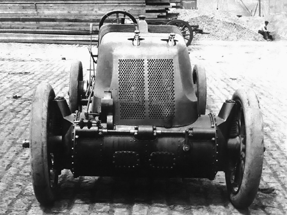
J. Walter Christie’s 1907 V-4 racer under construction at his shop in New York. The drive shaft for the water pump can be seen behind and to the right of the front wheel and extending toward the bottom of the radiator. This shaft was driven from the bevel gear visible in front of the first row of cylinders.

While the 1907 V-4 racer closely resembled the 1906 V-4 racer, it was an entirely new design. The car’s configuration followed that of the previous Christie racers in which the engine was mounted transversely between the two front wheels. The engine’s crankcase formed the car’s front axle and housed its transmission. The car had two forward gears: a normal gear for high-speed operation and a low gear. There was also a reverse gear. Behind the engine was a large radiator in which individual copper tubes were shaped in an inverted “U” and extended from one side of the frame to the other. A header tank was at the upper center of the tubes. The driver and passenger (typically a riding mechanic) sat over the rear axle with the fuel tank behind them.

The engine’s circular crankcase was made of nickel steel and formed an integral part of the chassis. The individual steel cylinders were mounted in two staggered rows on the crankcase. The first row of cylinders leaned back about 10 degrees from vertical, and the second row was angled about 45 degrees from the first row. Each cylinder was surrounded by a copper water jacket. Cooling water exited the top of each cylinder and flowed through a common manifold to the radiator’s header tank. After flowing through the radiator, the cooled water was pulled through a circulation pump and then flowed into the lower part of the cylinder water jacket. The water pump was driven from the camshaft via a long shaft with beveled gears.

Christie 1907 V-4 engine

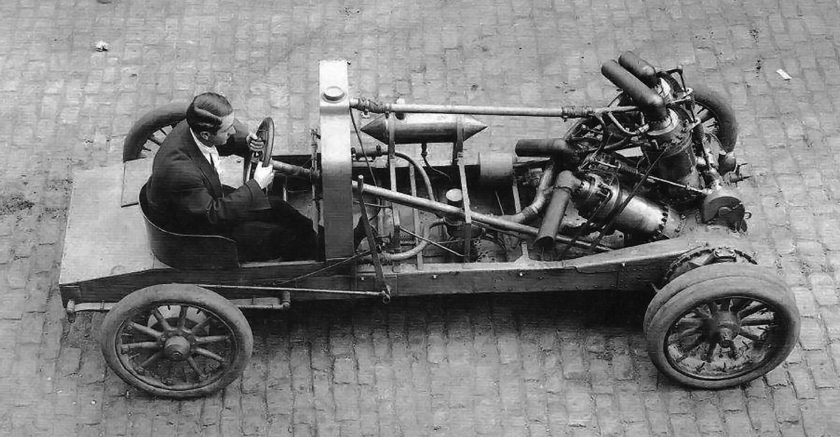
Detail view of the V-4 engine and how its crankcase was an integral part of the car’s frame. The cross shaft on the front of the crankcase drove low and reverse gears. Note the camshaft housing in front of the cylinders and the exhaust valve train. The camel hair lining can just be seen on the outer diameter of the flywheel housed in the crankcase. The clutch would be installed between the flywheel and the crankcase.

Each cylinder had one large, mechanically operated exhaust valve. Via a rocker arm and pushrod, all exhaust valves were actuated by a single camshaft mounted on the outside of the crankcase and in front of the first row of cylinders. From the driver’s position, the right side of the camshaft was geared to the crankshaft, and its left side was geared to the water pump drive shaft. Surrounding the exhaust valve were eight atmospheric (automatic) intake valves mounted in a manganese bronze inlet chamber. The incoming air/fuel charge flowed from the Breeze carburetor, which was positioned behind the engine, into a manifold that branched into separate intake pipes for each cylinder. This configuration gave each cylinder a different induction pipe length and led to unequal air/fuel distribution.

Many sources list the bore and stroke as 7-9/32 in (185 mm) and the total displacement as 1,214 cu in (19.9 L). However, the engine actually had a 7.25 in (184 mm) bore and stroke that gave a total displacement of 1,197 cu in (19.6 L). The 185 mm (7-9/32 in) figure probably originated from the European press rounding up the true 7.25 in (184 mm) number. Regardless, the car’s displacement was the largest of any Grand Prix racer before or since. The V-4 engine reportedly produced around 130 hp (97 kW), but it was probably closer to 100 hp (75 kW).

Christie 1907 V-4 front cowl

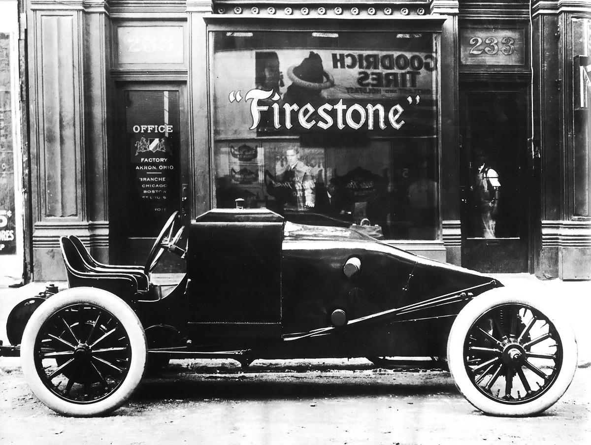
Christie’s V-4 racer with its full engine cowling. It seems the cowling’s grill was quickly cut away to increase airflow through the radiator. Each cylinder had short exhaust stacks, and the front cylinders expelled their exhaust through the top of the cowl.

The stagger of the cylinders allowed the use of a two-throw crankshaft. Two hollow steel connecting rods were attached to each throw. The crankshaft was supported by three main bearings. The steel pistons had concave heads and five rings; three rings were above the wrist pin, and two bronze rings were below. The underside of the piston had cooling fins to help dissipate heat. For each cylinder, a single spark plug was mounted on its Vee side near the pushrod guide. The spark plugs were fired by a battery-powered Heinz coil and communicator (distributor). The engine used splash lubrication and also a Petersen pressure feed oiler.

On each end of the crankshaft was a manganese bronze flywheel. The outer diameter of the flywheel was lined with woven camel hair to provide a friction surface. Covering the flywheel was a chrome steel cone clutch. Shafts and universal joints connected the drive wheels to the clutches and allowed for steering and independent coil spring suspension. Normal gear would lock the flywheel, clutch, and shaft together so that there was no reduction between the engine and drive wheels; for every revolution of the engine, the drive wheels turned one revolution. Normal engine speed was 1,000 to 1,200 rpm. With its 34 in (864 mm) by 4.5 in (114 mm) front tires, the car was capable of 120 mph (193 km/h) at 1,200 rpm. Of course, different size tires could be used to alter the vehicle’s acceleration and top speed. The rear tires were 34 in (864 mm) by 4 in (102 mm).

Christie 1907 V-4 French Grand Prix

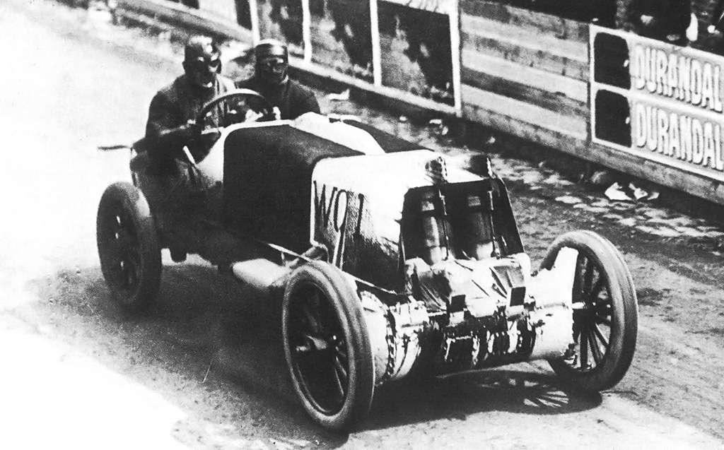
Christie and Lewis Strang running in the French Grand Prix in 1907. The car was painted white for the race, the engine cowl had been cut back, exhaust valve covers had been added to the top of the cowl, engine exhaust was now piped out of the cowl and into a muffler (of sorts) seen just behind the front wheel, and crankcase breathers had been added to the front of the car. Note the oil leaking from the camshaft and cross shaft housings.

Low and reverse gears were enabled by a cross shaft on the front of the crankcase. As the cross shaft slid laterally, gears on the shaft meshed with teeth cut into the outside of the clutch drums; at the same time, the clutch disengaged from the flywheel, allowing the speed of the drive wheels to be dictated by the speed of the cross shaft. The cross shaft was geared to the crankshaft at a reduced speed.

The car was only fitted with rear brakes, but two sets were employed. One set of rear brakes acted upon the inner surface of the brake drum while the other set acted upon the drum’s outer surface. The inner and outer brakes were controlled by individual foot pedals; however, the pedals were situated so that both could be pressed simultaneously by one foot.

The rear axle was a hollow steel tube and attached to the frame by semi-elliptic leaf springs. The 25 gal (95 L) fuel tank was easily removed so that it could be inspected by the Grand Prix committee. The car used a pressed steel, channel-section frame. It had a 110 in (2.79 m) wheelbase and a 53 in (1.35 m) track (some sources say a 100 in / 2.54 m wheelbase and a 56 in / 1.42 m track). The car weighed around 1,780 lb (807 kg).

Christie 1907 V-4 GP racer

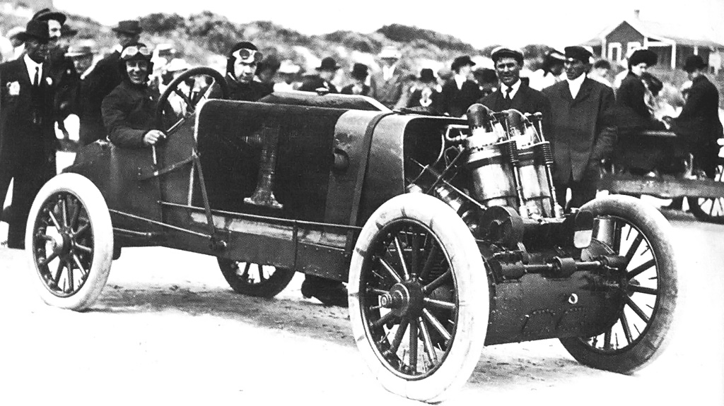
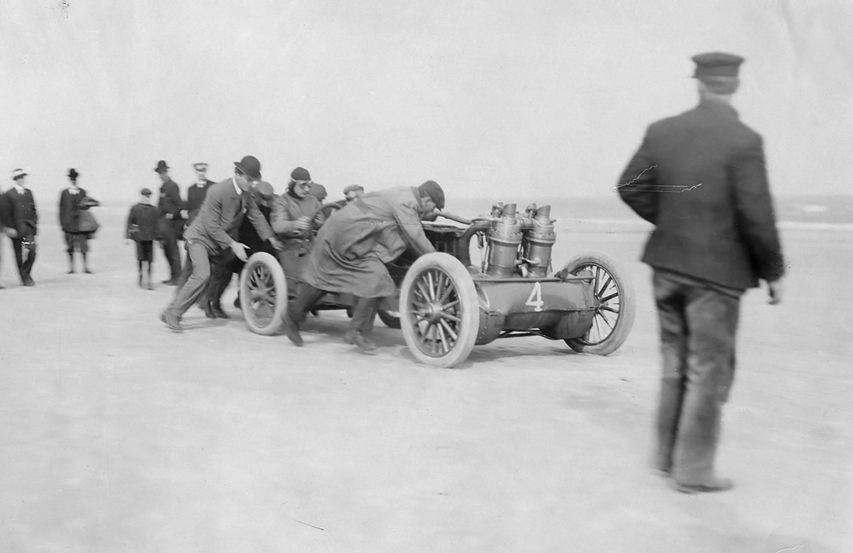
This photo was most likely taken soon after the racer returned from Europe (possibly at Morris Park, New York). The cross shaft, mufflers, and crank case breathers have been removed, but the rest of the car is still in its Grand Prix configuration—apparently still wearing white paint from the Grand Prix. Christie is in the driver’s seat. Note the oil still leaking from the front of the crankcase.

Completed in late April, the Christie racer was tested out on the streets of Long Island, New York at 4 AM. Lewis Strang, who was Christie’s ridding mechanic and nephew, accompanied Christie on this first run. Reportedly, the car broke down after about 20 mi (32 km), but the issues were not severe. The car was repaired and underwent further testing and refinement in May. The racer originally had a cowling that covered the entire engine. Due to cooling issues, the front of this cowling was removed to increase airflow through the radiator. This cowling was continually modified throughout the racer’s life.

In June, Christie, Strang, and the V-4 racer left for France. Thirty-eight cars were entered in the French Grand Prix to be run on 2 July 1907. The race consisted of 10 laps on a 77 km (47.8 mi) course laid out near Dieppe in Northern France. Christie’s racer was the lightest and one of the most powerful racers. It was allocated the race designation WC1 (for Walter Christie 1) and the 12th starting position. The Christie Direct Action Motor Car Company had arranged for several locals to assist with the racer. However, upon arriving in France, Christie and Strang discovered that the helpers were nowhere to be found. Christie and Strang spent their time repainting the car in the white and red colors required for United States racers. They then needed to register the racer in France. With all the administrative work completed, Christie and Strang did not have much time to practice and only made one test lap around the course. This session revealed a sticking exhaust valve, but there was no time for repairs.

Christie 1907 V-4 Oldfield

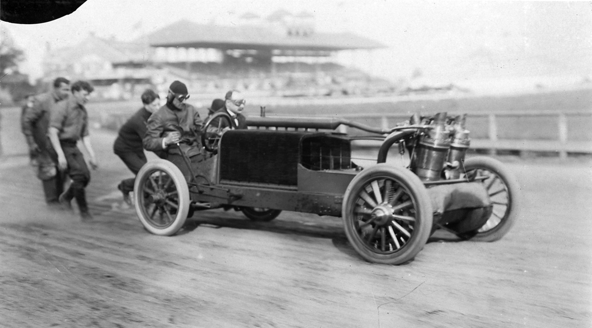
Barney Oldfield in the 1907 Christie V-4 racer. It is not known when or where this photo was taken, but a new engine cowling has been installed and the cross shaft has been reinstalled.

Christie and Strang started the race at 6:12 AM and had a tire failure less than two miles later; it was not a good start. Repairs were quickly made, but the car was struggling. Christie picked up the pace and ran a lap in 48 min and 49 sec (58.8 mph / 94.6 km/h). However, this was several minutes slower than the leader. Adding to the trouble of the sticking exhaust valve were a jammed clutch and an overheated main bearing. Christie and Strang retired the V-4 racer on the fifth lap.

Upon return to the United States, Christie was ridiculed for his poor showing at the Grand Prix. He responded that he had spent his own money on his effort, and, unlike other American auto manufactures, he “at least did something.” Christie went on to challenge his critics to a race “for any distance and for any amount of money, and at any time, on any road or track anywhere.” No one stepped up to accept his challenge.

Christie and Strang ran the racer at various tracks to prove its capabilities and those of the Christie Direct Action Motor Car Company. In August, Christie ran a 52.2 second mile (69.0 mph / 111.0 km/h) on the dirt track at Morris Park, New York. He then ran a 52 second lap (69.2 mph / 111.4 km/h) in Boston, Massachusetts followed by the same time at St. Paul, Minnesota. On 9 September, Christie and Strang were running at speed on the Brunots Track near Pittsburg, Pennsylvania when they struck a wrecked racer from a previous crash on the track. Christie lost control of the car, and both men were thrown from their racer. Strang was uninjured, but Christie was hospitalized with a broken wrist, a sprained back, a lacerated head, and abdominal injuries.

Christie 1907 V-4 Blakely Ormond

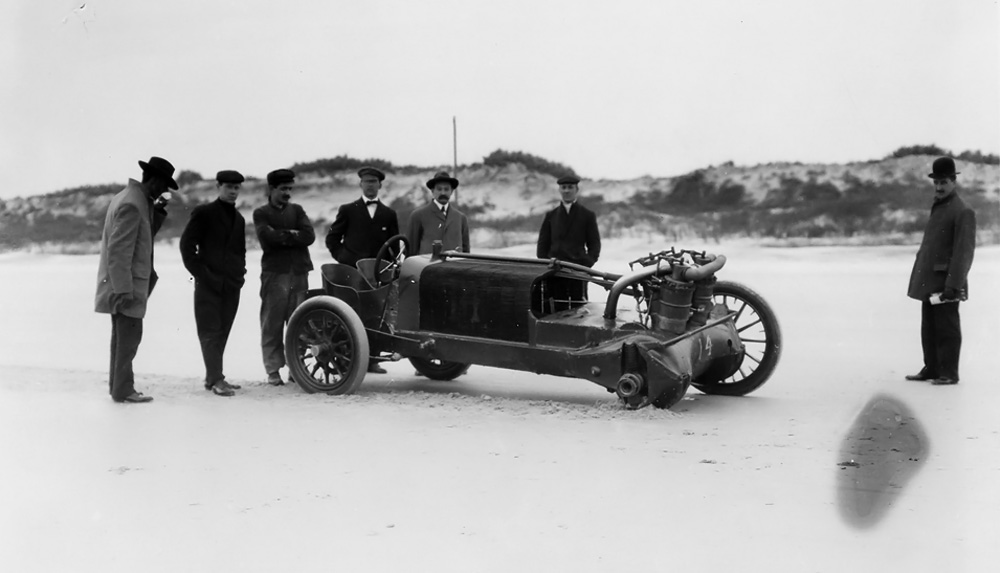
Ned Blakely sits behind the wheel of the Christie racer at Ormond Beach, Florida in March 1908. Although Christie made a 109 mph (175 km/h) test run, the car did not finishing any official race.

The V-4 racer was repaired, and Christie and Strang took the car to Birmingham, Alabama. Christie was still recovering from his injuries and did not drive much. The next stop was New Orleans, Louisiana, but the meet was delayed. Christie made arrangements to send the car back to New York and returned there himself. However, the car never arrived. Subsequently, Christie discovered that Strang had taken the car back to Birmingham, Alabama were he set a record on 16 October, lapping the mile track in 51.6 seconds (69.8 mph / 112.3 km/h). Strang also ran the V-4 racer at a few other events.

This unauthorized use of his car deeply upset Christie, and it was the end of his association with Strang. Some of Strang’s behavior can be attributed to the negative influence of his and Christie’s manager, William Pickens. To make matters worse, before Christie knew the car was missing, he had sold it to William Gould Brokaw. The arrangement allowed Christie to continue to drive the 1907 V-4 racer so long as he kept it in good repair. When Christie finally tracked down the missing racer and had it returned to his shop in New York, the engine had a cracked cylinder and other damage.

Christie 1907 V-4 late

An undated photo illustrating the many changes made to the 1907 V-4 racer. The cross shaft on the front of the crankcase and the engine cowling have been completely removed. A more conventional radiator has been installed along with new exhaust stacks. A much smaller fuel tank (just in front of the radiator) has replaced the original tank. Note the twin front tires on the right drive wheel. Race promoter Ernest Moross is behind the wheel.

Repairs (which included a new crankcase) were made, and Ned Blakely was tasked with racing the car at Ormond Beach, Florida in March 1908. Unfortunately, in a 100 mi (161 km) race on the first day of the event, a valve broke and took the car out of the race. Repairs were completed, but during a 256 mile (412 km) race on the third day, a spark plug broke off and damaged a cylinder, ending the racer’s participation at the event. Sometime during this event, Christie covered a mile in 33 seconds (109.1 mph / 175.5 km/h) on a test run, but it was not officially timed.

The car was again repaired. In early June, Morton J. Seymour was behind the wheel of the racer practicing for an event on Long Island, New York when he crashed and most likely overturned the car. The radiator was destroyed, but Christie managed to repair the car enough to run without cooling water for an attempt on the 1 km (.62 mi) record. Seymour covered the km in 26.6 seconds (84.1 mph / 135.3 km/h)—not fast enough for a new record.

Christie 1907 V-4 late track

Another view of the modified 1907 racer. The car still has the twin right drive wheels. Christie is in the driver’s seat. Note how the steering column passes through the radiator.

The racer was repaired yet again and further modified. A new (more conventional) radiator was installed. A small fuel tank was installed in front of the radiator, and the large, rear tank was removed. The low and reverse gears and the engine cowling were completely removed. Seymour and Christie went on to drive the car at a few events. After this, Christie and his good friend Barney Oldfield toured the country and made many appearances at various tracks.

At some point, after the new radiator, the V-4 racer had twin front right wheels installed to help the front-wheel drive vehicle on the circle tracks. It is not clear how often the car ran in this configuration. In December 1908, the racer was running at Tanforan Park near San Francisco, California, but a cracked cylinder took it and its driver Hughie Hughes out of competition. In January 1909, Hughes crashed the car at a race in Phoenix, Arizona, and that was the last known event for Christie’s 1907 V-4 racer; the car’s final disposition is not known. By this time, the Christie Direct Action Motor Car Company had fallen into receivership. Undaunted, Christie had established the Walter Christie Automobile Company in September 1908 and went to work on another V-4 racer.

Note: Some sources state that Blakely ran a 35 second mile in the 1907 V-4 racer at “a beach near Atlantic City” prior to March 1908. However, I was unable to find specifics to this event and feel it may have been confused with the 35.2 second run Christie made at Ventnor Beach, which is near Atlantic City, in 1905.

Christie 1907 V-4 DePalma Clark

A photo from the 1908 Minnesota State Fair with Christie, DePalma, and Clark. The fair was held in St. Paul from 31 August to 5 September. Note that the Christie racer has only one front right drive wheel.

Sources:
– “The Front-Wheel-Drives of John Walter Christie, Inventor” by Stan Grayson Automobile Quarterly Volume 14, Number 3 (1976)
– “America’s Candidate for the Grand Prix” by W. F. Bradley The Automobile (11 April 1907)
– “Grand Prix Failures 6. The 1907 Grand Prix Christie” The Bulletin of the Vintage Sports-Car Club No. 281 (Autumn 2013)
– “Christie Racer for the Grand Prix” The Automobile (21 February 1907)
– “The Grand Prix” The Automobile (11 April 1907)
– “Christie Racer is Being Tried Out” The Automobile (2 May 1907)
– “Florida’s Meet Supplied More Records than Races” by John C. Wetmore The Automobile (12 March 1908)
– “Christie’s New 100-Horsepower Racer” The Automobile (5 August 1909)
http://www.stohrdesign.com/christie-automobiles-1903-1909-a-blog (various pages)
http://blog.hemmings.com/index.php/2010/05/31/how-strang-met-his-death/
http://www.findagrave.com/cgi-bin/fg.cgi?page=gr&GRid=112329874
http://hclib.tumblr.com/post/9466387511/auto-racing-at-the-minnesota-state-fair-1908

Christie 1906 V-4 Strang Vanderbilt

Christie V-4 Engine 1906 Racer

By William Pearce

In the early 1900s, John Walter Christie built a series of front-wheel drive automobiles; each had its inline, four-cylinder engine mounted transversely between the front wheels. The engine’s crankcase also served as the vehicle’s axle. With only so much room between the wheels, the bore of the engine’s cylinders was limited, and Christie found that other cars were producing more power and outperforming his. In late 1905, Christie devised a way to increase the capacity and power of his engines by using a V-4 configuration.

Christie 1906 V-4 wheel Ormond Beach

J. Walter Christie’s 1906 racer after hitting debris on Ormond Beach, Florida in January 1906. Note the exhaust manifolds on the front of the engine, the original cylinder water jackets, and the lack of a radiator header tank. The induction pipe can be seen behind the engine.

After the Vanderbilt Cup race in October 1905, Christie took his 1905 racer, with the 828 cu in (13.6 L), 70 hp (52 kW) inline engine, and modified it with a new V-4 engine. Essentially, the axle of the 1905 racer was reworked to accommodate four individual cylinders. The car maintained its normal (high-speed) gear and low forward and reverse gears. The drive wheels were coupled to the crankshaft, and wheel slip was limited in the normal gear. For low gear and reverse gear, a five to one reduction was employed, and the drive wheels were allowed to slip relative to one another. The individual cylinders were arranged in two rows and were staggered to keep the engine compact. The cylinders were mounted to the top of the axle, and the angle between the rows was around 22.5 degrees.

The carburetor was placed low and behind the engine. The air/fuel mixture traveled from the carburetor and through a large pipe to the top center of the engine. Attached to the end of the pipe was an intake manifold with four outlets to provide the incoming air charge to each cylinder. The air/fuel mixture flowed into each cylinder though a single intake port that led to a chamber ringed around the outer cylinder head. In this ring were eight 1.5 in (38 mm) atmospheric (automatic) intake valves. A single spark plug was positioned below the inlet valve chamber ring.

Christie 1906 V-4 push Ventnor Beach

Christie behind the wheel of his racer at Ventnor Beach, New Jersey in April 1906 . The car had been modified with short exhaust stacks, redesigned cylinder water jackets, and a header tank above the radiator. It was here that Christie set a four-cylinder automobile speed record by covering a mile in 35.2 seconds (102.3 mph / 164.6 km/h).

At the center of the induction ring but separate from it was a single 3.125 in (79 mm) mechanically operated exhaust valve. The exhaust valve was controlled by a rocker arm actuated by a pushrod. The pushrods were driven from a camshaft situated behind the second row of cylinders. Originally, the exhaust valve was enclosed in a housing that had an exhaust port on its side. Each cylinder had its own exhaust manifold attached to the port; this configuration was replaced by a short exhaust stack that extended from the top of the cylinder.

The steel cylinders were originally surrounded by electrolytic (oxygen-free) formed copper water jackets. However, these jackets were prone to leaking and were replaced by jackets made of sheet metal. Water from the radiator entered the water jacket of each cylinder near its bottom. The water flowed out the top of each cylinder and into a common manifold that delivered it back to the radiator/header tank. The radiator was the same originally used with the inline engine in which copper tubes 5/16 in (8 mm) in diameter and 64 in (1.63 m) long were bent into an inverted “U” shape, extending from one side of the vehicle to the other. A header tank was later added above the middle of the radiator. Later still, the header tank was integrated into the middle of the radiator.

Christie 1906 V-4 push Empire

Lewis Strang push starting Christie in the 1906 V-4 racer at the Empire City Race Track in May 1906. On this track, Christie tied the then-current mile-track record of Barney Oldfield at 53 seconds (67.9 mph / 109.3 km/h). The racer is shown with an eight section radiator.

Sources disagree on the engine’s size, the engine’s power, and the car’s weight. Some sources list the engine as having a 7.375 in (187 mm) bore and stroke and a total displacement of 1,260 cu in (20.7 L). Other sources give a 7.5 in (191 mm) bore, a 7.0 in (178 mm) stroke, and 1,237 cu in (20.3 L) total displacement. The engine’s output varies by source between 100 to 135 hp (75 to 97 kW), but 100 hp (75 kW) is probably close to the correct figure. The car’s reported weight varies between 1,800 and 2,150 lb (816 to 975 kg). The crankshaft was 2.75 in (70 mm) in diameter and made of chrome steal. It was most likely a two-throw crankshaft supported by three main bearings. This would mean two connecting rods were attached side-by-side to one crankpin. The engine is said to have weighed 470 lb (213 kg).

Christie’s V-4 racer made its debut at Ormond Beach (north of Daytona Beach), Florida in January 1906. The car was numbered 14 for this event and experienced several issues. The right front wheel broke off after the racer struck some debris on the beach during a practice run. The car was repaired, but the copper water jackets leaked, and the car had engine cooling issues. Christie had to stop and refill the radiator with four miles left in the 30 mile race. Christie went on to finish the race in 37 minutes and 24.6 seconds, averaging 48.1 mph (77.4 km/h).

The car’s next appearance was in April at Ventnor Beach, near Atlantic City, New Jersey. The racer was now numbered 4 and was modified with new cylinder water jackets, open exhaust stacks, and the header tank above the radiator. Christie covered a mile in 35.2 seconds at 102.3 mph (164.6 km/h), making the racer the fastest four-cylinder automobile in the world. In May, Christie lapped the mile track at Empire City (Yonkers, New York) in 53 seconds (67.9 mph / 109.3 km/h). This speed tied the mile-track record held by Barney Oldfield.

Christie 1906 V-4 Strang Vanderbilt

Christie (at the wheel) and Strang ready for the Vanderbilt Cup race. Note the new header tank and the ten section radiator. Also visible are the springs on the pushrods that held the exhaust valves closed.

By September 1906, Christie had readied his V-4 racer for the Vanderbilt Cup. The car now had the integrated header tank installed, and the radiator had ten sections rather than the eight sections used earlier. George Robertson was to drive the car for the Vanderbilt Cup, but he crashed it during a qualifying run on September 15. The damage was not too severe, and Christie made the repairs that night. However, Christie did not notice that the steering arm had been cracked in the accident.

On the morning of 16 September, Christie and his riding mechanic (and nephew) Lewis Strang took the car out for a test run. As the car quickly gained speed, the steering arm failed and Christie lost control of the racer. The car smashed into a telegraph pole and was too damaged to be repaired. Fortunately, Christie and Strang were not injured. The pair went on to race in the 1906 Vanderbilt Cup in a converted touring car that the Christie Direct Action Motor Car Company had built. After the race, Christie went to work on his next racer; he had already set his sights on putting his front-wheel drive cars on the international stage.

Christie 1906 V-4 crash Vanderbilt

The destroyed Christie 1906 V-4 racer after the steering arm broke on 16 September. Note how the steering wheel was broken in the accident. Fortunately, Christie and Strang were not injured.

Sources:
– “The Front-Wheel-Drives of John Walter Christie, Inventor” by Stan Grayson Automobile Quarterly Volume 14, Number 3 (1976)
– “The Reconstructed Christie racer and Its Record at the Automobile Carnival” Scientific American (9 June 1906)
– “Record-Holding Racers at the Ormond Automobile Meet” Scientific American (10 February 1906)
– “Now for the Selection of the American Cup Team” The Motor Way (20 September 1906)
– “Christie’s New 100-Horsepower Racer” The Automobile (5 August 1909)
http://www.stohrdesign.com/christie-automobiles-1903-1909-a-blog (various pages)
http://www.vanderbiltcupraces.com (various pages)