Category Archives: Aircraft

savoia-marchetti s64 take off

Savoia-Marchetti S.64 and S.64 bis

By William Pearce

Inspired by Charles Lindbergh’s New York to Paris transatlantic flight of 3,600 miles (5,800 km) in May 1927, Italian pilot Arturo Ferrarin discussed with Alessandro Marchetti the possibility of building an aircraft to set non-stop distance records. Ferrarin was an experienced long distance flyer, having flown from Rome to Tokyo in 1920. Marchetti was the chief designer for Savoia-Marchetti and had complete control of the aircraft’s design and configuration. What emerged from Marchetti’s drafting table was the S.64. The Italian Air Ministry supported the project as a way to demonstrate the capabilities of Italian aviation to the world; two S.64 aircraft were ordered in late 1927.

savoia-marchetti s64 take off

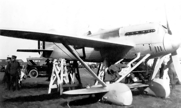
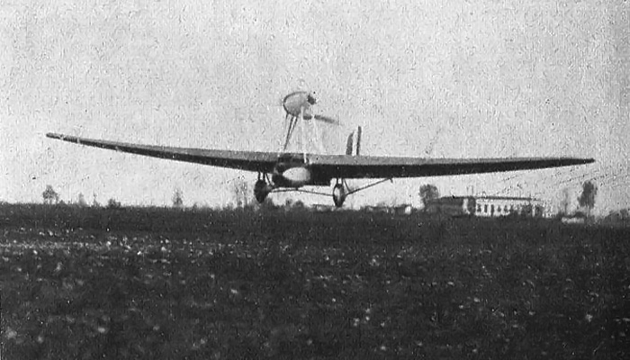
The Savoia-Marchetti S.64 taking off from Montecelio. The retractable radiator can be seen under the wing and just behind the fuselage nacelle.

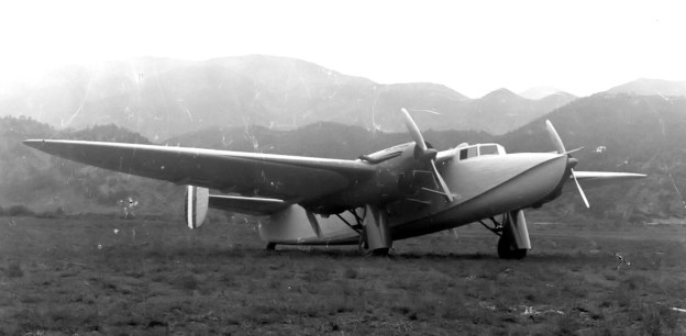
The Savoia-Marchetti S.64 was an aircraft of a rather unorthodox configuration yet similar to Marchetti’s earlier flying boat design, the S.55. Unlike the twin-hulled S.55 flying boat, the S.64 was a landplane. The S.64 consisted of a large, thick cantilever wing. A fuselage nacelle was blended into the center of the wing. The nacelle protruded below the wing and extended beyond its leading edge, but it was part of the wing’s structure. The pilot and copilot sat side-by-side and were provided with a rest area for long-distance flights. The wing and fuselage nacelle were made of wood and skinned with plywood. The wing housed 27 fuel tanks that combined to accommodate 1,717 gallons (6,500 L) of fuel.

Two frame booms made of duralumin extended behind the wing and supported the S.64’s slab horizontal stabilizer. Attached to the center of the horizontal stabilizer was the vertical stabilizer and rudder. Large control surfaces were attached to the trailing edge of both the horizontal and vertical stabilizers. Reportedly, the incidence of the horizontal and vertical stabilizers could be adjusted to trim the aircraft. The fixed main gear was faired and was suspended via struts under the wing. A tail skid was attached to the end of each boom.

savoia-marchetti s64 ferrarin del prete

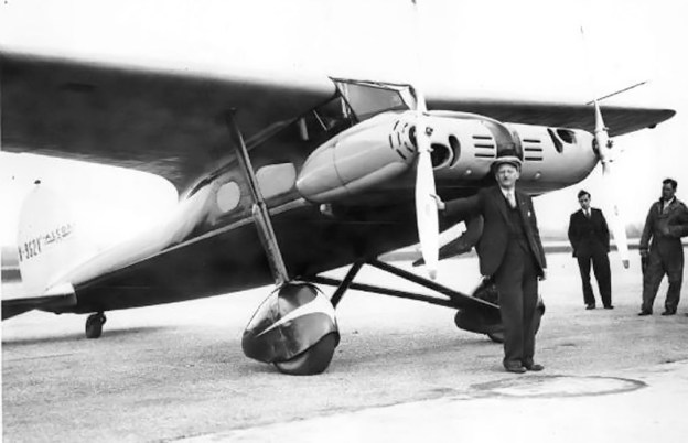
Arturo Ferrarin, Carlo Del Prete, and the S.64.

A single FIAT A.22T V-12 engine was supported on struts above the wing. The FIAT A.22T was liquid-cooled and had a 5.3 in (135 mm) bore and 6.3 in (160 mm) stroke. The engine displaced 1,677 cu in (27.5 L) and produced 550 hp (410 kW). With the exception of its valve covers, the engine was encased in a streamlined cowl. At the very front of the cowl was a large oil tank for the engine. The pusher engine turned a two-blade wooden propeller with a streamlined, pointed spinner. Coolant from the engine traveled down the supporting struts into a radiator under the rear of the wing. The semi-retractable radiator could be extended below the wing for increased airflow.

The S.64 had a 70.5 ft (21.5 m) wingspan and was 34.1 ft (10.4 m) long. The aircraft had an empty weight of 5,291 lb (2,400 kg). Its useful load was 10,141 lb (4,600 kg), resulting in a maximum weight of 15,432 lb (7,000 kg)—nearly three times its empty weight. Its top speed was 146 mph (235 km/h), and cruise speed was around 100 mph (160 km/h). Takeoff speed with a heavy load was 93 mph (150 km/h). The S.64’s maximum range was estimated as 7,146 miles (11,500 km).

savoia-marchetti s64 Brazil

Brazilians assist the S.64 after it landed on the beach near Touros.

The first S.64, registered as I-SAAV, was first flown on 3 April 1928 at Cameri airfield in northern Italy by Alessandro Passeleva. The aircraft was then flown by Arturo Ferrarin and Carlo Del Prete, two men who would become very experienced in the S.64. Initial flight tests revealed the aircraft had a high takeoff speed that necessitated a smooth runway. On 18 April, Ferrarin flew the S.64 to Aeroporto Alfredo Barbieri in Montecelio, near Rome, where a special 4,265 ft (1,300 m) runway had been prepared. The beginning of the runway was paved and had a 6.5 percent grade to aid the aircraft’s initial acceleration. The rest of the runway had a 0.56 percent grade and was unpaved. Flight testing continued with progressively larger fuel loads, and a larger 9.8 ft (3.0 m) diameter propeller was fitted

On 31 May, Ferrarin and Del Prete took off with 921 gallons (3,486 L) of fuel in an attempt to set a new closed circuit distance record. The circuit was from Casale dei Prati in Montecelio to the tower at Torre Flavia (west to the coast) then south to the lighthouse at Anzio (by the coast) and back to Montecelio. After 58 hours and 34 minutes, Ferrarin and Del Prete landed at Montecelio on 2 June after traveling 4,763.82 miles (7,666.62 km) at an average speed of 86.48 mph (139.18 km/h). The S.64, with Ferrarin and Del Prete, had set new records for endurance, distance, and speed over a 5,000 km course. The S.64 beat the endurance record set by Americans Edward Stinson and George Haldeman, who flew for 53 hours and 35 minutes in a Stinson Detroiter aircraft in late March 1928.

savoia-marchetti s64 bis

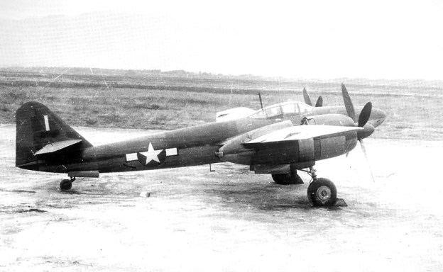
A side view of the S.64 bis illustrating the duralumin booms that attached the tail to the rest of the aircraft.

The S.64 was then prepared for its next record flight—a straight-line flight of over 5,800 miles (9,300 km) from Montecelio to Rio de Janerio, Brazil. However, that plan was changed on account of high temperatures in Montecelio that would have necessitated a longer takeoff run. The runway at Montecelio had already been extended by 1,312 ft (400 m); its length was now 5,577 ft (1,700 m), but that would not be enough. The new destination was Bahia (now Salvador), Brazil, some 5,280 miles (8,500 km) away. The shorter flight allowed the fuel load to be reduced by 370 lb (168 kg), from 8,377 lb (3,800 kg) to 8,007 lb (3,632 kg).

On the evening of 3 July, Ferrarin and Del Prete departed Montecelio and headed southwest. The S.64 traveled toward Gibraltar and then headed down the coast of Africa and out across the Atlantic. On the afternoon of 5 July, Ferrarin and Del Prete crossed the Brazilian coastline, only to discover thick fog below. After searching in vain for a landing strip, they went back to the coast and set the S.64 down on the beach near Touros, Brazil. Landing in the sand damaged the S.64’s landing gear and fuselage. Not accounting for the distance flown looking for a landing strip, the S.64 set a new straight-line distance record of 4,466.58 miles (7,188.26 km). The flight was 49 hours and 15 minutes. Later, the S.64 was taken by ship to Rio de Janerio and donated to Brazil. (Unfortunately, Del Prete died in Brazil on 16 August 1928 from injuries suffered in the crash of another aircraft. A monument honoring Del Prete and the S.64’s flight was built in the Praça Carlo Del Prete in Laranjeiras, Rio – Rio de Janeiro, Brazil.)

savoia-marchetti s64 bis flight

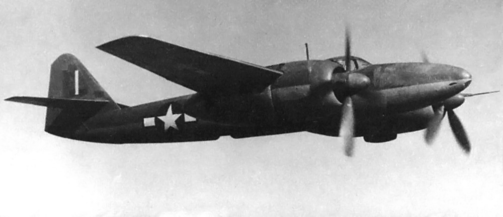
The S.64 bis in flight showing the similar engine, wing, and boom configuration to the S.55.

Later in July after the S.64’s flight to Brazil, the Germans took the S.64’s endurance record with Johann Risztics and Wilhelm Zimmermann flying for 65 hours and 25 minutes in a Junkers W 33. Italy wanted the record back, and so the second S.64 was built. Finished in early 1929, the aircraft was designated S.64 bis to indicate changes made from the first S.64. The S.64 bis had a longer windscreen and a variable-pitch metal propeller.

Umberto Maddalena and Fausto Cecconi were selected to fly the S.64 bis, registered as I-SAAT. While flight testing was delayed in late 1929 because of bad weather, the French pilots Dieudonné Costes and Paul Codos took the S.64’s distance record. Flying in a Breguet 19 in mid-December, Costes and Codos traveled 4,989.26 miles (8029.44 km). Now the challenge was to set new endurance and distance records, and the S.64 bis would not disappoint.

savoia-marchetti s64 bis landing

The Savoia-Marchetti S.64 bis coming in for a landing.

On 30 May 1930, Maddalena and Cecconi took off from Montecelio in the S.64 bis and followed the same closed circuit course that the S.64 had traveled. Landing on 2 June (the second anniversary of Ferrarin and Del Prete’s flight), Maddalena and Cecconi and the S.64 bis were the new endurance and distance record holders. Their 67 hour, 13 minute, and 55 second flight had covered 5,088.28 miles (8,188.80 km).

Unfortunately the S.64 bis would set no additional records. On 19 March 1931, Maddalena and Cecconi and radio operator Giuseppe Da Monte embarked on a flight from Cinisello (near Milan) to Montecelio. About halfway into their flight, near Pisa, a failure occurred and the S.64 bis crashed into the sea off Calambrone. It is believed that the FIAT’s crankshaft broke, allowing the propeller to cut into the wing and fuselage nacelle of the S.64 bis. However, a definitive cause was never found. Tragically, Maddalena, Cecconi, and Da Monte were killed in the crash.

Carlo Del Prete memorial

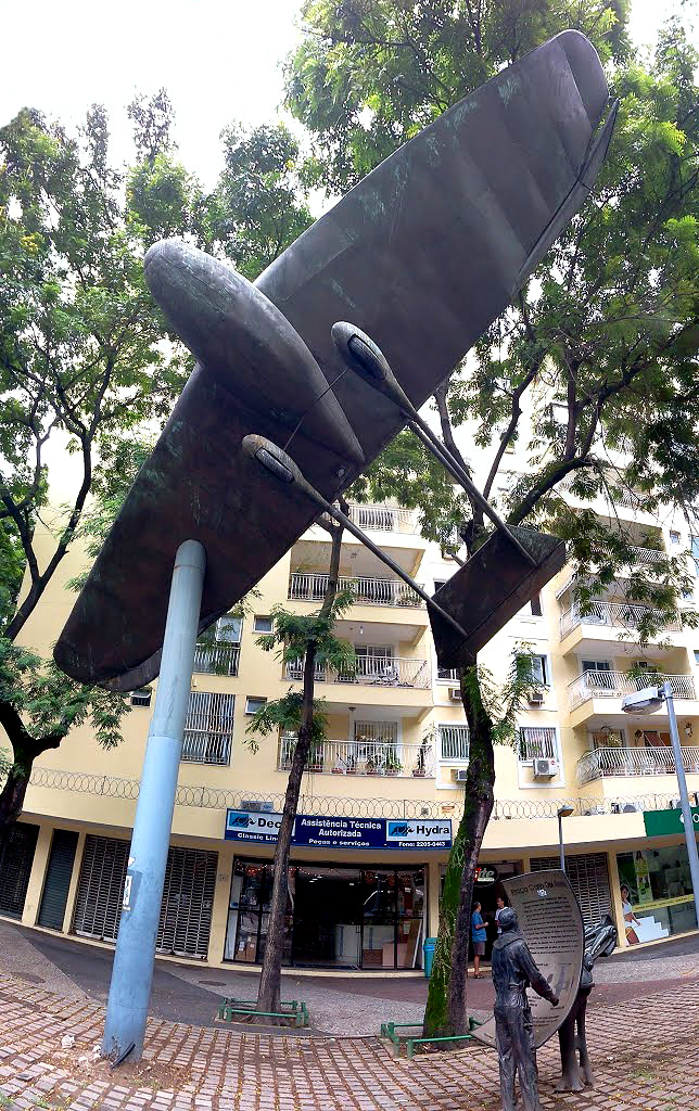
The Carlo Del Prete memorial in Rio de Janeiro, Brazil. A sculpture of the S.64 flies above a stature of Carlo Del Prete as he stands before a plaque detailing the record flight. (Silvio Cezar Scremin image)

Sources:
Aeroplani S.I.A.I. 1915-1930 by Giorgio Bignozzi and Roberto Gentilli (1982)
SIAI Pagine Di Storia (1976)
Italian Civil and Military Aircraft 1930-45 by Jonathan W. Thompson (1963)
Jane’s All the World’s Aircraft 1931 by C. G. Grey (1931)
“The Rome—Brazil Non-Stop Flight” Flight (12 July 1929)
“Well-known Italian Pilots Killed” Flight (27 March 1931)
“The Accident to the S.64” Flight (3 April 1931)
http://archive.is/cNtFo
http://en.wikipedia.org/wiki/Savoia-Marchetti_S.64

Myasishchev M-50 bottom

Myasishchev M-50 / M-52 Bounder

By William Pearce

In the midst of the cold war, the United States and the Soviet Union constantly sought to outdo one another or at least match each other. As the United States was developing the Convair B-58 Hustler bomber capable of Mach 2 speeds, the Soviet Union endeavored to design and build its own Mach 2 bomber. In 1955, the V. M. Myasishchev Experimental Design Bureau, or OKB-23 (Opytno-Konstruktorskoye Byuro-23), was tasked to develop the new Mach 2 strategic bomber. Under chief designer Georgi Nazarov and with the assistance of the TsAGI (Tsentral’nyy Aerogidrodinamicheskiy Institut, the Central Aerohydrodynamic Institute), a number of designs were evaluated and tested in a wind tunnel. Ultimately, a design was chosen that could meet the desired performance goals and was technically feasible to build. This aircraft became the Myasishchev M-50.

Myasishchev M-50 flyby

The Myasishchev M-50 with a MiG-21 escort, giving some perspective to the size of the M-50.

In general, the M-50 resembled an enlarged Mikoyan-Gurevich MiG-21. The M-50 was comprised of a long, slender fuselage with a large delta wing mounted in the middle. The fuselage had a circular cross-section with a bulge that ran down its spine for control and fuel lines. All fuel was housed in the fuselage and could be transferred between the extreme fore and aft tanks to counteract trim changes as the M-50 accelerated to or decelerated from supersonic flight.

The pilot and co-pilot sat in tandem at the very front of the aircraft. The M-50 was designed to operate at very high altitudes, and the crew was required to wear pressure suits in case of cabin depressurization or ejection. The aircraft was fitted with downward-ejecting seats. This configuration also facilitated crew entry and exit; the hatch under each seat opened and the seat lowered for access.

Myasishchev M-50 ground hatch

The M-50 with the hatches under the crew positions open. Also note the open bomb bay. The sole M-50 was painted with various radio call numbers.

The M-50’s wings were very thin and could not house any fuel. Under each wing was a pylon-mounted engine about 2/3 of the way toward the wingtip. On the top of the wing and above the engine pylon was a wing fence. Each wing had a second engine mounted at its tip. The wing was swept back 50 degrees from its root to the inboard engine and 41.5 degrees to the second engine at its tip (some sources say the sweep was 57.57 and 54.42 degrees respectively). The wing featured large, rectangular, double-slotted flaps and tapered outboard ailerons. Reportedly, when the flaps were deployed, the ailerons dropped down to further reduce the M-50’s landing speed. All three tail surfaces, including the vertical stabilizer, were all-moving. Each tail surfaces had an anti-flutter weight barb extending from its tip. All flight control surfaces were hydraulically operated.

The M-50’s landing gear was of bicycle configuration, with a four-wheel bogie located both fore and aft of the bomb bay. Additional forward retracting outrigger gear was mounted just inboard of each wingtip engine. In order to accommodate a weapons bay large enough to carry the 36 ft 1 in (11 m) long M-61 cruise missile, the rear main gear was placed near the tail, well behind the aircraft’s center of gravity. This gear placement drastically increased the speed needed for rotation at takeoff, perhaps even making takeoff impossible. To alleviate this issue, the M-50’s nose gear was equipped with a double-extension hydraulic strut. At 186 mph (300 km/h) the strut would automatically extend, rotating the aircraft 10 degrees nose-up. The gear also had an emergency steel skid that could be hydraulically lowered to the runway upon landing, acting as a drag anchor, in case there was an issue with the standard three-parachute braking system.

Myasishchev M-50 rear

A rear view of the Myasishchev M-50 showing its all-movable tail surfaces. Also note the hump that housed fuel and control lines running along the aircraft’s spine.

The M-50 was 188 ft 7 in (57.48 m) long, had an 82 ft 4 in (25.1 m) wingspan, and was 27 ft 1 in (8.25 m) tall. The aircraft’s empty weight was 173,855 lb (78,860 kg), and its maximum weight was 319,670 lb (145,000 kg). The M-50’s forecasted performance included a service ceiling of 45,930 ft (14,000 m), a range of 8,075 mi (13,000 km), a bomb load of 11,000 lb (5,000 kg), and a top speed of 1,210 mph (1,950 km/h), or Mach 1.84.

Construction of the M-50 began in April 1956. Originally, the M-50 was to be powered by four Zubets RD-16-17 afterburning turbojets with 40,765 lb (181.32 kN) of thrust. However, the aircraft’s construction outpaced the engine’s development. When the M-50 was rolled out in July 1958, four non-afterburning Dobrynin VD-7BA turbojets of 21,495 1b (95.61 kN) thrust had been temporarily installed. The aircraft was re-designated M-50A as a result of the engine change.

In October 1958, the M-50A was disassembled and moved to the Zhukovskiy flight test center. Here it underwent taxi tests that indicated further modifications were needed. After the modifications, M-50A finally took to the air on 27 October 1959 with Nikolay I Goryainov and A S Lipko at the controls. Initial flight testing progressed rapidly; however, the M-50A was damaged in a ground accident on 12 May 1960. During an engine run-up, the aircraft jumped its wheel chocks and collided with the parked Myasishchev 3ME bomber prototype. The 3ME was scrapped as a result of the damage, but the M-50A was repaired and flying again in two months.

Myasishchev M-50 bottom

The Myasishchev M-50 makes a pass at the Tushino Air Show on 9 July 1961. Note the similar layout of the M-50 and its MiG-21 escorts.

In April 1961, the two inner VD-7BA turbojets were swapped with afterburning VD-7AM engines of 35,275 lb (156.91 kN) thrust. Slightly derated VD-7BA engines of 20,945 lb (93.16 kN) thrust were installed on new wingtip mounts. These mounts were wingtip extensions that housed new rearward retracting outrigger gear and increased the wingspan by 32 ft 10 in (10 m) to 115 ft 2 in (35.1 m). All engine installations were redesigned to incorporate ram inlets above the nacelle for additional cooling airflow.

Flight tests continued. With the underpowered engines installed, the M-50A was unable to achieve supersonic flight. Even in a shallow dive from altitude, the aircraft’s speed would not go above Mach 0.99, or 650 mph (1,050 km/h). In addition, the M-50A’s range fell 2,110 mi (3,400 km) short of expectations to 5,965 mi (9,600 km). During flight tests, the sole M-50A was painted with a various radio call numbers—023, 022, 12, and 05—to confuse any western observers.

Myasishchev M-52 mock-up

The Myasishchev M-52 mockup. Note the side-by-side cockpit configuration and the missile positioned near its mount under the wing. The small horizontal stabilizer is barely visible on top of the tail.

On 9 July 1961, the M-50A was escorted by two MiG-21 fighters as it made a flyby pass at the Tushino Air Show near Moscow. Western observers were impressed by the large, exotic, and loud aircraft. This appearance resulted in NATO assigning the codename “Bounder” to the M-50. However, what the observers did not know was that this was the M-50A’s last flight. It had only flown 19 times.

The M-52, a further development of the M-50, had been under construction since November 1958. The M-52 retained the four Zubets RD-16-17 engines (some say RD-17-18 engines rated at 39,020 lb / 173.58 kN). The wingtip engines were mounted on larger extensions. The M-52 had side-by-side seating for the pilot and co-pilot, and a third crew member was stationed in its nose. A small, delta-shaped horizontal surface was added to the top of the vertical stabilizer. Planned weapon upgrades for the M-52 included twin tail guns and provisions to attach a cruise missile on each side of its fuselage, under the wings.

Myasischev_M-50_@_Central_Air_Force_Museum OMP

The Myasischev M-50 on display in the Central Air Force Museum at Monino Airfield. (Maarten image via Wikimedia Commons)

Soviet Premier Nikita Krushchev felt future offensive and defensive weapons would be based on intercontinental ballistic missiles (ICBMs) rather than strategic bombers. As a result, the Myasishchev M-50 and M-52 projects were cancelled. OKB-23 was closed, and its personnel were redirected to another organization for ICBM work.

The M-50A and the nearly finished M-52 eventually ended up parked at Ramenskoye Airport in Zhukovsky (near Moscow), Russia. In 1968, the M-50A was relocated to the Central Air Force Museum at Monino Airfield (also near Moscow) where it is currently on display. The M-52 was scrapped in the 1970s.

Below is a video of the Myasishchev M-50 uploaded to YouTube.

Sources:
Soviet X-Planes by Yefim Gordon and Bill Gunston (2000)
Aircraft of the Soviet Union by Bill Gunston (1983)
http://www.airvectors.net/avbison.html
http://www.testpilot.ru/russia/myasishchev/m/50/m50_e.htm
http://www.testpilot.ru/russia/myasishchev/m/52/m52.htm
Unflown Wings by Yefim Gordon and Sergey Komissarov (2013) *No real info on the M-50 or M-52 but does contain a number of other projects that are often attributed to these aircraft.

Skoda-Kauba V4

Skoda-Kauba V4, SK 257, and V5

By William Pearce

In early 1942, Austrian engineer Otto Kauba had interested the RLM (Reichsluftfahrtministerium or German Ministry of Aviation) in the design of a flying bomb. The RLM founded the Škoda-Kauba Flugzeugbau in German-occupied Prague, Czechoslovakia to produce the aircraft. Kauba was assigned to work out of the Škoda Auto Works, and the aircraft were to be built by the Czech company Avia. Although the flying bomb project was unsuccessful, Škoda-Kauba continued to design a series of small aircraft for the RLM, all of which were built by Avia. His next two designs yielded small and strangely shaped aircraft, but Kauba’s fourth design was a much more refined and sleek aircraft: the V4.

Skoda-Kauba V4

The Argus As 10C-3-powered Škoda-Kauba V4 was a sleek and attractive aircraft. Note the cut-out in the vertical stabilizer that allowed the variable incidence horizontal stabilizer to move.

The Škoda-Kauba V4 was designed to be a single-seat advanced trainer. It was an exceptionally clean low wing aircraft with retractable, wide-track main gear. The V4 employed simple construction and used non-strategic materials, such as steel, wood, and canvas. The wing’s leading edge was swept back and its tubular main spar tapered toward the rounded wingtip. Ribs were welded onto the main spar to form the basic frame of the wing, which was then covered with plywood. The fuselage had a welded steel-tube frame skinned with plywood. The V4 had a variable incidence horizontal stabilizer that was adjusted by the pilot via an electric motor for trim control. The V4 was powered by a 240 hp (179 kW) Argus As 10C-3 inverted, air-cooled, V-8 engine. Provisions were made to mount a single 7.9 mm machine gun.

The V4 had a wingspan of 24 ft 11 in (7.6 m) and a length of 18 ft 4 in (5.6 m). The aircraft’s maximum speed was 261 mph (420 km/h) at altitude and 236 mph (380 km/h) at sea level. Cruising speed was 196 mph (315 km/h). The SK 257’s initial rate of climb was 2,008 ft/min (10.2 m/sec). Its service ceiling was 24,600 ft (7,500 m), and it had a range of 578 miles (930 km). The aircraft weighed 2,249 lb (1,020 kg) empty and 2,756 lb (1,250 kg) loaded.

Skoda-Kauba V4 and SK 257

This image gives a good view of the differences between the V4 and the SK 257 prototype. Note the different wing shape and longer Argus As 410 engine and rear fuselage of the SK 257.

The V4, carrying the registration D-EZWA, exhibited good flying characteristics and performance. Since it was constructed from non-strategic materials, the RLM saw the makings of a good aircraft. However, the desire for more power could not be overlooked. The RLM awarded Škoda-Kauba a contract for the development of a more powerful advanced trainer, designated SK 257. The RLM believed the SK 257 would prepare new pilots for the challenging Messerschmitt Bf 109. Four SK 257 prototypes were ordered.

The SK 257 was very similar to the V4, although slightly longer and powered by a larger engine. The SK 257’s engine was an air-cooled, inverted, V-12 Argus As 410 that produced 485 hp (362 kW). Reportedly, the SK 257 had the same 24 ft 11 in (7.6 m) wingspan as the V4, but its wing had square tips and less sweep. At 23 ft 4 in (7.1 m), the SK 257 was 5 ft (1.5 m) longer than the V4. The aircraft had a maximum speed of 217 mph (350 km/h).

Skoda-Kauba SK 257 accident

Two production Škoda-Kauba SK 257 come to grief. Note the different tail and canopy when compared to the prototype and the absence of gear doors.

The four (some say two) SK 257 prototypes were completed and the first flew in 1943. The aircraft displayed excellent handling and performance. Subsequently, The RLM ordered 1,000 SK 257 trainers for the Luftwaffe. This order was quickly reduced to 100 aircraft. The production aircraft were built at Trenčin on the Biskupice airfield in Slovakia. The production SK 257 aircraft had a simplified square tail, whereas the prototypes had a curved tail. After five examples had been built, their construction was judged to be so poor that they did not pass the Luftwaffe quality control inspections, and the entire order was cancelled.

Undeterred, Kauba designed a fighter based on the V4/SK 257 aircraft. This fighter was designated V5 and was to be powered by a 1,750 hp (1,305 kW) Daimler-Benz DB 603 liquid-cooled inverted V-12 engine. The V5 was intended to out-perform the Focke-Wulf Fw 190 with a maximum speed of 475 mph (765 km/h). It would have a 40 ft (12.2 m) wingspan with two 20 mm cannons in each wing, be 32.8 ft (10 m) long, and weigh 9,920 lb (4,500 kg). However, the V5 progressed no further than a series of wind tunnel models and a full-scale mockup. The RLM was focused on other projects and felt the development of an entirely new piston-engine fighter was a waste of time, resources, and effort.

Skoda-Kauba V5 mock-up

The full scale mockup of the Škoda-Kauba V5 fighter. Note the Škoda-Kauba emblem that was also worn by all the prototypes and derived from the Škoda Auto Works emblem.

The only surviving piece of Škoda-Kauba’s efforts is the left wing, including landing gear, from a SK 257. This artifact is on display at the Vojenský Historický Ústav (Military History Institute) in Prague.

Skoda-Kauba SK 257 wing VHU

Preserved wing of a Škoda-Kauba SK 257 at Vojenský Historický Ústav in Prague. Note the tapered, tubular main spar protruding from the wing. (Vojenský Historický Ústav image)

Sources:
German Aircraft of the Second World War by J. R. Smith and Antony L. Kay (1972/1992)
Československá Letadla [1] 1918-1945 by Václav Němeček (1983)
http://www.histaviation.com/Skoda-Kauba.html and subpages
http://www.vhu.cz/exhibit/kridlo-z-nemeckeho-cvicneho-letounu-sk-257/

Sud-Ouest (SNCASO) SO.8000 Narval

By William Pearce

In the immediate aftermath of World War II, France worked to rebuild its military. Much progress had been made in aviation during the war years, and this was now an area of special focus. The French Navy (Marine Nationale) expressed an interest in a new aircraft that could serve in fighter, interceptor, and ground attack roles. Although other navies were beginning the transition to jet aircraft, the French Navy requested this new aircraft to be piston-powered.

Sud-Ouest SO8000 side

Side view of what is believed to be the first Sud-Ouest SO.8000 Narval, which was actually the second aircraft to fly. This image illustrates the good visibility provided to the pilot by the cockpit’s configuration. Note the radio antenna mast under the cockpit that was unique to the first aircraft.The aircraft is also lacking gear doors.

On 31 May 1946, the Société nationale des constructions aéronautiques du sud-ouest (often abbreviated as SNCASO or shortened to Sud-Ouest) was selected to design this new aircraft and build two prototypes. Arsenal de l’Aéronautique (Arsenal) was selected to develop its power plant. The original plan was to build five prototype aircraft followed by 65 production aircraft. Sud-Ouest moved quickly and designed an unusual single-engine pusher aircraft with twin booms supporting its tail. The aircraft was designated SO.8000 and given the name Narval (Narwhal).

Designed by Jean Dupuy, the SO.8000 was an all-metal aircraft. The inboard leading edge of its wing was sweptback 24 degrees, while the outboard section was sweptback 13.5 degrees and incorporated a dihedral angle. The aircraft had large double slotted flaps to decrease its landing speed for carrier operations. Roll control was achieved by a combination of small ailerons at the wingtips and spoilers. The twin booms extended from the inner wing sections and each supported a fin extending above and below the boom. The horizontal stabilizer spanned between the two tails and was attached near their top. On the second aircraft, which was the first to fly, the elevator was extended beyond the vertical tail fins and incorporated a horn balance.

Sud-Ouest SO8000 front

The first SO.8000 had its pitot tube located on an outrigger by the cockpit and not in the wing leading edge like the second aircraft. This view shows the Narval’s air inlets for its radiator and the air intake for its engine.

The pilot was enclosed in a sliding bubble-style canopy near the front of the aircraft. This configuration provided the pilot with an excellent view. Behind the cockpit and on each side of the aircraft were cooling air intakes for the radiator. After flowing through the radiator, the cooling air exited around the spinner of the eight-blade contra-rotating propellers. The air intake for the Arsenal 12H engine was located on the upper left side of the rear fuselage.

Lacking the time to design and test a completely new engine, Arsenal turned to the German Junkers Jumo 213A as a starting point. Arsenal reworked the Jumo 213 and created the 2,100 hp (1,566 kW) 12H. The 12H was an inverted V-12 with a 5.9 in (150 mm) bore, a 6.5 in (165 mm) stroke, and a displacement of 2,135 cu in (35.0 L). However, more power was desired, and Arsenal increased the 12H’s output to 2,250 hp (1,678 kW). This power increase caused some engine reliability problems. In 1948, the aircraft engine branch of Arsenal was absorbed by the Société nationale d’études et de construction de moteurs d’aviation (SNECMA), and the engine became the SNECMA Arsenal 12H.

Sud-Ouest SO8000 Narval

Another view of the first Narval illustrating its wing sweep and contra-rotating propellers.

The SO.8000 Narval was to be equipped with six 20 mm cannons in its nose. Additionally, underwing hard points would accommodate 2,205 lb (1,000 kg) of bombs. However, it is unlikely that the prototypes were ever armed. The SO.8000 had a 38 ft 7 in (11.75 m) wingspan and was 38 ft 9 in (11.80 m) long. On its tricycle landing gear, the aircraft stood 10 ft 6 in (3.20 m) tall. The Narval had an empty weight of 10,626 lb (4,820 kg) and a loaded weight of 15,432 lb (7,000 kg). The predicted performance of the SO.8000 was a maximum speed of 453 mph (730 km/h) at 24,606 ft (7,500 m) and a landing speed of 96 mph (155 km/h). The aircraft had an estimated 2,796 mi (4,500 km) range at 329 mph (530 km/h).

Sud-Ouest SO8000 rear

This image provides a good view of the first SO.8000’s elevator. Note how the horizontal stabilizer does not extend beyond the tail fins.

Most sources indicate that the second prototype (registered as F-WFKV) was completed and flew first, taking to the air on 1 April 1949 with Jaques Guignard at the controls. The first prototype’s first flight was on 30 December 1949 with Roger Carpentier (some sources say Jaques Guignard) as the pilot. The SO.8000 experienced numerous problems during its flight test program. The aircraft handled poorly and possessed some undesirable control characteristics, such as instability at low speed. Efforts were made to improve control and performance, including replacing the Chauvière contra-rotating propellers with a Rotol unit, but the results were still not satisfactory. In addition, the 12H engine proved to be unreliable. The flight tests revealed that the aircraft would not achieve its expected performance, and flight evaluations of the SO.8000 at the Centre d’Essais en Vol (Flight Test Center) in January 1950 were mostly unfavorable.

Given the trouble with the aircraft and the dominating performance of jet aircraft, further development of the SO.8000 was halted. A contributing factor in the Narval’s cancellation was the allocation of US Grumman F6F Hellcats and Vought F4U Corsairs to France. The second prototype took its 43rd and final flight on 8 January 1950. The first prototype was only flown twice. Proposals were submitted to convert the aircraft to jet-power as the SO.8010, but no further action was taken. Apparently, both SO.8000 aircraft were scrapped after the program was terminated.

Sud-Ouest SO8000 ground

In contrast to the image above, the elevator of the second SO.8000, which was actually the first to fly, can be seen extending past the tail fin in this view. The radio mast for the second aircraft was located on the back of the aircraft behind the cockpit, and note the pitot tube is on the far wing. In this image, the nose gear door has been attached but the main gear doors have not.

Sources:
The Complete Book of Fighters by William Green and Gordon Swanborough (1994)
French Secret Projects 1: Post War Fighters by Jean-Christophe Carbonel (2016)
Jane’s All the World’s Aircraft 1949-1950 by Leonard Bridgman (1949)
Aircraft Engines of the World 1951 by Paul H. Wilkinson (1951)
http://www.avionslegendaires.net/avion-militaire/sud-ouest-so-8000-narval/

Republic XP-47J front

Republic XP-47J Superbolt Fighter

By William Pearce

In mid-1942, Republic Aviation Corporation initiated a design study to lighten their P-47 Thunderbolt fighter for improved performance. The Thunderbolt had been steadily gaining weight as the design matured, while comparative enemy aircraft, like the Focke-Wulf FW 190A, were much lighter. Republic officially proposed a light-P-47 to the Army Air Force (AAF) on 22 November 1942. On 1 April 1943, the AAF gave Republic a letter of intent to purchase two light-weight P-47s, and the contract was officially approved on 18 June 1943. This new aircraft was designated the XP-47J.

Republic XP-47J front

An early image of the Republic XP-47J before the Superman nose art was applied. Note the cooling fan vanes around the spinner inside the cowling.

As with all P-47s, Alexander Kartveli was the main designer of the XP-47J, and he was assisted by Murray Burkow. The XP-47J was similar in appearance to a P-47B, but it was a completely new aircraft. The XP-47J had a close-fitting cowl installed around its Pratt & Whitney (P&W) R-2800 engine of increased power output. A large spinner was added, along with a fan to aid engine cooling. The turbosupercharger’s intake had been refined, and the flow of its exhaust was directed to provide additional thrust. Two of the .50-cal machine guns were deleted (leaving six) in the XP-47J’s lightened wing, and the rounds per gun were reduced to 267. Other weight-saving measures were the omission of radio equipment and the aft fuel tank. To keep the aerodynamics clean, the XP-47J had no provisions for external stores under the wings or fuselage.

Originally, the AAF wanted the XP-47J to have contra-rotating propellers and a bubble canopy, like a late P-47D. To expedite the XP-47J, the decision was made for the first prototype to be a razorback version and the second prototype would include a bubble canopy. The six-blade contra-rotating propeller was test-flown on a P-47B but showed no increase in performance. This, combined with delays at P&W on the R-2800-61 engine with a contra-rotating gear reduction, resulted in the substitution of a R-2800-57 engine with a standard gear reduction. Both the -57 and -61 engines were rated at 2,100 hp (1,566 kW) and had a War Emergency Power (WEP) rating of 2,800 hp (2,088 kW). The -61 engine would be supplied later, when it was available. The engine, cowling, and cooling fan were installed and test flown on a P-47D-15.

Republic XP-47J right

This side view of the XP-47J reveals its distinct intercooler air and exhaust exits under the rear fuselage.

The XP-47J had a wingspan of 40 ft 10 in (12.4 m) and a length of 33 ft 3 in (10.1 m). The aircraft had an empty weight of 9,663 lb (4,383 kg) and a design gross weight of 12,400 lb (5,625kg). Its service ceiling was 45,000 feet (13,716 m). The XP-47J had a range of 765 mi (1,231 km) at a cruising speed of 400 mph (644 km/h) and a range of 1,070 mi (1,722 km) at optimum cruising speed. Fuel capacity was 287 US gal (1,086 L).

On 31 July 1943, Republic issued a report comparing the estimated performance of the XP-47J with the P&W R-4360-powered XP-72 that was under development. The report concluded that the Republic XP-72 had more potential and recommended resources be focused on that aircraft. In addition, 70% of the P-47 production line needed to be re-tooled in order to produce the P-47J. Republic called for the cancellation of the second XP-47J prototype but encouraged the completion and testing of the first prototype. The AAF approved Republic’s plan and cancelled the second XP-47J.

The sole XP-47J prototype (serial number 43-46952) was completed in mid-November 1943 and made its first flight on the 26th of that month. The aircraft was quickly dubbed Superbolt and wore nose art on both sides of the cowling of Superman holding a lightning bolt. After about 10 hours of flying time, the R-2800-57 engine was making metal and was replaced by another engine of the same type in February 1944.

Republic XP-47J run-up

The factory-fresh Superbolt is being run-up outside of Republic’s plant in Farmingdale, New York. Unlike a standard P-47, the intake under the engine was separate and pushed back from the front of the cowling.

A short time later, P&W informed the AAF and Republic that the R-2800-57 engine was not compatible with the 2,800 hp (2,088 kW) WEP rating. A water-injected R-2800-14W was substituted in the XP-47J in April. Water injection is a system that sprays anti-detonation fluid (a mixture of alcohol and water) into the induction system to lower the charge temperature and prevent detonation in the cylinders. This allowed the -14W to produce 2,800 hp (2,088 kW). In March, P&W informed Republic that it was still having difficulty with the R-2800-61’s contra-rotating gear reduction and did not know when the engine would be available. This effectively put an end to the possibility that the XP-47J would have contra-rotating propellers anytime in the near future.

On 11 July 1944 and equipped with a General Electric CH-3 turbosupercharger, the XP-47J achieved 493 mph (793 km/h) at 33,350 feet (10,165 m). Although the engine was producing 2,800 hp (2,088 kW), Republic believed the aircraft had more potential. At its own expense, Republic installed a CH-5 turbosupercharger and a larger 13 ft (3.96 m) Curtiss propeller. The propeller was an experimental unit with 2 in (51 mm) added to its trailing edge to increase its width. With the changes, the engine producing 2,730 hp (2,036 kW), and 400 lb (1.78 kN) of jet thrust from the exhaust, Mike Ritchie flew the XP-47J over a calibrated course at 34,450 (10,500 m) feet on 4 August 1944* and achieved 505 mph (813 km/h). This is the highest speed recorded in level flight by any propeller-driven aircraft during World War II.

Republic XP-47J rear

The Republic XP-47J, now with the Superman nose art. Some differences from a standard P-47 are the additional plexiglass panel behind the pilot and the lack of intercooler exhaust doors on the sides of the rear fuselage.

The XP-47J was handed over to AAF and arrived at Wright Field, Ohio on 9 December 1944. During flight tests, the AAF was unable to get maximum power from the R-2800 engine. The AAF recorded a speed of only 484 mph (779 km/h) at 25,350 feet (7,727 m) and with the engine producing 2,770 hp (2,066 kW). Near the end of flight testing, the exhaust manifold system had a serious failure while the aircraft was at 36,000 ft (10,943 m). The cause of the failure was the increase in pressure and temperature from the CH-5 turbosupercharger acting upon the unstrengthened exhaust system. The Official Performance Summary report states the XP-47J had a max speed of 507 mph (816 km/h) and a 4,900 fpm (24.9 m/s) initial rate of climb. Republic’s Test Report No. 51 (27 January 1945) lists the max speed as 502 mph (808 km/h).

While the XP-47J Superbolt had remarkable performance, it was overshadowed by other aircraft, like the XP-72, that were under development. Work on the XP-72, which first flew on 2 February 1944, was not far behind that of the XP-47J, but as the war progressed and with the advent of jet fighters, neither aircraft were needed.

*Mike Ritchie’s report recording the 505 mph (813 km/h) speed was dated 5 August 1944, but it is believed the flight actually occurred on 4 August 1944.

Republic XP-47J front left

The six wing guns are evident in this image of the 500+ mph Republic XP-47J Superbolt.

Sources:
Republic’s P-47 Thunderbolt by Warren M. Bodie (1994)
US Army Air Force Fighters Part 2 by William Green and Gordon Swanborough (1978)
R-2800: Pratt & Whitney’s Dependable Masterpiece by Graham White (2001)
The American Fighter by Enzo Angelucci and Peter Bowers (1985/1987)
– “500-Mph. P-47 Disclosed by AAF” Aviation News (29 October 1945)
http://www.joebaugher.com/usaf_fighters/p47_9.html

Alcor Duo-6 Lockheed

Alcor Duo-4, Duo-6, and C-6-1 Transports

By William Pearce

In 1929, the Lockheed Aircraft Corporation was bought by the Detroit Aircraft Corporation. Lockheed’s founder, Allan H. Loughead (phonetically pronounced Lockheed) was unhappy with the acquisition and had voted against it. Allan left and formed a new company in 1930 with his brother Malcolm. The pair had worked together in aviation before pursuing separate interests in the 1920s. The new company was known as the Lockheed Brothers Aircraft Corporation.

Alcor Duo-4 front

The Duo-4 with “Olympic” written on the nose. Note the cooling slits for the Menasco Pirate engines.

Their first aircraft was the Olympic Duo-4, and its fuselage was similar to the Lockheed Vega 5. In place of the Vega’s single radial engine were two Menasco C4 Pirate engines. These in-line, four-cylinder engines were air-cooled and produced 125 hp (92 kW). The engines were positioned in the nose of the Duo-4 so that the tips of the propellers cleared each other by about 3 in (76 mm). The engines were laid on their sides so that their heads were close together and the crankshafts were farthest apart and canted out at a slight angle. The Duo-4’s engine arrangement had less air resistance than a normal twin-engine plane. In addition, when one engine was shut down, the Duo-4 behaved much like a single-engine aircraft.

The four to six passenger Duo-4 was a high-wing cantilever monoplane. The monocoque fuselage had a wooden structure and was covered with a plywood skin that was molded under pressure. The wings also had a wooden structure and were covered with plywood. The aircraft (registered as NX962Y) was first flown by Frank Clarke in 1930. In March 1931, the Duo-4 was damaged when a sudden gust of wind caused it to nose-over and then collide with a vehicle during a landing at Muroc (now Edwards Air Force Base), California. Unfortunately, this incident caused investors to back away from the Lockheed Brothers Aircraft Corporation, and funds were not available to quickly repair the Duo-4.

Alcor Duo-4 Pancho Barnes

The Olympic Duo-4 at Muroc Dry Lake with Florence “Pancho” Barnes. Note that “Olympic” no longer appears on the nose and the propeller tip clearance.

Over the next few years, the Duo-4 was slowly repaired and modified. The four-cylinder Pirate engines were replaced by six-cylinder Menasco B6S Buccaneer engines. The supercharged, 230 hp (171 kW) Buccaneers were in-line, air-cooled engines and turned 7 ft 6 in metal propellers. After the modifications, the aircraft was renamed the Duo-6 (some sources refer to it as the Loughead Alcor). It flew again in early 1934.

Allan Loughead officially changed his name to Allan Lockheed in February 1934. Also in 1934, the Lockheed Brothers Aircraft Corporation went out of business, but Allan continued with the Duo-6. In May 1934, one propeller was removed to demonstrate the Duo-6’s single engine performance. At Mines Field (now Los Angeles International Airport), the Duo-6 took off in 1,200 ft (366 m) and attained 130 mph (209 km/h) on just one engine. Reportedly, with one engine shut down, the aircraft handled with little yaw, much like a single-engine plane. In May, Allan flew the Duo-6 back east to demonstrate it to the Navy and Army. However, nothing came from this exposure.

Alcor Duo-6 Lockheed

The Duo-6 on its trip back east with Allan Lockheed in front. Note that “Alcor” is written on the tail and the changes to the engine cowling from the Duo-4 image above.

In October 1934, the United States placed operating restrictions on single-engine transports carrying passengers. This regulation marked a permanent shift to multi-engine transports for passenger service. Presumably, the twin-engine Duo would have done well under the new regulations with its ability to perform like a conventional single-engine aircraft in the event of one engine being shut down. Unfortunately, the Duo-6 crashed in late 1935 and was not repaired.

The Duo-4 and Duo-6 had a 42 ft (12.80 m) wingspan and were 28 ft 6 in (8.69 m) in length. The Duo-4 had an empty weight of 2,265 lb (1,027 kg). The aircraft had a max speed of 140 mph (225 km/h) and a landing speed of 47 mph (76 km/h). The Duo-6 had an empty weight of 2,885 lb (1,309 kg) and a gross weight of 5,090 lb (2,309 kg). The aircraft had a max speed of 183 mph (295 km/h), a cruise speed of 157 mph (253 km/h), and a landing speed of 57 mph (92 km/h). The service ceiling was 18,500 ft (5,639 m) and its range was 660 mi (1,062 km). The single engine performance of the Duo-6 was a max speed of 125 mph (201 km/h), a cruise speed of 100 mph (161 km/h), and a ceiling of 6,400 ft (1,951 m).

Alcor C-6-1 top

This unique top view of the C-6-1 doing an engine run shows how the engine nacelles were blended into the nose and wings.

In February 1937, Allan started a new aviation company: the Alcor Aircraft Corporation. The “Alcor” came from Allan Lockheed Corporation. Alcor’s first official aircraft (the Duo-6 had been built before the company was formed) was the C-6-1 Junior Transport. It was designed to carry six to eight passengers. The C-6-1 used the engine installation of the Duo but with improved C6S-4 Super Buccaneer engines that produced 275 hp (205 kW) at 2,400 rpm for takeoff. Each engine was canted out 4 degrees and the propellers cleared each other by 12 in (0.3 m).

The aircraft had a low-wing, and the main gear retracted back into the wing with the wheels turning 90 degrees to lay flat. The wings and fuselage had a structure made mostly of wood. However, there were some components in high-stress areas that were made of metal. The fuselage had a circular section and was made up of laminated spruce framework with a two-piece plywood skin that was molded under pressure. The engines were closely cowled and faired into the nose and wing. The C-6-1 was a streamlined aircraft that was very efficient and had excellent flight characteristics.

Alcor C-6-1 side

Side view of the Alcor C-6-1 Junior Transport complete with spinners.

The Junior Transport had a wingspan of 49 ft (14.94 m) and a length of 31 ft 8 in (9.65 m). The aircraft had an empty weight of 4,141 lb (1,878 kg) and a gross weight of 6,200 lb (2,812 kg). The aircraft had a max speed of 211 mph (340 km/h) at 5,500 ft (1,676 m) and a cruise speed of 190 mph (306 km/h) at 5,500 ft (1,676 m) and 200 mph (322 km/h) at 10,000 ft (3,048 m). The service ceiling was 24,000 ft (7,315 m) and its range was 835 mi (1,344 km). On one engine, the C-6-1 had a top speed of 147 mph (237 km/h), could cruise at 129 mph (208 km/h), and had a ceiling of 12,600 ft (3,840 m).

The C-6-1 (registered as NX15544) was first flown on 6 March 1938. On a test flight over San Francisco Bay on 27 June 1938, the C-6-1 went out of control during a high-speed dive. The dive test was instigated by the pilot and not part of the flight schedule. Unable to regain control, the pilot and observer bailed out, leaving the sleek C-6-1 to crash into the bay. The aircraft was insured, but the funds were only sufficient to pay off Alcor’s debts. With no capitol, Allan closed out Alcor. Allan continued to be involved in aviation for the rest of his life, but he did not build any further aircraft of his own design.

Even though the Duo-4 and Duo-6 were built under Lockheed Brothers Aircraft Corporation name, they are often referred to as the Alcor Duo-4 and Alcor Duo-6. In addition, the Alcor C-6-1 is often incorrectly referred to as the Lockheed Alcor.

Alcor C-6-1 flight

Alcor C-6-1 on a fight over San Francisco Bay. The San Francisco Bay Toll-Bridge (now San Mateo–Hayward Bridge) can be seen in the background. Note the absence of spinners on the otherwise sleek aircraft.

Sources:
Jane’s All the World’s Aircraft 1932 by C.G. Grey
Jane’s All the World’s Aircraft 1934 by C.G. Grey
Jane’s All the World’s Aircraft 1938 by C.G. Grey and Leonard Bridgman
Lockheed Aircraft since 1913 by Rene J. Francillon (1982/1987)
– “Commercial Aviation: An American Feeder-Line Machine,” Flight 6 July 1934
– “A ‘Flat’ Engined Transport,” Flight 12 May 1938
http://1000aircraftphotos.com/Contributions/HornDavid/9336.htm
http://www.aerofiles.com/_al.html
Brief Allan Lockheed 1910-1942 Autobiography
http://en.wikipedia.org/wiki/Allan_Loughead

Mitsubishi Ki-83 side

Mitsubishi Ki-83 Heavy Fighter

By William Pearce

In May 1943, the Japanese Army Air Force issued a specification for a high altitude, long range heavy fighter. Led by Tomio Kubo, a team at Mitsubishi began to design the single-engine Ki-73 (Allied codename: Steve) to meet this specification. However, the aircraft’s power plant, a 2,600 hp (1,939 kW) Mitsubishi Ha-203-II 24-cylinder “H” engine, suffered from severe developmental delays and was ultimately abandoned. As a result, the Ki-73 was abandoned as well.

Mitsubishi Ki-83 flight

The Mitsubishi Ki-83 on a test flight with US markings on the fuselage. The brace from the horizontal stabilizer to the fuselage can barely be seen. The notch in the underside of the fuselage should be the access hatch for the second crew member. Apparently the hatch was missing on this flight, as a hatch made mostly of acrylic glass should be visible in other images.

Kubo went back to the drawing board and created another designed based on his experience with twin-engine aircraft, including the Mitsubishi Ki-46 (Allied codename: Dinah). What Kubo designed was perhaps the most advanced Japanese aircraft built during World War II: Mitsubishi Ki-83.

The Ki-83 was an aerodynamically clean, all metal aircraft with two crew stations. Its mid-fuselage mounted wings were equipped with Fowler-style flaps. The pilot had a 360-degree view, and the radio operator/navigator was positioned in the aircraft’s fuselage behind the wings. The second crew member had very cramped accommodations with small windows. However, the second crew member was not intended to be on every mission.

The aircraft featured fully retractable gear including the tailwheel. The main wheels retracted back into the engine nacelles. The Ki-83’s armament consisted of two 30 mm Ho-105 and two 20 mm Ho-105 cannons, all housed in the lower nose. In addition, two 110 lb (50 kg) bombs could be carried on under-wing hardpoints. Some sources say the bombs were carried internally, but this appears unlikely unless the bombs replaced the second crew member.

Mitsubishi Ki-83 rear

The Ki-83 still in Japanese markings. The windows for the second crewman can be seen just above the tip of the horizontal stabilizer. Presumably, this is an early photo of the Ki-83, because the brace for the horizontal stabilizer appears to be absent.

The Ki-83 was powered by two Mitsubishi Ha-211-IRu (joint designation [Ha-43] 12) air-cooled radial engines, each driving an 11.5 ft (3.5 m), four-blade propeller. The 18-cylinder engines had a bore of 5.51 in (140 mm), a stroke of 5.90 in (150 mm), and a total displacement of 2,536 cu in (41.6 L). The engine was turbosupercharged and produced 2,200 hp (1,640 kW) for takeoff and 1,750 hp (1,305 kW) at 31,170 ft (9,500 m). The turbocharger was placed in the rear of the engine nacelle. Fresh air would enter the turbocharger near the rear of the nacelle on the outboard side, be compressed, and then flow to the engine through an air box in the upper nacelle. The engine’s exhaust was expelled from the turbocharger on the inboard side of the nacelle, and a wastegate was positioned at the end of the nacelle. The exhaust arrangement provided some additional thrust. An engine oil cooler was positioned under the nacelle.

The Ki-83 had a 50.85 ft (15.5 m) wingspan, was 41.0 ft (12.5) long, and weighed 13,184 lb (5,980 kg) empty and 20,790 lb (9,430 kg) maximum. A speed of 426 mph (686 km/h) was recorded at 26,250 ft (8,000 m), but top speed rose to 438 mph (705 km/h) at 29,530 ft (9,000 m). Cruise speed was 280 mph (450 km/h) at 13,125 ft (4,000 m). The Ki-83 could climb to 32,810 ft (10,000 m) in 10 minutes and had a ceiling of 41,535 ft (12,660 m). Normal range was 1,214 mi (1,953 km), and maximum range was 2,175 mi (3,500 km).

Mitsubishi Ki-83 hangar

Another early image of the Mitsubishi Ki-83 in Japanese markings. Curiously, there seem to be no oil coolers under the engine nacelles.

The first Ki-83 prototype was completed in October 1944 and flew the following month on 18 November. Test flights were often interrupted by Allied bombing raids, but the Ki-83 demonstrated excellent maneuverability and performance. However, the prototype did experience tail and engine vibration issues and failures of the turbochargers. To cure the issues with the tail, an angled brace was added from the horizontal stabilizer down to the fuselage, and balance weights were added to the elevators. Based on the Ki-83’s performance, the Japanese Navy expressed interest in the aircraft, and the Army agreed to give the Navy some examples after production had started. Reportedly, 39 Ki-83 aircraft had been ordered.

Three additional prototypes were built that incorporated changes to fix the first Ki-83’s deficiencies. The second Ki-83 was completed in April 1945 and flew on 9 March 1945. The third and fourth prototypes had their first flights in the summer of 1945. However, the three additional prototypes were damaged (most likely destroyed) in Allied bombing raids. A fifth prototype was under construction at the end of the war.

Mitsubishi Ki-83 side

The captured Ki-83 while still in Japan. The wastegate exhaust is visible at the rear of the nacelle, and the air intake can be seen on the outboard side of the nacelle just below the trailing edge of the wing.

With the war situation deteriorating for Japan, their limited resources were dedicated to the production of interceptor fighters, and the Ki-83 never entered production. At the end of the war, US forces were surprised to find the Ki-83 because it was an aircraft they knew nothing about. In addition, an advanced high-altitude interceptor version, the Ki-103, and a reconnaissance version, the Ki-95, were under development. The original and sole remaining Ki-83 was flight tested by the Allies at the Matsumotu Army Air Base in Japan. On one of those flights and with the aid of high-performance US aviation fuel, the Ki-83 reportedly achieved a top speed of 473 mph (762 km/h) at 22,965 ft (7,000 m) and could climb to 32,810 ft (10,000 m) in 9 minutes, but a definitive source reporting this impressive performance has not been found.

After flight testing, the Allies came to the conclusion that the Ki-83 was a very maneuverable and high-performance aircraft. In December 1945, the Ki-83 was shipped to the Alameda Air Station near San Francisco, California aboard the USS Tulagi escort carrier. The Ki-83 was given the Foreign Evaluation number FE-151 and flown some in the US. By February 1946, it was at the Middletown Air Depot (now Harrisburg International Airport) at Middletown, Pennsylvania and available for examination by the US aircraft industry. In September 1946, the Ki-83 was allotted to the Air Force Museum, but evidently these plans fell through. The Ki-83’s last known whereabouts were at Orchard Field Airport (now O’Hare Airport) Special Depot in Park Ridge, Illinois in 1949. There are no further details of its fate and it is presumed to have been scrapped at Park Ridge in 1950.

Mitsubishi Ki-83 guard

Mitsubishi Ki-83 under guard by US forces in Japan. The 30 mm cannons are in the lower nose with the 20 mm cannons above. The turbocharger exhaust can just be seen at the rear of the nacelle in the center of the image.

Sources:
Japanese Aircraft of the Pacific War by Rene J. Francillon (1970/2000)
Japanese Army Fighters Part 1 by William Green and Gordon Swanborough (1977)
Japanese Aircraft: Performance and Characteristics by Edward T. Maloney (2000)
War Prizes by Phil Butler (1994/1998)
http://www.secretprojects.co.uk/forum/index.php/topic,14960.0/all.html
http://www.secretprojects.co.uk/forum/index.php/topic,8898.0/all.html
http://forums.ubi.com/showthread.php/101463-Mitsubishi-Ki-83/page2

Navy-Wright NW-1 Pulitzer

Navy-Wright NW-1 and NW-2 Racers

By William Pearce

Wright Aeronautical designed the T-2 engine in 1921 as a possible replacement for the Liberty V-12 engine and with the interest of the United States Navy. Like the Liberty, the Wight T-2 was a liquid-cooled V-12 engine. It also shared the same engine mount locations as the Liberty so that a T-2 could be installed in place of a Liberty. In the summer of 1922, the Navy saw an opportunity to test the 600 hp (447 kW), 1,948 cu in (31.9 L) T-2 engine and also create an air racer to compete in the upcoming Pulitzer Air Race.

Navy-Wright NW-1 Pulitzer

The Navy-Wright NW-1 (A-6543) with race number 9 at Selfridge Field, Michigan for the 1923 Pulitzer Race. Note that the engine cowling covers the engine cylinder banks. The image illustrates the limited ground clearance of the wheel fairings.

Commander Jerome C. Hunsaker, head of the Navy Bureau of Aeronautics Design Section, designed the T-2-powered racer known as the Navy-Wright NW-1. Two examples were ordered (A-6543 and A-6544), and Wright built the aircraft at Long Island City, New York in a plant rented from the Chance Vought Company. The aircraft was constructed under a fair degree of secrecy, with few details being leaked to the press. Because of the lack of information, the press dubbed the aircraft the Mystery Racer.

The NW-1 was a sesquiplane with the large upper wing situated about mid-height on the fuselage and the much smaller, lower wing in line with the main gear. The main gear was covered with close fitting fairings with little ground clearance. Two Lamblin radiators for engine cooling were located under the streamlined fuselage and above the main gear. The fuselage had a steel tube frame and was metal-covered in front of the cockpit, the rest of the fuselage was fabric-covered. The upper wing was plywood-covered back to the rear spar. The rest of the wing, including the ailerons, was fabric-covered. The lower wing was entirely plywood-covered. The NW-1 was a large racer with a wingspan of 30 ft 6 in (9.3 m), a length of 24 ft (7.3 m), and a height of 11 ft (3.4 m). The aircraft weighed 2,480 lb (1,125 kg) empty and 3,000 lb (1,361 kg) gross. The Wright T-2 engine turned a 9 ft (2.74 m), two-blade, wooden propeller.

Navy-Wright NW-1 Pulitzer rear

This rear view of the NW-1 clearly shows the difference in span of the sesquiplane’s wings. Note the Lamblin radiator supported by the gear struts.

The NW-1 was designed and built in three months. This tight schedule combined with engine delays meant only the first aircraft (A-6543) would be completed in time for the Pulitzer Race. Even so, there was no time to test fly the aircraft. Once the Wright T-2 engine (second production engine made) was installed, the NW-1 was crated and shipped to Selfridge Field, Michigan for the Pulitzer Race. Upon arrival, the NW-1 was prepared for its first flight. On 11 October 1922, three days before the Pulitzer Race, Lt. Lawson H. Sanderson took the NW-1 for its first flight. Sanderson was also the pilot selected to fly the NW-1 in the Pulitzer Race. During the 30 minute flight, the aircraft was clocked at 209 mph (336 km/h). Back on the ground, Sanderson reported that the aircraft had good flying characteristics and that there were no issues.

On the day of the Pulitzer Race, 14 October 1922, the crew had to clear a path on the grass field to make sure no irregularities in the ground would interfere with the NW-1’s very low wheel fairings. Sanderson got the aircraft aloft and entered the course. After 150 km (93 mi) of the 250 km (155 mi) race, the NW-1 was in fifth place and averaging 186 mph (299 km/h). However, the oil temperature had risen to the upper limit of the gauge. The short test flight had not revealed that the aircraft’s oil cooler was insufficient. Sanderson found the gauge disconcerting and temporally “fixed” the issue by covering it with his handkerchief. Of course, this did nothing to alter fate.

Navy-Wright A-6544

The second Navy-Wright NW-1 (A-6544). Note that the engine cowling no longer covered the engine cylinder banks and that the wheels are no longer covered by fairings.

A few minutes later, while over Lake St. Clair, Sanderson could smell the burning oil of the overheating engine and saw smoke trailing behind his racer. He pulled off the course and headed for the closest landfall. As he approached Gaulker Point, he saw the shore crowded with spectators. About then, the T-2 engine finally seized, giving Sanderson very few options. He headed for shallow water, and when he made contact with the water’s surface, the NW-1 quickly flipped over. Sanderson was now underwater, in the cockpit, and stuck in mud; he literally had to dig his way out. Remarkably, Sanderson emerged unharmed, but the NW-1 was destroyed.

Back in Long Island City, the second NW-1 (A-6544) was completed on 22 December 1922. This aircraft differed slightly from the earlier version. It had a modified engine cowling to aid cooling, and the wheel fairings were omitted. Because of the modifications, some sources say that the aircraft’s designation was changed to NW-2 at this time, but most others continued to refer to the aircraft as the NW-1. Obviously confident in the aircraft, Sanderson made the first flight, followed by a number of others, at Mitchel Field, New York. He reported that the oil cooling issue had improved but would still be a problem with warmer weather. He recorded a speed of 186 mph (299 km/h) with the engine at only 1,700 rpm.

Navy-Wright NW-2 rear

NW-2 (A-6544) after conversion to a seaplane with two full-span wings. Note the two-blade propeller, the wing radiators, and ventral fin.

Sometime after January 1923, A-6544 was taken to Wright’s factory in Paterson, New Jersey. Here, the aircraft underwent a major conversion to a seaplane and unquestionably became NW-2. The plan was to use the NW-2 in the Schneider Trophy Race held at Cowes, Isle of Wight, United Kingdom in September.

Both of the original wings were removed and two full-span wings were installed, converting the aircraft into a proper biplane. Two floats replaced the landing gear, and surface wing radiators replaced the Lamblins. The aircraft’s tail and rudder were enlarged and a ventral extension was added. When the NW-2 emerged in July 1923, it was the most powerful seaplane in the world. The NW-2 had a wingspan of 28 ft (8.5 m), a length of 28 ft 4 in (8.6 m), and a height of 11 ft 7 in (3.5 m). The aircraft weighed 3,565 lb (1,617 kg) empty and 4,447 lb (2,017 kg) gross.

Lt. Adolphus W. Gorton chose to fly the NW-2 for the Schneider Race and was also the only one to fly the aircraft during testing. The NW-2 was shipped to the Naval Aircraft Factory on the Delaware River near Philadelphia, Pennsylvania for testing. The first flight following the conversion occurred on 23 July 1923. Gorton reported that the aircraft was tail-heavy and created excessive spray while on the water. At the time, the NW-2 had a large, 8 ft 6 in (2.59 m) diameter wooden propeller. Adjustments to the NW-2 were made, including replacing the two-blade propeller with a metal, three-blade, 7 ft 6 in (2.29 m) diameter unit.

Navy-Wright NW-2

The NW-2 with race number 5 at the Isle of Wight and ready for the Schneider race. Note the three-blade propeller.

Test flights continued, and on 9 August 1923, Gorton was clocked at over 180.8 mph (291 km/h). On 18 August, Gorton, the NW-2, and the rest of the US Schneider team left for England on the SS Leviathan. After talking to the pilots of the Curtiss CR-3 racers also competing in the Schneider Trophy Race, Gorton realized that the NW-2 did not have the speed needed to win. As a result, the team decided to run the Wright T-2 engine at 2,250 rpm.

Gorton took the NW-2 up for a test flight and was clocked at an unofficial 204 mph (328 km/h). Everything had gone well on the flight. On 24 September 1923, Gorton took the NW-2 up again to get more familiar with the Schneider course. After 20 minutes of flight, while at a high-speed and a low-level, the Wright T-2 engine exploded, with parts flying in all directions. The NW-2 crashed into the waters of the Solent, flipped over and tossed Gorton out in the process. Unharmed, Gorton clung to pieces of wreckage until a boat rescued him. Like the NW-1, the NW-2 was completely destroyed after crashing into water. The Curtiss CR-3 racers went on to finish first and second in the Schneider Trophy Race.

Navy-Wright NW-2 tow

The Navy-Wright NW-2 being towed before a test flight. Lt. Adolphus W. Gorton can be seen in the middle of the boat.

Sources:
The Speed Seekers by Thomas G. Foxworth (1975/1989)
The Pulitzer Air Races by Michael Gough (2013)
Schneider Trophy Seaplanes and Flying Boats by Ralph Pegram (2012)
The Air Racers by Charles A. Mendenhall (1971/1994)
http://woodenpropeller.com/forumvB/showthread.php?t=3235&highlight=hartzell

Martin-Baker MB2 final tail

Martin-Baker MB2 Fighter

By William Pearce

In 1934, James Martin and Captain Valentine Baker formed the Martin-Baker Aircraft Company in Denham, United Kingdom. Designed by Martin, their first aircraft was the MB1—a low-wing touring aircraft with a two-place enclosed cockpit. First flown by Capt. Baker in April 1935, the MB1’s airframe was comprised of a steel tube structure, and the wings could be folded back for transport or storage. However, with the political situation in Europe deteriorating, and with Britain in search of new fighter aircraft, Martin-Baker turned its attention to designing a new fighter: the MB2.

Martin-Baker MB2 final tail

The Martin-Baker MB2 eight-gun fighter with its final tail configuration.

The MB2 started as a private venture around 1935 and closely followed Air Ministry Specification F.5/34 issued in 1934 for an eight-gun, 275 mph fighter aircraft. The MB2 was to be an easily produced and low cost fighter. Construction on the MB2 began in March 1936 and utilized the same steel tube construction techniques employed on the MB1. The wings and forward fuselage were covered by duralumin, and the rear fuselage and control surfaces were fabric covered. For simplicity and lightness, the MB2 had fixed undercarriage housed in streamlined fairings; the left fairing also incorporated an engine oil cooler. A pneumatic crash pylon would extend above the canopy to protect the pilot in the event of a nose-over during takeoff or landing.

Martin-Baker MB2 pylon

The MB2 with the crash pylon extended above the cockpit canopy. Note that the canopy provided a 360 degree view.

From the start, Martin had wanted a Rolls-Royce Merlin engine for the MB2, but none were available to the Martin-Baker Company. Napier was willing to loan Martin-Baker a Dagger IIIM engine, and the MB2 was designed around that engine. The Napier Dagger was an air-cooled, 24-cylinder, vertical H engine. With a 3.8125 in (96.8 mm) bore and a 3.75 in (95.25 mm) stroke, the Dagger displaced 1,027 cu in (16.8 L). The moderately supercharged Dagger IIIM produced around 805 hp (600 kW) at 4,000 rpm for takeoff and drove a 10.5 ft (3.2 m), fixed-pitch, two-blade, wooden propeller.

Martin-Baker MB2 marked as M-B-1

An early photo of the Martin-Baker MB2 when marked as M-B-1, with Capt. Baker at the controls. Note the exhaust manifold and how it differs from the other images.

The MB2 was designed with ease of maintenance in mind. All major components were easily accessible. The Dagger engine could be changed out faster than any other engine on any fighter then in service. Two men could remove the MB2’s armament, eight Browning .303 (7.7 mm) machine guns, in under five minutes (compared to 60 minutes for the Hurricane and 70 minutes for the Spitfire). Two men could reload the MB2, 300 rounds per gun, in 15 minutes (compared to 16 minutes for the Hurricane and 60 minutes for the Spitfire). The wings just outside of the gear could be removed in minutes to allow the aircraft to be easily transported or stored. The MB2 had a span of 34 ft (10.4 m), a length of 34 ft 9 in (10.6 m), and weighed 5,537 lb (2,512 kg). At 9,250 ft (2,820 m), the aircraft had a top speed of 305 mph (491 km/h), although some sources say 320 mph (515 km/h). The MB2’s ceiling was 29,000 ft (8,840 m).

Baker made the first flight in the MB2 on 3 August 1938. As first flown, the MB2 did not have any vertical tail. It was thought that the large main gear fairings and flat-sided fuselage would provide directional stability. The rear of the MB2’s fuselage tapered back to a vertical wedge that incorporated the aircraft’s rudder. Directional stability proved insufficient, and a small vertical tail stub was provided above the horizontal stabilizer. A conventional tail was later added to the MB2 after flight trials at Martlesham Heath in late 1938 indicated further improvement in directional stability were needed.

Martin-Baker MB2 with short tail

The MB2 with the revised small stub tail to provided better directional control over the original design having no tail. However, this tail configuration was still insufficient.

Early on, the MB2 carried “M-B-1” on the side of its fuselage for reasons that have not been made clear. While at Martlesham Heath, the MB2 was loved by ground crews for its ease of maintenance and serviceability. However, pilots found it lacking directional control, with insufficient rudder authority and heavy aileron control. Because of the control difficulties, it would not have made a good gun platform.

After the tail was modified to address the directional instability, the aircraft was re-evaluated at Martlesham Heath in late 1939. The new rudder was found to be satisfactory and effective, but the other flight controls still needed improvement. Designs were also made to fit the MB2 with fully retractable gear and change out the machine guns for cannons. But these changes were not pursued.

Martin-Baker MB2 flight

The Martin-Baker MB2 in flight with the final tail configuration. Note the opening for the oil cooler on the left main gear fairing and the exhaust ports on the cowling.

The Air Ministry purchased the MB2 in July 1939, but it was clear that there would be no further modifications or any chance of a production contract. While the MB2’s shortcomings could have been addressed, it would not have changed the fact that the aircraft was developed for a fighter specification over five years old. However, Martin-Baker was tasked to take what they had learned from the MB2 and develop a new Napier Sabre-powered fighter, which would become the MB3. The sole MB2 was scrapped in 1944. Designed and built by a small company with fewer than 40 employees, the MB2 exemplified simple and inexpensive construction techniques employed on an aircraft that was designed for ease of serviceability and whose performance could match fighter aircraft then in service.

Martin-Baker MB2

From left to right, Captain Valentine Baker, James Martin, and Francis Francis, who provided funding for the Martin-Baker Aircraft Company, stand next to the MB2.

Sources:
– “Martin-Baker Fighters,” by Bill Gunston, Wings of Fame Volume 9 (1997)
The British Fighter Since 1912 by Francis K. Mason (1992)
Interceptor Fighters for the Royal Air Force by Michael J.F. Bowyer (1984)
British Piston Aero-Engines and Their Aircraft by Alec Lumsden (1994/2003)
http://www.martin-baker.com/about/mb1-mb5

Piaggio P.23M front

Piaggio P.23M Transport Prototype

By William Pearce

The Piaggio P.23M was a prototype commercial transport aircraft intended for northern transatlantic flights. If flight testing was successful, the possibility existed to develop the unique aircraft for regular passenger service. Designed in 1934 by Giovanni Pegna, the P.23M was partly inspired by the Piaggio P.16 bomber prototype (also designed by Pegna). Two examples of the P.23M were ordered on 31 May 1934 and given the serial numbers MM 263 and MM 264.

Piaggio P.23M front

The elegant Piaggio P.23M transport prototype.Note the intakes above and below the spinner for funneling cooling air into the radiators for the tandem engines .

The P.23M was a four-engine, all-metal aircraft with twin tail fins and rudders. The underside of the aerodynamically clean fuselage had a keel, much like a flying boat, and was watertight. While the aircraft could not operate from the water, the keel fuselage design was incorporated to facilitate emergency water landings. This feature was reflected in the P.23M’s name, the “M” representing Marino (Marine) .

The P.23M’s wing was a semi-cantilever, inverted-gull design (similar to the P.16’s) and was supported by three struts on each side. Each wing carried a long nacelle that housed two Isotta-Fraschini Asso XI R engines mounted in tandem. The foreword engine drove a tractor propeller, and the rear engine drove a pusher propeller. Each nacelle also housed the radiators for the engine pair and the retractable main landing gear.

Piaggio P.23M side

The boat-like keel at the front of the P.23M’s fuselage can be seen fading toward the rear of the aircraft in this side view.

The Asso XI R engine was a 12-cylinder Vee with a 5.75 in (146 mm) bore and a 6.30 in (160 mm) stroke. Total displacement was 1,962 cu in (32.1 L), and the engine produced 900 hp (671 kW). The Piaggio P.23M had a wingspan of 88 ft 7 in (27.0 m) and was 54 ft 6 in (16.61 m) long. The aircraft’s empty weight was 16,290 lb (7,387 kg), and maximum weight was 40,651 lb (18,439 kg), resulting in an impressive useful load of 24,365 lb (11,052 kg). Calculated speeds were 249 mph (400 km/h) maximum and 186 mph (300 km/h) cruise. Cruising range was estimated at 3,167 miles (5,100 km). Climbing calculations indicated the P.23M could reach 13,125 ft (4,000 m) in 14 minutes.

The Piaggio P.23M first took to the air on 25 October 1935 at Villanova d’Albenga, Italy. Tragically, something during the flight went horribly wrong. The aircraft crashed, and both test pilots, Ciacci and Risso, were killed.

Piaggio P.23M rear

The P.23M’s inverted gull wing and twin tails can be seen in this rear view, along with the aerodynamically clean fuselage.

While the exact cause of the crash is not known, it could have had something to do with the aerodynamic effect of the tandem engines and propeller pulses on the twin tails. The design for the second P.23M (MM 264), which had not been built, was converted to a trimotor configuration and redesignated P.23T. As a further development of the P.23M, the Piaggio P.50 I heavy bomber retained the tandem engines in each nacelle, but the twin tails were replaced with a single tail. Subsequently, the P.50 II had a conventional layout for its four engines—each in a separate nacelle.

Ultimately, the P.23T trimotor transport proposal was abandoned, and an entirely new aircraft was designed and constructed as the P.23R. Despite the similar designation, the P.23R had nearly nothing in common with the P.23M. Neither the P.23 nor P.50 series of aircraft proved successful. However, they did provide much experience to facilitate development of the Piaggio P.108 heavy bomber of World War II.

Piaggio P.23M front 2

Another front view of the Piaggio P.23M. Note the right wing’s support struts and the missing cover on the left main gear.

Sources:
Italian Civil and Military Aircraft 1930-1945 by Jonathan W. Thompson (1963)
http://www.giemmesesto.org/Documentazione/Aerei/PIAGGIO_P-23.html
http://www.secretprojects.co.uk/forum/index.php?topic=15099.0
http://en.wikipedia.org/wiki/Piaggio_P.23