Category Archives: Marine

brayton-1876-inverted-walking-beam-engine

Brayton Ready Motor Hydrocarbon Engine

By William Pearce

With the proliferation of steam power in the late 1800s, many inventors looked to create a simpler and more efficient engine. Rather than having combustion occur outside the engine, as with a steam engine, designers sought to create an internal combustion engine, in which the piston was driven by the expansion of a volatile gas mixture after it was ignited. George Brayton of Boston, Massachusetts was one such inventor, and while his designs would forever influence the internal combustion engine, he never achieved the same level of recognition as many of his contemporaries.
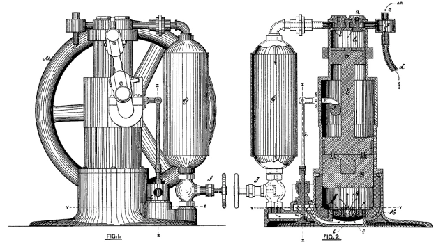
brayton-1872-patent-ready-motor-engine

Patent drawings of George Brayton’s 1872 engine. Gas and air was drawn into cylinder C, compressed by piston D, and stored in reservoir G. The mixture was then released into cylinder A and ignited as it passed through wire gauze e. As the mixture combusted and expanded, it acted on piston B.

Brayton was an inventor, engineer, and machinist who had experience with steam engines. Some of his internal combustion engine experiments date back to the early 1850s, but he began serious development around 1870. In 1872, Brayton patented a new type of engine, the first in a series that became known as the Brayton Ready Motor. The name “Ready Motor” described the fact that the engine was immediately ready for operation, unlike a steam engine. The Brayton engine was also called a “Hydro-Carbon Engine.” The engine used fuel (hydrocarbons) mixed with air as the working fluid that directly acted on the piston, rather than the fuel heating some other working fluid, as with a steam engine. The theoretical process by which the Brayton engine worked became known as the constant-pressure cycle or Brayton cycle. The Brayton cycle in a piston engine involves the pressure in the engine’s cylinder being maintained by the continued combustion of injected fuel as the piston moves down on its power stroke. The constant-pressure Brayton cycle is used in gas turbines and jet engines and is also very similar to the Diesel cycle.

Brayton’s 1872 patent engine was a two-stroke that had two pistons mounted to a common connecting rod. The smaller of the two pistons acted as an air pump, compressing the air to around 65 psi (4.5 bar). A gaseous fuel, such as illuminating gas or carbureted hydrogen, was mixed with the air entering the compression cylinder. Alternatively, an oil fuel, such as naphtha, could be vaporized and added to the air entering the compression cylinder. The air/fuel mixture was then compressed, passed through a valve, and stored in a reservoir. An engine-driven camshaft opened a valve that allowed the pressurized air/fuel mixture to flow from the reservoir and into the large combustion cylinder. Before entering the cylinder, the air/fuel mixture passed through layers of wire gauze where a small pilot flame constantly burned. The pilot flame was kept lit by a continuous, small supply of the air/fuel mixture. As the charge passed through the wire gauze and entered the cylinder, it was ignited by the pilot flame. The combusting and expanding gases created around 45 psi (4.1 bar) of pressure that forced the large piston back in its cylinder, creating the power stroke. At the same time, the small piston was moved toward top dead center in its cylinder, compressing another charge of air for continued operation.

brayton-1874-patent-ready-motor-engine

Brayton’s 1874 patent illustrating a double-sided piston. The upper side of piston B compressed air as the lower side was exposed to the combustion process of air and fuel being mixed and ignited in chamber H. Reservoir C only stored compressed air.

Brayton’s experience with steam engines and how steam expands into the cylinder to smoothly act on the piston probably influenced his desire to have the fuel burn in the cylinder. Gas expansion created by burning fuel acts smoothly on the piston, whereas the sudden ignition of fuel by a spark creates more of an explosion that exposes the piston and other engine components to high stresses. The combustion (motor) cylinder was about twice the volume of the compression (pump) cylinder, and the reservoir was no more than twice the volume of the combustion cylinder. The pressure in the reservoir was always greater than the pressure in the combustion cylinder. A water jacket surrounded the combustion cylinder to provide engine cooling.

While the 1872 patent illustrated an engine utilizing a separate compression piston, Brayton explained in the patent that the same principles of his engine could be applied utilizing both sides of the same piston. One side of the piston would compress the working fluid, while the other side of the piston would be driven by the expanding gases as the working fluid undergoes combustion. The patent drawing also shows a flywheel mounted to the camshaft. Engine power would be distributed from a driving pulley on the opposite end of the flywheel. However, images of early Brayton engines show an articulated rod mounted to the connecting rod that drove the flywheel and drive pulley.

brayton-vertical-ready-motor-engine

Brayton Ready Motor vertical engine with a double-sided piston. The air reservoir was housed in the rocking beam support column. Note the ball governor.

Around 1873, Brayton installed a 4 hp (3.0 kW) engine in a streetcar in Providence, Rhode Island. The streetcar could obtain a speed of 15 mph (24 km/h), but it would barely move with a full load and had difficulty climbing an incline. A larger 12 hp (8.9 kW) engine was substituted, as it was the most powerful Brayton engine that fit in the space available. The engine took up the space of one passenger and enabled the streetcar to climb a 5 percent grade. All total, the streetcar was tested for 18 months. However, the tests indicated issues with wheel slip on the rails, especially in snow or ice, and financial issues brought an end to the experiment.

A drawback to the 1872 engine was the storage of the volatile gas mixture in the reservoir. If any flame were to get past the wire gauze and continue to burn back to the reservoir, the contents of the reservoir would explode. A safety valve prevented damage to the engine, but such an event was very disconcerting to anyone near the engine. The use of light, gaseous fuel exacerbated the issue. In 1874, Brayton switched to a heavy petroleum oil fuel and patented a refined engine in which only air was stored in the reservoir. A small supply of petroleum fuel was pumped into absorbent, porous material contained in a chamber that surrounded the induction pipe. The top of the chamber formed what was basically a burner. As the liquid fuel was heated by the engine and vaporized, it joined with the air charge being admitted into the cylinder via a camshaft-driven valve. The mixture was then ignited as it flowed through the burner section and into the cylinder. The burner stayed lit by residual fuel from the absorbent material mixing with a small amount of air from the reservoir that constantly passed through the burner.

brayton-ready-motor-chart

Engine speed was controlled by an admission valve that regulated the amount of air passing into the cylinder. Although the fuel quantity supplied to the chamber was metered and dependent on engine speed, making changes to engine speed proved to be difficult. Any change in the amount of air supplied meant that there was a brief period of either too much or too little fuel, and this would occasionally extinguish the burner flame. By 1876, this issue had been resolved by implementing a new fuel injection process. The incoming air passed through the absorbent, porous material that was saturated with injected fuel. A jet of air coincided with the injection of fuel and helped distribute the fuel throughout the absorbent material. This injection technique proved more responsive than the earlier vaporization process.

Other changes incorporated in the 1874 engine were the use of both sides of the piston. A rod connected to the compression side of the piston extended out of the engine. The rod decreased the volume of the compression cylinder to less than that of the combustion cylinder. The rod also provided a means to harness power from the reciprocating movement of the piston. Although the rod was mounted on the compression side of the double-sided piston, it was the power stroke of the combustion side that provided the motive force.
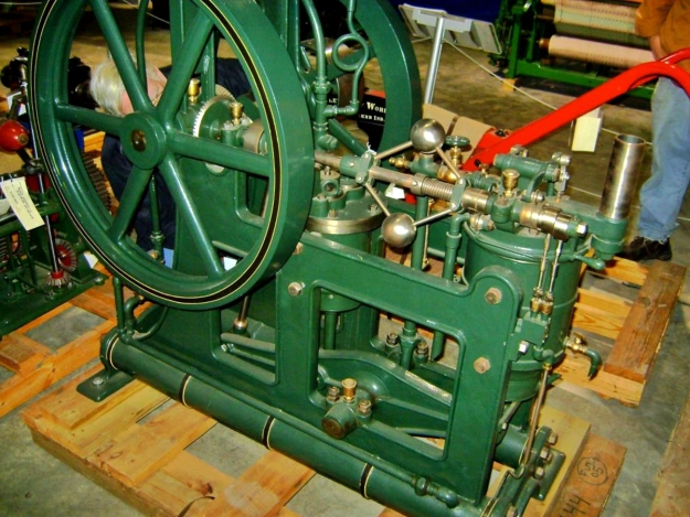
brayton-1876-inverted-walking-beam-engine

Circa 1876 Brayton inverted rocking beam engine. The combustion cylinder is on the left, and the smaller compression cylinder is at the center of the engine. Two air reservoirs made up the engine’s base; one was used for operating the engine, and the other was used for starting. The engine is currently in storage at the Smithsonian. (Woody Sins image via John Lucas / smokstak.com)

Development of the Brayton Ready Motor continued, and by 1875, the compression cylinder was completely separate from the combustion cylinder. Both cylinders had the same bore, but the stroke of the compression cylinder was about half that of the combustion cylinder. A number of different engine styles, both vertical and horizontal, were built, and the engines used different ways to harness the power of the compression cylinder. Some engines used the compression cylinder to actuate a rocking beam; other engines had the compression cylinder connected to a crankshaft that turned the power wheel.

By 1875 (and possibly as early as 1873), the Pennsylvania Ready Motor Company in Philadelphia had been established to sell Brayton’s engines, but the engines were built in the Exeter Machine Works in Exeter, New Hampshire. The Brayton Ready Motor may have been the first commercially available internal combustion engine. Engines based on the Brayton cycle were also sold by a number of other companies, including the New York & New Jersey Motor Company (by 1877) and Louis Simon & Sons, in Nottingham, England in 1878.
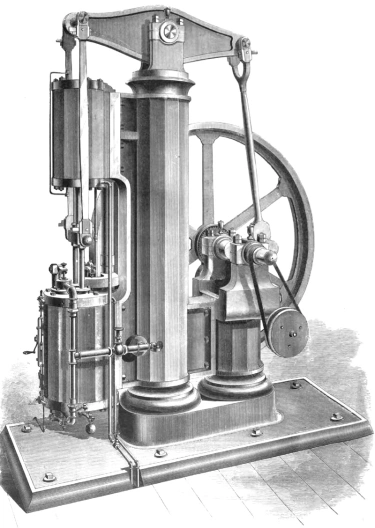
brayton-1876-vertical-engine

Drawing of the 10 hp (7.5 kW) vertical Brayton Ready Motor displayed at the Centennial Exposition in Philadelphia, Pennsylvania in 1876. This is the same engine that inspired George Selden. The compression cylinder was mounted above the combustion cylinder. The column supporting the rocking beam also contained the reservoir.

In 1878, John Holland used a 4 hp (3.0 kW) vertical Brayton engine in the first submarine powered by an internal combustion engine, the Holland I. While functional, this submarine was not a true success. Holland’s second submarine, the Fenian Ram, used a 15 hp (11.2 kW) horizontal Brayton engine and was launched in 1881. This submarine has been preserved and is displayed in the Paterson Museum in Paterson, New Jersey.

Also in 1878, a vertical engine was tested in an omnibus in Pittsburgh, Pennsylvania, but local authorities would not permit its use to transport passengers. Scottish engine pioneer Dugald Clerk converted a 5 hp (3.7 kW) Brayton engine to spark ignition. This engine was the first two-stroke, spark ignition engine ever built. Horizontal engines were installed in a few boats that operated on the Hudson River. In 1880, the USS Tallapoosa was fitted with a Brayton engine capable of 300 rpm. Other Brayton engines were used for industrial purposes such as powering pumps, cotton gins, or grinding mills. These Brayton engines were the first practical oil engines and were noted for their ease of starting and steady operation.
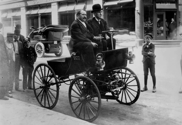
selden-auto-1906

George Selden and Ernest Samuel Partridge in the Selden automobile in 1905. The vehicle was built in 1903 to prove the viability of Selden’s patent design. Between the front wheels is a three-cylinder Brayton-style engine, which ultimately led to Selden’s patent claims being dismissed.

George Selden was inspired by the 10 hp (7.5 kW) Brayton engine he saw at the 1876 Centennial Exposition in Philadelphia and felt the engine could be adapted to power a practical wheeled vehicle (automobile). In 1879, Selden applied for a patent on his three-cylinder Road Engine, which powered a four-wheel carriage. Selden continued to delay his patent with minor modifications until 1895, when the patent was finally granted despite the fact that Selden had never built the actual vehicle. That did not deter Selden from claiming he invented the automobile and demanding royalties from all automobile manufactures—suing those who refused to pay. Henry Ford led the rebellion against Selden and lost the court case in 1909. However, that ruling was overturned on appeal in 1911. For the successful appeal, Ford demonstrated that Selden’s automobile used an engine based on the Brayton cycle (two-stroke and a constant-pressure cycle), while Ford and others used engines based on the design of Nicolaus Otto (Otto cycle: four-stroke and a constant-volume cycle). No automobiles were built with a Brayton cycle engine; therefore, the automobile manufacturers were not infringing on Selden’s patent.

By the late 1880s, it was becoming clear that the Brayton cycle for piston-driven internal combustion engines was outclassed by the more efficient Otto cycle. The main issue facing the Brayton engine was its relatively low pressure (60–80 psi / 4.1–5.5 bar) combined with excessive friction, pumping, and heat losses between the compression and combustion cylinders.

brayton-horizontal-marine-engine

Horizontal Brayton Ready Motor marine engine that was very similar, but not identical, to the engine used in the Fenian Ram submarine. The combustion cylinder is in the foreground, and the compression cylinder is in the background. The bevel gear powered the propeller shaft.

Brayton continued to develop his engine and applied for a patent in 1887 that outlined a horizontal, fuel injected, four-stroke engine. The cylinder was closed at both its combustion (hot) and non-combustion (cool) sides. Exhaust from the hot side of the cylinder passed through a water-cooled condenser that opened to the cool side of the cylinder. As the piston moved up on the exhaust stroke, the vacuum created in the cool side of the cylinder helped draw exhaust gases out of the hot side of the cylinder. An exhaust valve on the cool side of the cylinder was sprung to open at just above atmospheric pressure. As the piston moved toward the cool side of the cylinder on the intake stroke, the exhaust valve opened to expel the products of combustion. When the intake valve was opened, it brought fresh air into the cylinder and sealed the condenser. The intake valve then closed, and the piston moved toward the hot side of the cylinder to compress the air. Brayton stated in his patent that the cylinder’s cycle provided an abundance of fresh air to increase the engine’s power and efficiency.

Once the air was compressed, fuel was injected into the cylinder. The act of injecting the petroleum oil under pressure converted the fuel to a fine spray that was easily ignitable. The fuel injection pump was controlled by a follower riding on an engine-driven camshaft, and engine speed was controlled by the quantity of fuel injected. Once injected, the fuel was ignited by an incandescent burner made from a coil of platinum wire. This concept is very similar to a hot bulb in a much later semi-diesel engine. Brayton’s fuel injection was ideally suited for the use of heavy fuels. This engine was built with a 7 in (179 mm) bore and a 10 in (254 mm) stroke, displacing 385 cu in (6.31 L). Running at 200 rpm and driving a 30 in (762 mm) fan at 1,500 rpm for 10 hours, the engine only consumed 3.5 gallons (13.2 L) of kerosene.

brayton-1887-patent-ready-motor-engine

Patent drawing showing the cylinder of Brayton’s horizontal, four-stroke engine of 1887. Passage d was used for both intake and exhaust. Passage d1 harnessed the vacuum created under the piston to help draw the exhaust gases out of the cylinder and through the condenser (C). The exhaust was expelled via valve g1. Fresh air was admitted via valve e1, which sealed the condenser. Fuel was injected via “Oil-jet” F and ignited by a platinum coil.

In 1890, Brayton patented his last engine, a vertical four-stroke that featured fuel injection. As the piston moved down on its intake stroke, a valve in the piston head opened and allowed air from the crankcase to enter the vacuum in the cylinder. As the piston moved up on the compression stroke, the exhaust valve opened for a short time to evacuate any remaining products of combustion. With all valves closed, the remaining air was compressed, and fuel was injected in a combustion chamber space above the piston. A connecting rod attached the piston to an inverted rocking beam, and the opposite end of the rocking beam was connected to a crankshaft. A small air pump was driven from a rod connected to the rocking beam. The air pump provided the pressure for the fuel injection system, enabling a blast of air to disperse the fuel into a fine spray as it was forced into the combustion chamber. The fuel was ignited by an incandescent burner and continued to burn as more fuel was injected and the piston moved down on the power stroke. Brayton’s last engine worked through a similar process as the engines Rudolf Diesel began developing in 1893, but Diesel used much higher cylinder pressures.

While traveling in England and still experimenting with engines, Brayton passed in 1892 at the age of 62. Production of his engines had already decreased by the time of his death but may have continued until the early 1900s. While names like Otto and Diesel are known to many today, Brayton’s is relatively unknown despite his pioneering work. Brayton’s engines were used in land vehicles, boats, and submarines before Otto’s or Diesel’s engines successfully ran. Undoubtedly, Brayton’s engineering contributions helped pave the way for many who followed. Out of the hundreds of Brayton Ready Motors that were made, only around six original engines are known to survive today.
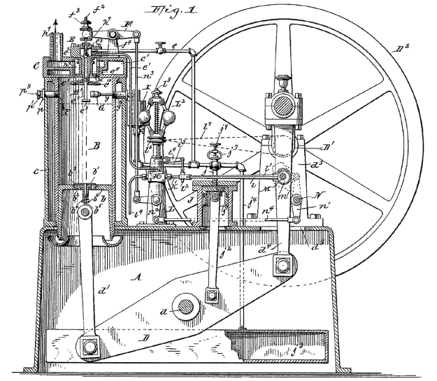
brayton-1890-patent-ready-motor-engine

Patent drawing illustrating Brayton’s 1890 inverted rocking beam (D) engine. Air slightly pressurized in the crankcase (A) passed through a valve (b1) in the piston to fill the cylinder (B). Fuel was injected (via g) and ignited by a burner (G) in a combustion chamber space (B1) at the top of the cylinder. A smaller cylinder (J) acted as a pump to power the fuel injector.

Sources:
– Correspondence with John Lucas
– “Improvement in Gas Engines” US patent 125,166 by George B. Brayton (granted 2 April 1872)
– “Gas Engines” US patent 151,468 by George B. Brayton (granted 2 June 1874)
– “Gas and Air Engine” US patent 432,114 by George B. Brayton (applied 15 September 1887)
– “Hydrocarbon Engine” US patent 432,260 by George B. Brayton (granted 15 July 1890)
Internal Fire by C. Lyle Cummins Jr. (1976/1989)
The Gas and Oil Engine by Dugald Clerk (1904)
A Text-Book on Gas, Oil, and Air Engines by Bryan Donkin Jr (1894)
Pioneers, Engineers, and Scoundrels by Beverley Rae Kimes (2005)
– “The Brayton Ready Motor or Hydrocarbon Engine” Scientific American (13 May 1876)
– “Brayton’s Hydrocarbon Engine” Scientific American Supplement, No. 58 (10 February 1877)
– “Selden Patent Not Infringed” The Automobile (12 January 1911)
– “Road Engine” US patent 549,160 by George B Selden (applied 8 May 1879)
– “Events Which Led Up to the Formation of the American Street Railway Association” by D. F. Longstreet The Street Railway Journal (November 1892)
http://todayinsci.com/B/Brayton_George/BraytonGeorgeBoat.htm
http://todayinsci.com/B/Brayton_George/BraytonGeorgeEngine.htm
http://todayinsci.com/B/Brayton_George/BraytonGeorgeEngine2.htm
http://todayinsci.com/B/Brayton_George/BraytonGeorge.htm
https://www.smokstak.com/forum/showthread.php?t=115633
http://users.zoominternet.net/~pcgray/FenianRam/fenianarticle.htm
http://vintagemachinery.org/mfgindex/imagedetail.aspx?id=6367

Zvezda M503 Rear

Yakovlev M-501 and Zvezda M503 and M504 Diesel Engines

By William Pearce

Just after World War II, OKB-500 (Opytno-Konstruktorskoye Byuro-500 or Experimental Design Bureau-500) in Tushino (now part of Moscow), Russia was tasked with building the M-224 engine. The M-224 was the Soviet version of the Junkers Jumo 224 diesel aircraft engine. Many German engineers had been extradited to work on the engine, but the head of OKB-500, Vladimir M. Yakovlev, favored another engine project, designated M-501.

Zvezda M503 front

Front view of a 42-cylinder Zvezda M503 on display at the Technik Museum in Speyer, Germany. Unfortunately, no photos of the Yakovlev M-501 have been found, but the M503 was very similar. Note the large, water-jacketed exhaust manifolds. The intake manifold is visible in the engine Vee closest to the camera. (Stahlkocher image via Wikimedia Commons)

Yakovlev and his team had started the M-501 design in 1946. Yakovlev felt the M-224 took resources away from his engine, and he was able to convince Soviet officials that the M-501 had greater potential. All development on the M-224 was stopped in mid-1948, and the resources were reallocated to the M-501 engine.

The Yakovlev M-501 was a large, water-cooled, diesel, four-stroke, aircraft engine. The 42-cylinder engine was an inline radial configuration consisting of seven cylinder banks positioned around an aluminum crankcase. The crankcase was made up of seven sections bolted together: a front section, five intermediate sections, and a rear accessory section. The crankshaft had six throws and was supported in the crankcase by seven main bearings of the roller type.

Each cylinder bank was made up of six cylinders and was attached to the crankcase by studs. The steel cylinder liners were pressed into the aluminum cylinder block. Each cylinder had two intake and two exhaust valves actuated via roller rockers by a single overhead camshaft. The camshaft for each cylinder bank was driven through bevel gears by a vertical shaft at the rear of the bank. All of the vertical shafts were driven by the crankshaft. The pistons for each row of cylinders were connected to the crankshaft by one master rod and six articulating rods.

Zvezda M503 Rear

Rear view of a M503 on display at Flugausstellung L.+P. Junior in Hermeskeil, Germany. The upper cylinder gives a good view of the exhaust (upper) and intake (lower) manifolds, and the engine’s intake screen can just be seen between the manifolds as they join the compounded turbosupercharger. The exhaust gases exited the top of the turbine housing. (Alf van Beem image via Wikimedia Commons)

Exhaust was taken from the left side of each cylinder bank and fed through a manifold positioned in the upper part of the Vee formed between the cylinder banks. The exhaust flowed through a turbosupercharger positioned at the extreme rear of the engine. Exhaust gases expelled from the turbosupercharger were used to provide 551 lbf (2.45 kN / 250 kg) of jet thrust.

The pressurized intake air from the turbosupercharger was fed into a supercharger positioned between the turbosupercharger and the engine. The single-speed supercharger was geared to the crankshaft via the engine’s accessory section. Air from the supercharger flowed into a separate intake manifold for each cylinder bank. The intake manifold was positioned in the lower part of the Vee, under the exhaust manifold, and connected to the right side of the cylinder bank.

The M-501 had a 6.30 in (160 mm) bore and a 6.69 in (170 mm) stroke. The engine displaced 8,760 cu in (143.6 L) and produced 4,750 hp (3,542 kW) without the turbosupercharger. With the turbosupercharger and the thrust it provided, the engine produced 6,205 hp (4,627 kW). The engine weighed 6,504 lb (2,950 kg) without the turbocharger and 7,496 lb (3,400 kg) with the turbocharger.

Zvezda M503 Bulgaria

This partially disassembled M503 at the Naval Museum in Varna, Bulgaria gives some insight to the inner workings of the engine. The turbine wheel can be seen on the far left. Immediately to the right is the air intake leading to the compressor wheel, which is just barely visible in its housing. From the compressor, the air was sent through the seven outlets to the cylinder banks. The exhaust pipe can just be seen inside the water-jacketed manifold on the upper cylinder bank. Note the studs used to hold the missing cylinder bank. (Михал Орела image via Wikimedia Commons)

By 1952, the M-501 had been completed and had achieved over 6,000 hp (4,474 kW) during tests. The program was cancelled in 1953, as jet and turbine engines were a better solution for large aircraft, and huge piston aircraft engines proved impractical. The M-501 was intended for the four-engine Tupolev 487 and Ilyushin IL-26 and was proposed for the six-engine Tupolev 489. None of these long-range strategic bombers progressed beyond the design phase.

The lack of aeronautical applications did not stop the M-501 engine. A marine version was developed and designated M-501M. The marine engine possessed the same basic characteristics as the aircraft engine, but the crankcase casting were made from steel rather than aluminum. The M-501M was also fitted with a power take off, reversing clutch, and water-jacketed exhaust manifolds.

The exact details of the M-501M’s history have not been found. It appears that Yakovlev was moved to Factory No. 174 (K.E. Voroshilov) to further develop the marine engine design. Factory No. 174 was founded in 1932 and was formerly part of Bolshevik Plant No. 232 (now the GOZ Obukhov Plant) in Leningrad (now St. Petersburg). Factory No. 174 had been involved with diesel marine engines since 1945, and Yakovlev’s move occurred around 1958. Early versions of the marine engine had numerous issues that resulted in frequent breakage. In the 1960s, the engine issues were resolved, and Factory No. 174 was renamed “Zvezda” after the engine’s layout. Many languages refer to radial engines as having a “star” configuration, and “zvezda” is “star” in Russian. Zvezda produced the refined and further developed 42-cylinder marine engine as the M503.

Zvezda M503 cross section

Sectional rear view of a 42-cylinder Zvezda M503. The cylinder banks were numbered clockwise starting with the lower left; bank three had the master connecting rod. Note the angle of the fuel injector in the cylinder and that the injector pumps were driven by the camshaft (as seen on the upper left bank).

The Zvezda M503 retained the M-501’s basic configuration. The engine had a compounded turbosupercharger system with the compressor wheel connected to the crankshaft via three fluid couplings. The compressor wheel shared the same shaft as the exhaust turbine wheel. At low rpm, the exhaust gases did not have the energy needed to power the turbine, so the compressor was powered by the crankshaft. At high rpm, the turbine would power the compressor and create 15.8 psi (1.09 bar) of boost. Excess power was fed back into the engine via the couplings connecting the compressor to the crankshaft. Air was drawn into the turbosupercharger via an inlet positioned between the compressor and turbine.

The M503’s bore, stroke, and displacement were the same as those of the M-501. Its compression ratio was 13 to 1. The M503’s maximum output was 3,943 hp (2,940 kW) at 2,200 rpm, and its maximum continuous output was 3,252 hp (2,425 kW) at the same rpm. The engine was 12.14 ft (3.70 m) long, 5.12 ft (1.56 m) in diameter, and had a dry weight of 12,015 lb (5,450 kg). The M503 had a fuel consumption of .372 lb/hp/h (226 g/kW/h) and a time between overhauls of 1,500 to 3,000 hours.

Zvezda M503 Dragon Fire

Dragon Fire’s heavily modified M503 engine under construction. Each cylinder bank is missing its fuel rail and three six-cylinder magnetos. The turbine wheel has been discarded. The large throttle body on the left has a single butterfly valve and leads to the supercharger compressor. Note that the cylinder barrels and head mounting studs are exposed and that each valve has its own port. (Sascha Mecking image via Building Dragon Fire Google Album Archive)

M503 engines were installed in Soviet Osa-class (Project 205) fast attack missile boats used by a number of countries. Each of these boats had three M503 engines installed. Engines were also installed in other ships. A heavily modified M503 engine is currently used in the German Tractor Pulling Team Dragon Fire. This engine has been converted to spark ignition and uses methanol fuel. Each cylinder has three spark plugs in custom-built cylinder heads. The engine also uses custom-built, exposed, cylinder barrels and a modified supercharger without the turbine. Dragon Fire’s engine produces around 10,000 hp (7,466 kW) at 2,500 rpm and weighs 7,055 lb (3,200 kg).

For more power, Zvezda built the M504 engine, which had seven banks of eight cylinders. Essentially, two additional cylinders were added to each bank of the M503 to create the 56-cylinder M504. The M504 did have a revised compounded turbosupercharging system; air was drawn in through ducts positioned between the engine and compressor. The intake and exhaust manifolds were also modified, and each intake manifold incorporated a built-in aftercooler. At full power, the turbosupercharger generated 20.1 psi (1.39 bar) of boost. The M504 engine displaced 11,681 cu in (191.4 L), produced a maximum output of 5,163 hp (3,850 kW) at 2,000 rpm, and produced a maximum continuous output of 4,928 hp (3,675 kW) at 2,000 rpm. The engine had a length of 14.44 ft (4.40 m), a diameter of 5.48 ft (1.67 m), and a weight of 15,983 lb (7,250 kg). The M504 had a fuel consumption of .368 lb/hp/h (224 g/kW/h) and a time between overhauls of 4,000 hours. The engine was also used in Osa-class missile boats and other ships.

Zvezda M504 56-cyl

The 56-cylinder Zvezda M504 engine’s architecture was very similar to that of the M503, but note the revised turbocharger arrangement. Wood covers have been inserted into the air intakes. Just to the right of the visible intakes are the aftercoolers incorporated into the intake manifolds.

In the 1970s, Zvezda developed a number of different 42- and 56-cylinder engines with the same 6.30 in (160 mm) bore, 6.69 in (170 mm) stroke, and basic configuration as the original Yakovlev M-501. Zvezda’s most powerful single engine was the 56-cylinder M517, which produced 6,370 hp (4,750 kW) at 2,000 rpm. The rest of the M517’s specifications are the same as those of the M504, except for fuel consumption and time between overhauls, which were .378 lb/hp/h (230 g/kW/h) and 2,500 hours.

Zvezda also coupled two 56-cylinder engines together front-to-front with a common gearbox in between to create the M507 (and others) engine. The engine sections could run independently of each other. The 112-cylinder M507 displaced 23,361 cu in (383 L), produced a maximum output of 10,453 hp (7,795 kW) at 2,000 rpm, and produced a maximum continuous output of 9,863 hp (7,355 kW) at the same rpm. The engine was 22.97 ft (7.00 m) long and weighed 37,699 lb (17,100 kg). The M507 had a fuel consumption of .378 lb/hp/h (230 g/kW/h) and a time between overhauls of 3,500 hours for the engines and 6,000 hours for the gearbox.

Zvezda engineer Boris Petrovich felt the 56-cylinder M504 engine could be developed to 7,000 hp (5,220 kW), and the M507 (two coupled M504s) could be developed to over 13,500 hp (10,067 kW). However, gas turbines were overtaking much of the diesel marine engine’s market share. Today, JSC (Joint Stock Company) Zvezda continues to produce, repair, and develop its line of M500 (or ChNSP 16/17) series inline radial engines as well as other engines for marine and industrial use.

Zvezda-M507-engine-korabel

The M507 was comprised of two M504 engines joined by a common gearbox. The engine sections had separate systems and were independent of each other. (www.korabel.ru image)

Sources:
Russian Piston Aero Engines by Vladimir Kotelnikov (2005)
Unflown Wings by Yefim Gordon and Sergey Komissarov (2013)
Ungewöhnliche Motoren by Stefan Zima and Reinhold Ficht (2010)
http://www.propulsionplant.ru/dvigateli/dizelnye-dvigateli/proizvodstvennoe-obedinenie-zvezda/dizeli-tipa-chn1617.html
https://de.wikipedia.org/wiki/Swesda_M503
http://www.zvezda.spb.ru
http://www.shipyard.lv/en/services/engineering/
http://lunohoda.net/forum/viewtopic.php?t=6067
http://www.competitiondiesel.com/forums/showthread.php?t=128242
https://en.wikipedia.org/wiki/Osa-class_missile_boat

1939 Venturi-Mora Saimon-Fiat

Idroscivolanti and the Raid Pavia-Venezia

By William Pearce

An airboat is a vessel that has a shallow draft and utilizes the thrust generated by an aircraft propeller to drive over ice, grass, or water. The airboat concept started as a way to test propellers but evolved into a nearly indispensable form of transportation though swampy areas. In Italy in the 1930s, the concept of an airboat was taken a bit further.

1930 Mazzotti-Cattaneo SIAI-IF

The Isotta Fraschini Asso 200-powered SIAI hydroplane that Franco Mazzotti and Guido Cattaneo drove to victory in the 1930 and 1931 Raid Pavia-Venezia.

First run in 1929, the Raid Pavia-Venezia was an inshore powerboat race of around 269 miles (433 km) held in June. The course distance varied slightly by year. Starting on the Ticino River in Pavia, Italy, the race transitioned to the River Po and then through canals, finally ending in Venice. Fuel stops were incorporated along the route. Various parts of the course had many turns, hidden sandbars, and tight passageways. The Raid Pavia-Venezia was the creation of Vincenzo Balsamo, an engineer, sailor, and head of the Gruppo Motonautico della Lega Navale di Milano (Powerboat Section of the Navy League of Milan), the group that organized the race. The 1929 race was completed in 11:26:23 at an average of 22.164 mph (35.670 km/h).

1932 Biseo-Bertoli SIAI-FIAT

Attilio Biseo and Gino Bertoli won the 1932 Raid Pavia-Venezia in this SIAI idroscivolante powered by a FIAT A50 engine. (image via Three Point Hydroplanes)

The 1930 race marked the start of combining powerful Italian aircraft engines with shallow-hulled hydroplanes to create the idroscivolante (airboat). Idroscivolanti (airboats) would not only increase straight line speeds, they would also allow the boats to travel over shallow sandbars without worry. Only one idroscivolante was entered in the 1930 race. It used an Isotta Fraschini (IF) Asso 200 engine that turned a four-blade, wooden propeller. The Asso 200 was a 200 hp (149 kW), water-cooled, inline-six engine. It was mounted in a pusher configuration to the rear of a shallow-hulled boat built by SIAI (Società Idrovolanti Alta Italia or Northern Italy Seaplane Company, also known as Savoia-Marchetti). Driven by Count Franco Mazzotti with co-driver Guido Cattaneo, the SIAI/IF idroscivolante won the race with a time of 8:10:35, averaging 31.462 mph (50.633 km/h). The second place finisher was nearly an hour behind the idroscivolante.

1934 Salom-Celli Celli-SPA

The Celli hydroplane powered by an SPA 6A engine in a pusher configuration. Aldo Salom and Dino Celli campaigned this boat in 1933 and 1934. (image via Three Point Hydroplanes)

Mazzotti and Cattaneo won the 1931 race again in the SIAI/IF idroscivolante with a time of 6:52:54 and averaging 38.309 mph (61.653 km/h). However, they had competition in the form of driver Count Theo Rossi and co-driver Alfredo Stracconi in a Passarin idroscivolante powered by a FIAT (Fabbrica Italiana Automobili Torino or Italian Automobile Factory Turin) A50 engine. The A50 was an air-cooled, seven-cylinder, radial engine that produced 105 hp (78 kW). Rossi and Stracconi finished the race in second place at 33.648 mph (54.151 km/h).

Rossi and Stracconi were back in their Passarin/FIAT in 1932, but they were unable to complete the race. The only other idroscivolante was a SIAI powered by a FIAT and driven by Attilio Biseo and Gino Bertoli. The FIAT A50 radial engine was mounted in a tractor configuration on struts in the middle of the boat. Biseo and Bertoli won the 1932 race in 5:27:26 at a 47.138 mph (75.862 km/h) average speed. Biseo and Bertoli finished the Raid Pavia-Venezia 2:30:01 before the first conventional powerboat.

1934 Rossi-Cattaneo SIAI-IF

Theo Rossi and Guido Cattaneo paired up to compete in the Raid Pavia-Veneziain in this SIAI idroscivolante powered by an IF Asso 200 engine. This photo was most likely taken in 1934. (image via Three Point Hydroplanes)

For 1933, Theo Rossi and Guido Cattaneo joined forces in the SIAI/IF. The SIAI/FIAT idroscivolante was entered by driver Marcello Visconti di Modrone and co-driver Franco Mazzotti, but it did not finish the race. Rossi and Cattaneo took the win with a time of 6:37:14, averaging 40.639 mph (65.402 km/h) over the whole course. The pair averaged 56.511 mph (90.946 km/h) over the 37 miles (60 km) between Piacenza and Cremona.

In 1934, two of the three idroscivolanti entered in the race failed to finish. One of the non-finishers was a new, small SIAI hydroplane raced by Rossi and Cattaneo. It was powered by a 200 hp (149 kW) IF Asso 200 inline-six engine in a tractor configuration and housed in a streamlined cowling; the engine and propeller were probably from the previous SIAI/IF boat. The other idroscivolante that did not finish was a Celli hydroplane powered by a SPA (Società Ligure Piemontese Automobili or Ligure Piemontese Automobile Company) 6A engine and raced by Aldo Salom and Dino Celli. Their 205 hp (153 kW) inline-six engine was mounted at the rear of the boat in a pusher configuration and turned a four-blade, wooden propeller. The race was won by driver Attilio Biseo with co-driver Renato Donati in a SIAI hydroplane powered by a Farina T.58 135 hp (101 kW), air-cooled, five-cylinder, radial engine. The engine turned a two-blade propeller and was mounted in a tractor position at the middle of the boat. Their time was 5:44:08 with an average of 47.188 mph (75.942 km/h).

1934 Biseo-Donati SIAI-Farina

Attilio Biseo and Renato Donati competing in the 1934 race, which they won. Their SIAI idroscivolante was powered by a Farina T.58 engine. (image via Three Point Hydroplanes)

Four idroscivolanti competed in the 1935 Raid Pavia-Venezia. Driver Renato Donati and co-driver Federico Borromeo finished in sixth place overall. Their sleek, two-hulled, catamaran idroscivolante was designed by the Laboratorio Sperimentale Regia Aeronautica (Royal Italian Air Force Experimental Laboratory) but was most likely built by SIAI. It was powered by an air-cooled, seven-cylinder, 200 hp (149 kW) Alfa Romeo Lynx radial engine based on the Armstrong Siddeley Lynx and produced under license. The engine turned a three-blade, metal propeller and was mounted in a tractor configuration in the middle of the idroscivolante. In fourth place overall were Aldo Salom and Dino Celli in the Celli/SPA. In second place were driver Goffredo Gorini and co-driver Francesco Bertoli in the sister ship of Donati and Borromeo. However, their idroscivolante did not have a deck connecting the two hulls. Gorini and Bertoli finished the race in 5:12:30 and averaged 51.652 mph (83.126 km/h). The winners of the 1935 race were Rossi and Cattaneo in the SIAI/IF. Their boat had been modified with larger fuel tanks that bulged out above the two-hulls. Rossi and Cattaneo completed the race in 5:01:50 at 53.483 mph (86.073 km/h). They averaged 69.326 mph (111.570 km/h) over the 37 miles (60 km) from Piacenza to Cremona.

1935 Donati-Borromeo LSAR-AR

Renato Donati and Federico Borromeo in the Laboratorio Sperimentale Regia Aeronautica powered by an Alfa Romeo Lynx in 1935. Note the deck connecting the hulls. The idroscivolante sits in Venice’s Grand Canal with the Santa Maria della Salute in the background. (image via Three Point Hydroplanes)

Theo Rossi and Guido Cattaneo took another win in their SIAI/IF for 1936. Their time was 4:45:02 at an average speed of 56.576 mph (91.051 km/h), and they finished over three hours before the first conventional powerboat. Second place was won by Vito Mussolini and Carlo Maurizio Ruspoli in the SIAI/Farina. Vito Mussolini was Benito Mussolini’s nephew, and Carlo Maurizio Ruspoli was a Prince of Poggio Suasa. The third and last idroscivolante entered in the 1936 race was the Laboratorio Sperimentale Regia Aeronautica/Alfa Romeo of Goffredo Gorini and Renato Donati. While they did not finish the race, they did average 74.191 mph (119.400 km/h) over the 43 miles (69 km) between Pavia and Piacenz.

A race was also run on the Danube River between Vienna and Budapest in 1936. Which idroscivolanti participated and the results of the race have not been found. It can be assumed that the SIAI/IF idroscivolante raced by Rossi and Cattaneo did participate in this race, as it had “Vienna-Budapest” painted on its hull during the Pavia-Venezia race. At around 177 miles (285 km), the Vienna-Budapest race was about two-thirds the distance of the Raid Pavia-Venezia.

1935 Gorini-Bertoli LSAR-AR

The other Laboratorio Sperimentale Regia Aeronautica/Alfa Romeo driven by Goffredo Gorini and Francesco Bertoli in the 1935 Raid Pavia-Venezia. (image via Three Point Hydroplanes)

In 1937, driver Goffredo Gorini and co-driver Renato Donati won the race. Their idroscivolante was referred to as an SIAI, replacing Laboratorio Sperimentale Regia Aeronautica. The boat was still powered by an Alfa Romeo Lynx, but the engine struts and supports had been redesigned. In addition, a wide cord, two-blade, metal propeller was used. Gorini and Donati’s winning time was 4:47:32 with an average speed of 56.143 mph (90.354 km/h). In the sister ship, Prospero Freri and Salvatore Flamini took second place just 10 minutes behind the leader, with an average speed of 54.175 mph (87.186 km/h). Their idroscivolante was referred to as a CNA (Compagnia Nazionale Aeronautica or National Aeronautical Company), replacing Laboratorio Sperimentale Regia Aeronautica. The catamaran had new engine struts that now supported a nine-cylinder, 240 hp (179 kW) Alfa Romeo D.2 engine turning a three-blade, metal propeller. A Townend ring intended to reduce drag and improve engine cooling encircled the D.2’s cylinders. Theo Rossi and Guido Cattaneo, the previous year’s winners, placed third in their SIAI/IF.

1936 Rossi-Cattaneo SIAI-IF

Theo Rossi and Guido Cattaneo won the 1936 race in the SIAI/IF idroscivolante. Note the increased capacity fuel tanks that bulged above the deck and that “Budapest” is written on the hull. (image via Three Point Hydroplanes)

1938 saw five idroscivolanti entered in the Raid Pavia-Venezia race. Goffredo Gorini and Marco Ponzalino won the race in a SIAI/Alfa Romeo at a very fast time of 4:11:28, averaging 64.193 mph (103.308 km/h). Prospero Freri and Salvatore Flamini in the CNA/Alfa Romeo finished in second place. Vito Mussolini and Luciano Agosti took third place in the SIAI/Farina. Marco Celli and Aldo Tassinari finished in eighth place overall in a Celli catamaran powered by a 115 hp (86 kW) Walter Venus engine. On this boat, the seven-cylinder radial engine turned a three-blade propeller and was strut-mounted in a tractor configuration on the rear half of the catamaran. The last idroscivolante finished in ninth place overall; it was Aldo Salom and Bruno Rocca in a Celli hydroplane powered by an IF Asso 200 inline-six engine. The engine turned a four-blade, wooden propeller and was rear-mounted in a pusher configuration. Theo Rossi and Guido Cattaneo did not finish in their SIAI/IF.

1936 Mussolini Ruspoli SIAI-Farina

Vito Mussolini and Carlo Maurizio Ruspoli competing in the 1936 Raid Pavia-Venezia in the SIAI/Farina idroscivolante. (image via Three Point Hydroplanes)

In 1939, Goffredo Gorini and Marco Ponzalino won the Raid Pavia-Venezia again at a slightly slower pace than the previous year. They finished in 4:19:16 at an average speed of 62.264 mph (100.205 km/h). The pair averaged 79.477 mph (127.80 km/h) over the 43 miles (69 km) from Pavia to Piacenz and finished the race 3:32:44 before the first conventional powerboat. Sources list their idroscivolante as a Gorini powered by an Alfa Romeo engine. However, film taken during a speed run in August shows a catamaran very similar to the one used the previous year but powered by a Wright R-975 Whirlwind 330 hp (246 kW), nine-cylinder, radial engine that turned a two-blade, metal propeller. Finishing twenty-three minutes behind them was their sister ship, listed as a Gorini/Freri/Alfa Romeo. Driver Prospero Freri and co-driver Salvatore Flamini averaged 57.148 mph (91.970 km/h). Freri and Flamini’s idroscivolante no longer had a Townend ring around the engine; the Alfa Romeo D.2’s cylinders were exposed to the air. In addition, a two-blade, metal propeller was installed. Fernando Venturi and Paolo Mora finished third in a Saliman (some sources say Saimon) catamaran powered by a FIAT A50 engine. The engine of this two-hulled idroscivolante was mounted in a tractor configuration at the center of the boat and turned a two-blade, wooden propeller. The SIAI/Farina idroscivolante of Vito Mussolini and Luciano Agosti finished in fourth place.

1937 Gorini-Donati LSAR-AR

Goffredo Gorini and Renato Donati won the 1937 race in the SIAI/Alfa Romeo idroscivolante. Note the wide cord, two-blade propeller on the Lynx engine.

In July 1939, Fernando Venturi in the Saliman/FIAT idroscivolante set an 800 kg (1,764 lb) class speed record of 49.692 mph (79.971 km/h) on Lake Bracciano. The record was broken in August when Goffredo Gorini achieved 91 mph (147 km/h) in the Wright Whirlwind-powered Gorini idroscivolante mentioned earlier. This appears to be a new idroscivolante, as the Alfa Romeo Lynx-powered machine was also present for the speed runs. Gorini had reached 96 mph (155 km/h), but technical difficulties prevented him from maintaining that speed. Gorini’s Wright-powered idroscivolante still had “Raid-Pavia-Venezia” painted on the hull from the race two months earlier.

1938 Freri-Flamini CNA-AR

For the 1937 Raid Pavia-Venezia, Prospero Freri and Salvatore Flamini installed a nine-cylinder Alfa Romeo D.2 engine with a three-blade propeller and a Townend ring. The pair took second place in 1937, 1938, and 1939. This photo is from the 1938 race.

The Raid Pavia-Venezia was suspended in 1940 due to World War II. The race was held again in 1952, but the idroscivolanti were no longer allowed to compete. The 1952 and 1953 winners were slower than the idroscivolanti of the 1930s, but technology progressed quickly, and conventional powerboats soon outpaced the idroscivolanti. The large, powerful aircraft engines allowed the idroscivolanti to reach high speeds, but with limited fuel on board the sleek machines, more frequent fuel stops were required. Only around 12 idroscivolanti were built, but their type won all ten of the Raid Pavia-Venezia in which they participated, outpacing conventional powerboats by more than three hours over the 269 mile (433 km) course.

1939 Venturi-Mora Saimon-Fiat

Fernando Venturi and Paolo Mora’s FIAT-powerd Saliman in 1939. The idroscivolante finished the race in third place and went on to set a short-lived speed record of 49.692 mph (79.971 km/h) in July 1939. Santa Maria della Presentazione (Le Zitelle) is in the background. (image via Three Point Hydroplanes)

In August 1951, Franco Venturi, Fernando’s son, set an 800 kg (1,764 lb) class speed record of 97 mph (156 km/h) on Lake Sabaudia. The idroscivolante used for this record run was the same two-hulled catamaran used by Goffredo Gorini in 1939 to win the Raid Pavia-Venezia and establish an 800 kg speed record. However, the idroscivolante was modified with a three-blade, metal propeller attached to the Wright R-975 Whirlwind engine. With idroscivolanti banned from the Raid Pavia-Venezia, Franco Venturi eventually donated the machine to the Museo della Scienza e della Tecnologia “Leonardo da Vinci” (Museum of Science and Technology “Leonardo da Vinci”) in Milan, Italy, where it is currently preserved.

1951 Franco Venturi Gorini-Wright

The Gorini/Wright idroscivolante used to set a speed record in 1939 by Goffredo Gorini at 91 mph (147 km/h) and in 1951 by Franco Venturi at 97 mph (156 km/h). (image via Museo della Scienza e della Tecnologia)

Prospero Freri managed to save the idroscivolante that he drove to second place finishes in 1937, 1938, and 1939. Numbered 108 and later T-108, the racer had deteriorated over the years. After Freri passed away in 1965, his heirs donated T-108 to the Civico Museo Navale Didattico di Milano (Civic Museum of Naval Education of Milan) in 1967. In 2006, T-108 underwent a seven month restoration by the Dalla Pietà boatyard in Malcontenta. At the beginning of the restoration, T-108 had “XII Raid Pavia-Venezia” painted on the hull, indicating Freri had prepared the idroscivolante for the 1940 race (the 12th Raid Pavia-Venezia). After the restoration, the hull was painted “XI Raid Pavia-Venezia” (indicating the 1939 race) to eliminate any confusion. T-108 is currently on display in the Museo della Scienza e della Tecnologia “Leonardo da Vinci”.

Sadly, there is very little information on the idroscivolanti, and what information can be found is occasionally contradictory. The timeline in this article was developed by cross referencing existing information with contemporary photos and videos. While every effort was made to maintain accuracy, there is no guarantee the article is entirely correct. Most of material for this article came from Three Point Hydroplanes, a historical archive of Italian hydroplanes.

2007 T-108 Freri SIAI-AR

The Alfa Romeo D.2-powered idroscivolante driven by Prospero Freri and Salvatore Flamini to second place in the 1937, 1938, and 1939 races. It was restored to its 1939 Raid Pavia-Venezia configuration in 2007. (image via Dalla Pietà Yatch)

Idroscivolanti results in the Raid Pavia-Venezia

1930
1) Franco Mazzotti and Guido Cattaneo in the SIAI/Isotta Fraschini
8:10:35 averaging 31.462 mph (50.633 km/h)

1931
1) Franco Mazzotti and Guido Cattaneo in the SIAI/Isotta Fraschini
6:52:54 averaging 38.309 mph (61.653 km/h)
2) Theo Rossi and Alfredo Stracconi in the Passarin/FIAT
7:38:43 averaging 33.648 mph (54.151 km/h)

1932
1) Attilio Biseo and Gino Bertoli in the SIAI/FIAT
5:27:26 at 47.138 mph (75.862 km/h)
DNF) Theo Rossi and Alfredo Stracconi in the Passarin/FIAT

1933
1) Theo Rossi and Guido Cattaneo in the SIAI/Isotta Fraschini
6:37:14 averaging 40.639 mph (65.402 km/h)
DNF) Marcello Visconti di Modrone and Franco Mazzotti in the SIAI/FIAT

1934
1) Attilio Biseo and Renato Donati in the SIAI/Farina
5:44:08 averaging 47.188 mph (75.942 km/h)
DNF) Theo Rossi and Guido Cattaneo in the SIAI/Isotta Fraschini
DNF) Aldo Salom and Dino Celli in the Celli/SPA

1935
1) Theo Rossi and Guido Cattaneo in the SIAI/Isotta Fraschini
5:01:50 averaging 53.483 mph (86.073 km/h)
2) Goffredo Gorini and Francesco Bertoli in the Laboratorio Sperimentale Regia Aeronautica/Alfa Romeo
5:12:30 averaging 51.652 mph (83.126 km/h)
4) Aldo Salom and Dino Celli in the Celli/SPA
6:26:18 averaging 41.789 mph (67.253 km/h)
6) Renato Donati and Federico Borromeo in the Laboratorio Sperimentale Regia Aeronautica/Alfa Romeo
7:20:28 averaging 36.650 mph (58.982 km/h)

1936
1) Theo Rossi and Guido Cattaneo in the SIAI/Isotta Fraschini
4:45:02 averaging 56.576 mph (91.051 km/h)
2) Vito Mussolini and Carlo Maurizio Ruspoli in the SIAI/Farina
5:29:02 averaging 44.967 mph (72.367 km/h)
DNF) Goffredo Gorini and Renato Donati in the Laboratorio Sperimentale Regia Aeronautica/Alfa Romeo

1937
1) Goffredo Gorini and Renato Donati in the SIAI/Alfa Romeo
4:47:32 averaging 56.143 mph (90.354 km/h)
2) Prospero Freri and Salvatore Flamini in the CNA/Alfa Romeo
4:57:59 averaging 54.175 mph (87.186 km/h)
3) Theo Rossi and Guido Cattaneo in the SIAI/Isotta Fraschini
5:29:22 averaging 49.013 mph (78.878 km/h)

1938
1) Goffredo Gorini and Marco Ponzalino in the SIAI/Alfa Romeo
4:11:28 averaging 64.193 mph (103.308 km/h)
2) Prospero Freri and Salvatore Flamini in the CNA/Alfa Romeo
5:34:40 averaging 48.236 mph (77.629 km/h)
3) Vito Mussolini and Luciano Agosti in the SIAI/Farina
6:37:32 at 40.614 mph (65.352 km/h)
8) Marco Celli and Aldo Tassinari in the Celli/Walter
8:13:11 averaging 32.733 mph (52.678 km/h)
9) Aldo Salom and Bruno Rocca in the Celli/Isotta Fraschini
9:25:44 averaging 28.535 mph (45.922 km/h)
DNF) Theo Rossi and Guido Cattaneo in the SIAI/Isotta Fraschini

1939
1) Goffredo Gorini and Marco Ponzalino in the Gorini/Wright
4:19:16 averaging 62.264 mph (100.205 km/h)
2) Prospero Freri and Salvatore Flamini in the Gorini/Freri/Alfa Romeo
4:42.29 averaging 57.148 mph (91.970 km/h)
3) Fernando Venturi and Paolo Mora in the Saliman/FIAT
6:10:54 averaging 43.524 mph (70.045 km/h)
4) Vito Mussolini and Luciano Agosti in the SIAI/Farina
6:16:13 averaging 42.915 mph (69.065 km/h)

Sources:
http://www.threepointhydroplanes.it/raid-pavia-venezia_r1_en.htm (and numerous pages, images, and videos therein)
http://www.museoscienza.org/museo/patrimonio/idroscivolanteT108.asp
http://www.museoscienza.org/dipartimenti/catalogo_collezioni/scheda_oggetto.asp?idk_in=ST120-00498
http://www.pionieredellanautica.it/index.php?option=com_content&view=article&id=47&Itemid=55
Fernando Venturi 1939 Record Run (YouTube)
Geoffredo Gorini 1939 Record Run (YouTube)
Franco Venturi 1951 Record Run (YouTube)
Aerosphere 1939 by Glenn D. Angle (1940)
Aeronuatica Militare Museo Storico Catalogo Motori by Oscar Marchi (1980)

GM EM 16-184 x section

General Motors / Electro-Motive 16-184 Diesel Engine

By William Pearce

GM EM 16-184 maintenance

This image shows an Electro-Motive-built 16-184A engine (since the triangular access ports have flanges around them). The top of the cylinder barrels, each with four exhaust valves, can be seen in the middle cylinder bank. The engine’s coolant manifolds are still in place. Note the two water pumps.

In 1937, the United States Navy visited the General Motors Research Laboratories (GMRL) in Detroit, Michigan. Since 1934, GMRL had been involved in experimental, single-cylinder testing of a new light-weight diesel engine. The Navy was interested in a light and powerful diesel and contracted GMRL to develop an engine that would produce 1,200 hp (895 kW). With an output of around 75 hp (56 kW) per cylinder, an engine with 16 cylinders would be needed. However, a V-16 would be too long and too heavy. Led by Charles Kettering, the GMRL designed the unique 16-184 engine to meet the Navy’s needs. The 16-184 engine designation stood for 16 cylinders, with each displacing 184 cu in (3.0 L).

The two-stroke 16-184 diesel had four banks of four cylinders situated at 90 degrees around the crankshaft. A unique feature of the engine was its vertical configuration in which the rows of cylinders were stacked above one another. Because of the stacked cylinder arrangement, this engine configuration was called a “pancake.” A centrifugal blower to feed air into the cylinders sat on top of the engine, and the engine was mounted on top of its right angle gear reduction for the propeller shaft. The 2 to 1 gear reduction was achieved by a pinion on the end of the crankshaft engaging a ring gear mounted on the propeller shaft. No reversing gear was incorporated, because the engine was used in conjunction with variable-pitch propellers.

The 16-184’s crankcase was constructed of steel plates welded together to form a single structure. It was built-up of four “X” elements, each consisting of four cylinders. A static strength report on two of the crankcases noted that they were “…truly remarkable pieces of engineering, and they will well repay careful study by anyone whose work involves mechanical design, welding design, welding techniques and weight saving.

GM 16-184 crankcase

This image of a General Motors 16-184 crankcase undergoing a stress test reveals many unique aspects of the engine. An exhaust housing has been installed on the upper cylinder bank. The top of the engine is on the left side. The intake passageway can be seen in the upper Vee. The camshaft housing can be seen in the lower Vee. The cylinder liners are not installed. Note that the triangular access ports do not have flanges, making this a General Motors-built crankcase.

The crankshaft was supported in and attached to the crankcase by four main bearing carriers and the timing gear housing at the top of the engine. The connecting rods were of the slipper type, which allowed for equal articulation for each cylinder’s rod and reduced the load on the individual crankpins. Each forged-steel piston was attached to its connecting rod by two trunnions positioned on either side of the connecting rod and bolted to the piston.

The blower on the top of the engine fed air into two crankcase passageways on opposite sides of the engine. The blower spun at ten times crankshaft speed and delivered around 4,000 cu ft (113.27 cu m) of air per minute at 6 psi (0.4 bar). The air flowed through ports in each cylinder barrel that were uncovered by the piston. The top of the cylinder barrel was enclosed by a housing for the fuel injector (at center) and four exhaust valves (surrounding the fuel injector). This housing made up the cylinder’s combustion chamber. The exhaust valves opened into a space above the cylinders where exhaust flowed into an exhaust manifold. The exhaust manifold was positioned in the engine’s Vee and above the intake passageway. The cylinders used uniflow scavenging, in which fresh air would flow through the intake ports in the lower cylinder barrel and push the exhaust gases out the open valves at the top of the cylinder.

GM EM 16-184 x section

A sectioned view of one of the 16-184 X cylinder groups. The propeller shaft drive is at the top of the image. Note the camshaft in the upper and lower Vees. The dark areas in the left and right Vees are the intake air passageways. The cylinder ports can be seen in the lower left cylinder.

Two camshafts were geared to the crankshaft via an idler gear in the timing gear housing at the top of the engine. One camshaft was situated in each non-intake/exhaust engine Vee. The camshafts controlled three pushrods for each cylinder via roller cam followers. One pushrod controlled the fuel injector while the other pushrods each controlled two exhaust valves. The pushrods articulated rocker arms that were bolted to the top of a cast iron exhaust housing attached over each cylinder bank. The top of the cylinder barrel assembly passed through the exhaust housing. This configuration allowed exhaust gases from the cylinder to be collected by the exhaust housing and delivered to the exhaust manifold via three ports for each cylinder.

Each piston was cooled by a jet of oil impinging on its underside. Two centrifugal water pumps were driven by the lower accessory section. The upper pump circulated coolant through each exhaust housing. The upper part of the cylinder barrel had a welded sheet metal water jacket. Via a special connection, coolant flowed from the exhaust housing into the cylinder barrel water jacket. The lower pump circulated sea water through the jacketed exhaust manifolds.

The 16-184 engine had a 6.0 in (152 mm) bore and 6.5 in (165 mm) stroke, giving a total displacement of 2,941 cu in (48.2 L). The complete engine was roughly 11 ft (3.4 m) tall, 4 ft (1.2 m) wide, and weighed 4,800 lb (2,177 kg). The 16-184 developed 1,200 hp (895 kW) at 1,800 rpm.

GM EM 16-184 installed

This view of an installed 16-184A engine shows the three pushrods for each cylinder. The middle pushrod controlled the fuel injector. Note the pedal and lever in the Vee. The pedal engaged a clutch and the lever connected the engine to or disconnected the engine from the propeller shaft.

By 1938, single cylinder test engines were operating reliably and achieving the design goals necessary for a complete, 1,200 hp (895 kW) engine. The design for the complete 16-cylinder engine had been completed and prototype construction was underway. The 16-184 was first run in June 1939, and it completed the Navy’s 168-hour endurance test on 31 October 1940. In 1941, two test engines were installed in an experimental submarine chaser: USS PC-453 designed by Captain A. Loring Swasey. PC-453 served as the prototype for a class of wooden submarine chasers during World War II. The boat was re-designated SC-453 and transferred to the Coast Guard after the war.

In 1941, 16-184 engine production was undertaken by the Electro-Motive Division of General Motors. Electro-Motive originally produced railcars and was purchased by General Motors in 1930 as the latter looked to expand into the diesel engine and rail marketplaces. The production engines built by Electro-Motive were designated 16-184A and had some minor changes to their crankcases, including welded-in cylinder liners where the prototype’s were screwed-in. In addition, triangular access ports on the General Motors 16-184 crankcase did not have flanges, while the Electro-Motive 16-184A crankcase did. The Electro-Motive 16-184A engines were built in La Grange, Illinois, and the first engine started test runs on 11 October 1941. The Navy accepted the first 16-184A engine on 5 February 1942.

Two pancake engines were installed in each of the 253 110-foot (33.5 m) submarine chasers built during World War II. After the war, several of these boats were sold to other nations. The 16-184A engines were noted for their reliable operation and good service life. Some of these engines continued to operate (occasionally) into the year 2000. Approximately 544 16-184A engines were built.

GM 16-338

This image shows the intake side of the General Motors 16-338 engine installed on its generating unit. This arrangement led to issues, for any liquids that leaked from the engine would drain down into the generator.

The 16-184A engine design was used as the basis for the General Motors 16-338 engine built in the late 1940s. The 16-338 had the same bore and stroke as the 16-184A and produced 1,000 hp (746 kW) at 1,600 rpm. Four 16-338 engines were installed in the Tench- and Tang-class submarines, and two were installed in the USS Albacore—the Navy’s first “teardrop” hull submarine, which paved the way for modern sub design.

The 16-338 engines sat atop a generator to provide power to electric motors that drove the ship’s propellers. The engine also had a different intake and exhaust arrangement in which the manifolds were situated in separate Vees of the engine. The 16-338 engines proved somewhat unreliable in service and required excessive maintenance. Some of the 16-338’s issues were due to the Navy using standard diesel lubricating oil rather than the special oil specified for use in the engine. Ultimately, the Tench- and Tang-class submarines were re-engined and their 16-338 parts were used as spares to keep the USS Albacore running until it was withdrawn from service in 1972.

Sources:
– “Development of a Light Weight Diesel Engine” by J. C. Fetters, Diesel Power & Diesel Transportation (August 1942)
Parts Book GM Diesel Engine, Model 16-184A by Electro-Motive Division (1944)
Static Strength Tests of Diesel Engine Crankcases GMC 16-184 and EMC 16-184-A for 110-Foot Patrol Boats by J. W. Day (August 1943)
Diesel War Power by Electro-Motive Division, General Motors (1944)
Engines Afloat Volume II by Stan Grayson (1999)
http://usautoindustryworldwartwo.com/General%20Motors/electro-motive.htm
http://en.wikipedia.org/wiki/Electro-Motive_Diesel
http://www.navsource.org/archives/12/150453.htm
http://www.ss563.org/t-class.html
http://nonplused.org/panos/uss_albacore/12/engine_01.html

Michel 3-cylinder

Michel Opposed-Piston Diesel Engines

By William Pearce

Hermann Michel* of Voorde, Germany was a foreman at the Krupp Germania shipyard in Kiel, Germany. Through his work, he experienced the common problems of two-stroke submarine engines. Seeking to avoid the disadvantages of conventional engines, Michel designed a unique, new engine. He believed his engine would be particularly well suited for marine use. His design was for an opposed-piston, two-stroke, diesel engine. Beyond the use of opposed pistons, the Michel engine was unique in that it was a crankless cam engine. With minor changes in the basic engine design, the cylinder group could either be stationary or rotate like a rotary engine.  Michel filed a patent application for his engine configuration in Germany on 20 July 1920 and in the United States on 23 August 1921.

Michel Cam engines

Drawings from Hermann Michel’s original patent show two- and three-cylinder cam engines. In the drawings, the cylinder group was stationary and the cam ring rotated. The upper cylinder in the three-cylinder engine drawing had the exhaust ports. Note that it was angled slightly different than the other cylinders to facilitate scavenging.

Michel’s engine design was for either two pistons in a common cylinder or three pistons in three cylinders. Regardless of the number of pistons used, the cylinder group possessed a common combustion chamber in which the pistons moved toward each other on the compression stroke. The movement of opposite pistons covered or uncovered intake and exhaust ports that were in the cylinder walls. This configuration eliminated the use of valves and a head gasket. The intake and exhaust port locations allowed scavenging air to flow through the cylinder and completely evacuate any exhaust gases when the ports were open.

The engine did not have a crankshaft. The pistons’ movement was controlled by a comparatively large cam ring that surrounded the cylinder group. The rod for each piston had rollers in an annular cam track that formed an undulating path. This path determined the pistons’ movement in the cylinder and facilitated the compression stroke. When configured with stationary cylinders, the cam ring rotated around the cylinder group. For a rotary configuration, the cylinder group rotated inside the stationary cam ring.

Unlike a crankshaft that is directly tied to the cycle of the engine, the cam ring could be made with several compression and power cycles for each revolution. For example, if the cam ring had six cycles, the cylinder group would go through six compression and six power strokes for each revolution of the cam ring. Likewise on a rotary configuration, the cylinder group would go through six compression and six power strokes each revolution.

Michel cam rings

This Michel patent drawing from 1923 illustrates the axillary cam (21) and axillary piston rod rollers (20) on a two-cylinder opposed-piston engine. The main roller (7) rode on the main cam track (15).

Michel took out at least five other patents relating to and further detailing his engine design. A patent filed on 27 October 1923 detailed the use of an auxiliary cam ring. In this design, the cam track was widened and the piston rod’s main roller rode on the track’s main outer edge during normal engine operation. The power stroke forced the main roller against the main track, and the main track was forced against the main roller during the compression stroke. As a result, the main roller was always in contact with the main cam track during normal operation.

Coaxial with the main rollers were smaller auxiliary rollers. During engine start or if a piston began to seize, the auxiliary roller would come into contact with the inner, auxiliary edge of the cam ring track. During the power stroke, if the cylinder lacked compression or there was too much friction between the piston and cylinder, the main roller would lose contact with the main cam track and the inner cam track would come into contact with the auxiliary roller. This action would result in a rattling nose emanating from the engine, alerting the (astute) operator that something was amiss.

A two-piston cam engine of Michel’s design was built in 1921 at the Krupp shipyard. For this engine, the cylinder group was stationary and the cam ring rotated. The engine had a bore and stroke of 5.9 in (150 mm), and the total displacement was 324 cu in (5.3 L). Reportedly, the engine produced 62.5 hp (46.6 kW) at 110 rpm. A larger two-piston engine followed with a 6.9 in (175 mm) bore and stroke; its total displacement was 514 cu in (8.4 L). This engine produced 120 hp (89.5 kW) at 110 rpm. Because of the six piston cycles per each revolution, it was noted that the Michel engine running at 110 rpm was equivalent to a standard engine operating at 660 rpm.

Michel 2-cylinder rotary B

Section drawings of the Michel 2-cylinder engine that was built in 1921. Like the patent drawings, the cylinder group was stationary and the cam ring rotated. Attached to the front of the cam ring housing was a drive shaft mounted in bearings.

After encouraging results with his two-piston engine, Michel went on to build a three-cylinder engine. For this engine, the cylinder group rotated within the stationary cam ring. The two intake cylinders were spaced 120 degrees apart, but the exhaust cylinder was at slightly different angle to allow that cylinder’s piston to lead the others. This arrangement uncovered the exhaust port first and improved cylinder scavenging. The three-cylinder engine had a 6.5 in (165 mm) bore and a 6.3 in (160 mm) stroke. The engine’s total displacement was around 626 cu in (10.3 L), and it produced 250 hp (186 kW), which seems high. Michel’s basic design allowed the addition of multiple cylinder groups (or stars) to create engines of increased power.

Michel continued his development of the three-cylinder opposed-piston engine design and reverted back to the use of a crankshaft, albeit three of them. The three cast iron cylinders were arranged in a Y configuration, and all the cylinders were spaced 120 degrees apart. Air was fed into the upper two cylinders via ports in the cylinder walls. The exhaust ports were in the wall of the lower cylinder, and exhaust gases were expelled through the side of the lower cylinder bank. The lower piston had a 24 degree lead time over the upper pistons to ensure good cylinder scavenging. The exhaust ports alone were uncovered for 32.6 degrees of crankshaft rotation. For the next 76.3 degrees, both the exhaust and intake ports were uncovered, followed by another 15.8 degrees where only the intake ports were unobstructed.

Michel section

Section view of the Michel three-crank opposed-piston engine. The crankshafts are marked A, B, and C. Clearly seen are the liquid-cooling (W), scavenging air (S), and exhaust (E) passageways. Note the unique piston head shape that creates a combustion chamber.

The three-cylinder engine had a 15 to 1 compression ratio. The engine’s three pistons converged on a common combustion chamber where a fuel injector was positioned vertically between the upper two cylinders. The piston heads were specially designed to create a combustion space when the pistons came together. Fuel injection started 19 degrees before the exhaust piston reached top dead center and continued for 21 degrees. The engine’s configuration resulted in very efficient combustion due to the high degree of turbulence and thorough mixing of air and fuel.

All three crankshafts rotated in the same direction. There was an additional, projecting crank at the end of each crankshaft. Attached to this crank was a triangular casting that connected the crankshafts together at the rear of the engine. This triangular member drove the generator and the water, oil, and Bosch fuel injection pumps. The fuel injection pump was positioned in the upper V of the engine.

Michel 3-cylinder section

Front and rear section view of the Michel three-cylinder opposed-piston engine. Note on the rear view, the triangular member connecting the three crankshafts and the rectangular scavenging air pump at its center.

A scavenging air pump was situated at the rear of the engine. This air pump was a rectangular frame formed integral with the triangular member that joined the crankshafts. The air pump took advantage of the frame’s rotary motion. The rectangular frame was sealed except for strategically placed passageways. A slide valve formed a partition within the frame and was fixed so that it could only move up and down. As the engine ran, the space within the frame on either side of the slide valve partition alternately expanded and contracted, creating a pumping action. Air was fed from the slide valve at 21-25 psi (1.4-1.7 bar) to the cylinders via internal passageways. Power from the engine was taken from the lower crankshaft.

In the early 1930s, Michel relocated to Hamburg, Germany and built a few of his redesigned, three-cylinder, opposed-piston engines. Like the cam engine, the cylinder group was somewhat modular, and additional groups could be added to the design. The engine with the smallest cylinder size had a 1.9 in (47 mm) bore and a 3.1 in stroke (80 mm). This engine had four three-cylinder groups and a total displacement of around 102 cu in (1.7 L) from its 12 cylinders. It produced 60 hp (45 kW) at 2,000 rpm and weighed 616 lb (279 kg).

Michel 3-cylinder

A Michel 3-cylinder group and its engine. This engine has one cylinder group. Note its short length and the single exhaust port of the lower cylinder..

A larger three-cylinder engine was built with a 2.6 in (67 mm) bore and a 4.7 in stroke (116 mm). Each three-cylinder group would displace around 75 cu in (1.2 L) and had an output of around 45 hp. A one cylinder group and a four cylinder group were made. The four cylinder group engine had a displacement of 299 cu in (4.9 L). This engine produced 180 hp (134 kW) at 2,000 rpm and weighed 1,188 lb (539 kg).
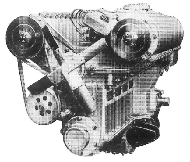
Although the engine’s size was not stated, a Michel engine was extensively run in a truck testbed and reportedly gave good results. However, the engine never entered production. The Michel line of engines was supposed to be made under license in the United Kingdom by Tekon Development Ltd and called the Stellar. However, it does not appear that any engines were made.

*Please note, the Hermann Michel discussed in this article is not the Nazi war criminal with the same name.

Michel 12-cylinder opposed piston engine

A Michel engine with four groups of three opposed-piston cylinders. This engine had a total of 12 cylinders. Note the four square exhaust ports on the lower cylinder bank.

Sources:
– “Two-Stroke-Cycle Internal-Combustion Engine” US patent 1,603,969 by Hermann Michel (granted 19 October 1926)
– “Engine, and Particularly Internal Combustion Engine” US patent 1,568,684 by Hermann Michel (granted 5 January 1926)
– “Comments on Crankless Engine Types” NACA Technical Memorandum No. 462, May 1928 (Translated from “Motorwagen” 20 November 1927) 12.8 MB
High Speed Diesel Engines by Arthur W. Judge (1941)
The Modern Diesel fourth edition no date Illiffe & Sons Ltd
New Motoring Encyclopedia (complete work 1937)
Ungewöhnliche Motoren by Stefan Zima and Reinhold Ficht (2010)

Miller 1113 V-16 Wood Miss America VIII

Miller 1,113 cu in V-16 Marine Engine

By William Pearce

Since 1920, Garfield “Gar” Wood had held the Harmsworth Trophy. Conceived of by British newspaper magnate Alfred Harmsworth, the Trophy was awarded to the winner of an international motorboat race. Wood had won the race each of the six times it was held from 1920 to 1930. But for the 1931 race, held on the Detroit River in Michigan, he was not certain about his chances.

Miller 1113 V-16 Wood Miss America VIII

The 1,113 cu in (18.25 L) Miller V-16 engine complete with Schwitzer-Cummins Roots-type superchargers and Miller carburetors. Note the large, single exhaust manifold.

The twin Rolls-Royce R-powered Miss England II would be representing Britain in the race. The Rolls-Royce R engine was developed for the Schneider Trophy seaplane race and brought the British victory in the 1929 race (and later the 1931 race). In 1930, two 1,800 hp (1,342 kW) Rolls-Royce R engines were installed in a new boat, the Miss England II, for an attempt on the world water speed record. On 13 June 1930, Henry Segrave drove Miss England II to a new speed record of 98.76 mph (158.94 km/h) on Lake Windermere, beating the record set by Wood. Tragically, the boat capsized on a third run, and Segrave died from his injuries shortly after.

On 20 March 1931, Wood regained the speed record by being the first to break the 100 mph (160 km/h) mark. He ran 102.256 mph (164.565 km/h) in his twin Packard V-12-powereded Miss America IX speedboat. But Miss England II had been recovered and repaired. On 2 April 1931, Kaye Don (Kaye Donsky) drove Miss England II to a new record at 103.49 mph (166.55 km/h). Don, possessing what was officially the world’s fastest boat, issued a challenge to Wood for the Harmsworth Trophy.

Miller V-16s in Wood Miss America VIII Oct 1931

An image from October 1931 showing the Packard-powered Miss America IX on the left and the Miller-powered Miss America VIII on the right, both being prepared to launch on the Harlem River. Note that the right bank of the Miller engine is staggered behind the left bank, a necessity of the side-by-side connecting rod arrangement. Also note the mirrored supercharger/induction installation. Individual exhaust stacks were installed on the engines but are obscured by covers in the image.

While at the Indianapolis 500 auto race in May 1931, Wood had a conversation with legendary engine builder Harry A. Miller. They discussed what was needed to defeat Miss England II. They decided that Wood needed more engine power to literally propel him to victory. Miller believed he had an engine design that was up to the challenge. Convinced of their potential, Wood ordered two of these engines for installation in his Miss America VIII boat that currently had twin Packard 1M-2500 engines of around 1,000 hp (746 km/h).

Miller and his incredible draftsman Leo Goossen went to work designing the new engine. In the meantime, Don and Miss England II raised their own record to 110.223 mph (177.387 km/h) on 9 July 1931. This necessitated the Miller engines to be further refined to produce even more power. The Harmsworth Trophy would be held in early September, so there was not much time to design, build, test, and install the engines.

Miller V-16 Wood Miss America VIII at speed

The Miller V-16-powerd Miss America VIII at speed on the Harlem River with Gar Wood as the driver on 25 October 1931. The boat would reach 104 mph (167 km/h).

The engine Miller designed for Wood was a V-16 with 54 degrees between the two banks of eight cylinders. Two cast iron blocks of four cylinders made up each bank. The bore was 4.4375 in (112.7 mm); the stroke was 4.5 in (114.3 mm), and total displacement was 1,113.5 cu in (18.25 L). Each cylinder had two intake and two exhaust valves that were 1.6875 in (42.86 mm) in diameter. The valves were actuated by dual overhead camshafts that were geared to the crankshaft at the front of the engine.

The crankcase was aluminum and supported the crankshaft through five main bearings. The one-piece crankshaft was made from a steel billet. The forged, tubular, steel connecting rods were of a side-by-side arrangement and shared a 3 in (76.2 mm) diameter crankpin. Ignition was provided by two 8-cylinder Bosch magnetos firing one spark plug per cylinder. Induction for each bank was provided by a 3 in (76.2 mm) Miller carburetor attached to a Schwitzer-Cummins Roots-type supercharger driven at .667 crankshaft speed at the rear of the engine. The superchargers provided 10 psi (.69 bar) boost that allowed the engine to produce 1,325 hp (988 kW) at 4,000 rpm and 1,800 hp (1,342 kW) at 6,000 rpm. The V-16 was 90 in (2.29 m) long, which included 18.5 in (.47 m) for the superchargers. The engine was 28 in (.71 m) wide, or 35 in (.89 m) including the superchargers and their carburetors. Its height was 24.25 in (.62 m), and the engine weighed only 1,625 lb (737 kg).

Miller V-16 Wood Miss America VIII

A work of art—one of the restored Miller V-16 engines before installation in Miss America VIII. Note the Bosch magnetos. (Sunnyland ACBS image)

On 25 August, the first engine ran for the first time, just 10 days before the scheduled race. Everything went well, but there certainly was not much time to get the engines ready and installed by the first heat race scheduled for 5 September. Reportedly, on further running, the engines had trouble reaching 6,000 rpm and would not run at more than 4,200 rpm. However, one engine was damaged during a test run, resulting in them not being ready for the Harmsworth Race. Some sources say the damage occurred after the engines were installed in Miss America VIII.

Miller V-16s in Wood Miss America VIII

The functioning but unsupercharged Miller V-16s engines in Miss America VIII under restoration. (Mecum Auctions image)

The Harmsworth Race was postponed two days due to weather, and the Packard engines were reinstalled in Miss American VIII. The event turned out to be quite strange. Wood, in Miss America IX, and Don, in Miss England II, both jumped the start of the second heat by more than five seconds and were disqualified. Both racers pressed on unaware of the disqualification. On the second turn, Miss England II capsized in the wake of Miss America IX. Wood’s brother, George Wood, went on to win the trophy at 85.86 mph (138.78 km/h) in the Packard-powered Miss America VIII.

The issues with the 16-cylinder Millers were worked out, and they were reinstalled in Miss America VIII. On 25 October 1931, Gar and George Wood made a speed record attempt on the Harlem River in New York but only recorded a speed of 104 mph (167 km/h).

Miller V-16 Wood Miss America VIII complete

A fairly recent image of the Miller V-16 engines installed in Wood’s Miss America VIII. (Mecum Auctions image)

Minus the superchargers, the 1,113 cu in (18.24 L) Miller V-16s were sold to Howard “Whitey” Hughes. The now normally aspirated V-16 engines had four carburetors and produced around 930 hp (694 kW) at 4,500 rpm. Hughes used one engine in his race boat Dukie. Eventually, the engines were sold again and passed through a few different owners. Recently, the Miller engines were reunited with the Miss America VIII hull under restoration. In January 2012, the partially restored Miss America VIII and the Miller V-16 engines, including the original superchargers, were offered at auction in Florida. Although the bidding got to $700,000, it did not meet the reserve price. One can only hope that this engine and boat combination will be finished and roar to life once again.

Below is a video from Mecum Auctions giving some history about the Miss America VIII boat and its Miller engines.

Sources:
The Miller Dynasty by Mark L. Dees (1981/1994)
The Marvelous Mechanical Designs of Harry A. Miller by Gordon Eliot White (2004)
The Harmsworth Trophy by Donald W. Paterson (2003)
http://www.mecum.com/auctions/lot_detail.cfm?LOT_ID=FL0112-121272
http://www.vintagehydroplanes.com/boats/miss_america_8/miss_america_8.html
http://www.lesliefield.com/other_history/speedboat_kings_13_kaye_don.htm
http://www.lesliefield.com/other_history/speedboat_kings_14_sinking_of_miss_england_ii.htm

Duesenberg 12-Cylinder Marine Engine and the Disturber IV

By William Pearce

In 1910, the relatively unknown Fred and Augie Duesenberg began designing what would become their walking beam engine. This style of engine had a unique valve arrangement in which horizontal valves, perpendicular to the cylinder axis, opened into a small space above the cylinders. The valves were actuated by very long and large rocker arms, referred to as “walking beams.” By 1913, Duesenberg engines had attracted some attention and were noticed by Commodore James A. Pugh.

Duesenberg Inline-12 Marine engine

The Duesenberg straight-12 marine engine of over 750 hp. Large aluminum covers protected the walking beam rockers of each cylinder pair.

Pugh was interested in building a boat to win the Harmsworth Trophy (British International Trophy for Motorboats) in 1914 and bring the trophy back to the United States. The Harmsworth Trophy was held each year by the country that won it the previous year. The British had won the trophy in 1913 (and 1912), and the 1914 race was to be held on Osborne Bay, England. Pugh was building a 40-foot (12.2 m) hydroplane named Disturber IV and needed powerful engines to ensure victory. Pugh brought the Duesenbergs into the project, and the Duesenbergs began designing a truly unique engine to power Pugh’s new boat.

Duesenberg Straight-12 aluminum crankcase

The one-piece aluminum crankcase for the Duesenberg straight-12 engine.

The Disturber IV was to be powered by two separate straight 12-cylinder engines. Each engine was over 10-feet (3 m) long and was comprised of six two-cylinder blocks mounted on a one-piece crankcase. Each two-cylinder block was water-cooled with the intake valves in the middle of the block and the exhaust vales on the outside. The intake and exhaust valves were operated by long walking beam rockers. A single updraft carburetor provided the fuel/air mixture to a split manifold that fed four cylinders. Each cylinder had two spark plugs. Lubrication was provided by a pressurized oil system, a now-universal concept that was just being introduced at the time. The single-piece crankshaft was supported by seven main bearings.

The use of aluminum was rare for the time, yet the Duesenbergs used it extensively in the engine’s design. The crankcase was one of the largest aluminum forgings made at the time and weighed 365 lb (166 kg) before the final machine work. Magnalite aluminum pistons were used, and the walking beam rocker arm covers were aluminum.

The inline 12-cylinder engine had a bore of 6.75 in (171 mm) and a stroke of 7.5 in (191 mm). Total displacement was 3,221 cu in (52.8 L). The engine developed 750 hp (559 kW) at 1,500 rpm and 800 hp (597 kW) at 1,600 rpm. While it is possible that more power could have been obtained at a higher rpm, the often quoted 900 hp (671 kW) seems a little optimistic. The engine weighed 2,700 lb (1,225 kg). With both engines installed in Disturber IV and running at full speed, total fuel burn was reported at 132 gallons (500 L) per hour.

These mighty 12-cylinder engines were built at the Duesenberg Motor Company factory in St. Paul, Minnesota. The engines were finished and installed in Disturber IV in mid-1914. The installation of the engines was mirrored so that the intake of the left engine was on the left side and the intake of the right engine was on the right side. This effectively allowed the engines to run in opposite directions. Thus, each engine’s single propeller rotated in opposite directions. The propellers were 24 in (610 mm) in diameter with a 40 in (1 m) pitch. Through a step-up gearbox with a ratio of 1.25 to 1, each propeller turned at 2,000 rpm while the engine speed was 1,600 rpm.

The Disturber IV being launched on he Chicago River 2 July 1914. (Image DN-0063061, Chicago Daily News negatives collection, Chicago History Museum)

The Disturber IV being launched on the Chicago River on 2 July 1914. (Image DN-0063061, Chicago Daily News negatives collection, Chicago History Museum)

On 2 July 1914, the Disturber IV was officially launched on the Chicago River. It underwent trials for a short time, achieving speeds in excess of 50 mph (80 km/h), before it was shipped to New York on 12 July 1914. In New York, it was loaded on the S.S Minnetonka and shipped to Cowes, England for the Harmsworth Trophy race to be held on 15-18 August 1914. Augie Duesenberg accompanied the boat to ensure the engines would be trouble free. While the Disturber IV was in transit, Archduke Franz Ferdinand of Austria was assassinated, World War I began, and the Harmsworth Trophy was cancelled. The Disturber IV arrived in England only to be immediately shipped back to the United States without ever touching the water.

It had been a rushed pace from the inception of the 12-cylinder engines to the voyage back to the United States. Now with spare time on his hands, Augie began to think of ways to improve the 12-cylinder engines. After arriving back in the United States, the engines were shipped back to the Duesenberg factory in St. Paul where they were disassembled and modified. The exact extent of the modifications are not known, but it was during this rebuild that the large, water-jacketed exhaust manifold was replaced by individual, vertical exhaust stacks.

Disturber IV July 1914

Disturber IV in July 1914 with the large, water-jacketed exhaust manifold atop each engine and leading out the boat’s stern.

By October 1914, the 12-cylinder engines were back in Disturber IV, and the boat was turned loose on Lake Michigan. Pugh, accompanied by mechanics Charles Swanson and Henry Suttkas, won a special race off the coast of Chicago, Illinois on 20 October 1914. Two 14.83 mi (23.87 km) laps were run for a total distance of 29.66 mi (47.74 km). Disturber IV completed the first lap at a record speed of 56.6 mph (91.1 km/h). The second lap was completed at 47.0 mph (75.6 km/h), and the boat averaged 51.4 mph (82.7 km/h) over the total course. Disturber IV finished 17 minutes ahead of the second place boat.

Disturber IV Duesenberg

By October 1914, the Duesenberg engines in the Disturber IV had been modified with individual exhaust stacks. The pipes leading overboard were the cooling water outlet for each cylinder pair. Note the intake manifolds on the right engine.

In 1915, the American Speed Boat Championship was held over three days in early September on Lake Michigan. Each day a two lap race was made over a 15.25 mi (24.54 km) course for a total distance of 30.5 mi (49.09 km). The winner of the first day’s race would receive the Wrigley Trophy. During the first race, Disturber IV was in the lead after completing the first lap at 55.4 mph (89.2 km/h). The second lap was completed at 44.7 mph (71.9 km/h), and the boat averaged 49.5 mph (79.7 km/h) over the entire distance. Disturber IV won the Wrigley Trophy—and finished nearly 10 minutes ahead of the second place boat, Miss Detroit. During the second day’s race, Disturber IV turned the first lap at 55.3 mph (89.0 km/h) and the second at 55.2 mph (88.8 km/h), averaging 55.2 mph (88.8 km/h) over the 30.5 mi (49.09 km/h) total distance. Disturber IV was undefeated the third day and won the American Speed Boat National Championship.

A few days later on 12 September 1915, with the Duesenberg engines running at a smooth 1,600 rpm, Pugh and the Disturber IV became the first to break the mile-a-minute mark on water. Pugh made six timed speed runs on Lake Michigan near Chicago. His fastest run was 61.2 mph (98.5 km/h), but is often reported as 62 mph (99.8 km/h), and another run was at 60.4 mph (97.2 km/h). Disturber IV’s six run average was at 59.2 mph (95.3 km/h).

Disturber IV 1915 Race

Disturber IV in the 1915 American Speed Boat Championship on Lake Michigan. In the background are Peter Pan and Miss Detroit.

Late in 1915, Pugh put Disturber IV in storage and stated he would not race again until the next international meet. Pugh had built the Disturber IV solely to win the Harmsworth Trophy, and he found dominating other boats on Lake Michigan was not very fulfilling. With World War I raging, all international meets had been cancelled until the end of hostilities. What Pugh did not know was that the war would continue for another three years, and the next Harmsworth Trophy race would not be held until 1920. When peace did return, the world was a different place. The war had advanced engine technology, and the powerful Disturber IV was no longer on the cutting edge. The ultimate fate of the Disturber IV and its straight-12 Duesenberg engines is not known.

Disturber IV’s Duesenberg engines attracted so much interest that the Loew-Victor Company retained Fred Duesenberg as a designer. Fred went on to design six- and eight-cylinder engines based on the 12-cylinder engine’s design. In early 1917, Duesenberg Motor Company and the Loew-Victor Engine Company combined to form the Duesenberg Motors Corporation. Although it was not a direct path to the Duesenberg automobile, the engines for the Disturber IV helped open the door to the Duesenberg’s future endeavors.

Sources:
– “Walking Beam on Water” by Joseph Freeman, Automobile Quarterly, Vol. 30, No. 4 (1992)
– “A Large Aluminum Crank Case,” The Foundry, July 1914
– “Disturber Makes Record at Chicago” Power Boating, December 1914
– “Early Days of Aluminum Pistons” by Joseph Leopold, The Automobile, 7 October 1915
– “Chicago Races,” The Rudder, October 1915
– “Disturber IV Sets Mile-a-Minute Mark” by Jack Proctor, Sporting Life, 25 September 1915
Duesenberg Aircraft Engines: A Technical Description by William Pearce (2012)

Duesenberg W-24 Marine Engine

By William Pearce

Although his father was a co-founder of the Dodge Brothers Company, progenitor to today’s Dodge automobile company, Horace Elgin Dodge Jr. did not follow his father into the automobile business. But like his father, he was very interested in watercraft. In 1923, after his father had passed, he founded Dodge Boat Works in Detroit, Michigan. This venture was backed by a $2 million investment from his mother, Anna Thompson Dodge.

Side view of the J. Paul Miller-developed Duesenberg W-24 engine.

Side view of the J. Paul Miller-developed Duesenberg W-24 engine.

Dodge was very involved in boat racing, and he wanted to create a boat that would be unbeatable. In 1925, Dodge approached Duesenberg Brothers Racing to build an engine to propel him to victory in the Gold Cup race. An agreement was made, and a contact was signed on 27 January 1926—$32,500 for the construction of two complete engines with enough spare parts to build a third. The first engine was to be delivered on 15 June 1926, with the second following on 6 July 1926. Although Fred Duesenberg was involved with the engine project, it was most likely Augie Duesenberg who did the majority of the work.

The contracted engine was essentially three straight-eight engines on a common aluminum crankcase, creating a W-24. Why a “W” engine configuration was chosen is not known, but it does provide for a powerful engine in a fairly compact space. At this same time in history, the Napier Lion W-12 engine was powering record-setting air, land, and marine speed machines, and it is easy to see how the Lion could have served as inspiration.

Front view of the Duesenberg W-24 under construction.

View of the Duesenberg W-24 under construction.

The engine’s bore was 2.875 in (73 mm) and stroke was 4.0 in (102 mm), giving a total displacement of 623 cu in (10.2 L). The two side banks were angled 60 degrees from the center vertical bank. Each of the W-24’s engine banks was made up of two four-cylinder blocks with integral heads. The first four-cylinder blocks were supposedly made of cast iron, but later cylinder blocks were cast aluminum with steel cylinder liners. The engine’s single crankshaft was supported by five main bearings. The connecting rods were of the tubular type, with the master rod in the center bank and an articulated rod for each outer bank.

Four valves per cylinder operated in a pentroof combustion chamber. All together, the engine’s 96 valves took about a week of labor to adjust. The valves were actuated in each engine bank by dual overhead camshafts that extended the length of the engine. The camshafts were geared to the crankshaft via idler gears. Each block of four cylinders had five exhaust ports. The three middle exhaust ports each shared two exhaust valves. Exhaust from each bank was collect in a single water jacketed manifold. One spark plug was installed in each cylinder and fired by a camshaft-driven Delco distributor mounted at the rear of each cylinder bank.

The complex gear-drive arrangement for the camshafts at the rear of the 24-cylinder Duesenberg.

The complex gear-drive arrangement for the camshafts at the rear of the 24-cylinder Duesenberg. The pinion on the crankshaft had 17 teeth, the intermediate gears had 74 teeth, and the camshaft gears had 34 teeth. The center intermediate gear engaged an idler gear that had 45 teeth. The gearing drove the camshafts at half engine speed.

Initially, one updraft carburetor fed air to each of the six four-cylinder blocks. Poor fuel distribution resulted, and the engine never ran well. The updraft carburetors were replaced with downdraft carburetors, and the W-24’s running improved, but it was still not perfect. The six downdraft carburetors were replaced by 12 Zenith downdraft carburetors, improving performance yet again. Finally, 12 Holley downdraft carburetors replaced the Zeniths, and the engine began to run smoothly. Although running better than ever, the W-24 only produced a disappointing 475 hp (354 kW).

The first engine was delivered to Dodge in 1927. Earlier that year, J. Paul Miller began working at the Duesenberg factory and was involved with W-24 engine for many years. Some of Miller’s first changes were installing I-beam connecting rods in place of the tubular ones and replacing the Delco distributors with Bosch magnetos. From 1929 to 1935, Miller worked for Dodge and continued to develop the engine. Unfortunately for Dodge, the 24-cylinder engines brought nothing but frustration. As a result, he never paid Duesenberg the last $2,000 for the engines.

Rear of the 24-cylinder Duesenberg showing two two-barrel carburetors feeding the supercharger. Note the Bosch magnetos mounted driven by the camshafts.

Rear of the 24-cylinder Duesenberg showing two two-barrel carburetors feeding the supercharger. Note the camshaft-driven Bosch magnetos.

The 1931 Gold Cup race was held on Lake Montauk in New York, and the W-24 engine was installed in Dodge’s Miss Syndicate III boat. Miss Syndicate III failed to finish the first heat. In 1932, Miss Syndicate III had been renamed Delphine V. Dodge Sr. had named a yacht after his daughter, and Dodge Jr. continued the “Delphine tradition,” naming numerous boats after his sister. Again, the Gold Cup race was held on Lake Montauk in New York. During the first heat race, the W-24-powered Delphine V dropped out after three laps. Dodge entered five boats for the 1933 Gold Cup race held on the Detroit River. A 24-cylinder Duesenberg was installed in two of the entries: the new Delphine VIII and the new Delphine IX. That year, Delphine VIII failed to start, and Delphine IX did not finish a single heat. In 1934, in disgust, Dodge sold one (but probably both) W-24 engine to Herb Mendelson.

Before the sale, Dodge was inspired by the performance of the supercharged Packard engine in one of this other boats, Delphine IV. Since a rule change allowed superchargers to be used starting in 1935, Dodge had commissioned Miller to design a supercharger for the W-24. This unfinished project was sold to Mendelson, and Miller was retained by Mendelson to continue the work on the engine. It was Miller’s refinements of the supercharged engine that really brought the W-24 to life. The supercharger used an 8 in (203 mm) impeller and spun at 6.5 times crankshaft speed (32,500 rpm at 5,000 rpm engine speed), creating 15 psi (1.03 bar) of boost. Initially, two two-barrel carburetors were used on the supercharged engine, but these were replaced by a single four-barrel Stromberg carburetor. Along with new Miller-designed intake manifolds, the fuel distribution problems were finally solved. The exhaust manifolds were discarded and replaced by 30 vertical exhaust stacks extending into the air. With the changes, the engine weighed 1,400 lb (635 kg) and was referred to as the “Mendelson-Duesenberg W-24.” The engine began to run like a champion and now produced over 850 hp (634 kW) at 5,000 rpm. Reportedly, at full song the engine produced a sound like nothing else on earth.

The W-24 being installed in in the Arena-designed Notre Dame by Gene Arena, Walter Schmid, and Bert MacKenzie.

The W-24 being installed in in the Arena-designed Notre Dame by Gene Arena, Walter Schmid, and Bert MacKenzie.

Mendelson installed the W-24 into his boat, the Clell Perry-designed rear-engined Notre Dame (the first). Its first competition was the 1935 President’s Cup race on the Potomac River. Perry was the driver and won the race. In 1937, Perry was again at the controls when the W-24-powered Notre Dame won the Gold Cup race, held on the Detroit River, averaging 63.68 mph (102.48 km/h) over the 90 mile (145 km) course.

While making a high speed run on the Detroit River in preparation for the 1938 Gold Cup race, Perry was injured when the new Notre Dame (the second) boat went out of control and flipped over. (This accident possibly destroyed one of the W-24 engines.) The new Notre Dame was repaired, and Dan Arena took over the driving duties. He finished second in the President’s Cup race but did not like the boat’s stability. Mendelson asked Arena what he thought was needed to cure the stability issues, and Arena said, “Build another boat.” Mendelson agreed, and Arena designed a new 22 ft (6.7 m) boat, again named Notre Dame (the third), with the W-24 engine placed in front of the driver.

Dan Arena (standing) preparing to run the W-24-powered Notre Dame with his brother Gene as the riding mechanic, as Bert MacKenzie makes final preparations.

Dan Arena (standing) preparing to run the W-24-powered Notre Dame with his brother Gene as the riding mechanic, as Bert MacKenzie makes final preparations.

After a bit of a rough start, Arena won the 1939 and 1940 President’s Cup races in the new Notre Dame. In 1940 on the Detroit River, the W-24 powered the Notre Dame to a new class speed record of 100.987 mph (162.523 km/h). The boat was placed in storage during World War II but was taken out in 1947 and won the Silver Cup race on the Detroit River and finished second in the President’s Cup race. By this time, competitors were installing WWII surplus Allison engines in their boats, and the Duesenberg W-24 could no longer compete. The engine was removed and placed in storage.

At least one Duesenberg W-24 engine survives along with many spare parts. As of 2013, the engine is owned by Gerard Raney and has been rebuilt for installation in a Notre Dame (the third) replica that is under construction. In the mid-1990s, Miller and Arena were both involved in the project, which is based out of the San Francisco Bay Area. Undoubtedly, the engine and boat combination will be quite a sight when the project is finished.

Duesenberg W-24 1996 copy

The surviving Duesenberg W-24 engine owned by Gerard Raney as seen in 1996. Note that each cylinder bank is made up of two four-cylinder blocks; the gap between the blocks is visible on the bank nearest the camera. The camshaft housings extend the length of the engine. (Pat O’Connor image)

Sources:
– “The Duesenberg W-24” by Dean Batchelor, Road & Track, August 1992
– “That Kid From Oakland” by Frank Gudaitis, Nautical Quarterly, No. 40, Winter 1987
– “They Always Called Him Augie” by George Moore, Automobile Quarterly, Vol. 30, No. 4 (1992)
The Classic Twin-Cam Engine by Griffith Borgeson (1979/2002)
Classic American Runabouts: Wood Boats, 1915-1965 by Ballantyne and Duncan (2005)
http://www.vintagehydroplanes.com/apba_history/notebook/1996_08.html
The Dan Arena Story by Fred Farley – ABRA Unlimited Historian
The Notre Dame Story by Fred Farley – ABRA Unlimited Historian
1933 – The Year of the Dodge Navy by Fred Farley – ABRA Unlimited Historian
http://www.findagrave.com/cgi-bin/fg.cgi?page=sh&GRid=14820517