Monthly Archives: September 2016

savoia-marchetti-s65-calshot

Savoia-Marchetti S.65 Schneider Racer

By William Pearce

After the Italian team was defeated on its home turf at Venice, Italy in the 1927 Schneider Trophy Race, the Italian Ministero dell’Aeronautica (Air Ministry) sought to ensure victory for the 1929 race. The Ministero dell’Aeronautica instituted programs to enhance aircraft, engines, and pilot training leading up to the 1929 Schneider race. Early in 1929, the Ministero dell’Aeronautica requested racing aircraft designs from major manufacturers and encouraged unorthodox configurations.

savoia-mrachetti-s65-orig-config

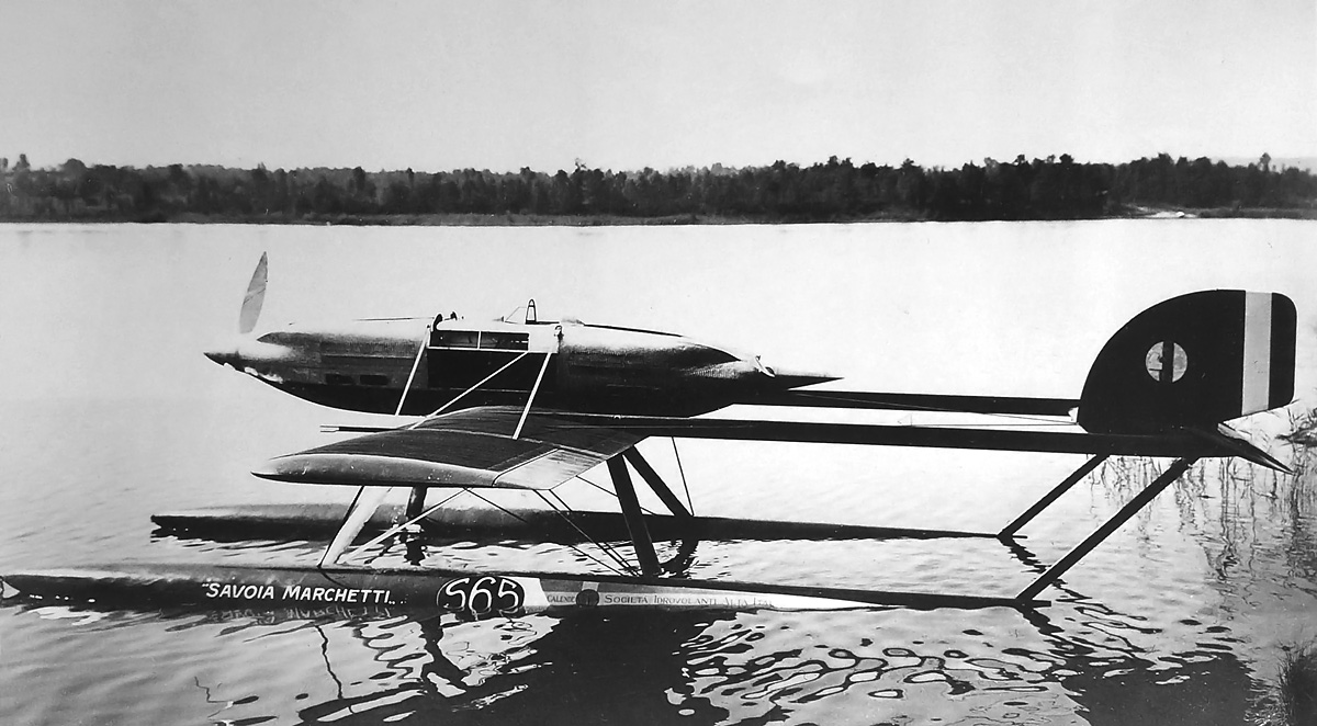
The Savoia-Marchetti S.65 in its original configuration. Note the single strut extending from each float to the tail, the short tail and rudder, and the short windscreen.

Alessandro Marchetti was the chief designer for Savoia-Marchetti and was preoccupied with the design of the long-range S.64 aircraft. Originally, he did not submit a Schneider racer design, but the Ministero dell’Aeronautica encouraged him to reconsider. Soon after, Marchetti submitted the rather unorthodox S.65 design. On 24 March 1928, the Ministero dell’Aeronautica ordered two S.65 aircraft and allocated them the serial numbers MM 101 and MM 102.

The Savoia-Marchetti S.65 was a low-wing, tandem-engine, twin-boom monoplane that utilized two long, narrow floats. The aircraft was designed to incorporate the largest amount of power in the smallest package. The S.65’s tension rod and wire-braced wings were made of wood and almost completely covered with copper surface radiators. The floats were made of wood (some say aluminum), had a relatively flat bottom, and housed the S.65’s fuel tanks. The floats were around 28 ft 8 in (8.75 m) long and were mounted on struts. Originally, one strut extended from the rear of each float to the tail, but a second strut was later added.

savoia-marchetti-s65-2nd-config

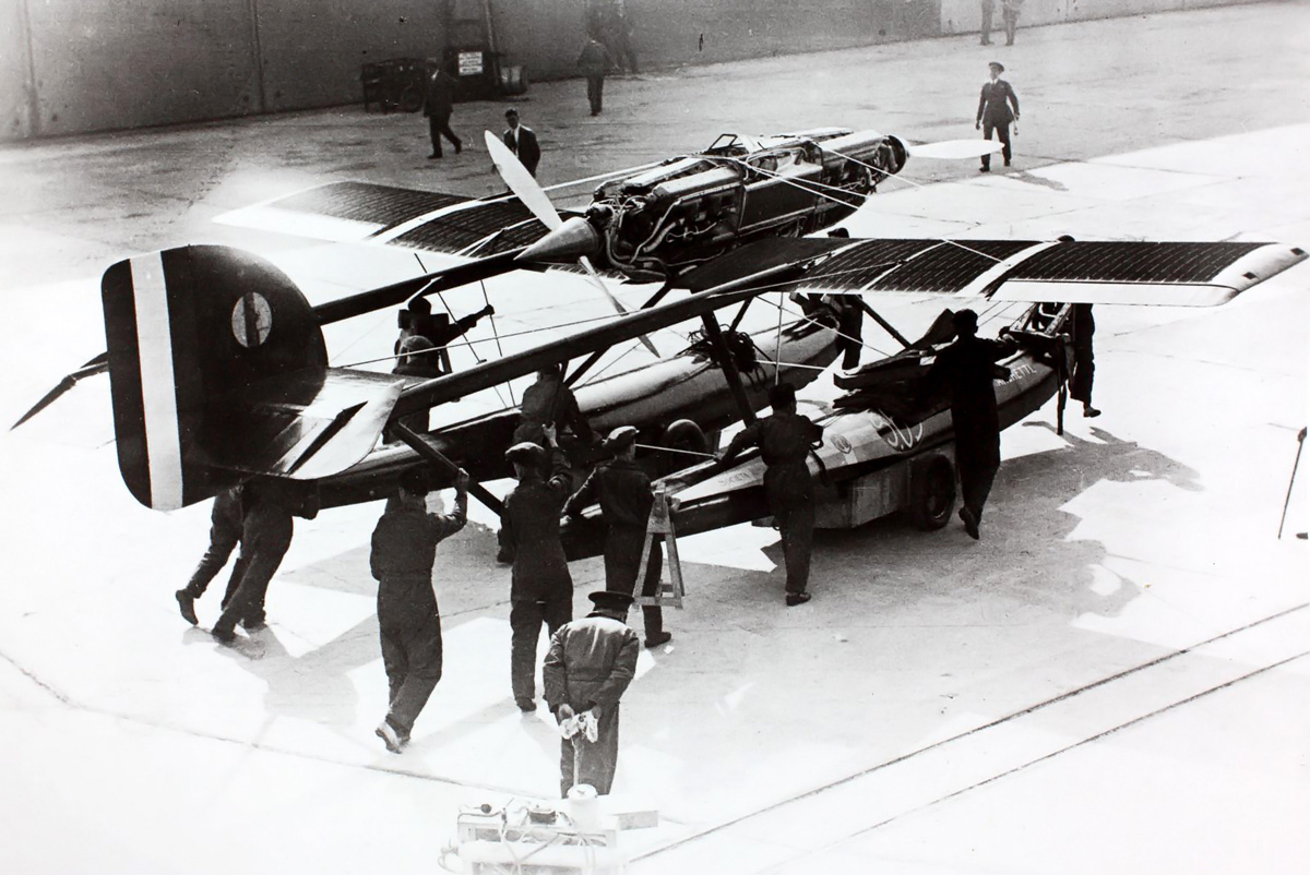
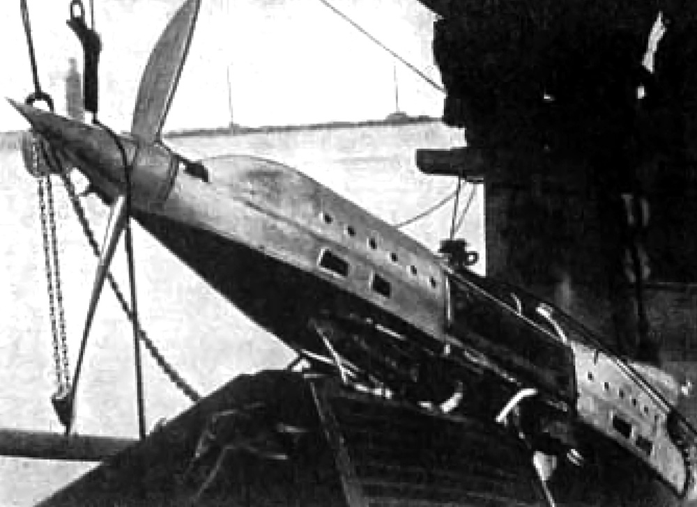
The S.65 has been modified with an additional strut extending from each float to the tail. The tail and rudder have also been extended below the horizontal stabilizer. Note that the windscreen has not changed, that the rudder has a rather square lower trailing edge, and that there are no handholds in the wingtips.

A narrow boom extended behind each wing to support the tail. The boom was hollow and had flight cables running through its interior. Sources disagree on whether the booms were made of metal or wood. The horizontal stabilizer was mounted between the ends of the booms. The vertical stabilizer was positioned in the center of the horizontal stabilizer. Originally, the rudder and tail extended only above the horizontal stabilizer, and the rudder was notched to clear the elevator. Later, the tail and rudder were enlarged and extended below the horizontal stabilizer, and the elevator was notched to clear the rudder. The tail and all control surfaces were made of wood and were fabric-covered.

Attached to the wing was a small fuselage nacelle that housed two Isotta Fraschini Asso 1-500 engines. The engines were mounted in a push-pull configuration with one engine in front of the cockpit and the other behind. The nacelle was made of a tubular steel frame and covered with aluminum panels. Oil coolers were mounted on both sides of the cockpit between the engines. Two windows to improve the pilot’s lateral visibility were positioned above each oil cooler. Just behind the front engine was a windscreen for the cockpit. Initially, a short windscreen was installed, but this was later replaced by a longer, more streamlined unit. The fuselage nacelle was around 18 ft (5.48 m) long, including the propeller spinners.

isotta-fraschini-1-500-s65-engine

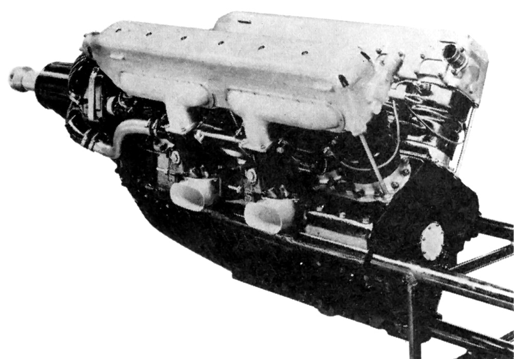
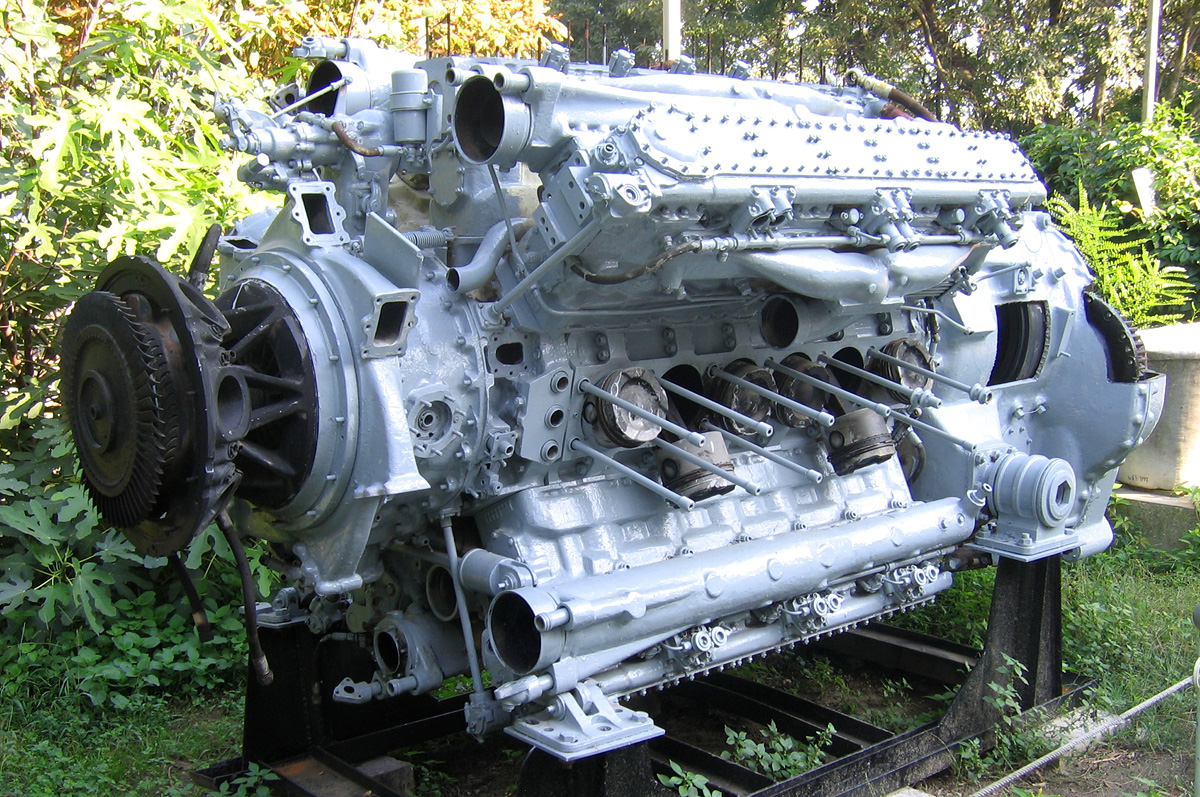
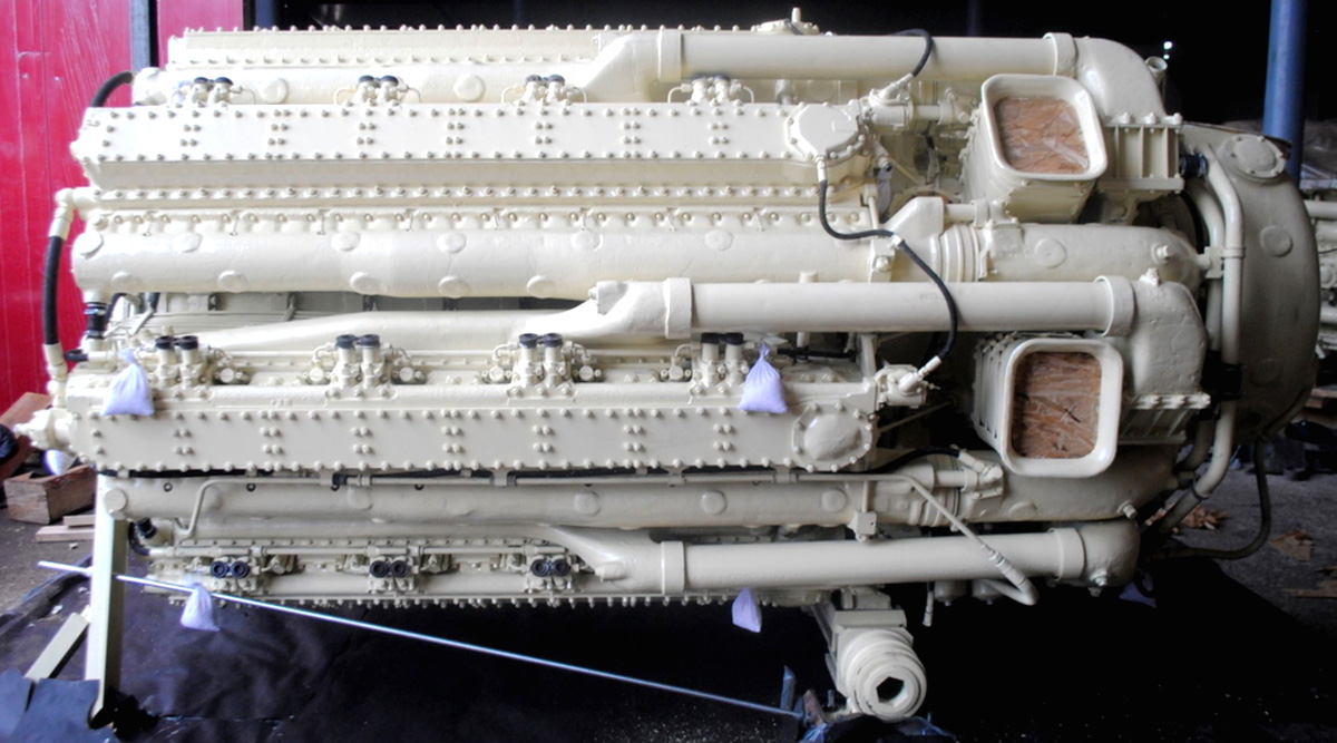
The 1,050 hp (783 kW) Isotta Fraschini Asso 1-500 engine. It is unclear how much this engine differed internally from a standard Asso 500 engine. The three cantilever mounts and the nearly-flush rear of the engine can clearly be seen. The exhaust ports have been relocated from the outer side of the cylinder head to the Vee side. A water pump and magneto are just visible on the extended gear reduction case. The vertical ribbing on the lower crankcase served to increase its strength.

The S.65’s Asso 1-500 V-12 engines were based on the Asso 500 Ri engine and were heavily modified by Giustino Cattaneo, head engineer at Isotta Fraschini. The engine’s crankcase was ribbed and strengthened to become a structural member of the S.65’s fuselage nacelle. Each engine mounted directly to a steel bulkhead on the end of the cockpit via three cantilever supports. The rear of the engine sat flush with the bulkhead. At the front of the engine was an extended gear reduction case which allowed for a streamlined cowling. Engine accessories, such as the two water pumps and two magnetos, were mounted to the gear case. Each Asso 1-500 engine produced 1,050 hp (783 kW) at 3,000 rpm.

At the bottom of each side of the cowling were two inlets. Air flowed from each inlet into a carburetor and then into three cylinders of the engine. Exhaust ports were located on the Vee side of the engine, and the exhaust gases were expelled up though the top of the cowling. Both engines turned counter-clockwise. Since the rear engine was installed backward, the propellers of each engine turned in opposite directions relative to one another. This installation effectively cancelled out the propeller torque that had been an issue for a number of Schneider racers. The metal, two-blade, fixed pitch propellers had a diameter of approximately 7 ft 5 in (2.26 m). The rear propeller’s spinner was about one-third longer than the front spinner.

savoia-marchetti-s65-calshot

The S.65 as seen at Calshot, England. The long windscreen has now been installed. The lower trailing edge of the rudder is now rounded, and the wingtips now have handholds. This image gives a good view of the surface radiators that cover nearly all of the wings. Also visible is the rectangular cover of the exhaust ports between the cylinder banks.

Italian sources and drawings from Savoia-Marchetti list the S.65 as having a wingspan of 31 ft 2 in (9.5 m) and a length of 35 ft 1 in (10.7 m). However, other sources often cite a wingspan of 33 ft (10.05 m) and a length of 29 ft (8.83 m). It is not entirely clear which figures are correct. The weight of the aircraft was approximately 5,071 lb (2,300 kg) empty and 6,173 lb (2,800 kg) loaded. The top speed of the S.65 was estimated between 375 and 400 mph (600 and 645 km/h).

In mid-1929, Alessandro Passaleva, one of Savoia-Marchetti’s pilots, tested the first S.65 (MM 101) on Lake Maggiore, near the company’s factory in Sesto Calende, Italy. Although the aircraft was not flown, Passaleva recommended a number of changes to stiffen and improve the S.65’s tail. The second S.65 (MM 102) was modified with the additional tail brace and extended rudder and tail. It is doubtful that MM 101 was ever flown or that MM 102 was flown on Lake Maggiore. MM 102 was delivered to the Reparto Alta Velocità (High Speed Unit) at Desenzano on Lake Garda in July 1929.

Initial flight tests of the S.65 were conducted by Tommaso Dal Molin and began in late July 1929. This is most likely the first time an S.65 was flown. Dal Molin was an experienced pilot and also small enough to fit inside the S.65’s very cramped cockpit. Some accounts state that Dal Molin did not bother with a parachute because the cockpit was so small, and the rear propeller made bailing out nearly impossible. A number of issues were encountered with the aircraft’s engines and cooling system. In addition, exhaust fumes constantly entered the cockpit.

savoia-marchetti-s65-calshot-runup

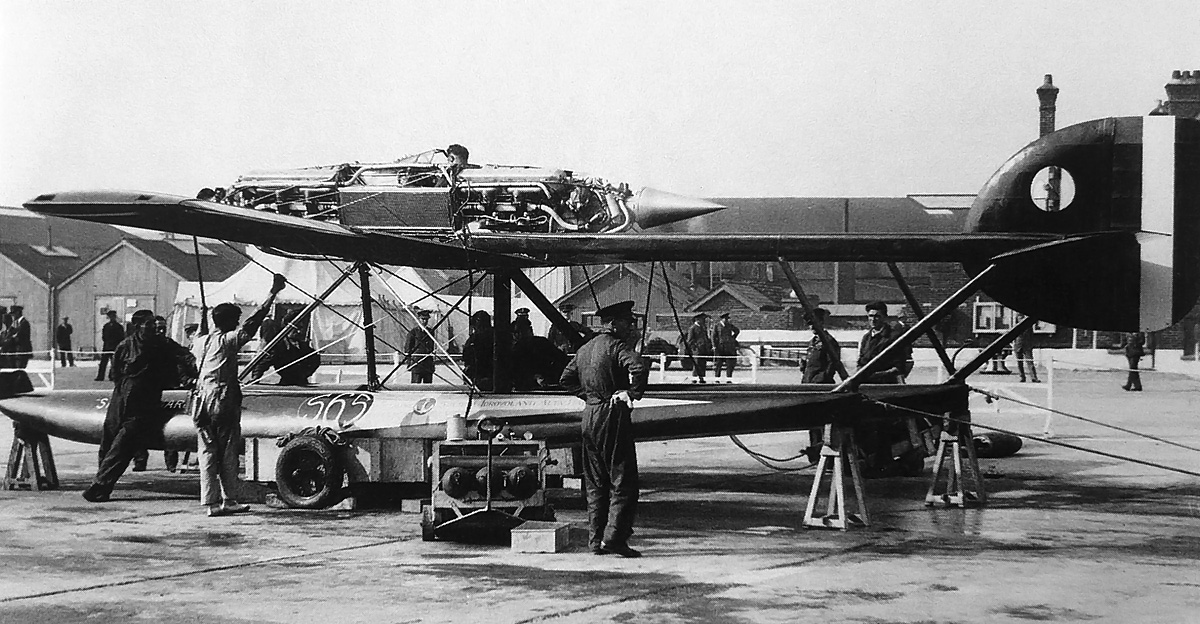
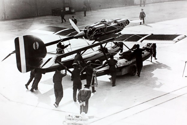
This image shows the S.65’s rear engine being run-up at Calshot. The oil radiator is clearly seen between the two engines, and it gives some perspective as to the small size of the cockpit. Note the various engine accessories mounted to the extended gear reduction case.

It was soon obvious that the S.65 would not be ready in time for the Schneider Trophy Race held on 6–7 September 1929 in Calshot, England. However, the Italians decided to send the aircraft anyway, to give the British team something to consider. Before the S.65 arrived at Calshot, the lower rudder extension was rounded; the longer windscreen was installed, and handholds were added to the wingtips. During the races, the S.65 MM 102 was displayed, and its rear engine was run-up on at least one occasion. Some saw the S.65 as a sign of future high-speed aircraft to come.

Italy had developed four new aircraft for the 1929 Schneider Trophy Race: Macchi M.67, FIAT C.29, Savoia-Marchetti S.65, and Piaggio P.7. The end result was that Italian resources were spread too thin, and none of their aircraft were developed to the point of offering serious competition to the British effort, which was victorious. Once back in Italy, the head of the Reparto Alta Velocità, Mario Bernasconi, decided to recover some pride by making an attempt on the world speed record. Britain had just set a new record on 12 September 1929 at 357.7 mph (575.7 km/h) in its Schneider race-winning Supermarine S6 (N247) piloted by Augustus Orelbar.

savoia-marchetti-s65-dal-molin-calshot

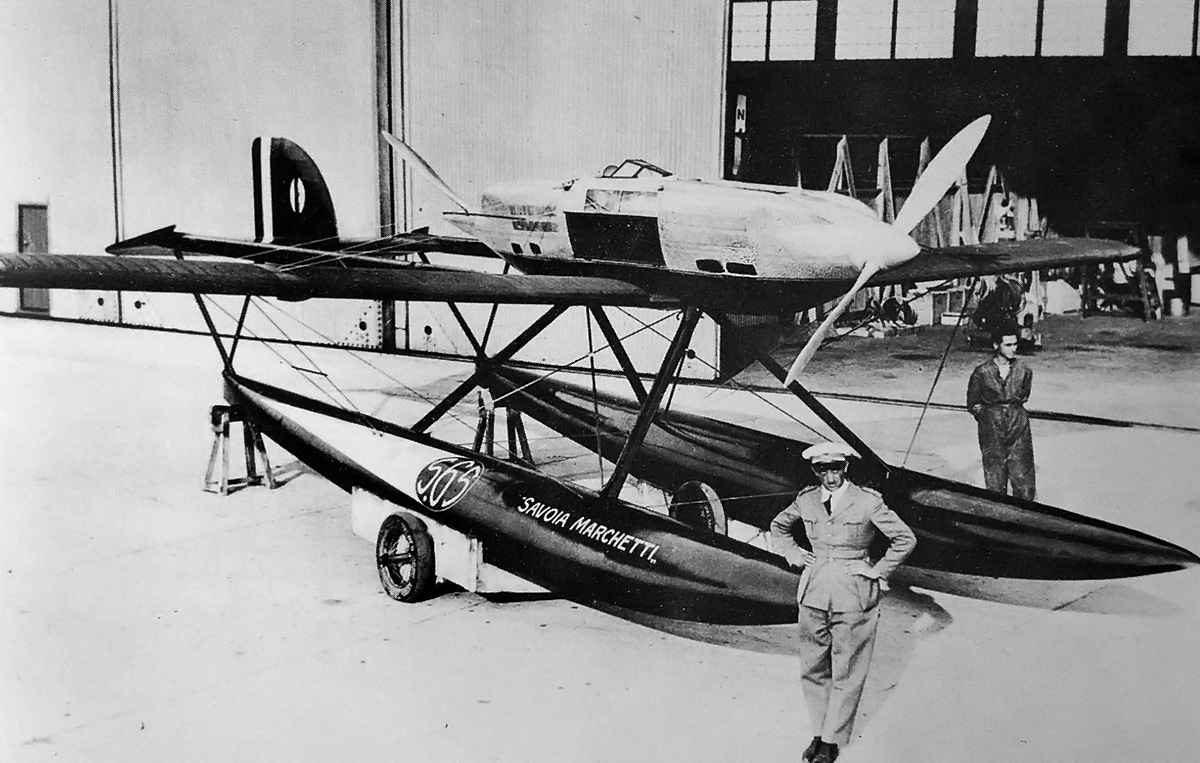
Tommaso Dal Molin poses in front of the S.65. Note the longer windscreen and the side windows just above the oil cooler. Each rectangular port on the cowling leads to a carburetor. Also visible are the louvers that cover the cowling.

The S.65 underwent further refinements in late 1929, and it was believed that the aircraft could exceed the S6’s speed by a reasonable margin. It appears the aircraft was fitted with new aluminum (duralumin), V-bottom floats. In addition, the engine cowling had what appear to be six exhaust ports positioned on each side. Exhaust fumes entering the cockpit was an issue due to the central exhaust location, and relocating the ports to the engine sides (their original location in the Asso 500 engine) would help solve the issue. The carburetor intakes were not changed.

Dal Molin took the S.65 on a test flight from Lake Garda on 17 January 1930 to prepare for his speed record attempt the following day. On 18 January, Dal Molin made three takoff attempts, which were all aborted due to excessive yaw. On the fourth attempt, the S.65 became airborne and then pitched up at an extreme angle. The aircraft stalled some 80 to 165 ft (25 to 50 m) above the water and crashed into the lake. Rescue vessels arrived quickly, but the S.65 with Dal Molin still aboard had quickly sunk 330 ft (100 m) to the bottom of the lake. It was Tommaso Dal Molin’s 28th birthday. A special recovery vessel called the Artigilo retrieved the S.65 on 29 January. Dal Molin’s body was recovered on 30 January. While the exact cause of the crash was never determined, many believe the elevator jammed, resulting in the abrupt pitch up and subsequent stall.

Note: As mentioned above, many sources disagree on various aspects of the S.65. For example, sources (some of which were not used in this article) list the wing spars as being made from four different materials: duralumin, walnut, mahogany, and spruce. While images were closely scrutinized to give an accurate account of the S.65 in this article, only so much can be determined from analyzing a grainy, 85-year-old image. In addition, some sources claim that only one S.65 was built (MM 102). Others say construction of MM 101 was started but never completed, and still others contend that MM 101 was completed and stored at the Reparto Alta Velocità at Lake Garda until 1939.

savoia-mrachetti-s65-recovery

The remains of the S.65 after it was recovered from Lake Garda and placed onboard the Artigilo. The rear engine is in the foreground. Note what appear to be exhaust ports along the sides of the cowling. The aircraft’s fuselage seems to be rather undamaged. Reportedly, the S.65 sank quickly, and some sources claim that Dal Molin could not swim.

Sources:
Schneider Trophy Seaplanes and Flying Boats by Ralph Pegram (2012)
Aeroplani S.I.A.I. 1915–1945 by Giorgio Bignozzi and Roberto Gentilli (1920)
Schneider Trophy Aircraft 1913–1931 by Derek N. James (1981)
MC 72 & Coppa Schneider by Igino Coggi (1984)
L’epopea del reparto alta velocità by Manlio Bendoni (1971)
http://wwwteamgrs-marco.blogspot.com/2015/04/il-recupero-della-salma-del-pilota.html

Zvezda M503 Rear

Yakovlev M-501 and Zvezda M503 and M504 Diesel Engines

By William Pearce

Just after World War II, OKB-500 (Opytno-Konstruktorskoye Byuro-500 or Experimental Design Bureau-500) in Tushino (now part of Moscow), Russia was tasked with building the M-224 engine. The M-224 was the Soviet version of the Junkers Jumo 224 diesel aircraft engine. Many German engineers had been extradited to work on the engine, but the head of OKB-500, Vladimir M. Yakovlev, favored another engine project, designated M-501.

Zvezda M503 front

Front view of a 42-cylinder Zvezda M503 on display at the Technik Museum in Speyer, Germany. Unfortunately, no photos of the Yakovlev M-501 have been found, but the M503 was very similar. Note the large, water-jacketed exhaust manifolds. The intake manifold is visible in the engine Vee closest to the camera. (Stahlkocher image via Wikimedia Commons)

Yakovlev and his team had started the M-501 design in 1946. Yakovlev felt the M-224 took resources away from his engine, and he was able to convince Soviet officials that the M-501 had greater potential. All development on the M-224 was stopped in mid-1948, and the resources were reallocated to the M-501 engine.

The Yakovlev M-501 was a large, water-cooled, diesel, four-stroke, aircraft engine. The 42-cylinder engine was an inline radial configuration consisting of seven cylinder banks positioned around an aluminum crankcase. The crankcase was made up of seven sections bolted together: a front section, five intermediate sections, and a rear accessory section. The crankshaft had six throws and was supported in the crankcase by seven main bearings of the roller type.

Each cylinder bank was made up of six cylinders and was attached to the crankcase by studs. The steel cylinder liners were pressed into the aluminum cylinder block. Each cylinder had two intake and two exhaust valves actuated via roller rockers by a single overhead camshaft. The camshaft for each cylinder bank was driven through bevel gears by a vertical shaft at the rear of the bank. All of the vertical shafts were driven by the crankshaft. The pistons for each row of cylinders were connected to the crankshaft by one master rod and six articulating rods.

Zvezda M503 Rear

Rear view of a M503 on display at Flugausstellung L.+P. Junior in Hermeskeil, Germany. The upper cylinder gives a good view of the exhaust (upper) and intake (lower) manifolds, and the engine’s intake screen can just be seen between the manifolds as they join the compounded turbosupercharger. The exhaust gases exited the top of the turbine housing. (Alf van Beem image via Wikimedia Commons)

Exhaust was taken from the left side of each cylinder bank and fed through a manifold positioned in the upper part of the Vee formed between the cylinder banks. The exhaust flowed through a turbosupercharger positioned at the extreme rear of the engine. Exhaust gases expelled from the turbosupercharger were used to provide 551 lbf (2.45 kN / 250 kg) of jet thrust.

The pressurized intake air from the turbosupercharger was fed into a supercharger positioned between the turbosupercharger and the engine. The single-speed supercharger was geared to the crankshaft via the engine’s accessory section. Air from the supercharger flowed into a separate intake manifold for each cylinder bank. The intake manifold was positioned in the lower part of the Vee, under the exhaust manifold, and connected to the right side of the cylinder bank.

The M-501 had a 6.30 in (160 mm) bore and a 6.69 in (170 mm) stroke. The engine displaced 8,760 cu in (143.6 L) and produced 4,750 hp (3,542 kW) without the turbosupercharger. With the turbosupercharger and the thrust it provided, the engine produced 6,205 hp (4,627 kW). The engine weighed 6,504 lb (2,950 kg) without the turbocharger and 7,496 lb (3,400 kg) with the turbocharger.

Zvezda M503 Bulgaria

This partially disassembled M503 at the Naval Museum in Varna, Bulgaria gives some insight to the inner workings of the engine. The turbine wheel can be seen on the far left. Immediately to the right is the air intake leading to the compressor wheel, which is just barely visible in its housing. From the compressor, the air was sent through the seven outlets to the cylinder banks. The exhaust pipe can just be seen inside the water-jacketed manifold on the upper cylinder bank. Note the studs used to hold the missing cylinder bank. (Михал Орела image via Wikimedia Commons)

By 1952, the M-501 had been completed and had achieved over 6,000 hp (4,474 kW) during tests. The program was cancelled in 1953, as jet and turbine engines were a better solution for large aircraft, and huge piston aircraft engines proved impractical. The M-501 was intended for the four-engine Tupolev 487 and Ilyushin IL-26 and was proposed for the six-engine Tupolev 489. None of these long-range strategic bombers progressed beyond the design phase.

The lack of aeronautical applications did not stop the M-501 engine. A marine version was developed and designated M-501M. The marine engine possessed the same basic characteristics as the aircraft engine, but the crankcase casting were made from steel rather than aluminum. The M-501M was also fitted with a power take off, reversing clutch, and water-jacketed exhaust manifolds.

The exact details of the M-501M’s history have not been found. It appears that Yakovlev was moved to Factory No. 174 (K.E. Voroshilov) to further develop the marine engine design. Factory No. 174 was founded in 1932 and was formerly part of Bolshevik Plant No. 232 (now the GOZ Obukhov Plant) in Leningrad (now St. Petersburg). Factory No. 174 had been involved with diesel marine engines since 1945, and Yakovlev’s move occurred around 1958. Early versions of the marine engine had numerous issues that resulted in frequent breakage. In the 1960s, the engine issues were resolved, and Factory No. 174 was renamed “Zvezda” after the engine’s layout. Many languages refer to radial engines as having a “star” configuration, and “zvezda” is “star” in Russian. Zvezda produced the refined and further developed 42-cylinder marine engine as the M503.

Zvezda M503 cross section

Sectional rear view of a 42-cylinder Zvezda M503. The cylinder banks were numbered clockwise starting with the lower left; bank three had the master connecting rod. Note the angle of the fuel injector in the cylinder and that the injector pumps were driven by the camshaft (as seen on the upper left bank).

The Zvezda M503 retained the M-501’s basic configuration. The engine had a compounded turbosupercharger system with the compressor wheel connected to the crankshaft via three fluid couplings. The compressor wheel shared the same shaft as the exhaust turbine wheel. At low rpm, the exhaust gases did not have the energy needed to power the turbine, so the compressor was powered by the crankshaft. At high rpm, the turbine would power the compressor and create 15.8 psi (1.09 bar) of boost. Excess power was fed back into the engine via the couplings connecting the compressor to the crankshaft. Air was drawn into the turbosupercharger via an inlet positioned between the compressor and turbine.

The M503’s bore, stroke, and displacement were the same as those of the M-501. Its compression ratio was 13 to 1. The M503’s maximum output was 3,943 hp (2,940 kW) at 2,200 rpm, and its maximum continuous output was 3,252 hp (2,425 kW) at the same rpm. The engine was 12.14 ft (3.70 m) long, 5.12 ft (1.56 m) in diameter, and had a dry weight of 12,015 lb (5,450 kg). The M503 had a fuel consumption of .372 lb/hp/h (226 g/kW/h) and a time between overhauls of 1,500 to 3,000 hours.

Zvezda M503 Dragon Fire

Dragon Fire’s heavily modified M503 engine under construction. Each cylinder bank is missing its fuel rail and three six-cylinder magnetos. The turbine wheel has been discarded. The large throttle body on the left has a single butterfly valve and leads to the supercharger compressor. Note that the cylinder barrels and head mounting studs are exposed and that each valve has its own port. (Sascha Mecking image via Building Dragon Fire Google Album Archive)

M503 engines were installed in Soviet Osa-class (Project 205) fast attack missile boats used by a number of countries. Each of these boats had three M503 engines installed. Engines were also installed in other ships. A heavily modified M503 engine is currently used in the German Tractor Pulling Team Dragon Fire. This engine has been converted to spark ignition and uses methanol fuel. Each cylinder has three spark plugs in custom-built cylinder heads. The engine also uses custom-built, exposed, cylinder barrels and a modified supercharger without the turbine. Dragon Fire’s engine produces around 10,000 hp (7,466 kW) at 2,500 rpm and weighs 7,055 lb (3,200 kg).

For more power, Zvezda built the M504 engine, which had seven banks of eight cylinders. Essentially, two additional cylinders were added to each bank of the M503 to create the 56-cylinder M504. The M504 did have a revised compounded turbosupercharging system; air was drawn in through ducts positioned between the engine and compressor. The intake and exhaust manifolds were also modified, and each intake manifold incorporated a built-in aftercooler. At full power, the turbosupercharger generated 20.1 psi (1.39 bar) of boost. The M504 engine displaced 11,681 cu in (191.4 L), produced a maximum output of 5,163 hp (3,850 kW) at 2,000 rpm, and produced a maximum continuous output of 4,928 hp (3,675 kW) at 2,000 rpm. The engine had a length of 14.44 ft (4.40 m), a diameter of 5.48 ft (1.67 m), and a weight of 15,983 lb (7,250 kg). The M504 had a fuel consumption of .368 lb/hp/h (224 g/kW/h) and a time between overhauls of 4,000 hours. The engine was also used in Osa-class missile boats and other ships.

Zvezda M504 56-cyl

The 56-cylinder Zvezda M504 engine’s architecture was very similar to that of the M503, but note the revised turbocharger arrangement. Wood covers have been inserted into the air intakes. Just to the right of the visible intakes are the aftercoolers incorporated into the intake manifolds.

In the 1970s, Zvezda developed a number of different 42- and 56-cylinder engines with the same 6.30 in (160 mm) bore, 6.69 in (170 mm) stroke, and basic configuration as the original Yakovlev M-501. Zvezda’s most powerful single engine was the 56-cylinder M517, which produced 6,370 hp (4,750 kW) at 2,000 rpm. The rest of the M517’s specifications are the same as those of the M504, except for fuel consumption and time between overhauls, which were .378 lb/hp/h (230 g/kW/h) and 2,500 hours.

Zvezda also coupled two 56-cylinder engines together front-to-front with a common gearbox in between to create the M507 (and others) engine. The engine sections could run independently of each other. The 112-cylinder M507 displaced 23,361 cu in (383 L), produced a maximum output of 10,453 hp (7,795 kW) at 2,000 rpm, and produced a maximum continuous output of 9,863 hp (7,355 kW) at the same rpm. The engine was 22.97 ft (7.00 m) long and weighed 37,699 lb (17,100 kg). The M507 had a fuel consumption of .378 lb/hp/h (230 g/kW/h) and a time between overhauls of 3,500 hours for the engines and 6,000 hours for the gearbox.

Zvezda engineer Boris Petrovich felt the 56-cylinder M504 engine could be developed to 7,000 hp (5,220 kW), and the M507 (two coupled M504s) could be developed to over 13,500 hp (10,067 kW). However, gas turbines were overtaking much of the diesel marine engine’s market share. Today, JSC (Joint Stock Company) Zvezda continues to produce, repair, and develop its line of M500 (or ChNSP 16/17) series inline radial engines as well as other engines for marine and industrial use.

Zvezda-M507-engine-korabel

The M507 was comprised of two M504 engines joined by a common gearbox. The engine sections had separate systems and were independent of each other. (www.korabel.ru image)

Sources:
Russian Piston Aero Engines by Vladimir Kotelnikov (2005)
Unflown Wings by Yefim Gordon and Sergey Komissarov (2013)
Ungewöhnliche Motoren by Stefan Zima and Reinhold Ficht (2010)
http://www.propulsionplant.ru/dvigateli/dizelnye-dvigateli/proizvodstvennoe-obedinenie-zvezda/dizeli-tipa-chn1617.html
https://de.wikipedia.org/wiki/Swesda_M503
http://www.zvezda.spb.ru
http://www.shipyard.lv/en/services/engineering/
http://lunohoda.net/forum/viewtopic.php?t=6067
http://www.competitiondiesel.com/forums/showthread.php?t=128242
https://en.wikipedia.org/wiki/Osa-class_missile_boat