Monthly Archives: February 2018

Bristol Hydra front

Bristol Hydra 16-Cylinder Radial Aircraft Engine

By William Pearce

In 1930, the Bristol Aeroplane Company began to contemplate the future of aircraft engines. Their engine department was run by Roy Fedden, a prolific aircraft engine designer. At the time, Bristol was manufacturing its nine-cylinder, single-row Mercury radial engine that had an output of 510 hp (380 kW) and displaced 1,519 cu in (24.9 L). The Mercury engine was under continuous development to increase its output. However, to produce more power out of the same basic engine size, Fedden realized that a second cylinder row was needed.

Bristol Hydra front

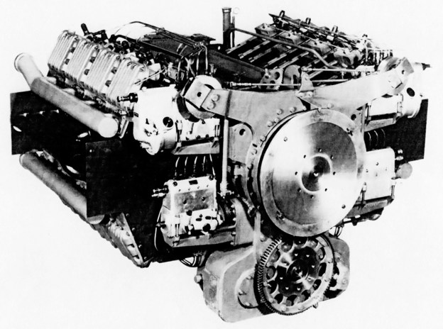
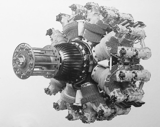
The Bristol Hydra was an odd radial engine utilizing two inline rows of eight cylinders. The engine suffered from vibration issues due to a lack of crankshaft support. Note the dual overhead camshafts for each front and rear cylinder pair.

Fedden and Bristol evaluated at least 28 engine designs to determine the best path forward for a multi-row engine. At the same time, Fedden was investigating a switch to using sleeve valves, but their development at Bristol had just begun. The multi-row engine would continue to use poppet valves. At the end of 1931, a 16-cylinder, air-cooled engine design was selected for development. This engine was called the Double Octagon or Hydra.

The Bristol Hydra was designed by Frank Owner in 1932, and the project was overseen by Fedden. The radial engine was very unusual in that it had an even number of cylinders for each row. Nearly all four-stroke radial engines have an odd number of cylinders per row so that every other cylinder can fire as the crankshaft turns. In addition, the Hydra’s cylinder rows were not staggered—the first and second rows were directly in line with each other. The “Double Octagon” name represented the engine’s configuration, in which the eight cylinders on each of the engine’s two rows formed an octagon. The name “Hydra” was given to the engine because of its numerous “heads” (cylinders).

Bristol Hydra side drawing Perkins

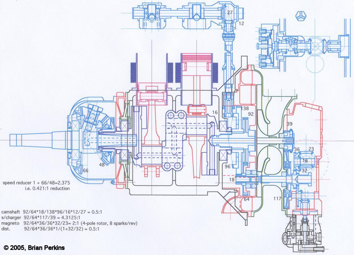
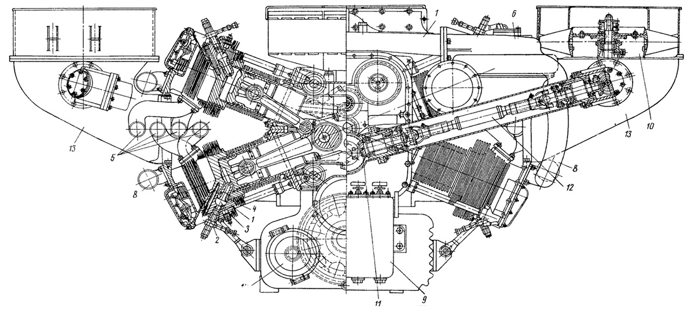
A sectional view of the Hydra created by Brian Perkins and based on a drawing found in the Bristol archives. The numbers in the drawing relate to the number of gear teeth. Note the unsupported crankshaft center section that joined the front and rear crankshaft sections. (Brain Perkins drawing via the Aircraft Engine Historical Society)

Unlike a traditional radial engine, the Hydra’s design resembled four V-4 engines mounted to a common crankcase and using a common crankshaft. In fact, a V-4 test engine was built to refine the Hydra’s cylinder and valve train design before a complete engine was built. The V-4 cylinder sections were mounted at 90-degree intervals around the crankcase, and their cylinders had a 45-degree bank angle. This configuration spaced all cylinder banks at 45-degree intervals. The V-4 cylinder sections had their exhaust ports located on the outer sides and their intake ports positioned in the Vee of each V-4 cylinder section. Two supercharger-fed intake manifolds delivered air to the Vee of each V-4 cylinder section, with each manifold servicing one front and rear cylinder. The engine’s supercharger turned at over four times crankshaft speed.

The Hydra used an aluminum cylinder that was machined all over with cooling fins. A steel barrel lined the inside of the cylinder. Each cylinder had one intake and one exhaust valve. Each front and rear cylinder formed a pair, and each cylinder pair had separate overhead camshafts that directly operated the intake and exhaust valves. At the rear of the cylinder pair, the exhaust camshaft was driven via beveled gears by a vertical shaft that was powered from the crankshaft by a gear set. A short cross shaft extended from the exhaust camshaft to power the intake camshaft. Each cylinder had two spark plugs.

Bristol Hydra 16-cylinder

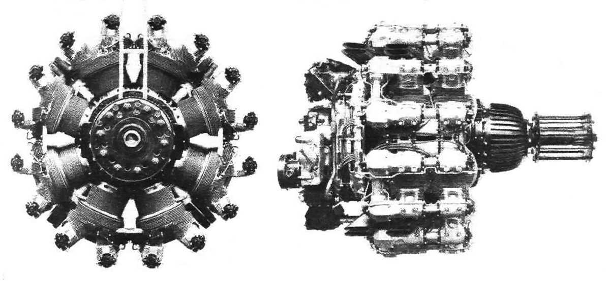
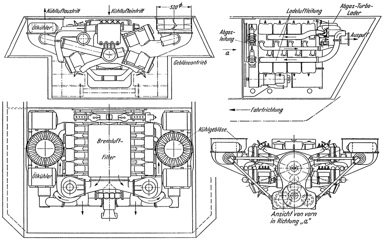
Front and side view of the Hydra. Note the exhaust stacks protruding slightly above the cylinders.

The engine’s crankshaft was built-up from three pieces. The center piece joined the front and rear sections via four clamping bolts. The crankshaft only had two main bearings and no center support. Single-piece master connecting rods were used. A bevel gear reduction at the front of the engine reduced the propeller speed to .42 times that of the crankshaft. The relatively high-level of gear reduction was needed because of the engine’s high operating speed.

The Hydra had a 5.0 in (127 mm) bore and stroke. The engine’s total displacement was 1,571 cu in (25.7 L). The Hydra had a 6 to 1 compression ratio and produced 870 hp (649 kW) on 75 octane fuel. On 87 octane fuel, the engine reportedly produced 1,020 hp (761 kW). The power outputs were achieved at 3,620 rpm, a very high speed for a radial engine. The engine was 46.5 in (1.18 m) in diameter, 57 in (1.45 m) long, and weighed approximately 1,500 lb (680 kg). With its unusual cylinder configuration, the Hydra had the following cylinder firing order: 1F, 2F, 7R, 4F, 1R, 6F, 3R, 8F, 5R, 6R, 3F, 8R, 5F, 2R, 7F, and 4R.

Bristol Hydra Hawker Harrier

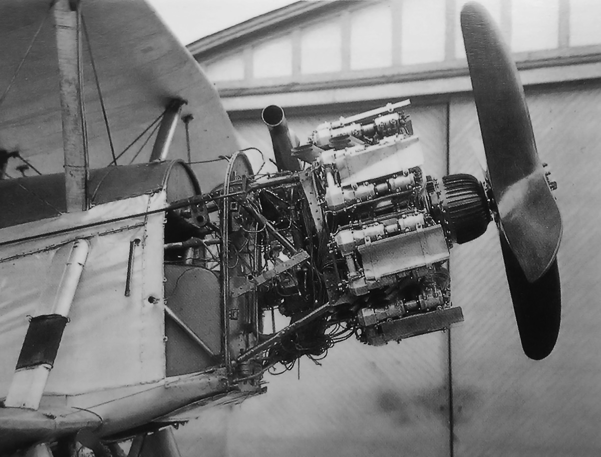
Hydra engine installed in the sole Hawker Harrier. Note the baffling on the engine. The four-blade test club propeller was fitted for ground runs.

The Hydra V-4 test engine underwent runs in mid-1932 and eventually produced around 190 hp (142 kW) with no cooling issues. A complete 16-cylinder Hydra was first run in 1933. Later that year, the engine was installed in the sole Hawker Harrier biplane bomber prototype, J8325. The engine’s configuration made installation very easy, and the intake Vees were baffled to improve cooling airflow.

The Hydra-powered Harrier encountered some oil leaks and ignition issues, but the main trouble was with excessive engine vibration. The lack of a center main bearing on the crankshaft caused the vibration issues, which could be quite severe at certain RPMs. The short stroke of the engine combined with a short crankshaft gave the designers the false hope that the center main bearing would not be needed. A redesign of the engine was required to cure the vibration issues.

Bristol Hydra Hawker Harrier side

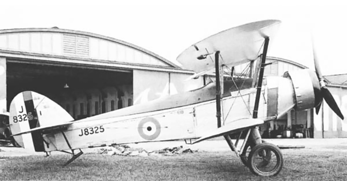
The Hydra-powered Harrier completely cowled and with its three-blade flight propeller. The aircraft was flown in this configuration during 1933, but engine vibration issues at critical RPMs limited the testing.

By 1934, the Mercury was approaching the 800 hp (597 kW) level, and the new nine-cylinder, 1,753 cu in (28.7 L) Pegasus was giving every indication that 900 hp (671 kW) was just around the corner. In addition, the sleeve valve, 1,519 cu in (24.9 L) Perseus engine had proved reliable and was producing around 700 hp (522 kW), and more ambitious sleeve valve engines were being designed. Rather than proceed with the Hydra and its double-octagon configuration, Bristol chose to develop its existing production engines and also focus on new sleeve valve engines.

The Hydra engine project was funded entirely by Bristol, although Fedden tried to get Air Ministry support. Only two Bristol Hydra engines were built; remarkably, both are reported to still exist. One is housed at the Sir Roy Fedden Heritage Centre, Bristol Branch of the Rolls-Royce Heritage Trust, in Bristol, United Kingdom. The other engine is stored at the Royal Air Force Museum London, located on the old Hendon Aerodrome.

Bristol Hydra display

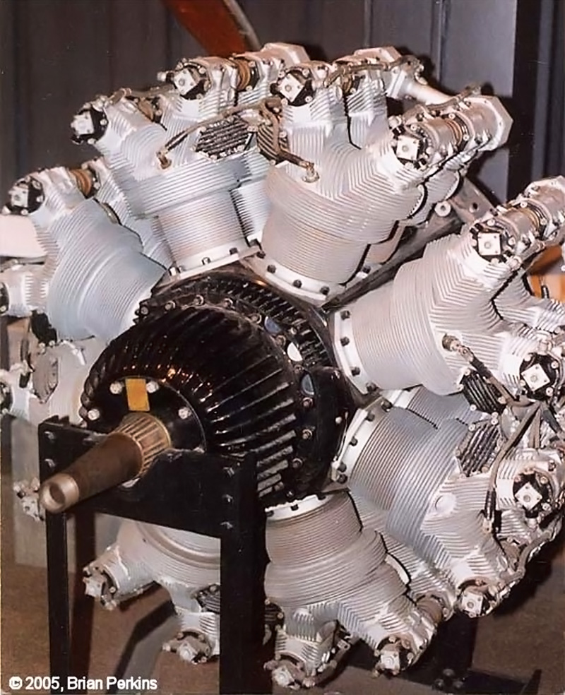
A preserved Bristol Hydra engine held by the Bristol Branch of the Rolls-Royce Heritage Trust. Note the extensive finning on the aluminum cylinders. (Brain Perkins image via the Aircraft Engine Historical Society)

Sources:
Fedden – the life of Sir Roy Fedden by Bill Gunston (1998)
British Piston Aero-Engines and their Aircraft by Alec Lumsden (2003)
An Account of Partnership – Industry, Government and the Aero Engine by George Bulman and edited by Mike Neale (2002)
– “My Wife Calls it an Obsession!!!! Part 2: Bristol Hydra” by Brian Perkins Torque Meter Volume 4, Number 2 (Spring 2005)
“The Future of the Air-Cooled Engine” Flight (25 February 1937)
http://www.enginehistory.org/ModelEngines/Perkins/Hydra/bristol_hydra.shtml

SGP Sla 16 X-16 front

SGP Sla 16 (Porsche Type 203) X-16 Tank Engine

By William Pearce

In 1943, Simmering-Graz-Pauker (SGP) in Vienna, Austria was tasked by the Heereswaffenamt (HWA, German Army Weapons Agency) to develop a new main tank engine for the Heer (German Army). The requested engine was an air-cooled diesel that would only require minor modifications to be interchangeable with the existing engine installed in various German tanks. The existing engine was the liquid-cooled Maybach HL230 V-12 that produced 690 hp at 3,000 rpm and displaced 1,409 cu in (23.1 L). However, reliability issues with the HL230 limited the engine to 2,500 rpm and 600 hp (447 kW). The demand for an air-cooled diesel was dictated by Adolf Hitler, and SGP was to work closely with Porsche GmbH to develop the new engine.

SGP Sla 16 X-16 front

Front view of the basic Simmering-Graz-Pauker Sla 16 engine without the airbox, turbochargers, or cooling fans. The intake manifolds and some baffling can be seen in the 45-degee Vee formed by the cylinders. Note that the intake ports are on the top of the cylinders.

Led by Ferdinand Porsche, the Porsche design and consulting firm had experience with air-cooled engines and took on the brunt of the preliminary design work for the new engine. Ferdinand Porsche had been discussing tanks and diesel tank engines with Hitler since 1942. Designed by Porsche’s Paul Netzker, the new engine was an X-16 layout consisting of four banks of four cylinders. The cylinder banks were spaced 135 degrees apart on the top and bottom and 45 degrees apart on the sides. The engine was issued Porsche designation Type 203 and SGP designation Sla 16 (which will be used for the remainder of this article).

The Simmering-Graz-Pauker Sla 16 was made of a sheet steel crankcase and used a single crankshaft with four master connecting rods. Three articulating connecting rods attached to each master rod. The cylinders were comprised of a substantially finned aluminum cylinder head screwed onto a finned, steel cylinder barrel. At the front of each cylinder bank was an injection pump that fed fuel to that bank’s cylinders. The fuel injector was positioned in the cylinder head and angled toward the 135-degree side of the cylinder. At the base of each cylinder bank was a camshaft positioned on the 135-degree side. The four camshafts were driven from the rear of the engine and operated the two valves per cylinder via pushrods and rockers. The intake and exhaust ports were located on the 45-degree side of the cylinders, with the intake port on the top of the cylinder.

SGP Sla 16 X-16 section

Transverse cross section of the Sla 16 illustrates the engine’s X configuration and the drive for the cooling fans. Note the master and articulated connecting rods and the four exhaust manifolds in the left side of the drawing.

Induction air was drawn in through a large filter placed above the engine. The air then flowed through twin turbochargers located at the engine’s rear. Two separate intake manifolds branched out from each turbocharger, with one manifold supplying the upper cylinder bank and the other manifold supplying the lower cylinder bank. The exhaust from two cylinders was paired in a single manifold so that each side of the engine had four exhaust manifolds leading to the turbocharger. The turbochargers were made by Brown Boveri and spun at a maximum of 28,000 rpm. The boost from the turbochargers was conservative at 7.3 psi (.5 bar).

To cool the engine, a fan was placed above and outside each of the two upper cylinder banks. The fans extracted warm air out from between the tight, 45-degree cylinder bank sections, which were closely baffled. As a result, cool air was drawn in through the cylinders’ cooling fins and into the 45-degree Vee. Each fan was driven via a beveled gear shaft that extended from the cooling fan to the rear of the engine. Here, an enclosed drive shaft with two universal joints and beveled gears took power from the crankshaft at the extreme rear of the engine and powered the shafts that led to the fans. The cooling fans were developed by FKFS (Forschungsinstitut für Kraftfahrwesen und Fahrzeugmotoren Stuttgart or Research Institute of Automotive Engineering and Vehicle Engines Stuttgart). The fans were 20.5 in (520 mm) in diameter and operated at 2.05 times crankshaft speed. Two oil coolers flanked each engine cooling fan.

SGP Sla 16 X-16 rear

Without all of the engine’s accessories, the drive for the cooling fans can be seen protruding from the back of the Sla 16 engine. The push rod tubes and fuel injectors are visible on the far cylinder bank. The four passageways in the rear baffle are for the exhaust manifolds.

Helical gears increased the speed of the Sla 16’s output shaft to 1.5 times crankshaft speed. The speed increase was needed because of the operating speed difference between the Sla 16 and the Maybach HL230. In order to be a direct replacement, the 2,000 rpm Sla 16 needed to have an output speed multiplier to match the 3,000 rpm HL230. Since the Sla 16’s crankshaft was in the middle of the engine’s X configuration, the step-up gears also lowered the output shaft to align with the existing transmission used with the V-12 HL230.

The Sla 16 had a 14.5 to 1 compression ratio, a 5.3 in (135 mm) bore, and a 6.3 in (160 mm) stroke. The engine’s total displacement was 2,236 cu in (36.6 L). The Sla 16 was forecasted to produce 750 hp (559 kW) at 2,000 rpm. With the cooling fans, the complete engine was approximately 5.5 ft (1.68 m) long, 8.2 ft (2.50 m) wide, and 3.8 ft (1.15 m) tall. The Sla 16 weighed 4,960 lb (2,250 kg).

By late 1943, a single-cylinder 140 cu in (2.3 L) test engine had been built and designated Type 192. The Type 192 engine passed a 48-hour test run on 6 November 1943. The single cylinder engine produced 47 hp (35 kW) at 2,100 rpm, which scaled to an output of 752 hp (561 kW) for the complete 16-cylinder engine. The listed output did not take into consideration the power needed to drive the cooling fans. With favorable results from the Type 192 tests, work moved forward on the full-size Sla 16 X-16 engine.

SGP Sla 16 X-16 fans rear

Rear view of the complete Sla 16. The airbox on the top of the engine fed air into the turbochargers via a bifurcated manifold. Note the oil coolers and cooling fans. The enclosed drive shafts for the cooling fans can been seen below the turbocharger exhaust outlets.

The first Sla 16 engine was tested in late 1944 and produced 770 hp (574 kW) at 2,200 rpm without the cooling fans. It took around 95 hp (71 kW) to drive the cooling fans, which reduced the engine’s output to 685 hp (511 kW). On 10 January 1945, two Sla 16 test engines had completed a combined 300 hours of test operation. Porsche’s involvement with the engine had essentially stopped by this time. Plans were made for Sla 16 production to start in June 1945 at the Steyr-Daimler-Puch factory in Austria. Steyr-Daimler-Puch was producing Daimler-Benz DB 603 engines (although the factory built DB 605s from October 1942 to October 1943), and production of the DB 603 would give way for the Sla 16. Some changes were incorporated into the Sla 16 production engines, such as the use of two fuel injection pumps rather than the four pumps used on the prototype engines. It is possible that the production engines carried the Porsche Type 220 designation. However, the Sla 16 engine never entered production because of the German surrender in May 1945.

A Sla 16 engine was reportedly installed in the chassis of the experimental Panzerjäger Tiger Ausf. B (Tank Hunter Tiger Variant B or Jagdtiger, Hunting Tiger) and underwent some feasibility tests. Initially, the lower cylinder banks ran hot, but modifications to the cooling fans and air baffles resolved the issue. In addition, a Panzerkampfwagen Tiger Ausf. B (Armored Fighting Vehicle Tiger Variant B), or Tiger II, was modified to accept a Sla 16 engine and waited for the engine’s installation. However, the installation was never completed. The engine was also proposed for the VK 45.02 P2 (Porsche Type 181C), which was never built. The majority of Sla 16 parts, tooling, and equipment were captured by the Soviet Union at the end of World War II.

SGP Sla 16 X-16 stand

The left image (engine inverted) shows the camshaft drives at the rear of the engine. In the center image (engine upright), the engine’s output can be seen below the crankshaft. The right image (engine almost inverted) displays the cylinder’s valves. The exhaust ports on the side of the cylinders are easily seen, while the intake ports on the top of the cylinders have been covered.

In late 1943, FKFS contemplated using the 140 cu in (2.3 L) cylinder from the Sla 16 as the starting point for a new tank engine to power the proposed Panzerkampfwagen Panther II. The FKFS engine consisted of two V-12 engines mounted 90-degrees apart on a common crankcase. The 24-cylinder engine would have displaced 3,354 cu in (55.0 L) and produced 1,100 hp (820 kW). Four engine-driven, FKFS cooling fans would have been installed, with two above each V-12 engine section. The FKFS 24-cylinder engine project did not progress beyond the drawing board, and the Panther II was never built.

A larger version of the X-16 engine was investigated under the Porsche Type 212 designation. This engine had a 5.9 in (150 mm) bore and a 6.7 in (170 mm) stroke. Total displacement of the Type 212 was 2,933 cu in (48 L), and the engine was forecasted to produce 1,500 hp (1,119 kW) at 2,500 rpm. A 183 cu in (3.0 L), single-cylinder test engine was evaluated as the Type 213, but it does not appear that the tests were completed or that a complete Type 212 engine was built. The Type 212 was proposed to power the Panzerkampfwagen VIII Maus (Porsche Type 205), but the engine was rejected by Albert Speer, the Minister of Armaments.

SGP Sla 16 X-16 test

The Sla 16 engine under test in late 1944 without cooling fans or turbochargers. However, the test equipment most likely provided forced induction.

Notes: Sources are split on the Porsche Type designation for the 750 hp (559 kW) Sla 16. Many refer to the engine as the Type 203, and just as many use Type 212. In addition, Type 180, 181, 192, and 220 are also used. Type 180 was a tank design (VK 45.02 P) that originally used Porsche’s Type 101 V-10 engine. Type 181 was the same tank reengined with the Sla 16 after the V-10 encountered problems. As mentioned in the article, Type 192 was a single-cylinder test engine for the Sla 16. Since Type 213 was a single-cylinder test engine for the larger X-16, it makes sense for the larger X-16 to be Type 212. This leaves Type 203 as the logical choice for the Sla 16. As stated in the article, Type 220 may have been the production version of the Sla 16.

Furthermore, a number of sources list the larger, 1,500 hp (1,119 kW) engine as an X-18. However, there can be no X-18 engine; to add up to a total of 18 cylinders, two banks would need to have five cylinders each, and two banks would need to have four cylinders each. Such an armament would be ill-advised. Most likely, “X-16” was either mistyped or misread as “X-18” on some scarce document captured at the end of World War II, and the misnomer stuck. However.

Lastly, the Porsche Type 181B (VK 45.02 P2) tank design was to be powered by two 16-cylinder engines. The 16-cylinder engine was an air-cooled diesel that produced 370 hp (276 kW) at 2,000 rpm. Reportedly, the design of this engine was a collaboration with Deutz. Some sources indicate the engine was a V-16, while others state it was an X-16. It is not clear whether the smaller 16-cylinder engine had anything in common with the Sla 16 or what its Type number was. The small 16-cylinder engine had a 4.3 in (110 mm) bore, a 5.1 in (130 mm) stroke, and a total displacement of 1,206 cu in (19.8 L). The small 16-cylinder engine was never built.

SGP Sla 16 X-16 general arrangement rear

General arrangement drawing of the Sla 16 engine.

Sources:
Professor Porsche’s Wars by Karl Ludvigsen (2014)
Der Panzer-Kampfwagen Tiger und seine Abarten by Walter J. Spielberger (1998)
AFV Weapons Profile: Elefant and Maus (+ E-100) by Walter J. Spielberger and John Milsom (October 1973)
Wunibald I. E. Kamm – Wegbereiter der modernen Kraftfahrtechnik by Jurgen Potthoff and Ingobert C. Schmid (2012)
Daimler-Benz in the Third Reich by Neil Gregor (1998)
https://vk.com/page-39215368_53036748
http://ftr.wot-news.com/2014/11/25/maus-engine-by-captiannemo/
http://www.alanhamby.com/maybach.shtml