By William Pearce
In early 1937, Hawker Aircraft Limited and the company’s chief designer, Sydney Camm, began to consider the next generation of fighter aircraft for the Royal Air Force. The British Air Ministry was also considering the future of fighter airframes as well as the incorporation of powerful, new engines under development—specifically the Napier Sabre H-24, the Rolls-Royce Vulture X-24, and the Bristol Centaurus 18-cylinder radial.
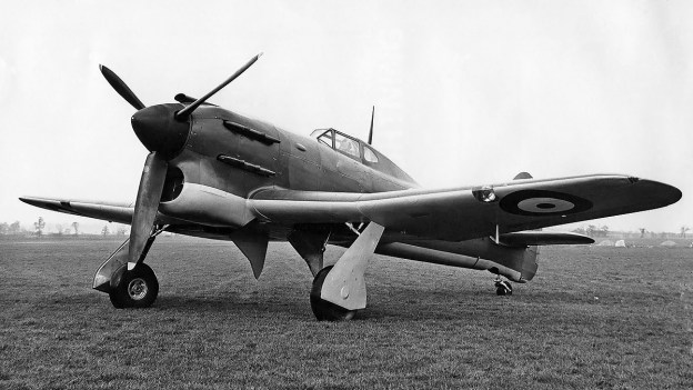
The first Hawker Tornado prototype P5219 in its original form with the belly radiator. The Vulture’s two rows of exhaust stacks are evident. The aircraft’s resemblance to the Hurricane is apparent.
In July 1937, Hawker proposed two Camm-designed aircraft—the N-type and the R-type, named for their respective Napier and Rolls-Royce powerplants. The Air Ministry told Hawker to wait until an official request was issued, which came in March 1938 in the form of Specification F.18/37 seeking a fighter capable of 400 mph (644 km/h) at 20,000 ft (6,096 m). Hawker was notified in August 1938 that they had won the design contest for Specification F.18/37, and two prototypes of each N-type and R-type were ordered. However, an official contract was not issued until December 1938. The N-type went on to become the Sabre-powered Hawker Typhoon, while the R-type became the Vulture-powered Hawker Tornado. The two Tornado prototypes were assigned serial numbers P5219 and P5224.
The Tornado was a single-engine fighter of all-metal construction with a conventional taildragger layout. The aircraft somewhat resembled an enlarged Hawker Hurricane. From the engine to just behind the cockpit, the fuselage consisted of a tubular frame covered with aluminum panels. The rear fuselage and tail were of monocoque construction. The pilot sat in an enclosed cockpit that was accessible via side entry doors. A fairing extended behind the cockpit and limited the pilot’s rearward vision.
The Tornado’s wing was mounted to the tubular frame of the center fuselage. Because of the Vulture’s installation, the wing was mounted to the fuselage about 3 in (76 mm) lower than on the Typhoon. The wing had two main spars and consisted of an inner and outer section. The inner section had a 1.0-degree anhedral and housed the inward-retracting main landing gear. The landing gear had a wide track of 13 ft 8 in (4.17 m). A 48 US gal (40 Imp gal / 182 L) fuel tank was located in each wing between the main gear leg well and the rear spar, and a 42 US gal (35 Imp gal / 159 L) fuel tank was located in the leading edge of each inner wing section. The Tornado’s total fuel capacity was 180 US gal (150 Imp gal / 682 L). Each outer wing section had a 5.5-degree dihedral and housed six Browning .303 machine guns with 500 rpg. The thick wing was originally designed for the possible installation of six 20 mm cannons, but this configuration was never tried. Each wing had a two-section, hydraulically actuated split flap and featured a large aileron. Except for the fabric-covered rudder, all control surfaces were covered with metal.
Another shot of the newly completed P5219 displays the aircraft’s original short tail. Note the opaque fairing behind the cockpit that blocked the pilot’s vision.
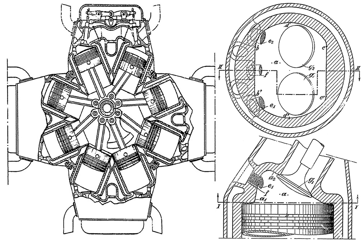
The Tornado’s Rolls-Royce Vulture II engine had 24 cylinders arranged in an X configuration. The engine was mounted to the forward part of the tubular fuselage frame and produced 1,760 hp (1,312 kW). Two rows of exhaust stacks protruded from each side of the engine’s cowling. A belly scoop between the main gear wells housed the engine’s coolant radiator and oil cooler. A door in the aft section of the scoop regulated temperatures. Two intakes between the belly scoop and the underside of the fuselage fed air to the engine’s carburetor. The engine turned a three-blade, constant-speed Rotol propeller that was 14 ft (4.27 m) in diameter.
The Hawker Tornado had a wingspan of 41 ft 11 in (12.78 m), a length of 32 ft 10 in (10.01 m), and a height of 14 ft 8 in (4.47 m). The aircraft had a top speed of 398 mph (641 km/h) at 23,000 ft (7,010 m) and stalling speeds of 82 mph (132 km/h) clean and 61 mph (98 km/h) with flaps and gear extended. The Tornado had an empty weight of 8,377 lb (3,800 kg) and a loaded weight of 10,668 lb (4,839 kg). The aircraft’s initial rate of climb was around 3,500 fpm (17.8 m/s), and its ceiling was 34,900 ft (10,638 m).
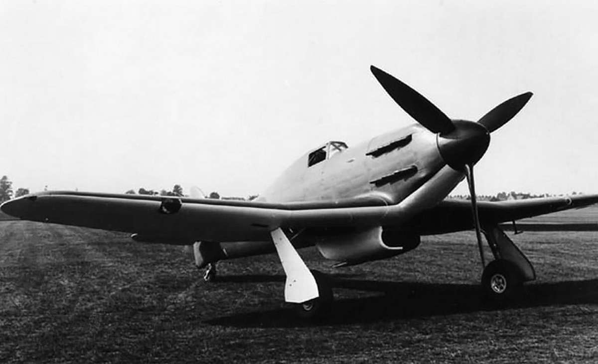
The second Tornado prototype P5224 with the chin radiator and windows behind the pilot to help improve vision. The aircraft now resembles a Typhoon, with which it shared many components.
The Tornado prototype P5219 was built at the experimental shop in Hawker’s Canbury Park Road facility in Kingston, but it was sent to Hawker’s new facility in Langley for final assembly in July 1939. The Vulture II engine was delivered in September 1939, and ground tests were started later that month. Piloted by Philip Lucas, P5219 made its first flight on 6 October 1939. During the preliminary flight tests in October and November, the aircraft achieved a speed of 370 mph (595 km/h) at 15,000 ft (4,572 m). However, the Tornado’s tail was lacking in surface area, and the rudder did not have sufficient authority to hold a straight course during takeoff and proved ineffective at speeds under 150 mph (241 km/h). Engine cooling was a constant issue, especially during ground operations. While in flight at higher speeds, turbulence from the wings disrupted airflow into the radiator, which impaired engine cooling. A new radiator was designed that would relocate the cooling system from its ventral position to a chin location under the engine. Metal was also found in the engine oil, indicating a possible issue with the Vulture’s bearings.
While the Vulture engine was undergoing maintenance, the Tornado airframe was modified with the new chin radiator and oil cooler, which shifted the aircraft’s appearance away from that of the Hurricane. In November 1939, an order for Hawker to produce 1,000 Tornados was placed. The contract was later changed to Typhoons, but then amended for 800 Typhoons and 200 Tornados, with the Tornados to be built by Avro due to Hawker’s production commitments of other aircraft, namely the Hurricane. Other Tornado production contracts were later issued, including 200 aircraft to be built by Cuncliffe-Owen and another 760 aircraft to be built by Avro. The revised Tornado took to the air on 6 December 1939, but Lucas reported that the aircraft was even more directionally unstable with the chin radiator. Performance tests in March 1940 indicated a top speed of 384 mph (618 km/h) at 20,500 ft (6,248 m), but the engine was not making full power. Various modifications were made to improve the aircraft’s stability. The exit of the radiator was extended 3 in (76 mm); the vertical stabilizer and rudder were enlarged in May 1940; and tailwheel doors were added in June 1940.

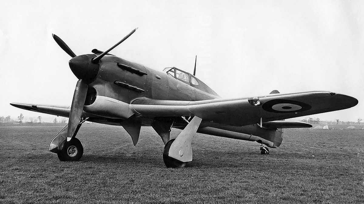
P5224 in flight displaying the aircraft’s aggressive appearance and enlarged tail. Note the carburetor intake atop the engine cowling.
With stability improved, P5219 was sent to Rolls-Royce’s flight-testing facility at Hucknall to improve the engine’s performance. The aircraft was returned to Langley in mid-July 1940 with a new engine and a new Rotol propeller that was 13 ft 2.5 in (4.02 m) in diameter. Performance flight testing continued, and on 27 July, the Tornado climbed to 20,000 ft (6,096 m) in 6 minutes and 36 seconds and achieved a speed of 396.5 mph (638.1 km/h) at 20,800 ft (6,340 m). On 31 July, the Vulture engine failed in flight, and the aircraft was damaged in the subsequent forced landing.
While P5219 was being repaired, the second Tornado prototype, P5224, was flown on 7 December 1940. Construction of the second prototype was delayed by other priority war work. P5224 was built from the start with the chin radiator and an enlarged tail. The aircraft also had the carburetor intake atop the engine cowling, inner gear doors to completely enclose the main gear, and side windows behind the cockpit to improve the pilot’s vision (which was still restricted). However, engine cooling was still an issue, as were excessive vibrations with the Vulture engine.
The repaired P5219 returned to active flight testing with a 1,980 hp (1,476 kW) Vulture V engine installed by March 1941, but the future of the Vulture engine was in doubt. P5224 suffered an engine failure on 21 March 1941, and its Vulture II was subsequently replaced by a Vulture V. P5224 first flew with the Vulture V on 11 June 1941. Around June 1941, Avro was instructed to halt work on producing the Tornado fighter, and the Tornado contracts were cancelled. The Vulture engine was stalled by Rolls-Royce so they could focus on the Merlin, and the Vulture was officially cancelled in October 1941. The Sabre-powered Typhoon fighter would be produced and take over resources previously allocated to the Tornado.
The first and only production Tornado, R7936, was used as a propeller testbed after its initial flight testing. The aircraft is seen here with Rotol contra-rotating propellers, which had a smaller diameter than the standard, single-rotation propellers used on the Tornado and Typhoon. Note that the aircraft did not have the windows behind the pilot like the second prototype.
P5219 continued flight testing with Hawker until at least April 1943, and the aircraft was scrapped in August 1943. P5224 was tested by the Aeroplane & Armament Experimental Establishment at Boscombe Down starting in October 1941. The aircraft was then delivered to the Royal Aircraft Establishment at Farnborough in December 1941. P5224 was scrapped in late 1944.
After the Tornado contracts were cancelled, construction of the first production Tornado, serial number R7936, was allowed to continue as well as components for two other examples that were nearing completion. R7936 was powered by a Vulture V engine and made its first flight on 29 August 1941, piloted by Lucas. In general, pilots that flew R7936 were impressed by its handling and performance. The aircraft recorded a speed of 402 mph (647 km) at 21,800 ft (6,645 m) and climbed to 20,000 ft (6,096 m) in 6 minutes and 54 seconds. With the Tornado program dead, R7936 was used as a testbed for Rotol and de Havilland contra-rotating propellers. Little information has been found on these tests, but the aircraft was delivered to Rolls-Royce in March 1942 for the installation of a Vulture engine with a contra-rotating gear reduction. The six-blade Rotol contra-rotating propeller was 11 ft 3 in (3.43 m) in diameter, and the aircraft was first flown with the unit on 11 August 1942. The de Havilland contra-rotating propellers were installed as early as December 1942. It appears R7936 continued with propeller tests until April 1944, when it was scrapped.

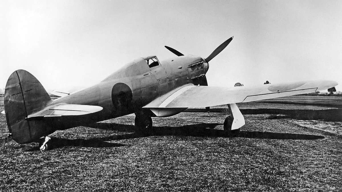
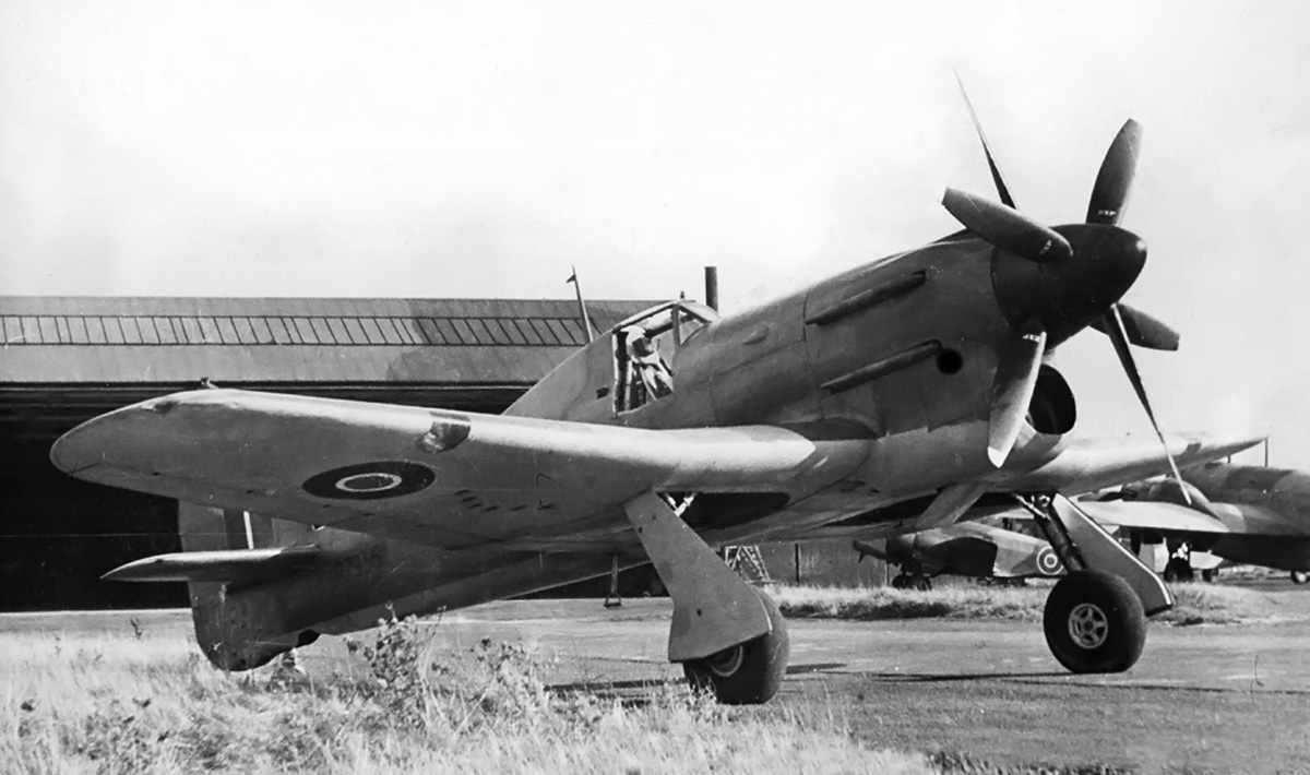
Typhoon HG641 was built to serve as a testbed for the Bristol Centaurus engine. Seen here with its original three-blade propeller, cowling, and single large exhaust manifold. The silhouette of the oil cooler can just be seen between the main landing gear.
From the first discussion with the Air Ministry before Specification F.18/37 was issued, Camm and Hawker had given some consideration to a Centaurus-powered Tornado, but little progress was undertaken beyond the preliminary design. With the Vulture and Sabre engines running into development issues by late 1940, more-serious consideration was given to installing a 2,210 hp (1,678 kW) Centaurus engine in a Tornado airframe. In September 1940, Hawker was given permission to proceed with the Centaurus-powered Tornado prototype, but the official contract was not issued until February 1941. Some work was also done on using a Wright R-3350 engine, but this design was dropped in June 1941.
The Centaurus Tornado was assigned serial number HG641. The aircraft was built by Hawker at Langley using components from uncompleted Tornado production airframes and a new center fuselage. The Centaurus engine turned a 12 ft 9 in (3.89 m) diameter, three-blade, Rotol propeller and was covered by a conventional cowling. Exhaust from the engine was expelled via a single manifold protruding from the cowling under the left side of the engine. An oil cooler was mounted between the wells for the main landing gear. The air-cooled radial reduced the aircraft’s weight by about 350 lb (159 kg). Lucas took the Centaurus Tornado up for its first flight on 23 October 1941.
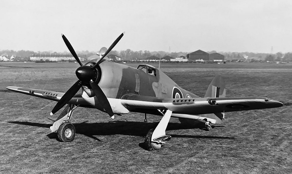
HG641 with the new four-blade propeller and revised cowling. The oil cooler was located in the large duct under the engine.
Initial flight tests of HG641 indicated that airflow through the oil cooler was not efficient and led to the engine running near its upper temperature limit. Even so, a speed of 378 mph (608 km/h) was recorded at 20,000 ft (6,096 m). The oil cooler was modified, and testing continued until December 1941. At that time, the aircraft was modified to improve the installation of the engine package, including exhaust and oil cooler. The cowling was revised, and a new oil cooler duct was faired into the lower cowling. Two exhaust stacks were incorporated into the left and right sides of the fairing. A four-blade propeller, also 12 ft 9 in (3.89 m) diameter, was installed, and the modified Centaurus Tornado took its first flight on 23 December 1942, piloted by Lucas. Cooling was improved, and the aircraft achieved 403 mph (649 km/h) at 22,000 ft (6,706 m) and had a ceiling of 32,800 ft (9,997 m). In February 1943, the aircraft was transferred to Bristol’s facility in Filton, where a speed of 412 mph (663 km/h) at 18,000 ft (5,486 m) was reportedly recorded. The Centaurus Tornado continued engine testing until August 1944, when the aircraft was scrapped.
The testing of Tornado aircraft provided information for developing the Typhoon fighter, contra-rotating propellers, and the Bristol Centaurus engine, which was particularly helpful when applied to the Centaurus-powered Hawker Tempest II fighter. Although the Tornado has been mostly forgotten, both the Typhoon and the Tempest served with distinction during World War II.
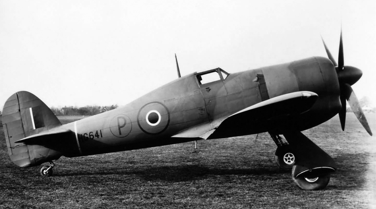
Side view of HG641 with the new cowling. The aircraft did not have the windows behind the pilot and used hinged doors on the landing gear to completely conceal the main wheels. This was also tried on the prototypes before switching to a separate inner door.
Sources:
– The Hawker Typhoon and Tempest by Francis K. Mason (1988)
– Hawker Typhoon, Tempest and Sea Fury by Kev Darling (2003)
– British Experimental Combat Aircraft of World War II by Tony Buttler (2012)
– Fighters Volume Two by William Green (1964)
– Hawker Typhoon and Tempest: A Formidable Pair by Philip Birtles (2018)
– Aircraft of the Fighting Powers Volume V by H. J. Cooper and O. G. Thetford (1944)
– The Secret Years: Flight Testing at Boscombe Down 1939 – 1945 by Tim Mason (1998)
– Hawker Aircraft since 1920 by Francis K. Mason (1991)