Category Archives: Aircraft Engines

Arsenal 24H rear

Arsenal 24H and 24H Tandem Aircraft Engines

By William Pearce

In occupied France during World War II, the state-run manufacturer Arsenal de l’Aéronautique (Arsenal) was tasked with building the German Junkers Jumo 213 engine. The Jumo 213 was a liquid-cooled, inverted V-12 engine that displaced 2,135 cu in (35.0 L) and produced 1,750 hp at 3,250 rpm. After the war, Arsenal continued to develop the Jumo 213 and manufactured a 2,300 hp variant as the Arsenal 12H.

Arsenal 24H front 2

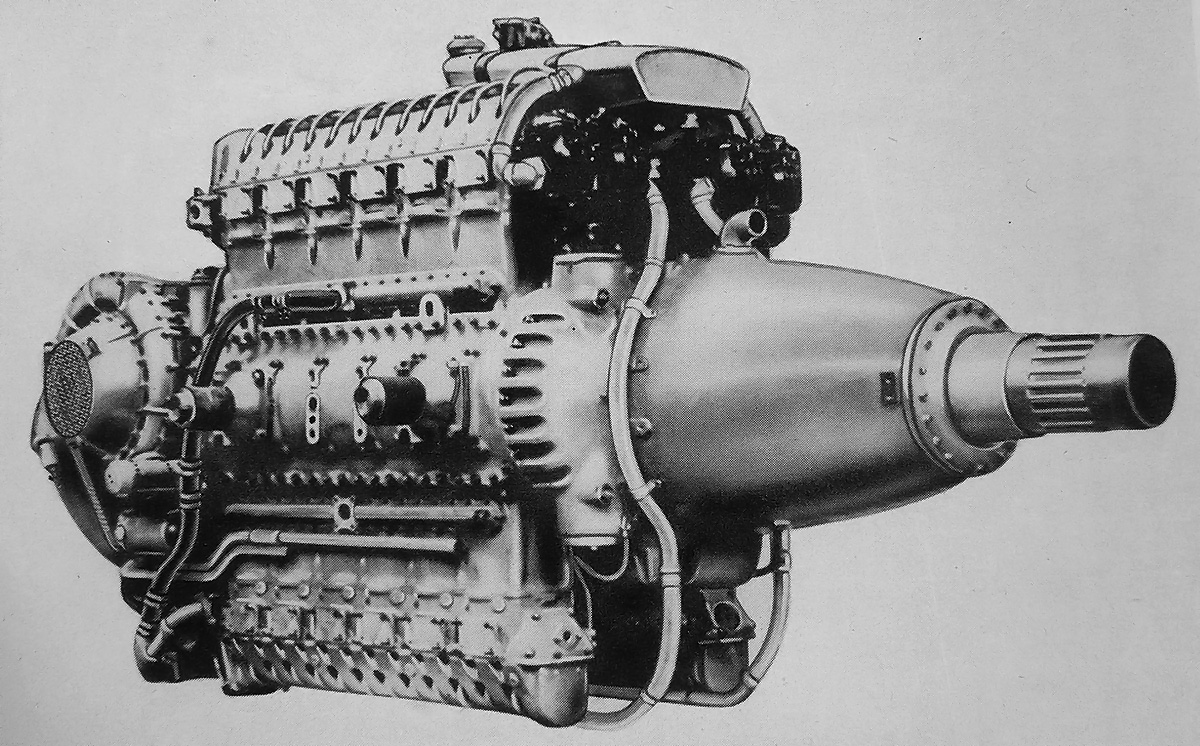
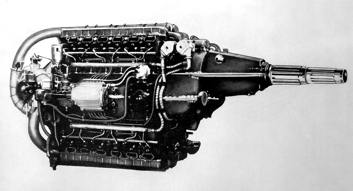
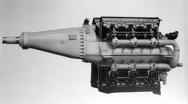
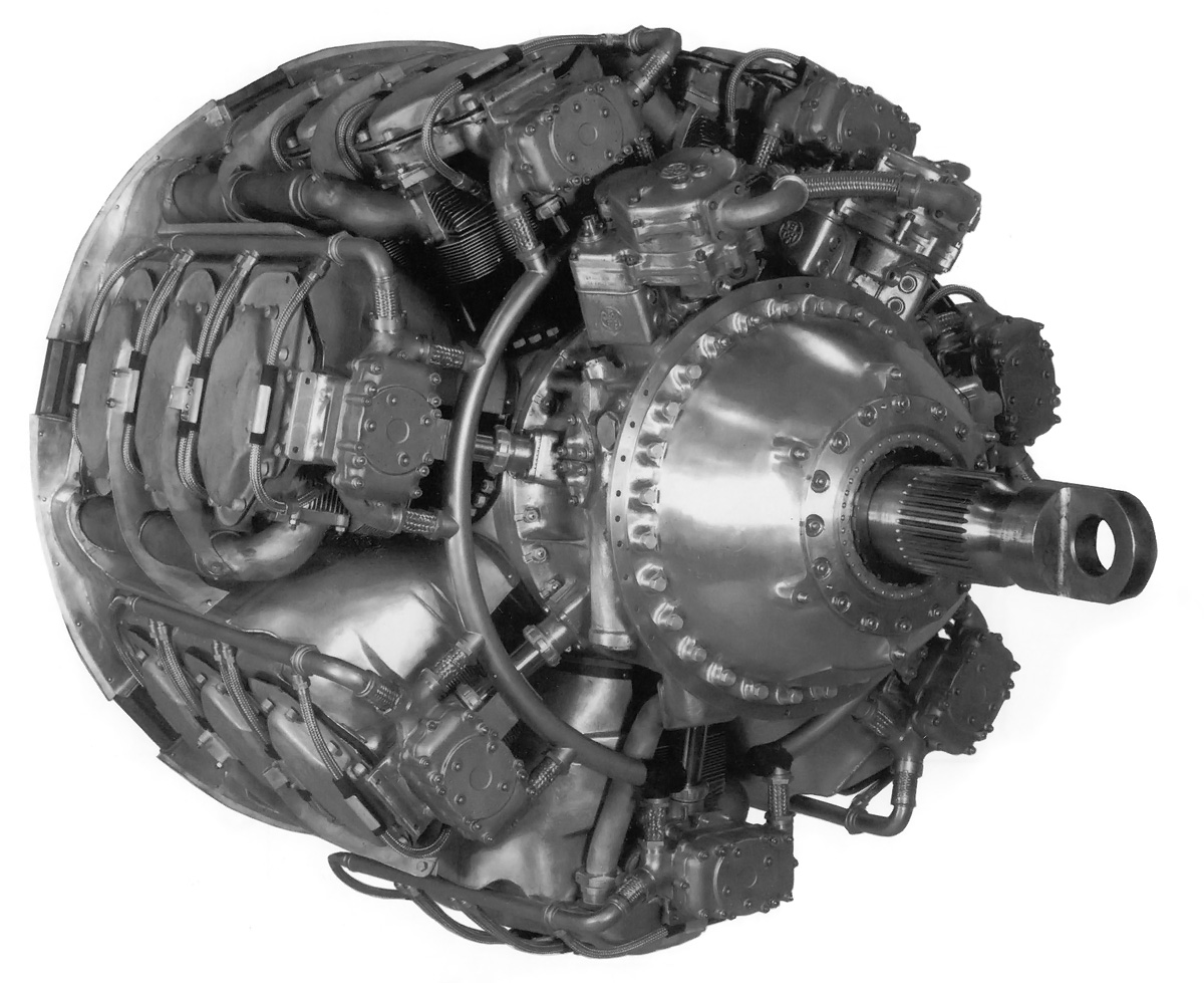
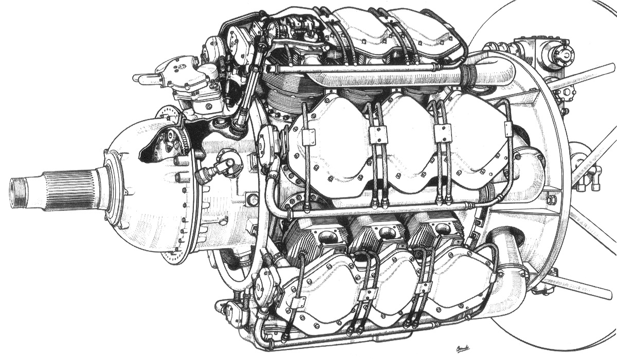
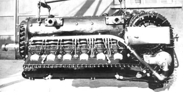
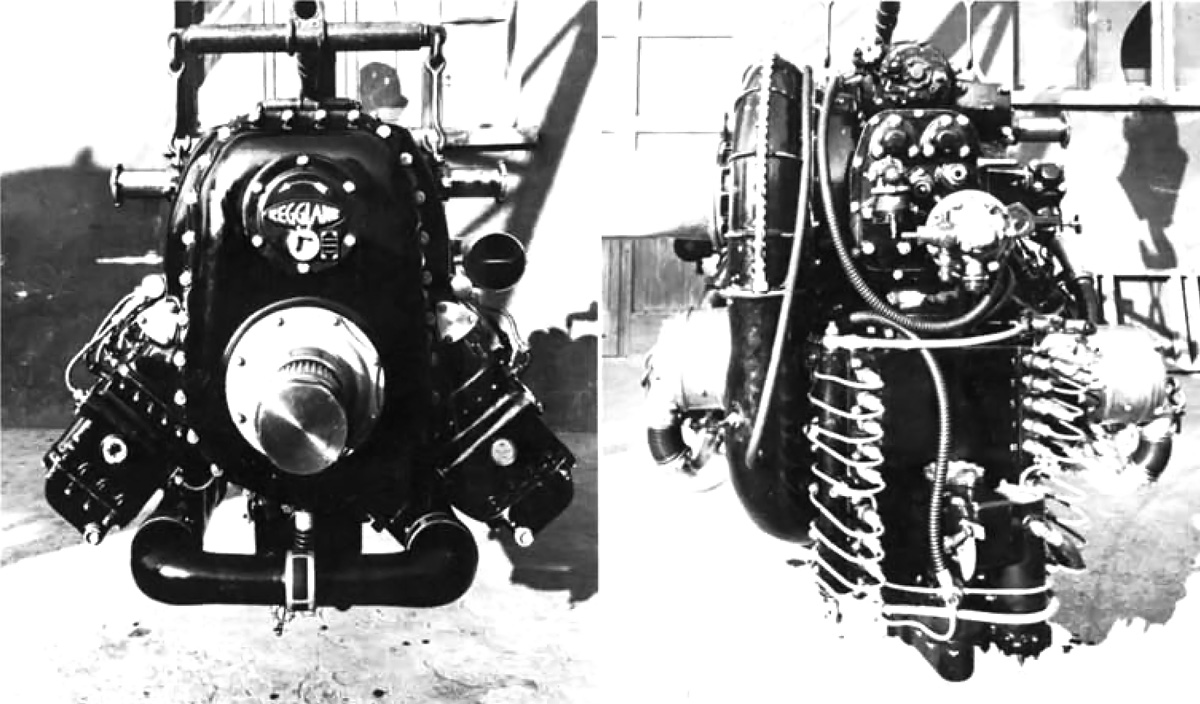
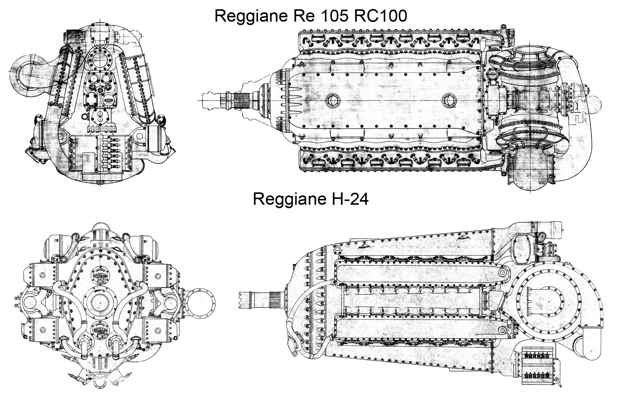
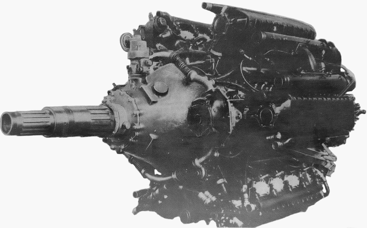
The Arsenal 24H was a 4,000 hp (2,983 kW), 24-cylinder engine that utilized many components originally designed for the Junkers Jumo 213 V-12. Note the centerline location of the single rotation propeller shaft.

During the war, Junkers contemplated building the Jumo 212, which was an H-24 engine utilizing many Jumo 213 components. While the Jumo 212 was not built, it was designed along the same lines as the Hispano-Suiza 24Y and 24Z engines. It is not known if Arsenal was inspired by the Jumo 212 or the Hispano-Suiza H-24 engines, but they created their own H-24 engine based on parts from the Arsenal 12H (which was originally based on the Jumo 213). Arsenal’s 24-cylinder engine was known as the 24H.

The Arsenal 24H was a vertical H engine with two cylinder banks mounted above the crankcase and two cylinder banks below. The two-piece aluminum crankcase was split vertically at its center. Covers on each side of the crankcase allowed access to the engine’s internals. While the cylinder blocks of the 12H were cast integral with its crankcase, the 24H used aluminum cylinder blocks that were separate. The detachable aluminum cylinder head featured two intake valves and one exhaust valve per cylinder. The valves for each cylinder bank were actuated by a single overhead camshaft driven by a vertical shaft at the rear of the engine.

Arsenal 24H side

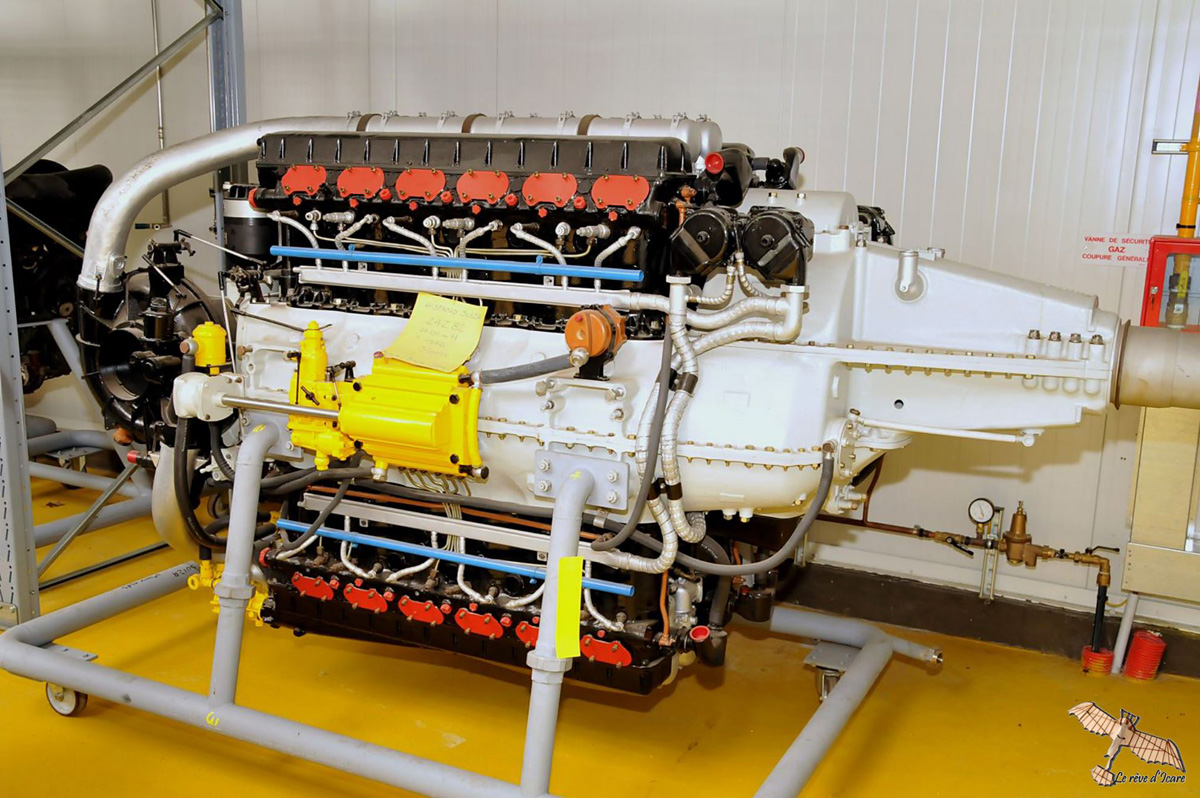
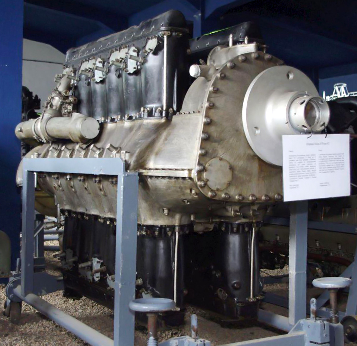
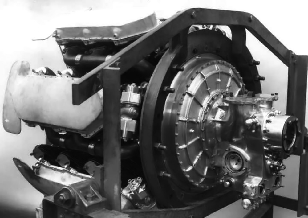
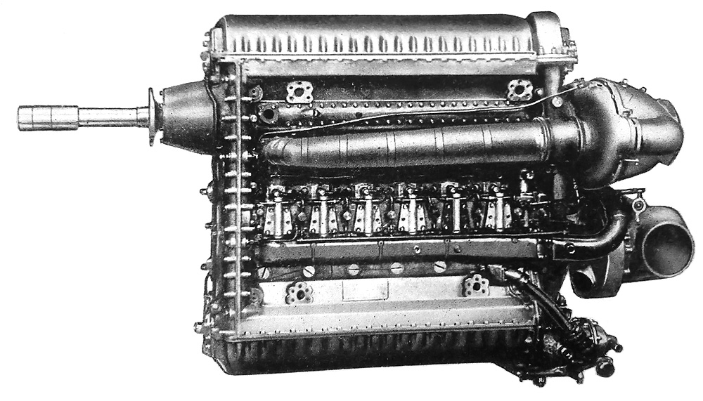
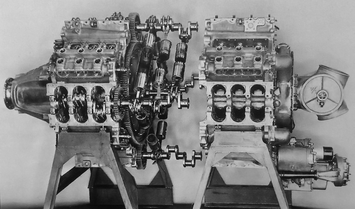
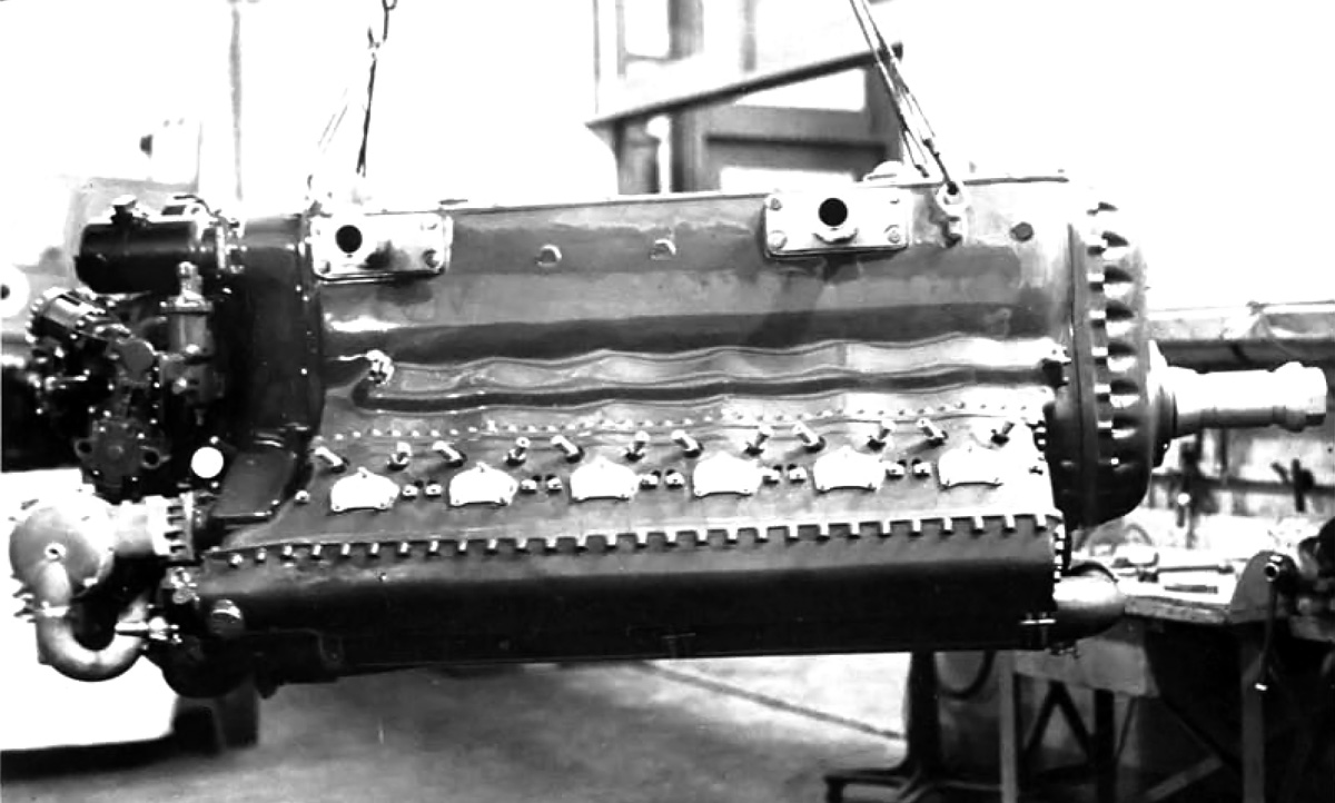
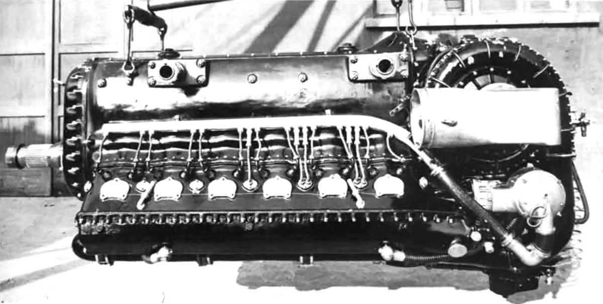
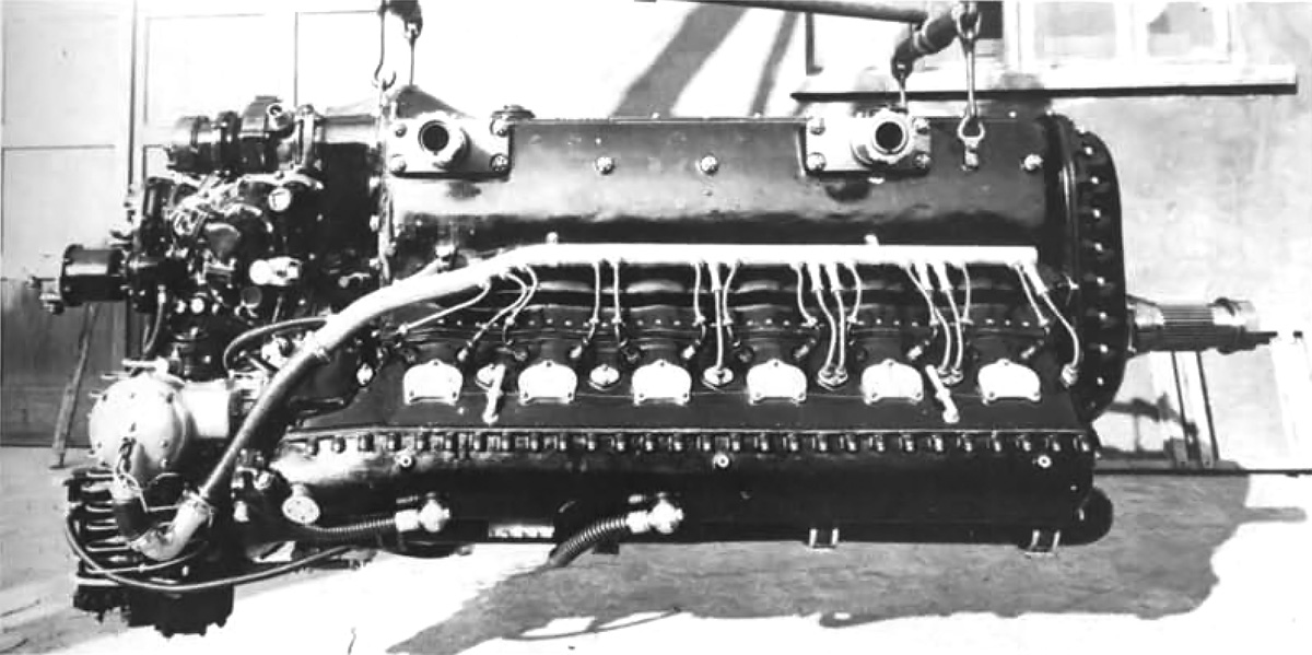
Unlike the Jumo 213, the cylinder blocks of the 24H were detachable and not cast integral with the crankcase. Note the magnetos mounted atop the gear reduction housing. The fuel injection pumps are just visible above the top valve cover and and below the bottom valve cover.

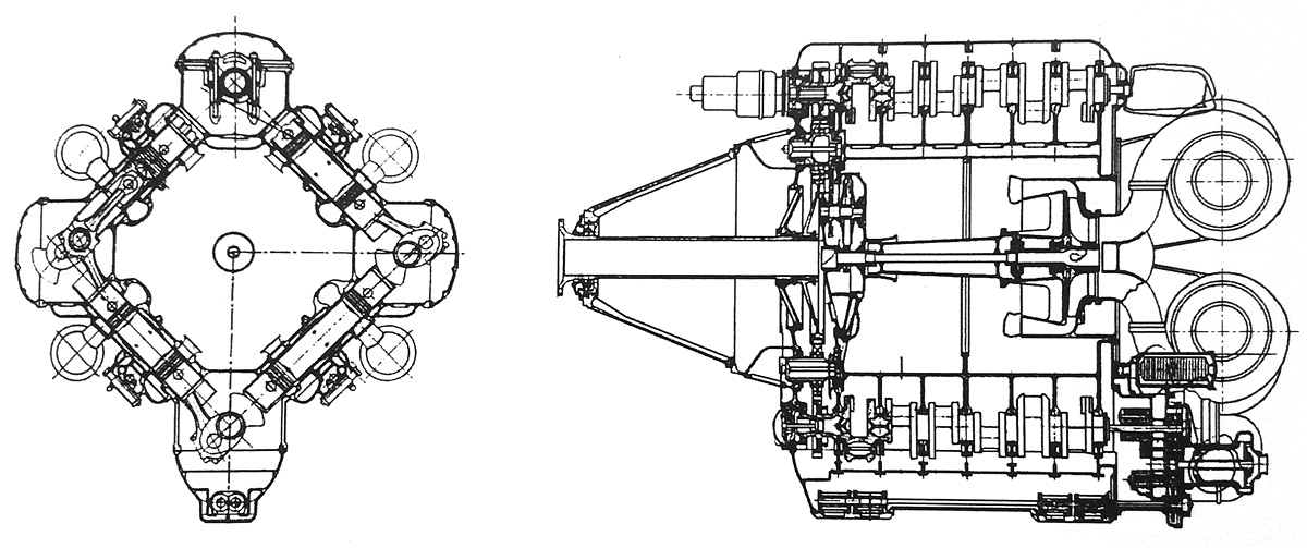
Inside the crankcase were two crankshafts with enough horizontal separation to allow a shaft to pass between them. This feature would allow engines to be coupled in tandem. Each crankshaft served an upper and lower cylinder bank pair. The crankshafts had six throws and were supported by seven main bearings. Pistons with a compression ratio of 6.5 to 1 were attached to the crankshafts by fork-and-blade connecting rods.

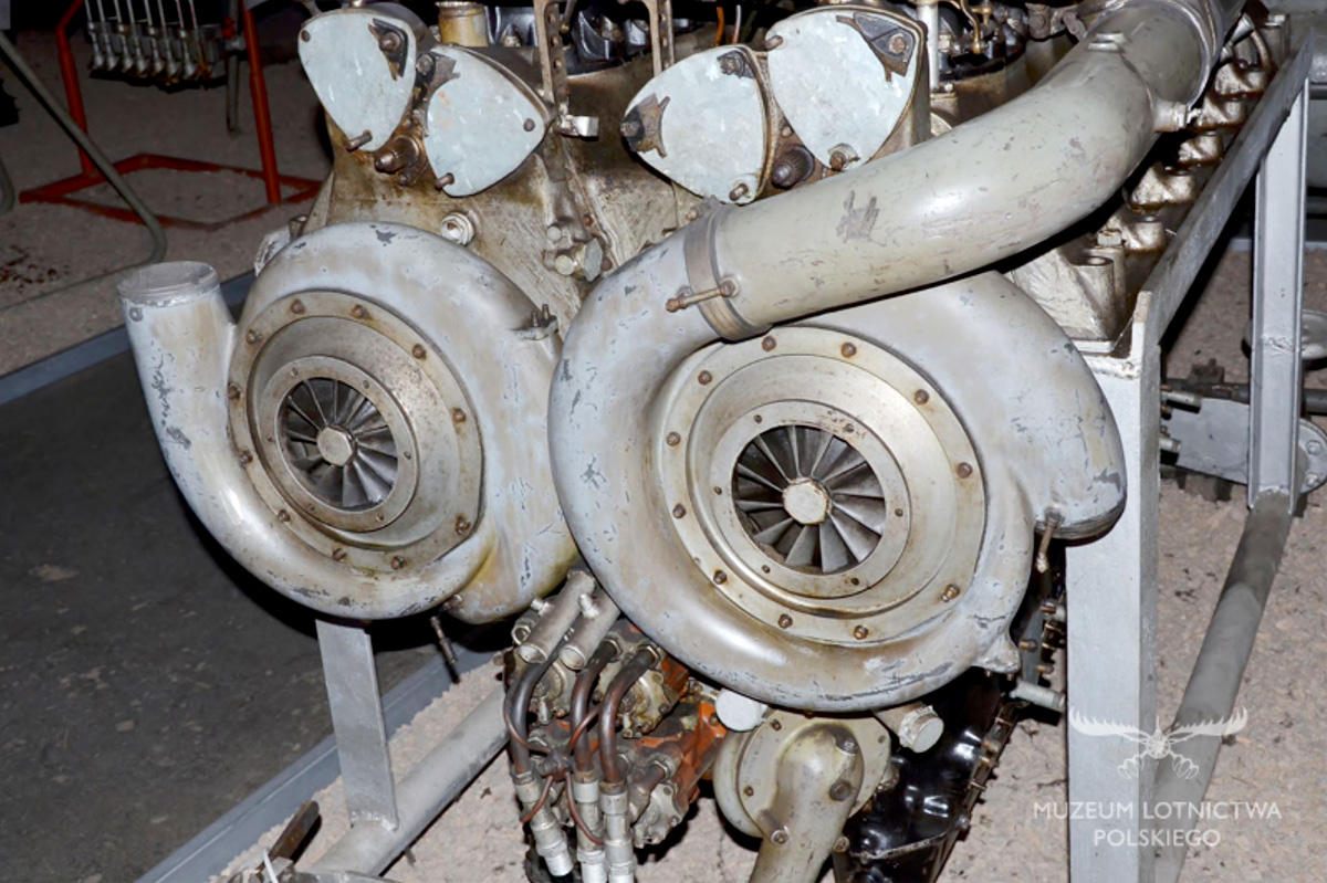
Two single-stage, two-speed superchargers were at the rear of the engine and driven by a cross-shaft from the engine’s accessory section. The superchargers had automatic boost and speed control with a low speed of 6.90 times crankshaft speed and a high speed of 9.41 times crankshaft speed. The left supercharger supplied air to the upper cylinder banks, and the right supercharger supplied air to the lower cylinder banks. The intake manifolds incorporated an aftercooler and were situated between their respective cylinder banks. A fuel injection pump was positioned between the cylinder banks and above the intake manifold. The 24H engine also utilized water injection.

Arsenal 24H rear

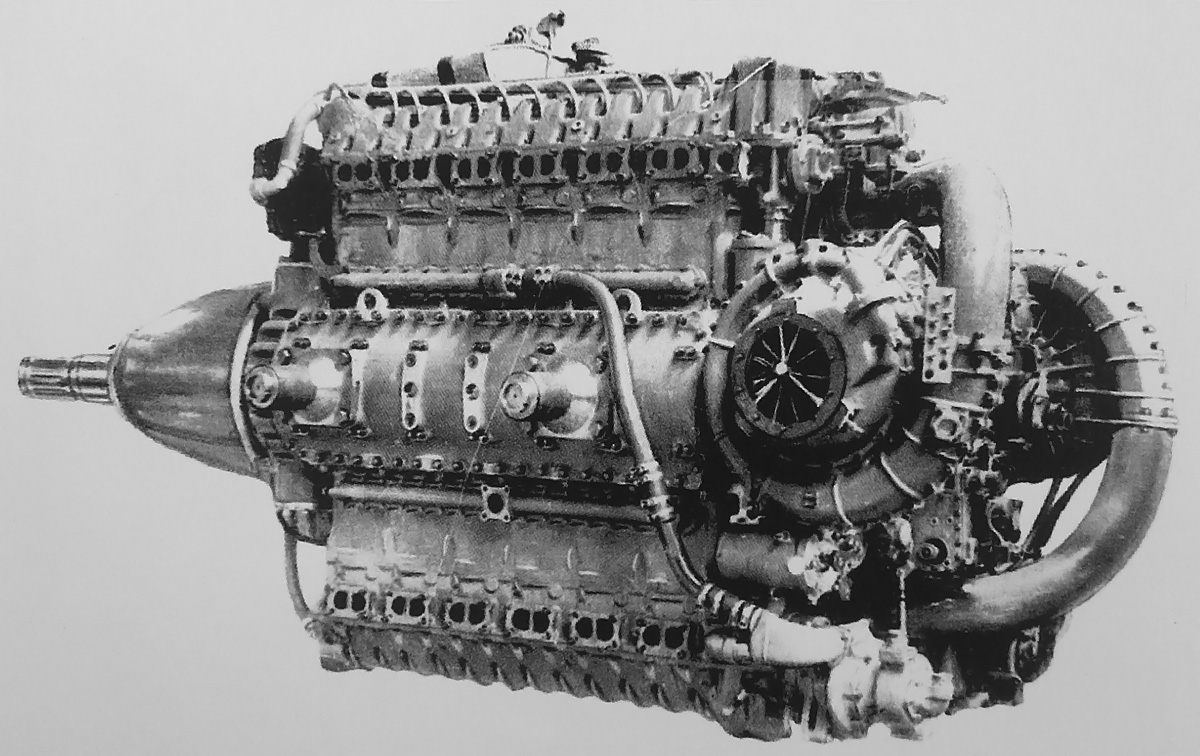
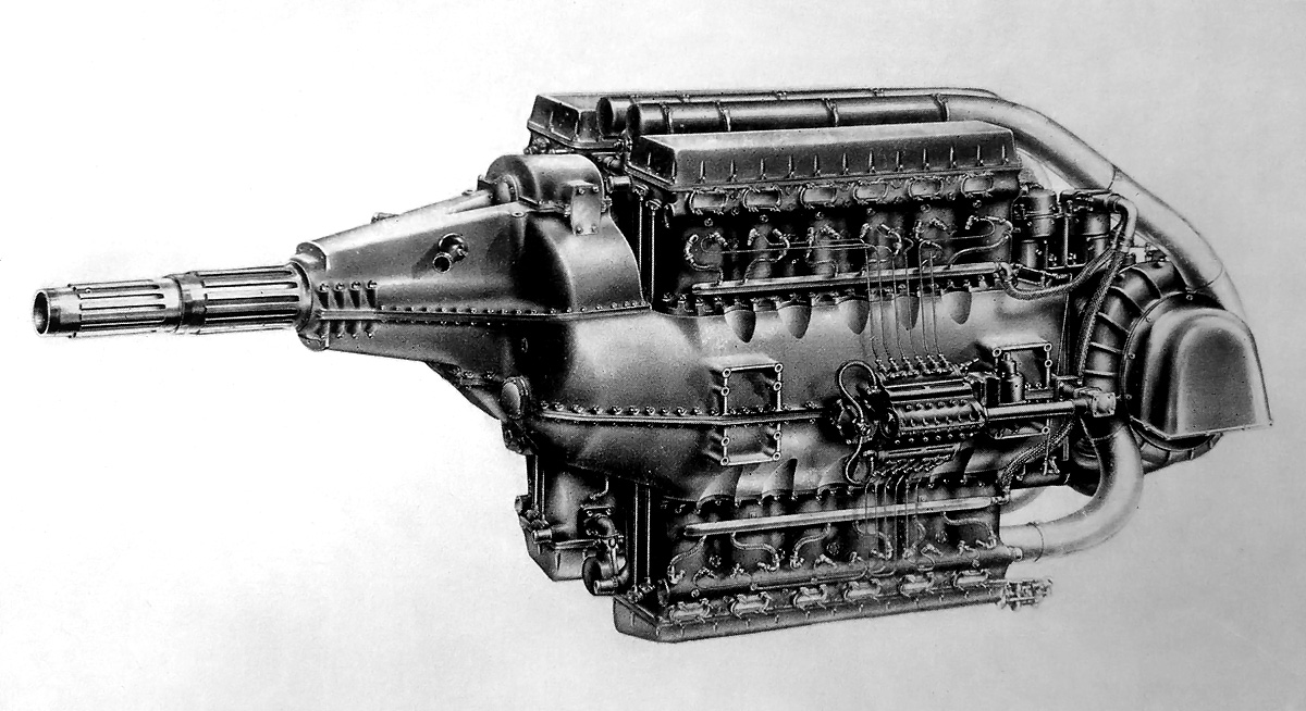
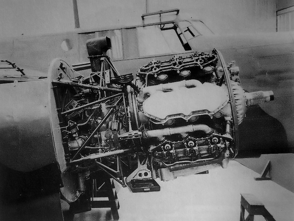
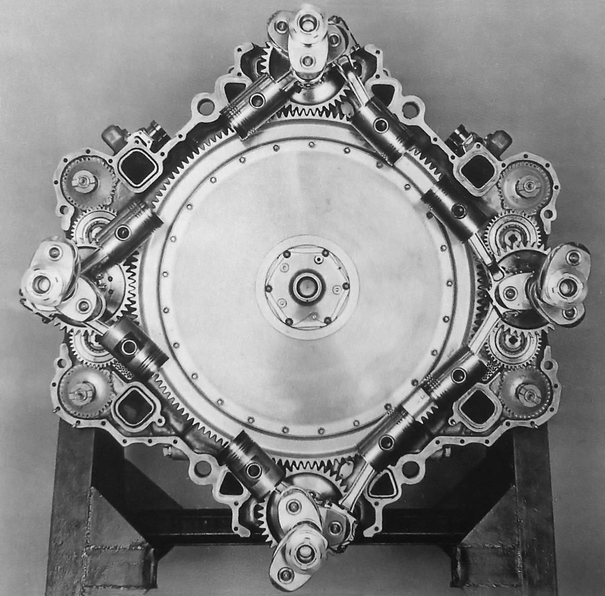
On the 24H, the left supercharger fed air to the upper cylinder banks, and the right supercharger fed air to the lower cylinder banks. Note the large engine mounts on the side of the crankcase.

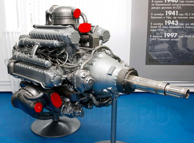
Each cylinder had two spark plugs which were positioned between the two intake valves and the single exhaust valve. The spark plugs were fired by two magnetos positioned at the front of the engine and above the propeller gear reduction housing. The propeller shaft was located on the engine’s centerline and incorporated a .4165 to 1 gear reduction. Although a contra-rotating gear reduction was designed, it is unclear if the unit was ever built, as all available images of the 24H show a single rotation propeller. The 24H and 12H shared cylinder heads, valve trains, most internal components, and many accessories, such as superchargers, fuel pumps, and magnetos.

The Arsenal 24H had a 5.91 in (150 mm) bore and a 6.50 in (165 mm) stroke. The engine’s total displacement was 4,270 cu in (69.98 L). With water injection and over-boosted at 11.0 psi (.76 bar), the 24H produced 4,000 hp (2,983 kW) at 3,250 rpm for takeoff. Without water injection, the 24H produced 3,500 hp (2,610 kW) at 3,250 rpm with 7.8 psi (.54 bar) of boost. The engine’s normal rating with low-speed supercharging was 3,200 hp (2,386 kW) at 3,000 rpm at 7,218 ft (2,200 m). With high-speed supercharging, the 24H had a normal rating of 3,000 hp (2,227 kW) at 3,000 rpm at 18,373 ft (5,600 m). The engine’s cruising power at 2,400 rpm was 2,200 hp (1,641 kW) at 9,843 ft (3,000 m) with low-speed supercharging and 2,000 hp (1,491 kW) at 17,060 ft (5,200 m) with high-speed supercharging. The 24H had a specific fuel consumption of .44 lb/hp/h (268 g/kW/h). The engine was 9.91 ft (3.02 m) long, 3.94 ft (1.20 m) wide, 4.92 ft (1.50 m) tall, and weighed 4,079 lb (1,850 kg).

Arsenal 24H SE 161 Languedoc cowling

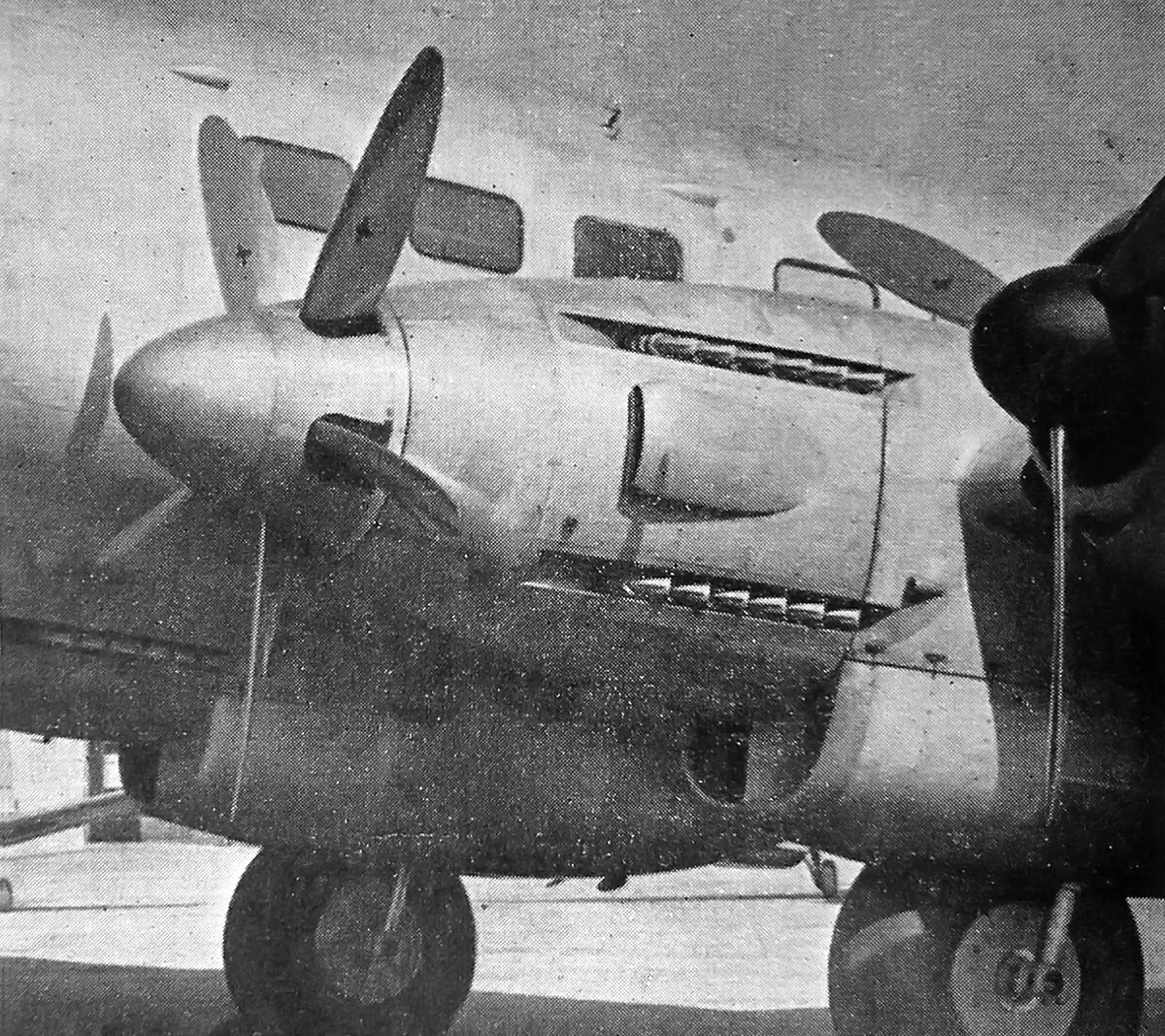
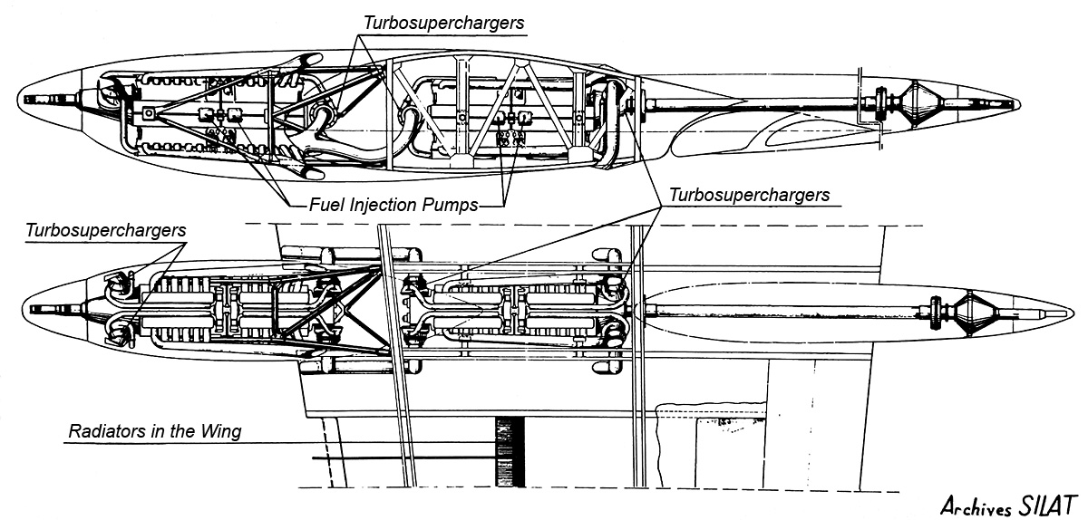
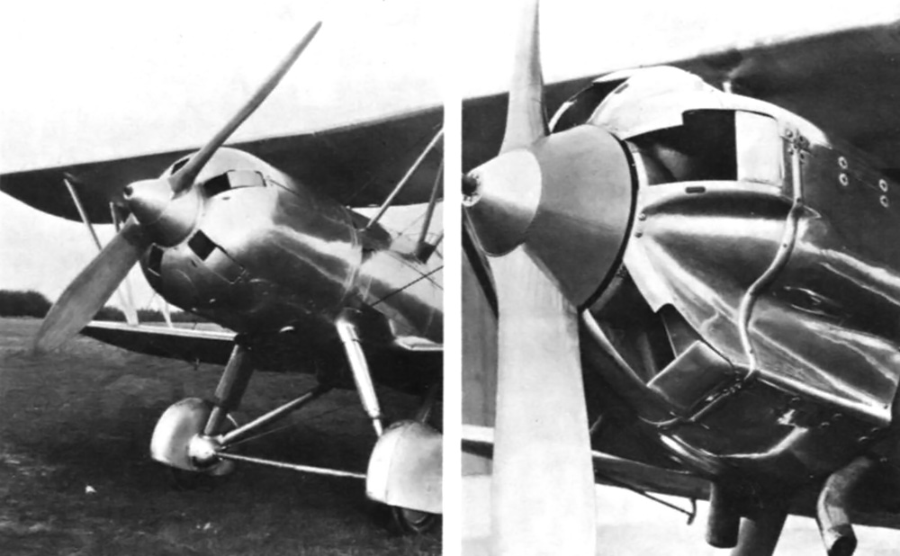
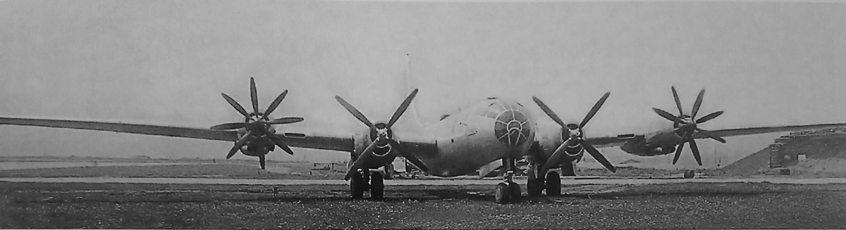
Two 24H engines were installed in the inner positions on a Sud-Est SE 161 Languedoc. The tight cowling cannot hide the size of the large the 24H engine. Note the large radiator housing behind the engine. The lower exhaust row of the second 24H engine can be seen on the left side of the photo.

Detail design work of the 24H started in December 1945. By April 1946, the crankcase casting had been made and delivered to Arsenal. The engine was assembled in Arsenal’s factory in Châtillon (near Paris), France and was first run in May 1946. In November 1946, the 24H was exhibited at the Salon de l’Aéronautique (Air Show) in Paris. Issues with the Hispano-Suiza 24Z resulted in the Arsenal 24H being selected for the SNCASE (Sud-Est) SE 580 fighter. However, the SE 580 project was abandoned in 1947, and it does not appear that an Arsenal engine was ever installed. At least three 24H prototypes were built and run for a total of over 1,600 hours. The engine’s predicted performance of 4,000 hp (2,983 kW) was achieved on the test stand.

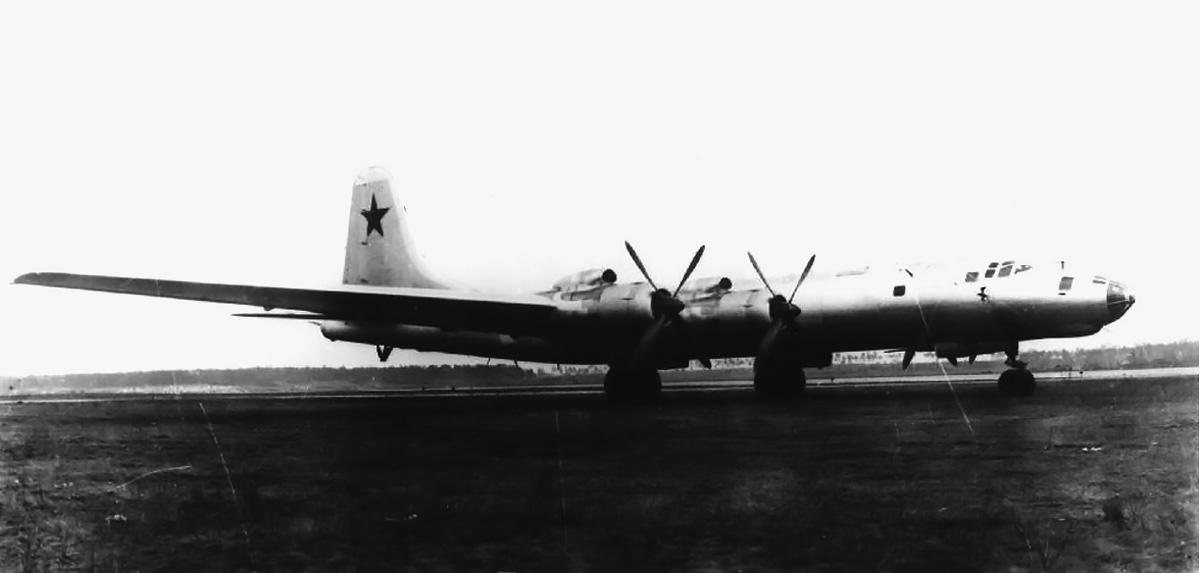
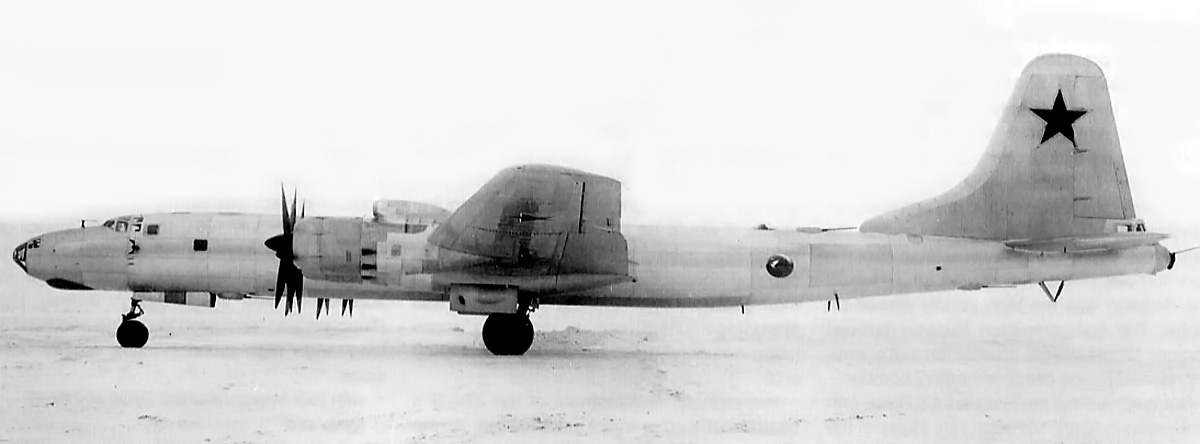
For flight testing, two 24H engines replaced the inner Pratt & Whitney R-1830 engines on a SNCASE (Sud-Est) SE 161/P7 Languedoc four-engine airliner. The engines were fitted with 10.5 ft (3.2m) diameter, metal, fully adjustable, five-blade propellers built by Ratier. The SE 161/P7 Languedoc with its 24H engines was flown for the first time in 1948. The engines performed well, but the relatively small propellers could not convert all of the 24H’s 4,000 hp (2,983 kW) to thrust. By the time the 24H had flown, the era of large piston aircraft engines was near its end. While the 24H was proposed for a few transports and flying boats (including eight engines used in the Latécorère Laté 182 and 184), new aircraft being built were designed with jet engines. There was no longer a need for a 4,000 hp (2,983 kW) engine, and the 24H was cancelled in 1950.

Arsenal 24H SE 161 Languedoc

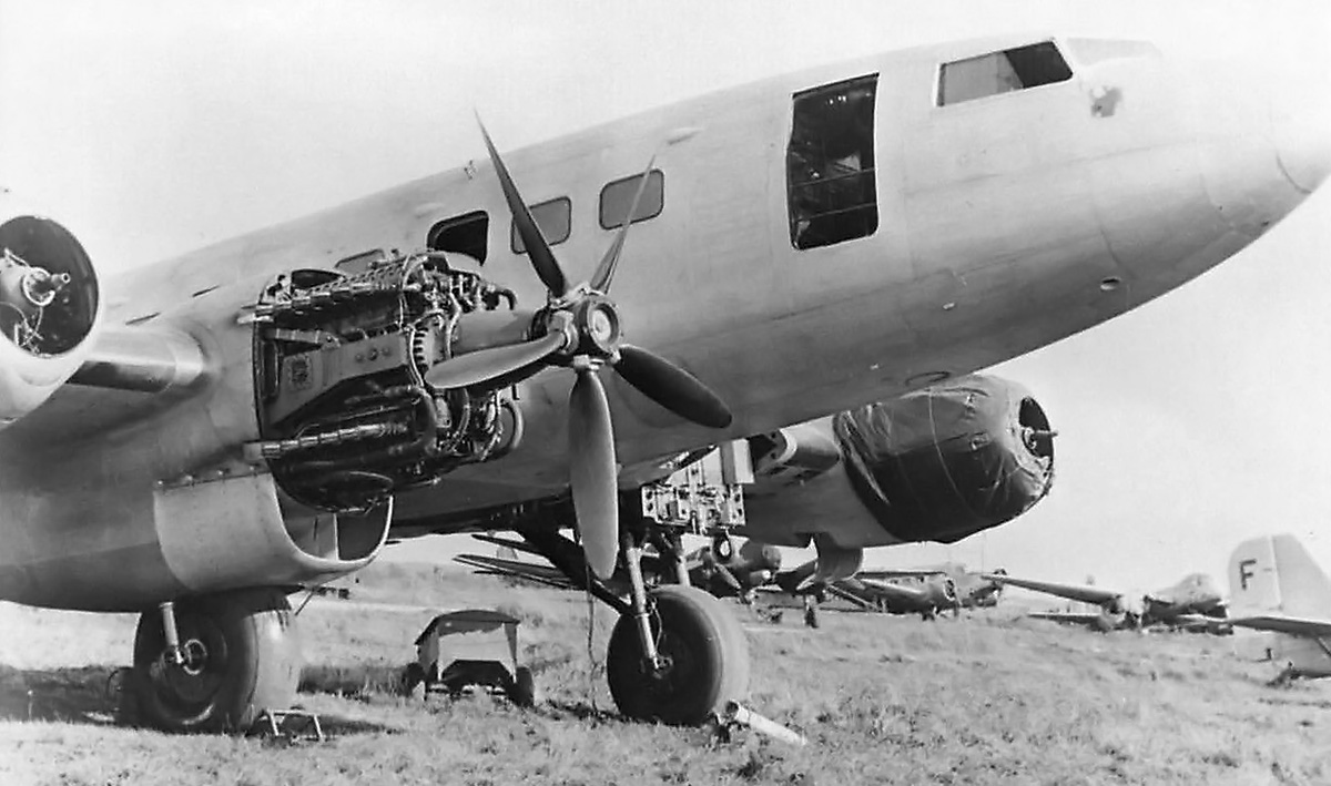
The SE 161 Languedoc appearing in a semi-abandoned state. One of the 24H engines has been removed, but exhaust stains are still present behind the remaining engine. Perhaps the aircraft was just used for ground runs when this photo was taken. Note the German aircraft in the background.

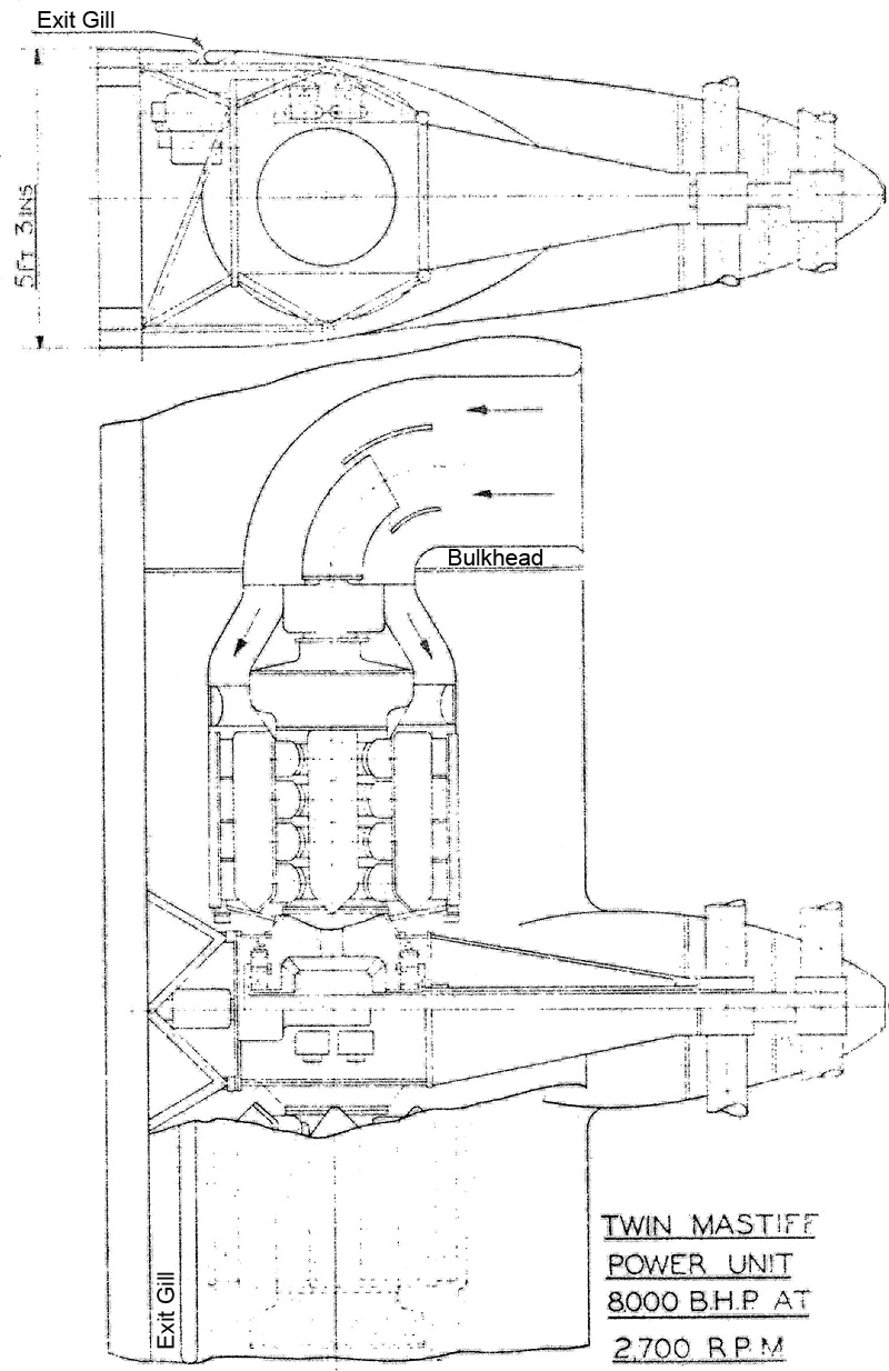
Arsenal was experienced with pairing engines in tandem to drive coaxial contra-rotating propellers, and they applied the concept to the 24H engine. Arsenal had developed a drive system for the Arsenal VB 10 fighter using a Vernisse or homocinetic coupling to join sections of the rear engine’s propeller shaft. This coupling incorporated flexibly-mounted ball joints to accommodate deflection and vibration of the propeller shaft. For the 24H Tandem engine, the propeller shaft of the rear engine passed through the crankcase, between the crankshafts, and extended through the propeller shaft of the front engine. The rear engine drove the front propeller of the coaxial contra-rotating unit, while the front engine drove the rear propeller. The Arsenal 24H Tandem displaced 8,541 cu in (139.96 L) and had a takeoff rating of 7,200 hp (5,369 kW), with some sources stating 8,000 hp (5,966 kW). The engine’s normal rating was 6,000 hp (4,474 kW) at 3,000 rpm. With a 39 in (1.0 m) shaft between the engine sections, the Tandem 24H weighed 9,039 lb (4,100 kg). Some sources claim that a 24H Tandem was constructed and run. The engine was considered for a few aircraft, including four 24H Tandem engines used in the Sud-Est 1200 flying boat. Cancellation of the 24H prevented any further development of the Tandem engine.

Arsenal 24H Tandem

The 8,000 hp (5,966 kw) Arsenal 24H Tandem held some potential in a world of large transport aircraft and no jet engines. Fortunately for aviation, the jet engine proved to be both viable and revolutionary.

Sources:
Les Moteurs a Pistons Aeronautiques Francais Tome 2 by Alfred Bodemer and Robert Laugier (1987)
Jane’s All the Worlds Aircraft 1949-1950 by Leonard Bridgman (1949)
Aircraft Engines of the World 1951 by Paul H. Wilkinson (1951)
Junkers Flugtriebwerke by Reinhard Müller (2006)
Les Avions de Combat Francais 1944-1960 I – Chasse-Assaut by Jean Cuny (1988)
Latécorère: Les avions et hydravions by Jean Cuny (1992)
World Encyclopedia of Aero Engines by Bill Gunston (2007)

Hispano-Suiza 24Z left

Hispano-Suiza 24Z (Type 95) Aircraft Engine

By William Pearce

Starting around 1938, Hispano-Suiza began to halt development of its other aircraft engines to focus on its latest V-12, the 12Z (Type 89). The 12Z drew heavily from the Hispano-Suiza 12Y but had many improvements, including two-speed supercharging and four-valves per cylinder actuated by dual-overhead camshafts. France was in desperate need of high-powered aircraft engines to keep its air force comparable to those of other European nations during the build-up to World War II. The 12Z was developing 1,400 hp (1,044 kW) at 2,600 rpm when France surrendered in June 1940.

Hispano-Suiza 24Z right

The Hispano-Suiza 24Z incorporated the improved features of the 12Z engine but was very similar to the 24Y. Note the high position of the propeller shafts to accommodate a cannon mounted between the upper cylinder banks and firing through the propeller hub. The magnetos for the right side of the engine can be seen mounted to the propeller gear reduction housing.

One of the engine programs that was suspended because of the 12Z was the Hispano-Suiza 24Y: a 2,200 hp (1,641 kW), 24-cylinder H engine utilizing many 12Y components. Not long into the 12Z program, engineers started to wonder what level of performance could be achieved by a 24-cylinder engine using 12Z components. In 1943 and under German occupation, development began on the Hispano-Suiza 24Z (Type 95) engine.

The 24Z had the same vertical H-24 configuration as the earlier 24Y with two cylinder banks situated above crankcase and another two cylinder banks below. The two-piece crankcase was made from aluminum and split horizontally. A crankshaft served each upper and lower cylinder bank pair. Each one-piece crankshaft had six-throws, was counterbalanced, and was supported by seven main bearings. The pistons were connected to the crankshafts via fork-and-blade connecting rods. The crankshafts, connecting rods, and pistons were the same as those used in the 12Z engine.

Each of the 24Z’s four cylinder banks was made up of a six-cylinder block with an integral crossflow cylinder head. The two intake valves and two exhaust valves for each cylinder were controlled by separate overhead camshafts. The camshafts were driven from a vertical shaft at the rear of each cylinder bank. The cylinder banks and their valve train were from the 12Z engine.

Hispano-Suiza 24Z left

Each left and right half of the 3,600 hp (2,685 kW) 24Z engine could operate independently of the other half. Note the intake manifolds routing air from the supercharger to the cylinder banks and the drive shaft for the fuel injection pump extending from the rear of the engine.

Two superchargers were mounted at the rear of the engine with their impellers parallel to the engine’s crankshafts. Originally, single-speed supercharges were used, but these were later replaced with two-speed units. At low speed, the supercharger’s impeller spun at 6.72 times crankshaft speed. At high speed, the impeller spun at 9.52 times crankshaft speed. Supercharger speed change and boost control were automatic. Separate intake manifolds led from each supercharger to the inner side of the upper and lower cylinder banks. Mounted on each side of the crankcase was a fuel pump that injected fuel directly into each cylinder. Each fuel pump was driven via a shaft from the rear of the engine. The two spark plugs per cylinder were positioned below the intake valves. The spark plugs for each upper and lower cylinder bank pair were fired by two magnetos mounted to the propeller gear reduction case.

The front of each crankshaft engaged a separate propeller shaft at a .44 to 1 gear reduction. The two propeller shafts made up a contra-rotating unit. The 24Z was not built with a single-rotation propeller shaft. The engine had provisions for a cannon to be mounted between the upper cylinder banks and fire through the hollow propeller shaft. Each upper and lower cylinder bank pair on the 24Z constituted a 12-cylinder engine section, and each engine section could operate independently of the other.

Sud-Est 580 HS 24Z

The Sud-Est SE 580 under construction with the 24Z engine installed. Note the supercharger intake on both sides of the cowling. Also note the upper and lower row of exhaust stacks. The scoop behind the cockpit was for the radiators.

The Hispano-Suiza 24Z had a 5.91 in (150 mm) bore and a 6.69 in (170 mm) stroke. The engine’s total displacement was 4,400 cu in (72.10 L). The 24Z produced 3,600 hp (2,685 kW) at 2,800 rpm for takeoff. This power was achieved at an over-boosted condition of 7.7 psi (.53 bar); normal boost was 7.0 psi (.49 bar). Max power with low-speed supercharging was 3,200 hp (2,386 kW) at 2,800 rpm at 8,202 ft (2,500 m). Max power with high-speed supercharging was 2,640 hp (1,969 kW) at 2,800 rpm at 26,247 ft (8,000 m). The engine’s normal rating was 3,000 hp (2,237 kW) at 2,600 rpm at 8,202 ft (2,500 m) with low-speed supercharging and 24,606 ft (7,500 m) with high-speed supercharging. The 24Z’s cruising power was 1,500 hp (1,119 kW) at 2,100 rpm at 9,843 ft (3,000 m) with low-speed supercharging and 18,373 ft (5,600 m) with high-speed supercharging. The engine had a specific fuel consumption of .48 lb/hp/hr (292 g/kW/hr). The 24Z was 10.72 ft (3.27 m) long, 4.27 ft (1.30 m) wide, 4.54 ft (1.39 m) tall, and weighed 3,197 lb (1,450 kg).

World War II hindered the 24Z’s construction. The engine was first run in 1946, and it was exhibited at the Salon de l’Aéronautique (Air Show) in Paris in November 1946. Bench tests of the 24Z revealed some serious issues, the extent of which have not been found. In September 1947, the engine’s compression was lowered to 6.75 to 1 from its original value of 7.0 to 1. Perhaps this change was an attempt to cure issues with detonation. Later, the gear reduction failed while a 24Z was under test, destroying the engine.

The 24Z’s prime application was the Sud-Est* SE 580/582 fighter that was designed during the war. However, issues with the 24Z resulted in the substitution of an Arsenal 24H engine for the SE 580. The SE 580 itself was later scrapped before the aircraft was completed. Many other projects, mostly flying boats and transports, were proposed with 24Zs as their power plant. None of these projects made it off the drawing board.

Hispano-Suiza 48Z Late 133

Drawing of two Hispano-Suiza 48Z engines installed in the wing of a Latécorère 133 flying boat. (image relabeled, but originally from “Latécorère: Les avions et hydravions” by Jean Cuny)

A further Hispano-Suiza proposal consisted of coupling two 24Z engines together to create the 48Z (Type 96) engine. In this configuration, the propeller shaft of the rear 24Z engine section passed between the upper cylinder banks of the front 24Z engine section and extend though the propeller shaft of the front engine. The rear 24Z powered the front propeller of a coaxial contra-rotating unit, while the front 24Z powered the rear propeller. The 48Z would have used four turbosuperchargers—two mounted near the front of the engine and two mounted at the rear. The 48-cylinder 48Z engine displaced 8,800 cu in (144.20 L), had a takeoff rating of 7,200 hp (5,369 kW) at 2,800 rpm, and produced 5,200 hp (3,878 kW) at 13,123 ft (4,000 m). Like many large engine projects at the dawn of the jet age, the 48Z existed only on paper.

With the 24Z’s developmental issues and no tangible prospects for installation in an aircraft, the engine program was stopped in 1948. At least two 24Z engines were built, but probably not many more. One engine survives and is preserved in the Musée de l’Air et de l’Espace in le Bourget (near Paris), France.

Hispano-Suiza 24Z

The Hispano-Suiza 24Z preserved in the Musée de l’Air et de l’Espace in le Bourget, France. Most likely, this is the engine that was displayed at the 1946 Salon de l’Aéronautique and was installed in the SE 580. (image via Le Rêve d’Icare)

*The SE 580/582’s development began at what was Dewoitine, which had been nationalized into SNCAM (Société nationale des constructions aéronautiques du Midi or National Society of Aircraft Constructors South). SNCAM was absorbed into SNCASE (Société nationale des constructions aéronautiques du Sud-Est or National Society of Aircraft Constructors Southeast), which is often shortened to just Sud-Est.

Sources:
Hispano Suiza in Aeronautics by Manuel Lage (2004)
Jane’s All the World’s Aircraft 1947 by Leonard Bridgman (1947)
Aircraft Engines of the World 1947 by Paul H. Wilkinson (1947)
Latécorère: Les avions et hydravions by Jean Cuny (1992)
– “Engines at the Paris Show” Flight (21 November 1946)

Hispano-Suiza 24Y Type 90 side

Hispano-Suiza 24Y (Type 82 and Type 90) Aircraft Engine

By William Pearce

In 1936, the Ministère de l’Air (French Air Ministry) issued a specification for a 2,000 hp (1,491 kW) engine intended to power a flying boat for transatlantic service. The aircraft was to carry at least 40 passengers and 1,100 lb (500 kg) of cargo 3,725 miles (6,000 km) against a 37 mph (60 km/h) headwind. Hispano-Suiza already had its 12Y engine of 1,000 hp (746 kW) in production and was investigating ways to effectively double that engine. Their design efforts led to the 24-cylinder Hispano-Suiza 24Y aircraft engine.

Hispano-Suiza 24Y Type 82 front 2

The Hispano-Suiza 24Y Type 82 24-cylinder H engine on display in the Polish Aviation Museum in Krakow. The Type 82 was intended for use with contra-rotating propellers; however, its original propeller shaft is missing.

The idea behind the 24Y engine was to utilize as many 12Y engine components as possible. The Hispano-Suiza 12Y engine was a liquid-cooled V-12. Each bank of six cylinders was cast en bloc with an integral cylinder head. The 12Y had a 5.91 in (150 mm) bore, a 6.69 in (170 mm) stroke, and a total displacement of 2,200 cu in (36.05 L). The 12Y-50 was one of the last and most powerful versions of the engine; it produced 1,100 hp (820 kW) at 2,500 rpm.

The 24Y engine’s configuration was a vertical H-24: two cylinder banks were mounted vertically above the crankcase, and two cylinder banks were below. A crankshaft served each upper and lower cylinder bank pair. Four aluminum 12Y-50* cylinder blocks were mounted on the 24Y’s crankcase. Each cylinder block included two valves per cylinder, a single overhead camshaft, and the camshaft’s vertical drive shaft. The 7 to 1 compression pistons were connected to the hollow, one-piece crankshaft via fork-and-blade connecting rods, and all components were from the 12Y engine. Each crankshaft had six throws and was supported by seven main bearings. The two-piece, aluminum crankcase was formed by an upper and lower half and was unique to the 24Y.

Hispano-Suiza 24Y Type 90 rear

Rear view of the Hispano-Suiza 24Y (Type 90) showing the engine’s four magnetos, two superchargers, four fuel pumps, and two coolant pumps.

At the rear of the engine, each crankshaft drove a single-speed supercharger at 10 times crankshaft speed. The superchargers gave the engine 2.3 psi (.16 bar) of boost. Separate intake manifolds led from each supercharger to the upper and lower cylinder banks on one side of the engine. Three carburetors were positioned along each intake manifold. Each of the engine’s 12 carburetors supplied the air/fuel mixture to a pair of cylinders.

The two spark plugs per cylinder were fired by four magnetos driven from the rear of the engine. Two magnetos were located above each supercharger. Four fuel pumps were mounted below and between the superchargers. The left and right sides of the engine had separate coolant systems, and a coolant pump was located below each supercharger.

At the front of the engine, each crankshaft had a 28-tooth gear that engaged a 55-tooth propeller gear. This combination created a .509 to 1 gear reduction for the propeller shaft. Between each crankshaft and its power gear was a Sarazin torsional vibration damper. Two versions of the 24Y were built, and they differed in their propeller drive. The 24Y Type 82 was designed to power contra-rotating propellers. In this engine, one crankshaft drove the inner propeller shaft while the other crankshaft drove the outer propeller shaft. The 24Y Type 90 was designed to power a single-rotation propeller and was available with either a normal length or extended gear reduction nose case. Some sources state the Type 90 had accommodations for a cannon to fire through the propeller shaft, but photos indicate this was unlikely.

Hispano-Suiza 24Y Type 90 side

Hispano-Suiza 24Y Type 90 engine with its extended gear reduction case for a single rotation propeller. This engine was displayed at the 1938 Salon de l’Aéronautique in Paris. Note the three carburetors for each cylinder bank.

The Hispano-Suiza 24Y had a 5.91 in (150 mm) bore and a 6.69 in (170 mm) stroke. The engine’s total displacement was 4,400 cu in (72.10 L). The 24Y produced 2,200 hp (1,641 kW) at 2,500 rpm for takeoff. Max power was 2,000 hp (1,491 kW) at 2,400 rpm at 10,827 ft (3,300 m), and cruising power was 1,500 hp (1,119 kW) at 2,250 rpm at 10,827 ft (3,300 m). The engine had a specific fuel consumption of .50 lb/hp/hr (304 g/kW/hr). The Type 82 was 6.46 ft (1.97 m) long, 3.05 ft (.93 m) wide, and 4.27 ft (1.30 m) tall. The engine weighed 2,204 lb (1,000 kg). The Type 90 had the same width and height as the Type 82 but was 3.38 ft (1.03 m) longer with the extended gear reduction case, for a total length of 9.84 ft (3.00 m). The Type 90’s weight was listed as 2,161 lb (980 kg).

Exactly when the 24Y was first run has been lost to history. The engine made its public debut in November 1938 at the Salon de l’Aéronautique (Air Show) in Paris, France. A Type 90 engine was displayed there, and it attracted a lot of attention. Unfortunately for Hispano-Suiza, that attention did not translate into sales. War in Europe was imminent by 1939, and Hispano-Suiza had turned its attention to developing the new 12Z engine. The 12Z was the next evolutionary step beyond the 12Y for Hispano-Suiza’s V-12 engines. War would interrupt the 12Z’s development, but the 12Z would later inspire another 24-cylinder engine known as the 24Z, which was configured like the 24Y. It is doubtful that the 24Y was ever flown.

Hispano-Suiza 24Y Type 82 side

The preserved 24Y Type 82 engine is missing many components. Note the vertical drive shaft for the camshaft at the end of each cylinder bank. (Polish Aviation Museum image)

Only a small number of 24Y engines were built—probably just one Type 82 and one Type 90 with an extended gear reduction case. Having disappeared during World War II, the disposition of the Type 90 is not known. The Type 82 wound up in Poland at the end of World War II. Most likely, it was part of Herman Goering’s aviation collection that was moved to Poland late in the war to keep it from being damaged during Allied bombing raids. The Hispano-Suiza 24Y Type 82 engine is currently preserved (without its original propeller shaft) and on display in the Polish Aviation Museum in Krakow.

*Some sources state that 12Y-51 cylinder blocks were used on the 24Y. The 12Y-50 and 12Y-51 were basically the same engine, the only difference being the crankshaft rotation. When viewed from the rear, the 12Y-50 rotated counter clockwise; the 12Y-51 rotated clockwise. The cylinder blocks of the 12Y-50 and 12Y-51 engines were the same.

Hispano-Suiza 24Y Type 82 rear

The supercharger impellers can be seen in this view of the 24Y Type 82. Although the magnetos are gone, the fuel pumps and one coolant pump remain. (Polish Aviation Museum image)

Sources:
Aircraft Engines of the World 1941 by Paul H. Wilkinson (1941)
Hispano Suiza in Aeronautics by Manuel Lage (2004)
Jane’s All the World’s Aircraft 1939 by C. G. Grey and Leonard Bridgman (1939)
– “Some Trends in Engine Design” Flight (8 December 1938)
http://www.muzeumlotnictwa.pl/zbiory_sz.php?ido=121&w=a

Armstrong Siddeley Deerhound III

Armstrong Siddeley ‘Dog’ Aircraft Engines

By William Pearce

The British firm Armstrong Siddeley Motors (ASM) was formed in 1919 when Armstrong Whitworth (founded in 1847) purchased Siddeley-Deasy (founded in 1912). Prior to the merger, both Armstrong and Siddeley were active in the automotive and aeronautical fields. Siddeley first began manufacturing aircraft engines in 1915 under a contract to build the Royal Aircraft Factory’s RAF 1A engine. In 1916, Siddeley had built its first aircraft engine—the Puma—which was developed from the B.H.P. (Beardmore-Halford-Pullinger) six-cylinder engine. The Puma was the first in a long line of engines that were produced by ASM into the 1940s and named after cats (felines)—the last being the Cougar of 1945.

Armstrong Siddeley Hyena AW16

Two versions of the cowling used to cover the 15-cylinder Armstrong Siddeley Hyena installed in an Armstrong Whitworth A.W.XVI (A.W.16). The cowling on the right is illustrative of the Hyena’s inline radial cylinder arrangement.

In 1932, ASM worked to develop a new line of air-cooled, radial engines. These engines would be a design departure from their existing cat-engines, so they decided to name the engines after dogs (canines). Unfortunately, none of these engines were successful, and information about them is frustratingly hard to find and occasionally contradictory. To add to the confusion, some of the engine names were used more than once, and the engines possess many of the same characteristics.

The first engine of the new dog-series was the Mastiff (this name was used again later). This engine was built in 1932 and was a large radial engine with two rows of seven cylinders. The specifications of the 14-cylinder engine are currently not known. In reviewing a photo (that is unfortunately not publishable) of the Mastiff, the engine closely resembles a larger version of the 1,996 cu in (32.7 L) ASM Tiger in appearance and construction. The Mastiff was supercharged and had a one-piece crankcase and gear reduction. A cam ring at the front of the engine acted on pushrods that actuated each cylinder’s two valves. One Mastiff was built for Italy, but it is not known if the engine was ever tested.

Armstrong Siddeley Deerhound I side

This photo gives a good view of the 21-cylinder Armstrong Siddeley Deerhound I’s configuration. Note the engine’s inline radial layout and the vertical shaft in front of each cylinder bank to drive the overhead camshaft.

The second dog-engine was the Hyena. The Hyena’s 15 air-cooled cylinders were arranged in three rows of five. Even more unusual than the three-row arrangement was the fact that the cylinder rows were inline rather than staggered. Between each of the engine’s five cylinder banks was a camshaft that acted upon short pushrods to actuate the two valves per cylinder. The camshafts were geared to the crankshaft.

The Hyena had a 5.39 in (137 mm) bore and a 4.92 (125 mm) stroke. The engine’s total displacement was 1,687 cu in (27.64 L), and it produced 620 hp (462 kW) at 2,250 rpm. The Hyena was first run in 1933 and was installed in an Armstrong Whitworth A.W.XVI (A.W.16) biplane fighter later that year. The Hyena-powered A.W.XVI (registered as G-ABKF) first flew on 25 October 1933. The basic engine proved itself to be mechanically sound but rather heavy for its power. Issues were encountered with cooling the rear cylinders. This led to a number of different engine cowlings being tried, but the overheating issues persisted. Eventually, further development of the Hyena was abandoned, and only one or two engines were built. The Hyena was proposed to power the A.W.21 and A.W.28 fighters, but these projects did not proceed past the design stage.

Armstrong Siddeley Deerhound I rear

This rear view of the Deerhound I shows the supercharger housing with intake manifolds leading to each bank of cylinders.

Lessons learned from the Hyena were applied to the next dog-engine: the Deerhound. Led by Lt. Col. F. L. R. Fell, the design of the Deerhound was underway by late 1935, and it retained the inline radial cylinder configuration of the Hyena. However, the Deerhound had two addition cylinders for each row, making three rows of seven cylinders. Each cylinder bank of the Deerhound used a single overhead camshaft to actuate each cylinder’s two valves. The camshafts were driven from the crankshaft by a vertical shaft at the front of the engine. The Deerhound had a single-stage, two-speed supercharger and a propeller reduction gear of .432.

The 21-cylinder Deerhound had a 5.31 in (135 mm) bore and a 5.00 in (127 mm) stroke. The engine displaced 2,330 cu in (38.18 L) and had a forecasted output of 1,500 hp (1,119 kW). The Deerhound was seen as insurance against the potential failure of the Bristol Hercules engine then under development. The designers of the Deerhound would have preferred to create a liquid-cooled engine in the 1,500 hp (1,119 kW) class, but ASM management (John Siddeley) insisted on air-cooling. One of the engine’s designers, W. H. “Pat” Lindsey, stated the engine was “old-fashioned” and did not possess many then-modern refinements.

Armstrong Siddeley Deerhound construction

This photo shows five Deerhound engines in various stages of assembly. Most likely, all of the engines are Deerhound Is, but it is possible one is a Deerhound II. From left to right, the engines appear to be numbered D1, D5, D3, D4, and D2. The engine marked D5 is definitely a Deerhound I.

The Deerhound was first run in 1936, and it was not long before cooling and other problems were encountered. Most likely, five engines were built, and the last achieved 1,370 hp before it failed. In 1937, the ASM board tasked Fell to redesign the engine to cure its ills. The redesign resulted in the Deerhound II, which will be described later. The Deerhound was proposed for the Armstrong Whitworth A.W.42 heavy bomber.

Another engine from 1935 was the Terrier. The Terrier was a two-row radial engine in which each row had seven cylinders. Again, specifics of the engine’s configuration are not available, but most likely the Terrier was effectively a two-row, 14-cylinder Deerhound. Retaining the Deerhound’s 5.31 in (135 mm) bore and a 5.00 in (127 mm) stroke, the engine would have a displacement of 1,553 cu in (24.45 L). The Terrier had a 6.6 to 1 compression ratio.

Armstrong Siddeley Deerhound II side

An Armstrong Siddeley Deerhound II partially assembled. The front of the engine, gear case, and valve covers have all be redesigned from that used on the Deerhound I. Note the overhead camshaft and valve arrangement visible on the upper cylinder bank.

Like the Deerhound, the Terrier had a single-stage, two-speed supercharger. The engine produced a maximum of 550 hp (410 kW) at 2,700 rpm for takeoff, 510 hp (380 kW) at 2,100 rpm at 6,500 ft (1,981 m), and 476 hp (355 kW) at 3,100 rpm at 14,700 ft (4,481 m). Normal outputs were 470 hp (350 kW) at 2,700 rpm at 5,000 ft (1,524 m), and 450 hp (336 kW) at 2,700 rpm at 12,000 ft (3,658 m). The Terrier was proposed for a number of projects including the Armstrong Whitworth F.9/35 turret fighter proposal, the Blackburn M.15/35 torpedo bomber proposal, and the Avro 672 and 675 multi-role aircraft designs. None of those projects were built, and work on the Deerhound prevented the Terrier from being constructed.

Also in 1935, the Whippet was designed. Specifics of the Whippet are not available, but the 250 hp (186 kW) engine may have had two rows of seven cylinders with a bore and stroke of around 4.02 in (102 mm). That cylinder size would give the engine a total displacement of around 712 cu in (11.67 L). The Whippet did not proceed beyond the design phase.

The next engine design was initiated around 1936 and was for the Wolfhound (this name was used again later). The inline radial Wolfhound was an outgrowth of the Deerhound and had four rows of seven cylinders. Specifics of the engine are not available. However, 28 cylinders with the Deerhound’s 5.31 in (135 mm) bore and 5.00 in (127 mm) stroke would displace 3,106 cu in (50.90 L) and produce around 1,800 hp (1,342 kW). The Wolfhound did not make it off the drawing board.

Deerhound II engine Whitley

A Deerhound II engine installed in an Armstrong Whitworth A.W.38 Whitley bomber. Note the relatively small diameter of the engine compared to that of the firewall. The 44 in (1.12 m) diameter Deerhound replaced the 51 in (1.29m) diameter Armstrong Siddeley Tiger that was originally installed in the Whitley II.

In 1937, the Deerhound was redesigned and became the Deerhound II. The engine’s configuration changed little. However, refinements were made, and the cylinder bore was increased from 5.31 in (135 mm) to 5.51 in (140 mm). The stroke was unchanged, but the larger bore increased the engine’s displacement by 175 cu in (2.88 L), bringing the total displacement to 2,505 cu in (41.06 L). The engine’s forecasted output was still 1,500 hp (1,119 kW). The Deerhound II had a 6.75 to 1 compression ratio and was 44 in (1.12 m) in diameter. Extensive baffles were installed around the cylinders to help direct air flow and cool the rear cylinders.

The Deerhound II was first run in 1938, but more issues were encountered, including a broken crankshaft during a type test in October 1938. Fell and his team were under immense pressure from the ASM board to fix the engine’s issues. Two Deerhound II engines were installed in an Armstrong Whitworth A.W.38 Whitley bomber (serial no. K7243) for flight tests, and the aircraft first flew in January 1940. Fell’s contract with ASM was not renewed when it expired on 9 February 1939. Lindsey temporarily took over Deerhound development until Stewart S. Tresilian was brought on staff in mid-1939.

Deerhound engine cowling Whitley

Any aerodynamic advantages achieved by the close-fitting cowling covering the Deerhound engine installed on the Whitley must have been undermined by the bulbous cooling-air intake under and the large induction scoop above the engine. This Whitley was eventually lost, but through no fault of the engines.

Although the date is not recorded, the engine did achieved and output of 1,500 hp (1,119 kW) at 2,975 rpm with 5 psi (.34 bar) of boost. On the Whitley bomber, the engines were housed in special nacelles. Cooling air was taken in under the spinner and directed from the rear of the engine forward through the cylinders. However, engine cooling issues persisted, and the designers believed increasing the cooling fin area of the cylinders would resolve the problem.

Flight testing continued until 6 March 1940 when the Deerhound II-powered Whitley bomber was lost on takeoff, killing all three people on board. The crash was attributed to an improperly set trim tab and had nothing to do with the engines. With the testbed destroyed, ASM decided to curtain development of the Deerhound II and focus on an improved version that would cure the overheating issues. The new engine, the Deerhound III, will be described later. Five Deerhound II engines were built.

Armstrong Siddeley 36-cyl Mastiff

This drawing illustrates a coupled arrangement for two 36-cylinder Armstrong Siddeley Mastiff engines. The engine’s nine banks of four cylinders can be deduced from the drawing. A similar arrangement was purposed with two Deerhound engines.

In 1937, the Boarhound was designed. This engine possessed the larger 5.51 in (140 mm) bore of the Deerhound II and had a longer 6.30 in (160 mm) stroke. The real design change was the engine’s layout—the Boarhound had three inline rows of nine cylinders. With its 27 cylinders, the Boarhound displaced 4,058 cu in (66.50 L). Its initial and rather conservative estimated output was 2,300 hp (1,715 kW) at 2,700 rpm. The Boarhound had a diameter of 51 in (1.30 m). With all resources focused on the Deerhound, the Boarhound was never built.

Around 1938, the Mastiff name was resurrected and given to a further development of the Boarhound. The new Mastiff had four inline rows of nine cylinders. While the cylinder’s bore was still 5.51 in (140 mm), the stroke was lengthened to 6.69 in (170 mm). The 36 cylinders of the Mastiff engine displaced an impressive 5,749 cu in (94.21 L), and output was estimated at 4,000 hp (2,983 kW). Like the Boarhound, the Mastiff was not developed.

In 1940, Tresilian went to work on the Deerhound III to create an engine free from the issues experienced with the original Deerhound and the Deerhound II. The Deerhound III possessed the same bore, stroke, displacement, and 44 in (1.12 m) diameter as the Deerhound II. However, the engine was essentially redesigned, and its output was increased to 1,800 hp (1,342 kW). The engine was first run in late 1940. High-power tests revealed detonation issues with the first row of cylinders, but some sources state the engine did achieve 1,800 hp (1,342 kW) on the dyno. An updated design, the Deerhound IV, was proposed but never built. Only one Deerhound III was built.

Armstrong Siddeley Deerhound III

This picture shows the sole Armstrong Siddeley Deerhound III engine. Again, revisions to the front of the engine, gear reduction, and valve covers can easily be seen. Reportedly, this engine survived into the 1970s.

In mid-1941, the Wolfhound name was reused for a new Tresilian-designed engine. The new Wolfhound had four inline rows of six cylinders in a flattened X configuration. The 24-cylinder engine had a 5.91 in (150 mm) bore and a 5.51 in (140 mm) stroke. Total displacement was 3,623 cu in (59.38 L), and the engine was to produce 2,600–2,800 hp (1,939–2,088 kW) at 2,800 rpm. The engine had a two-stage supercharger and was designed to power contra-rotating propellers.

In October 1940, a bombing raid severely damaged the Armstrong Siddeley Aero Development shop and destroyed several Deerhound engines. Another raid on 8 April 1941 further damaged the shop and set engine development back even more. ASM dog-engine development continued at a slow pace until October 1941, when the British Ministry of Aircraft Production (MAP) cancelled further work. The ASM dog-engines would not be ready in time to be of any use in the war, and the MAP wanted the company to focus on turbine engines (ASM named theirs after snakes). The sole Deerhound III engine was thought to have survived into the 1970s, but there are no known ASM dog-engines currently preserved.

Armstrong Siddeley Deerhound IV

Drawing of the Armstrong Siddeley Deerhound IV engine that was never built. Even if this design from 1941 proved successful, it would not have been developed in time to see much use during World War II.

Sources:
Armstrong Siddeley — the Parkside Story 1896–1939 by Ray Cook (1988)
Parkside: Armstrong Siddeley to Rolls-Royce 1939–1994 by Roy Lawton (2008)**
Sectioned Drawings of Piston Aero Engines by Lyndon Jones (1995)**
Armstrong Whitworth Aircraft since 1913 by Oliver Tapper (1973)
British Secret Projects: Fighters & Bombers 1935–1950 by Tony Buttler (2004)
British Piston Aero-Engines and Their Aircraft by Alec Lumsden (1994/2003)
http://www.designchambers.com/wolfhound/index.htm#Articles (and pages therein)
http://www.secretprojects.co.uk/forum/index.php?topic=5580.0

**Rolls-Royce Heritage Trust books that are currently in print and available from the Rolls-Royce Heritage Trust site.

Junkers-Jumo-224-side

Junkers Jumo 224 Aircraft Engine

By William Pearce

Under Junkers engineer Manfred Gerlach, development of the Junkers Motorenbau (Jumo) 224 two-stroke, opposed-piston, diesel aircraft engine began when the development of the Jumo 223 stopped in mid-1942. The Jumo 223 had encountered vibration issues as a result of its construction, and its maximum output of 2,500 hp (1,860 kW) fell short of what was then desired. More power was needed for the large, long-range aircraft on the drawing board.

Junkers Jumo 224

Front and side sectional views of the Junkers Jumo 224 engine. Note in the side view how the turbochargers feed the supercharger/blower mounted in the “square” of the engine. The front of the crankshafts engage gears for the propellers, supercharger, and fuel injection camshafts.

The Jumo 224 retained the same basic configuration as the Jumo 223, with four six-cylinder banks positioned 90 degrees to each other so that they formed a rhombus—a square balanced on one corner (◇). The pistons for two adjacent cylinder banks were attached to a crankshaft located at each corner of the rhombus. The complete engine had four crankshafts, 24 cylinders, and 48 pistons.

Like the Jumo 223, the Jumo 224 engine was constructed from two large and complex castings—one for the front of the engine and one for the rear. Each casting had four banks of three-cylinders. To enable the use of contra-rotating propellers, two gears were connected to the front of each crankshaft. The first gear was the bigger of the two and engaged a large central gear at the front and center of the engine. The outer propeller shaft was connected to the front of the central gear. Through an idler gear, the small gears on all the crankshafts drove a smaller central gear that was connected to the inner propeller shaft. However, the engine could be configured for use with a single propeller rotating in either direction. The central gears provided an engine speed reduction of .35.

Junkers Jumo 223 with prop

Although never completed, the  Jumo 224 would have closely resembled a larger version of the Jumo 223 shown above.

The upper and lower crankshafts also drove separate camshafts for the left and right rows of fuel injection pumps. These camshafts as well as the injection pumps were located near the upper and lower crankshafts. Through a series of step-up gears, the left and right crankshafts powered a drive shaft for the engine’s supercharger/blower, which was located in the rear “square” of the engine.

Exhaust gases from each cylinder bank were collected by a manifold that led to a turbocharger at the rear of the engine. Each of the four cylinder banks had its own turbocharger. After passing through the turbocharger, the air flowed into the supercharger where it was further pressurized, and then into the cylinders via a series of holes around the cylinder’s circumference. As the pistons moved toward each other, the intake holes were covered and the air was compressed. Diesel fuel was injected and ignited by the heat of compression. The expanding gases forced the pistons away from each other, uncovering the intake holes (for scavenging) and then the exhaust ports, which were located near the left and right crankshafts.

At its core, the Jumo 224 was four Jumo 207C inline, six-cylinder, opposed-piston engines combined in a compact package. Using the proven Jumo 207C as a starting point cut down the development time of the Jumo 224 engine. The Jumo 224 used the same bore and stroke as the Jumo 207C. While the Jumo 224 was being designed, a Jumo 207C was tested to its limits to better understand exactly what output could be expected from the Jumo 224. Tests conducted in late 1944 found that with a 200 rpm overspeed (3,200 rpm), intercooling, modified fuel injectors, and 80% methanol-water injection, the Jumo 207C was capable of a 10 minute output at 2,210 hp (1,645 kW)—twice its standard rating of 1,100 hp (820 kW).

Junkers Jumo 207C

The Junkers Jumo 207C had an integral blower and turbocharger. The engine served as the foundation for the Jumo 224; its cylinder dimensions and various components were used.

The Jumo 224 had a bore of 4.13 in (105 mm) and a stroke of 6.30 in (160 mm) x 2 (for the two pistons per cylinder). Total displacement was 4,058 cu in (66.50 L). Without turbochargers, the engine was 111.4 in (2.83 m) long, 66.9 in (1.70 m) wide, 73.6 in (1.87 m) tall, and weighed 5,732 lb (2,600 kg). The opposed pistons created a compression ratio of 17 to 1. The planned output of the Jumo 224 was initially 4,400 hp (3,280 kW) at 3,000 rpm. However, many different combinations of intercooling, multiple-stage turbocharging, turbocompounding, and using exhaust thrust for up to 400 hp (300 kW) of extra power were proposed that gave the engine a variety of different outputs at critical altitudes up to 49,210 ft (15,000 m). Specific fuel consumption was estimated as .380 lb/hp/hr (231 g/kW/hr), and the engine’s average piston speed was 3,150 fpm (16.0 m/s) at 3,000 rpm.

From mid-1942 on, design work on the complex Jumo 224 moved ahead but often at a very slow pace. Developmental work on the 24-cylinder Jumo 222 and turbojet Jumo 004 engines took up all of the engineers’ time and Junkers Company resources, leaving little of either for the Jumo 224. The RLM (Reichsluftfahrtministerium or German Ministry of Aviation) was interested in the Jumo 224 engine for the six-engine Blohm & Voss BV 238 long-range flying boat, the eight-engine Dornier Do 214 long-range flying boat, and other post-war commercial and military aircraft projects. Even so, the RLM was more interested in the other Jumo engines, and they were given priority over the Jumo 224.

junkers-jumo-224-gears

Gearing schematic of the Jumo 224 showing left and right propeller rotation. The drawing indicates the number of teeth (z) and their height (m) on each gear.

By October 1944, the Jumo 207D engine had proven itself reliable. This engine had a bore of 4.33 in (110mm)—.20 in (5 mm) more than the Jumo 207C. Thought was given to using Jumo 207D cylinders for the Jumo 224. This change would have increased the engine’s displacement by 396 cu in (6.5 L), resulting in a total displacement of 4,454 cu in (73.0 L). However, it is not clear if the larger bore was ever incorporated into the Jumo 224.

In November 1944 the RLM ordered the material for five Jumo 224 engines. At this stage in the war, with streams of Allied bombers overhead, it was nearly impossible for Junkers to find contractors able to produce the specialized components needed for the Jumo 224 engine. Even under ideal conditions, it would be years before the Jumo 224 engine would be ready for production. By the end of the war, the first Jumo 224 engine was around 70% complete. As Allied troops neared the Junkers factory in Dessau, Germany in late April 1945, almost all of the Jumo 224 plans, blueprints, and documents were destroyed to prevent the information from falling into the hands of the Allies.

After the Junkers plant was captured, the Jumo 207C that produced 2,210 hp was sent to the United States for study. The plant, Dessau, and all of eastern Germany was handed over to the Soviet Union. In March 1946, the Soviets expressed interest in the Jumo 224 (and 223) engine, and development continued in May 1946. Gerlach was still at the Junkers plant and continued to oversee the Jumo 224. However, building the engine in post-war, Soviet-occupied Germany proved to be more of a challenge than building the engine during the war. Jumo 224 development continued but at a very slow pace. In October 1946, Gerlach and a number of others were relocated to Tushino (now part of Moscow), Russia to continue work on the Jumo 224.

Junkers Jumo 224 installation

Installation drawing for the Jumo 224. Clearly seen are the four turbochargers and contra-rotating propellers. The inside cowling diameter is listed as 72.8 in (1.85 m).

Operating out of State Factory No. 500, the group was to continue development of the Jumo 224 engine, now designated M-224. The M-224 was turbocharged, 123.1 in (3.13 m) long, 66.9 in (1.70 m) wide, 74.7 in (1.90 m) tall, and weighed 6,063 lb (2,750 kg). Gerlach believed in the M-224 and did what he could to continue its development, but the Germans did not find themselves very welcome at the factory, and nearly everything they requested was slow in coming. To make matters worse, Jumo 224 parts and equipment that the Soviets had captured and sent from Dessau never arrived in Tushino.

Junkers Jumo 224 advert

Junkers post-World War II advertisement for the Jumo 224 stating the high performance diesel aircraft engine was for large, long-distance aircraft.

Factory No. 500 was headed by Vladimir M. Yakovlev (no relation to the aircraft designer), who was hard at work on his own large diesel aircraft engine—the 6,200 hp (4,620 kW), 8,760 cu in (143.6 L), 42-cylinder M-501. Yakovlev was critical of the work done on the M-224; he felt that the engine took resources away from the M-501. With little progress on the M-224, Yakovlev was able to convince Soviet officials that his engine had the greater potential, and all development on the M-224 was stopped in mid-1948.

No parts or mockups of the Jumo 224 / M-224 are known to exist. The Yakovlev M-501 engine was run in 1952. The engine was not produced for aircraft, but it was built in the 1970s as the Zvezda M503 marine engine and is still used today for tractor pulling.

Sources:
Junkers Flugtriebwerke by Reinhard Müller (2006)
Flugmotoren und Strahltriebwerke by Kyrill von Gersdorff, et. al. (2007)
Russian Piston Aero Engines by Vladimir Kotelnikov (2005)
Opposed Piston Engines by Jean-Pierre Pirault and Martin Flint (2010)
https://ru.wikipedia.org/wiki/%D0%9C-224

Junkers Jumo 223 front

Junkers Jumo 223 Aircraft Engine

By William Pearce

In 1892, Hugo Junkers began experimental development of two-stroke, opposed-piston, gas engines. By 1910, Junkers had combined the opposed-piston principal with the diesel combustion cycle (compression ignition). Junkers investigated adapting this style of engine for aircraft use, but World War I and its aftermath prolonged development. In 1923, Junkers formed the Junkers Motorenbau (Jumo) to construct aircraft engines. Jumo’s first two-stroke, opposed-piston, diesel aircraft engine was commercially available in 1930. Originally known as the Jumo 4, the engine’s designation was changed in 1932 to Jumo 204.

Junkers Jumo 223 front

The 24-cylinder Junkers Jumo 223 two-stroke, opposed-piston, diesel aircraft engine was one of the most unusual engines ever built. The engine’s coolant exit ports can be seen by the upper crankshaft. The two starters at the front of the engine engaged the propeller shaft.

Throughout the 1930s, Junkers developed a number of two-stroke, opposed-piston, diesel aircraft engines. There is no cylinder head on an opposed-piston engine. Rather, each cylinder has two pistons that move toward the center of the cylinder during the compression stroke. Ports in the cylinder wall allow the admission of air and expulsion of exhaust. These ports are covered and uncovered by the pistons as they move. The Junkers opposed-piston diesels were six-cylinder, inline engines with two crankshafts—one at the top of the engine and one at the bottom. Each crankshaft had a complete set of six pistons.

For installation in aircraft, there were practical limits to the Junker’s inline, opposed-piston engine configuration. Its double piston design made it a very tall engine, adding more cylinders to the Junkers diesels would have created a very long engine with a long crankshaft susceptible to torsional stresses. Increasing the engine’s bore and/or stroke would result in a larger engine with a lot of rotating mass, necessitating relatively low rpm. Engines capable of a continuous 2,000 hp (1,490 kW) output were needed for proposed large transoceanic aircraft, but an inline, opposed-piston aircraft engine able to produce 2,000 hp (1,490 kW) of continuous power was simply not feasible.

Junkers Jumo 204

The Jumo 204 was the first diesel aircraft engine commercially available from Junkers. Its basic configuration was repeated in later Jumo diesels—collectively the most successful diesel aircraft engines produced.

By 1936, Junkers engineer Dr. Johannes Gasterstädt had come up with an opposed-piston engine configuration that would enable 2,000 hp (1,490 kW) in a compact package suitable for aircraft use. The configuration consisted of four cylinder banks positioned 90 degrees to each other so that they formed a rhombus—a square balanced on one point (◇). The pistons for two adjacent cylinder banks were connected to a crankshaft positioned at each corner of the rhombus. Each cylinder bank had six cylinders. The complete engine had four crankshafts, 24 cylinders, and 48 pistons.

Junkers’ rhombus-configured engine investigation was designated P2000. Dr. Gasterstädt passed away in 1937, and Prof. Otto Mader and Manfred Gerlach took over the P2000 project. By the end of 1937, a single cylinder test engine and a complete six-cylinder block had been built and run. In April 1938, the RLM (Reichsluftfahrtministerium or German Ministry of Aviation) redesignated the P2000 engine as the Jumo 223. By December 1939, a full-scale Jumo 223 engine was completed, and that engine was run-in by a dyno (the dyno turning the engine) in January 1940.

Junkers Jumo 223 split case

This picture of the separate castings that made up the Jumo 223 helps to illustrate the engine’s complexity. Note the scuffing and carbon deposits on the pistons, indicating they have been run.

The Jumo 223 was one of the most unusual engines ever built. The engine was constructed from two large and complex aluminum castings—one for the front of the engine and one for the rear. Each casting had four banks of three-cylinders. A large central gear was at the center of the engine where the two castings joined. Each crankshaft was made up of two main sections bolted together via a gear at its center. The gear on each crankshaft meshed with the central gear to transfer power from the crankshafts to the central gear. Drive shafts extended through the center of the engine from the front and rear of the central gear. The rear shaft powered the engine’s blower (weak supercharger) and accessories via a series of other gears. The front shaft led to the propeller. The central gear provided a .26 reduction in engine speed. At the front of the engine were two starters that engaged the propeller shaft to start the engine.

Junkers Jumo 223 cranks gear

The Jumo 223’s central gear was powered by gears at the center of the engine’s four crankshafts. Note the fork-and-blade connecting rods.

The left and right crankshaft gears each drove separate camshafts for an upper and lower row of fuel injection pumps. These camshafts and the injection pumps were located near the left and right crankshafts. Cast directly under each row of injection pumps was a square port that ran along the engine. This port took air from the blower and delivered it to a small chamber around each steel cylinder liner. Air entered the cylinders via a series of holes around the cylinder liner’s circumference. The fuel injectors were located in the center of the cylinder. As the pistons moved toward each other, the intake holes were covered and the air was compressed. Diesel fuel was injected and ignited by the heat of compression. The expanding gases forced the pistons away from each other, uncovering the intake holes (for scavenging) and then the exhaust ports, which were located near the upper and lower crankshafts. Exhaust gases flowed out the ports in the cylinder liner into a small chamber surrounding the liner. The exhaust gases for each cylinder bank were collected by a manifold that led to a turbocharger at the rear of the engine. It is not clear if the turbocharger was ever tested, but there is one photo that shows a Jumo 223 with the turbocharger or a mockup of it. The pistons were connected to the crankshaft via fork-and-blade connecting rods. Each crankshaft was secured in the crankcase by eight main bearings.

A triangular port for coolant was cast on both sides of the engine near the upper and lower crankshafts. Coolant flowed from the coolant pump located on the bottom rear of the engine and into the lower triangular ports. The coolant circulated throughout the engine and exited near the upper crankshaft via the coolant ports at the front of the engine.

Junkers Jumo 223 central gear

The central gear and front half of the engine is shown in this picture. Note the gears for the fuel injection pump camshafts by the left and right crankshafts. Coolant flowed through the triangular ports near the upper and lower crankshafts. Air flowed through the square ports near the left and right crankshafts.

The Jumo 223 engine had a 3.15 in (80 mm) bore and a 4.72 in (120 mm) stroke x 2 (for the two pistons per cylinder). Total displacement was 1,767 cu in (28.95 L). Without the propeller, the engine was 81.5 in (2.07 m) long, 48.8 in (1.24 m) wide, 53.0 in (1.345 m) tall, and weighed 3,086 lb (1,400 kg). The opposed pistons created a compression ratio of 17 to 1. With its planned intercooled turbocharger, the Jumo 223 was designed to produce 2,500 hp (1,860 kW) at an astonishing 4,400 rpm. That rpm would yield a fairly high average piston speed of 3,465 fpm (17.6 m/s). The Jumo 223 had a critical altitude rating of 1,800 hp (1,340 kW) at 16,404 ft (5,000 m) with the possibility of increasing the altitude to 32,808 ft (10,000 m) as the engine was further developed. Specific fuel consumption was .391 lb/hp/hr (238 g/kW/hr). The engine was contemplated for use in the four-engine Messerschmitt Me 264 long-range bomber, the six-engine Junkers EF100 commercial airliner, and other military aircraft projects.

The Jumo 223 engine ran for the first time on 27 February 1940. Without the turbocharger, the only boost came from the engine’s blower that was just intended to scavenge the cylinders. Peak high temperatures of 2,552 degrees F (1,400 degrees C) were encountered in the cylinders during combustion and caused pitting and seizure of the pistons. The issue was caused by the asymmetrical injection of fuel, a result of locating the injectors only on the outside of the engine, for ease of service, rather than having additional injectors inside the engine’s “square.”

Junkers Jumo 223 rear

The blower at the rear of the Jumo 223 can clearly be seen in this picture. The pipes leading away from the blower provided air to the passageways cast in the engine. The coolant pump is at the bottom of the engine.

Fuel injectors were modified, and tests continued throughout 1940. Three engines had been built by early 1941. In February 1941, the second engine was run for 100 hours and achieved a peak of 1,830 hp (1,360 kW) at 3,810 rpm. On 20 March 1941, the Jumo 223 passed the 2,000 hp (1,490 kW) mark by producing 2,040 hp (1,520 kW) at 3,980 rpm. During a 100 hour engine run in July 1941, crankshaft bolts and crankshafts were broken, indicating resonance vibration issues. In October 1941, the third engine completed a 100 hour test run at 1,500 hp (1,115 kW). The engine was run at a lower power because of the issues encountered when the Jumo 223 engine produced more power. The second engine was back in the test cell for a short run on 23 December 1941. The run set the mark for the highest power achieved by the Jumo 223 engine, producing 2,380 hp (1,770 kW) at 4,200 rpm.

Tests continued into 1942, but the engine’s reliability was a concern. The vibration issues seemed to be a result of the two-piece crankshafts and crankcase and the high rpm needed to produce the desired power. Along with the Jumo 223, Junkers was developing the Jumo 222—a 24-cylinder, spark ignition engine close to the same power and physical size as the Jumo 223, but lighter and of greater displacement. The Jumo 222 engine had more than its share of problems, and it made little sense to develop two engines in the same power class at the same time. In addition, developmental engines capable of more power than the Jumo 223 were needed.

Junkers Jumo 223 with turbo

This photo shows a Jumo 223 with a turbocharger. The exhaust manifolds can be seen leading to the turbocharger at the rear of the engine. Unfortunately, no information has been found regarding tests of this engine. It is possible that the turbocharger was only a mockup.

Development of the Jumo 223 as a production engine was halted in mid-1942. However, work on the engine continued, as it would serve as a model for a new, larger engine—the Jumo 224. By October 1942, six Jumo 223 engines were completed and two more were under construction. The eighth and last Jumo 223 prototype engine was run up to 2,200 hp (1,640 kW) on 28 February 1943. While this run was intended to be the last, Soviet forces had different ideas after the war. The Junkers factory was in Dessau, Germany and was part of the territory occupied by Soviet troops. The Soviets were interested in the Jumo 223 engine. The eighth example was run again on 23 March 1946 and for the last time on 4 April 1946. The last run was for a Soviet delegation and lasted 73 minutes. The run was halted after two pistons failed. Reportedly, at least one of the Junkers Jumo 223 engines was taken to State Factory No.500 in Tushino (now part of Moscow), Russia for further research, but no Jumo 223 engines are known to exist.

Note: There is no doubt that the Junkers Jumo opposed-piston engines in some way inspired the Napier Deltic, especially since Napier purchased licenses to build the Jumo 204 and 205 engines (to be built as the Culverin and Cutlass) in the 1930s. However, there is no indication that information on the Jumo 223 or 224 engines was applied to the design of the Deltic. In fact, the Deltic possessed many unique design characteristics, such as one crankshaft rotating the opposite direction compared to the other two.

Junkers Jumo 223 test run

The first Jumo 223 engine running on a test stand at the Junkers works in Dessau, Germany in early 1940.

Sources:
Junkers Flugtriebwerke by Reinhard Müller (2006)
Flugmotoren und Strahltriebwerke by Kyrill von Gersdorff, et. al. (2007)
Opposed Piston Engines by Jean-Pierre Pirault and Martin Flint (2010)
http://histomobile.com/dvd2.php?lien2=usa/tech/121-2.htm
http://p-d-m.livejournal.com/28230.html

Reggiane Re 103 left side 1943

Reggiane Re 101 to Re 105 Aircraft Engines

By William Pearce

In 1936, the Italian aircraft manufacturer Officine Meccaniche Reggiane (Reggiane) branched out to produce aircraft engines. Initially, Reggiane produced Piaggio and FIAT engines under license, but it was not long before the company began to develop its own aircraft engines. As world events unfolded in the 1940s, only one model of Reggiane’s aircraft engines was built, and it did not proceed beyond the testing phase.

Reggiane Re 103 April 1942

The Reggiane Re 103 RC50 I engine in April 1942 before spark plug wires and fuel lines were added. Note the two spark plugs per cylinder.

Reggiane’s first aircraft engine design was the Re 101 RC50 I*. The “R” in the engine’s designation meant that it had gear reduction (Riduttore de giri); the “C” meant that it was supercharged (Compressore); the “50” stood for the engine’s critical altitude in hectometers (as in 5,000 meters), and the “I” meant the engine was inverted (Invertita). Occasionally, a letter was added to designate the engine’s configuration, as in “L” for inline (Linea) appearing as Re L 101 RC50. Proposed in the late 1930s, the Re 101 RC50 I was an inverted, liquid-cooled V-12 of 1,635 cu in (26.8L). Although its bore and stroke have not been found, they were probably around 5.51 in (140 mm) and 5.71 in (145 mm) respectively. The engine produced 1,200 hp (895 kW) for takeoff, 1,100 hp (820 kW) at 16,400 ft (5,000 m), and weighed 1,477 lb (670 kg). The Re 101 RC50 I engine possessed similar specifications to the Rolls-Royce Merlin but did not proceeded beyond its initial design.

Reggiane’s next engine, also designed in the late 1930s, was the Re 102 RC50 I. The engine was an inverted W-18 (sometimes called an M-18, “M” being an inverted “W”), with three banks of six cylinders. The Re 102 RC50 I displaced 2,075 cu in (34 L), produced 1,550 hp (1,156 kW) for takeoff and 1,350 hp (1,007 kW) at 16,400 ft (5,000 m), and weighed 1,676 lb (760 kg). The engine’s bore and stroke have not been found, but were probably around 5.28 in (134 mm). The Re 102 RC50 I did not proceeded beyond the design phase.

Reggiane Re 103 3-view

Undated three-view drawing of the Re 103 RC50 I engine. Note that it is listed as “18 Cilindri a M,” referring to its M-18 engine configuration.

In 1940, Reggiane focused on their next engine design, the Re 103. Like the Re 102 RC50 I, the Re 103 was an inverted W-18. However, with a bore of 5.51 in (140 mm), a stroke of 5.67 in (144 mm), and a total displacement of 2,435 cu in (39.9 L), the Re 103 was a larger engine than the Re 102 RC50 I. The Re 103 had a 6 to 1 compression ratio and a .511 propeller gear reduction. The engine was 91 in (2.33 m) long, 38 in (.97 m) wide, 36 in (.91 m) tall, and weighed 1,874 lb (850 kg). The Re 103 RC50 I was a candidate for the Reggiane RE 2005 fighter, along with a few other projects.

Although an independent design, the Reggiane Re 103 was in some ways similar to the Daimler-Benz DB 600 series engines. Both the DB 600 series engines and the Re 103 were inverted, had the supercharger impeller mounted parallel to the crankshaft on the upper left side of the engine, and featured fuel injection controlled by a module at the rear of the engine. Reggiane did have access to DB engines because licensed-built versions of the DB 601 (Alfa Romeo RA 1000 RC41 I) and DB 605 (FIAT RA 1050 RC58 I) were used in the RE 2001 and RE 2005 fighters respectively.

Reggiane Re 103 front-back 1943

Front and rear of the Re 103 RC50 I engine. In the front view, note how the intake manifold feeds the individual cylinder banks. In the rear image, note the fuel injector distribution pump and the various fuel lines leading to each cylinder.

Air from the Re 103’s supercharger flowed through two manifolds positioned in between the engine’s cylinder banks. The left manifold supplied air to the left and center cylinder banks, while the right manifold provided air to the right cylinder bank. The manifolds met at the front of the engine, forming a loop. To keep frontal area to a minimum, the cylinder banks were positioned 40 degrees apart. Each cylinder had two intake and two exhaust valves. The valves were actuated by a single overhead camshaft. Each of the three camshafts (one for each cylinder bank) was driven by a vertical shaft at the rear of the engine. Also driven from the rear of the engine were the two magnetos that fired two spark plugs for each cylinder. The spark plugs were positioned on the outer side of the left and right cylinder banks and on the left side of the center cylinder bank. The fuel injectors were positioned on the inner side of the left and right cylinder banks and on the right side of the center cylinder bank.

Two versions of the Re 103 were initially proposed. The Re 103 RC50 I had a three-speed supercharger and was intended for fighter aircraft, while the Re 103 RC40 I had a two-speed supercharger and was intended for bombers. The supercharger was designed to automatically change speed according to the aircraft’s altitude. The Re 103 RC50 I used 100 octane fuel and produced 1,740 hp (1,298 kW) for takeoff at 2,840 rpm with 7.2 psi (.49 bar) boost and 1,600 hp (1,193 kW) at 16,400 ft (5,000 m) with 4.6 psi (.32 bar) boost. The Re 103 RC40 I used 87 octane fuel and produced 1,700 hp (1,298 kW) for takeoff at 2,840 rpm with 6.4 psi (.44 bar) boost and 1,500 hp (1,119 kW) at 13,123 ft (4,000 m) with 3.4 psi (.24 bar) boost.

Reggiane Re 103 left side 1943

Left side of the Re 103 RC50 I engine displaying the supercharger mounted in a very similar manner as on the DB 600 series engines. Of course, no engine mounted cannon could be used on the W-18 Re 103 engine.

Three Reggiane Re 103 RC50 I engines were ordered by the Ministero dell’Aeronautica (Air Ministry) for the Regia Aeronautica (Royal Italian Air Force). A prototype Re 103 RC50 I was built by April 1942 and ran later that year. Development of the Re 103 inspired two additional and very similar engines, the Re 103 RC57 I and the Re 105 RC100 I. Both of these engines had the same configuration and displacement as the Re 103. The Re 103 RC57 I weighed 2,061 (935 kg), and its supercharger was optimized for 18,700 ft (5,700 m), where the engine produced 1,405 hp (1,048 kW). No orders were placed for the Re 103 RC57 I.

The Re 105 RC100 I engine had a two-stage supercharger and was optimized for 32,808 ft (10,000 m), at which altitude the engine produced 1,310 hp (977 kW). The two-stage supercharger was essentially made up of two separate superchargers. The first stage was located on the right side of the engine and mirrored the second stage, which was located in the original Re 103 supercharger position on the left side of the engine. Air flowed through a tube from the first stage, around the back of the engine, and into the inlet of the second stage. The Re 105 RC100 I weighed 1,984 lb (900 kg). Three Re 105 RC100 I engines were ordered in 1943.

Reggiane Re 103 right side 1943

The complete Reggiane Re 103 RC50 I engine in October 1943. The 18-cylinder engine produced 1,740 hp (1,298 kW) for takeoff.

Three other engine designs were studied in 1941 while the Re 103 was being built. The Re 104 RC38 was the first, and it was a V-12 that produced 1,100 hp (820 kW) at sea level. The engine was derived from the Isotta Fraschini Asso L.121 RC40 but with a two-speed supercharger. The Re 104 RC38 had a 5.75 in (140 mm) bore and 5.67 in (160 mm) stroke. Its total displacement was 1,765 cu in (28.9 L), and the engine was intended as a possible alternative to the DB 601. No examples were built.

The second design study was for a 24-cylinder engine using four Re 103 cylinder banks in a horizontal H configuration. This design allowed many parts to be interchangeable with the Re 103 engines. Reggiane’s H-24 engine produced 2,200 hp (1,621 kW) at 19,685 ft (6,000 m). If the 24-cylinder engine had the same bore and stroke as the Re 103, it would have had a displacement of 3,247 cu in (53.2 L). The last engine under study was a two-stroke diesel of unknown specifics. The H-24 and the diesel did not progress beyond the initial design.

Reggiane Re 105 RC100 and H-24

Top—rear and top views of the Re 105 RC100 engine. Note the two-stage supercharger arrangement. The outline around the front of the engine was for a proposed long gear reduction that added 6 in (.15 m) to the engine’s length. Bottom—front and side views of the H-24 engine. Note the crankshafts rotated clockwise (when viewed from the rear), and the propeller shaft rotated counterclockwise, just like the Re 103 and Re 105 engines.

At least two Re 103 engines were built, and most likely they were both Re 103 RC50 I engines, but development was slow. Construction had also begun on the Re 105 RC100 I. Italy’s surrender on 8 September 1943 brought an end to all of Reggiane’s engine programs. After the surrender, Reggiane’s northern factories were under German control and manufactured parts for the Daimler-Benz DB 605 and other engines. The Germans were not interested in the Re 103 or other Reggiane engines, and developmental activity was not continued.

*Italian aircraft engine naming convention varies by source. As an example, the punctuation, capitalization, and spacing of the Re 101 RC50 I designation can vary and still refer to the same engine, as in RE-101R.C.50 I or Re.L 101 R.C. 50 I.

Reggiane RE 2005

The Reggiane RE 2005 fighter was a potential candidate to be powered by the Re 103 engine. Only about 48 examples of the aircraft were built, and they were powered by the 1,475 hp (1,100 kW) FIAT RA 1050 RC58 I (licensed-built Daimler-Benz DB 605).

Sources:
I Reggiane dall’ A alla Z by Sergio Govi (1985)
– “I Motori Alle Reggiane” by Adriano and Paolo Riatti, Associazione Amici del Corni (March 2013)
The Caproni-Reggiane Fighters 1938-1945 by Piero Prato (1969)
https://it.wikipedia.org/wiki/Reggiane_RE_103
http://www.webalice.it/paolo.riatti/motori.html

Dobrynin VD-4K CPO Saturn

Dobrynin M-250, VD-3TK, and VD-4K Aircraft Engines

By William Pearce

In early 1939, Soviet authorities sought the design and development of a new aircraft engine rated in excess of 2,000 hp (1,491 kW). Soviet aircraft engine technology was falling behind that of the western powers at the time, and this new engine was intended to close the gap. Gleb S. Skubachevskiy at the Moskovskiy Aviatsionniy Institut (Moscow Aviation Institute or MAI) completed the preliminary design of the new 2,000+ hp (1,490+ kW) engine, and development of a prototype was approved in July 1939. The new engine was given the designation M-250. Vladimir A. Dobrynin was brought in to assist Skubachevskiy on the M-250.

Dobrynin M-250

The six bank, 24-cylinder, 3,111 cu in (51.0 L) M-250 aircraft engine with contra-rotating propeller shafts.

The M-250 was a 24-cylinder, water-cooled engine with six cylinder banks, each with four cylinders. The inline cylinder banks were spaced radially around the crankcase at 60 degree intervals, giving the engine an inline radial configuration. One cylinder bank extended horizontally from the crankcase on each side of the engine. A hexagon was formed by connecting the outer points of the six cylinder banks, making the M-250 part of the hexagonal engine family. Other hexagonal engines include the Curtiss H-1640 Chieftain, the Wright H-2120, the SNCM 137, and the Junkers Jumo 222. The M-250 employed a master/articulating connecting rod arrangement as used in a typical radial engine. The engine had a single-stage, three-speed supercharger mounted at its rear. A carbureted version of the engine was built along with a direct fuel injected version. The engine had a compression ratio of 6.2 to 1.

Each cylinder bank had a single overhead camshaft that was driven by a vertical shaft at the front of the bank. Intake and exhaust manifolding occupied the space between alternating cylinder banks, and the spark plugs were located in the intake Vee. At the front of the engine, the crankshaft drove contra-rotating propeller shafts via a reduction gearing. The M-250 had a 5.5 in (140 mm) bore and a 5.4 in (138 mm) stroke. The total displacement from the 24-cylinder engine was 3,111 cu in (51.0 L), and the engine weighed 2,822 lb (1,280 kg). The M-250 produced 2,200 to 2,500 hp (1,640 to 1,864 kW).

Dobrynin VD-3TK

The M-250 was developed into the 3,628 cu in (59.5 L), 3.500 hp (2,610 kW) Dobrynin VD-3TK.

Dobrynin was sent to Voronezh, Russia to assist with the M-250’s construction and testing while Skubachevskiy remained at the MAI. The M-250 was first run on 22 June 1941. However, the M-250 development team was evacuated from Voronezh in October 1941 because of advancing German troops. Skubachevskiy was also evacuated from the MAI in Moscow and was no longer involved with the M-250 as a result. After the evacuation from Voronezh, the M-250 design team and the manufacturing team were split, which caused long delays in further engine testing and the completion of additional prototypes.

M-250 development and testing was continued at what later became OKB-36 (Opytno-Konstruktorskoye Byuro-36 or Experimental Design Bureau-36) in Rybinsk, Russia. However, the M-250 engine program was never able to fully recover after the evacuation, and the project was cancelled on 25 June 1946. A total of 10 M-250 prototype engines were built. The M-250 engine was proposed for use in several projects: a version of the Ilyushin Il-2 Sturmovik attack aircraft, an undesignated Yakovlev heavy fighter, the Alekseyev I-218 attack aircraft, and an undesignated Alekseyev fighter. However, none of these projects progressed beyond the drawing board, and the M-250 was never installed in any aircraft.

Tu-4LL Dobrynin VD-3TK

A Tupolev Tu-4LL testbed with a contra-rotating Dobrynin VD-3TK engine installed in each outer position. The LL in the aircraft’s designation stood for “letayushchaya laboratoriya,” which means flying laboratory.

While at OKB-36 and under Dobrynin’s supervision, A. L. Dynkin developed the M-251TK from the M-250. Compared to the M-250, the M-251TK had a larger bore and stroke, a higher compression ratio of 6.6 to 1, and strengthened internal components. In addition, the engine was fitted with fuel injection, a single-speed supercharger, and two turbosuperchargers. Two versions of the M-251TK were developed—one with a standard propeller shaft and one with contra-rotating propeller shafts.

After the M-250 was cancelled, the M-251TK was approved for prototype manufacture in late 1946 and was first run in August 1947. The M-251TK passed various certification tests throughout 1948, including 50 and 100 hour tests. The engine was approved for manufacture in January 1949 as the VD-3TK. The VD-3TK had a 5.8 in (148 mm) bore and a 5.7 in (144 mm) stroke. The engine’s total displacement was 3,628 cu in (59.5 L), and it weighed 3,351 lb (1,520 kg). The VD-3TK had a takeoff rating of 3,500 hp (2,610 kW) and a continuous rating of 2,500 hp (1,864 kW).

Dobrynin VD-4K CPO Saturn

The restored Dobrynin VD-4K engine preserved at the CPO Saturn facility in Rybinsk, Russia. The power recovery turbines are mounted in the exhaust Vees of the engine. The red plates cover inlets through which air flowed to cool the units. The 4,300 hp (3,207 kW) VD-4K represented the pinnacle of piston-engine development in the Soviet Union. (www.missiles.ru image)

In the first half of 1950, VD-3TK engines were test-flown in the outboard positions on a Tupolev Tu-4 bomber. The engine was also proposed for the Alekseyev Sh-218 attack aircraft, which was never built. The VD-3TK did not enter series production, and only 34 engines were made.

In 1949, Dobrynin’s team at OKB-36 had begun further engine development, this time based on the M-251TK. The intent was to create an engine with improved fuel economy to be used for a new long range, strategic bomber. The new engine was known as the M-253K, and its development proceeded under chief designer P. A. Kolesov. Along with other modifications, the engine’s compression ratio was raised to 7.0 to 1, and three power recovery turbines were installed in the exhaust Vees. These turbines would recover energy from the exhaust gases and feed that power back to the engine’s crankshaft. The two turbosuperchargers used with the M-251TK engine were replaced by a single, large unit that incorporated an adjustable jet outlet to harness thrust from the exhaust gases.

Tupolev Tu-85

The Tupolev Tu-85 strategic bomber was the only aircraft powered by VD-4K engines. The engines and aircraft preformed well, but the future lay with turboprop and jet engines. Note the turbosupercharger housing above each engine nacelle.

The first M-253K was completed in January 1950. Prototype engines were tested and developed throughout 1950. During this time, test engines passed 50 and 100 hour tests and were flown as the No. 3 engine on a Tu-4. Twenty-three engines were built and given the designation VD-4K. While the VD-4K had the same bore and stroke as the VD-3TK, the VD-4K produced a lot more power. The engine had a takeoff rating of 4,300 hp (3,207 kW) at 2,900 rpm and a continuous rating of 3,800 hp (2,834 kW) at 2,700 rpm. The VD-4K was fuel injected and achieved a specific fuel consumption of .408 lb/hp/hr (284 g/kW/hr) at cruse power. The engine was 63 in (1.6 m) in diameter, 119 in (3.0 m) long, and weighed 4,552 lb (2,065 kg). The turbosupercharger weighed an additional 485 lb (220 kg).

VD-4K engines were installed in Tupolev’s new strategic bomber, the Tu-85. The Tu-85 was ordered in 1949 and made its first flight on 9 January 1951—Aleksei Perelyot was at the controls. The Tu-85 had a 183.5 ft (55.9 m) wingspan and was 130.9 ft (39.9 m) long. The aircraft had a maximum speed of 396 mph (638 km/h) at 32,810 ft (10,000 m). Designed to counter the long-range Convair B-36 Peacemaker, the Tu-85 could deliver 11,000 lb (1,000 kg) of bombs 7,580 mi (12,300 km) or carry 44,000 lb (20,000 kg) of bombs.

Dobrynin VD-4K

A diagram showing the VD-4K’s installation in the Tu-85 and its intake and exhaust paths. Note the cooling fan and how air is diverted from the turbosupercharger inlet to flow through an aftercooler.

In the Tu-85, an annular radiator was installed around the front of the VD-4K engine. An axillary fan was added behind the spinner to increase the flow of cooling air, but it appears no other major improvements were needed. The turbosupercharger for the VD-4K engine was positioned on top of the nacelle, and the engine exhaust flowed back over the wing. Incoming air to the engine was compressed by the turbosupercharger, flowed through an aftercooler, and was then delivered to the engine.

While the Tu-85 and its VD-4K engines achieved excellent test results, the Tupolev Tu-95 “Bear” strategic turboprop bomber was under development and showed greater promise than the Tu-85. As a result, development of the Tu-85 and the VD-4K engine was stopped. Both Tu-85 prototypes were later scrapped.

The VD-4K was the last piston engine developed by Dobrynin and OKB-36; their efforts shifted to designing and building turbojets engines. A VD-4K engine is preserved at the NPO Saturn (former OKB-36) facility in Rybinsk.

Tupolev Tu-85 side

With its impressive range and payload, the Tu-85 was one of the most capable piston-engine bombers ever built. Because of the transition to turbine engines, the Tu-85 was outclassed and never went into production.

Sources:
Russian Piston Aero Engines by Vladimir Kotelnikov (2005)
Unflown Wings by Yefim Gordon and Sergey Komissarov (2013)
Soviet and Russian Testbed Aircraft by Yefim Gordon and Dmitriy Komissarov (2011)
Tupolev Aircraft since 1922 by Bill Gunston (1995)
http://www.redov.ru/transport_i_aviacija/aviacija_i_kosmonavtika_1997_07/p3.php

Sunbeam Sikh I

Sunbeam Sikh I, II, and III Aircraft Engines

By William Pearce

Toward the end of World War I, a number of companies were pursuing the concept of a very large engine powering a very large aircraft. Just about every country that had extensive experience in the field of aeronautics expended resources to create the large engine and aircraft combination. As history unfolded, all of these projects came to naught, although the experience gained did pave the way for future projects.

Sunbeam Sikh I

Side view of the 800 hp (597 kW) Sunbeam Sikh I V-12 engine. Carburetors can be seen attached to the first and last cylinders. Note the two water pumps under the engine and the exposed valves.

The Sunbeam Motor Car Company based in Wolverhampton, England had added aircraft engine design and manufacture to its existing automotive business in 1913. Sunbeam’s aircraft engines were designed by Louis Coatalen, their chief engineer, and were sometimes referred to as Sunbeam-Coatalen Aircraft Engines. As with so many other companies, Sunbeam designed a large aircraft engine during the closing days of World War I. This large engine was named Sikh (or Sikh I), and it was intended for use in either large aircraft or airships.

The Sikh was a 60 degree V-12 engine. Its individual cylinders were a departure from the standard Coatalen-designed engines. The cylinders were machined from steel forgings and had welded sheet metal water jackets. Each cylinder had four spark plugs positioned under its six exposed valves. The three intake valves were positioned on the Vee side of the cylinder, and the three exhaust valves were positioned on the outside of the cylinder. The intake and exhaust valves were operated by separate rocker groups positioned above the valves. This configuration allowed all intake (or exhaust) valves to be opened or closed simultaneously. Each rocker group was actuated by a pushrod that was driven by a camshaft mounted in the Vee of the engine and geared to the crankshaft. Four magnetos at the rear of the engine fired the spark plugs.

Sunbeam Sikh I Ad copy

A Sunbeam Sikh ad from 1920 touts the engine as the most powerful in the world but prophetically adds, “at the moment.” The Duesenberg H developed at the same time as the Sikh I had the same output, and the 1,000 hp (746 kW) Napier Cub would eclipse both engines later in 1920.

Two water pumps were positioned under the engine and driven by vertical shafts from an accessory gear. Each pump supplied cooling water to one cylinder bank. The Sikh had four carburetors—one attached to the first and last cylinders of each row. For each cylinder row, the air/fuel mixture flowed through an intake manifold attached to the cylinders inside the Vee of the engine. The engine used aluminum pistons mounted to H section, forked connecting rods attached to the crankshaft. The hollow crankshaft was made of nickel-chromium steel. Via spur reduction gears, the propeller shaft turned at 0.657 engine speed. The crankcase of the Sikh was an aluminum casting.

The Sunbeam Sikh had a 7.09 in (180 mm) bore and 8.27 in (210 mm) stroke. The engine’s total displacement was 3,913 cu in (64.1 L), and it produced 800 hp (597 kW) at 1,400 rpm. The Sikh had a dry weight of 1,952 lb (885 kg).

The engine was first run on 11 May 1919 and was displayed at a number of aviation shows. Although the Sikh passed British Air Ministry tests to prove its airworthiness, Sunbeam did not receive any orders for the engine. Large engines and large aircraft were simply not practical in the early 1920s, and there was little interest in airships in the immediate post-war era.

In addition to the Sikh, Sunbeam co-developed a smaller engine known as the Sikh II (or Semi-Sikh). The inline-six Sikh II was essentially half a Sikh. The cylinders were the same but they were mounted on a new crankcase. The Sikh II was direct drive without any gear reduction, and the camshaft was mounted on the left side of the engine. With the same bore and stroke as the Sikh, the Sikh II had a total displacement of 1,956 cu in (32.1 L) and produced 425 hp (317 kW) at 1,400 rpm. The engine had a dry weight of 1,120 lb (508 kg). Unfortunately for Sunbeam, the Sikh II, like the Sikh, found no applications.

Sunbeam Sikh I Olympia 1920

The Sunbeam Sikh I as displayed at the Olympia Air Show in 1920. Note the two spark plugs positioned under the valves on both sides of the cylinder, the pushrods in the Vee of the engine, and the four magnetos. In the left corner of the picture is the Short Silver Streak. (Stilltime Collection Image)

By 1927, British airship development had been renewed, and the R100 and R101 programs were underway. Sunbeam saw a new opportunity for the Sikh engine and developed the Sikh III strictly for airship use. The Sikh III was again a 60 degree V-12 engine, and most sources say it possessed the same bore, stroke, and displacement as the original Sikh. However, some original sources (Jane’s and Flight) say the bore was increased to 7.28 in (185 mm), which would give a total displacement of 4,134 cu in (67.7 L).

The individual cylinders of the Sikh III were redesigned and refined using a carbon steel barrel and a cast steel head. In addition, the valve train was completely redesigned. Each cylinder still had three exhaust valves, but the number of intake valves was reduced to two. The valves for each cylinder were enclosed in a common rocker cover. The rockers extended though the cover and were actuated by pushrods that ran between the cylinders. On the left cylinder bank, the exhaust rocker arm protruded out the rear of the cover, and the intake rocker arm protruded out the front. This configuration was reversed for the right cylinder bank. The crankshaft was forged from nickel-chromium steel and had six throws. Each cylinder had two spark plugs that were enclosed by the rocker cover. The spark plugs were fired by two magnetos driven at the rear of the engine.

Sunbeam Sikh II

The inline-six Sunbeam Sikh II was essentially half a Sikh I. Note the camshaft and pushrod arrangement in the rear view on the left. The front view image on the right illustrates the engine’s carburetors, valves, and lack of a propeller gear reduction.

The engine used two carburetors, which, along with the intake manifolds, were positioned in the Vee of the engine. Each carburetor supplied the air/fuel mixture to three cylinders of each bank. The propeller shaft of the Sikh III was geared to the crankshaft at a 0.567 reduction. The Sikh III produced 1,000 hp (476 kW) at 1,650 rpm and had a dry weight of 2,760 lb (1,252 kg). The engine was 7 ft 2 in (2.2 m) long, 3 ft 4 in (1.0 m) wide, and 6 ft 2 in (1.9 m) tall.

The Sikh III was first run in 1928 and was displayed at shows in 1929 and 1930. However, engines for the R100 and R101 airships had already been selected. The disastrous crash of the R101 airship in 1930 caused Britain to cease all further airship development, leaving the Sikh III without any possible applications.

Only small numbers of Sikh I, Sikh II, and Sikh III engines were built. Like many large aircraft engines built over the years, the Sunbeam Sikh engines were never installed in any aircraft or airships.

Sunbeam Sikh III

The Sunbeam Sikh III was intended for airship use but never found an application. Note the new cylinder heads. The exhaust valve pushrod can been seen on the rear left cylinder.

Sources:
Sunbeam Aero-Engines by Alec Brew (1998)
Aerosphere 1939 by Glenn D. Angle (1940)
Jane’s All the World’s Aircraft 1927 by C. G. Grey
Jane’s All the World’s Aircraft 1929 by C. G. Grey
– “The Sunbeam Motor Car Co., Ltd.” The Aeroplane (31 December 1919)
– “Aero Engines at Olympia” The Aeroplane (21 July 1920)
– “The Sunbeam Motor Car Co., Ltd.” Flight (18 July 1929)

Breguet-Bugatti 32A test

Bréguet-Bugatti 32A and 32B Quadimoteurs

By William Pearce

During World War I, Ettore Bugatti designed and built a U-16 aircraft engine. The engine consisted of two inline eight-cylinder sections mounted side-by-side on a common crankcase. Each eight-cylinder engine section had its own crankshaft and was built up of two four-cylinder blocks. The engine’s two crankshafts directly engaged a common propeller shaft. The Bugatti U-16 engine had a 4.33 in (110 mm) bore and a 6.30 in (160 mm) stroke. Total displacement was 1,485 cu in (24.3 L), and the engine produced 400 hp (298 kW) at 2,100 rpm.

Breguet-Bugatti 32A test

Two 16-cylinder engines positioned front-to-front comprised the Bréguet-Bugatti 32A (Quadimoteur Type A). From the gearbox between the two engines, the propeller shaft extended between the cylinder banks of the front (lower) engine. (Musée de l’Air et de l’Espace image via The Bugatti 100P Record Plane)

Each group of four cylinders had one carburetor attached to an intake manifold on the outside of the engine. The exhaust manifolds were between the cylinder banks. Two spark plugs for each cylinder were positioned on the intake side of the engine, and each cylinder had two intake valves and one exhaust valve. The valves were actuated by a single overhead camshaft that was driven via beveled gears by a vertical shaft positioned between the two blocks of four-cylinders that comprised the eight-cylinder engine section. The vertical shaft also drove the engine’s magnetos. Water was circulated through the engine by pumps driven at the rear of each crankshaft. A single housing for the camshaft served both four-cylinder blocks on one side of the engine.

Bugatti did not have the production capacity to manufacture the engine, so licensed production was undertaken in France by a group headed by Peugeot. An additional license was sold to the United States (the engine was built as the King-Bugatti by Duesenberg). Developmental and production issues resulted in few Bugatti-based U-16 engines being built during World War I. After the war, the licensed manufacturers moved on to other projects, and the French aviation firm Bréguet (Société des Ateliers d’Aviation Louis Bréguet) took over development of the Bugatti U-16 engine in 1919.

Breguet Type XXI and 32A

The Bréguet Type XXI Leviathan airframe fitted with the Bréguet-Bugatti 32A engine at the Salon de l’Aviation in Paris in 1921. The 32A installation in the Type XX was essentially the same. Note the U-16 engine to the left.

Bréguet made a few modifications to the Bugatti U-16 engine. Their first U-16 engines had a 4.25 in (108 mm) bore and a 6.30 in (160 mm) stroke. Total displacement was decreased by 54 cu in (.8 L) to 1,431 cu in (23.5 L), and the engine produced 480 hp (358 kW) at 2,150 rpm. A further development of the U-16 engine was the U.24. The U.24 engine had a 4.25 in (108 mm) bore and a 6.42 in (163 mm) stroke. Total displacement was 1,458 cu in (23.9 L), and the engine reportedly achieved 600 hp (447 kW) at 2,800 rpm.

A major change with the U.24 was how the propeller shaft was driven. In the original engine, if one of the two eight-cylinder sections were to fail, it would cause the entire engine to stop because the crankshafts were directly geared to the propeller shaft. In the Bréguet-Bugatti U.24 engine, the crankshafts drove the propeller shaft through freewheeling (or overrunning) clutch mechanisms. If one eight-cylinder engine section were to fail, the clutch would simply disengage the dead section’s crankshaft from driving the propeller shaft and allow the good engine section to continue to produce power. The two engine sections did share a common oil supply, so they were not completely independent.

Breguet Type XX and 32A

The Bréguet Type XX Leviathan powered by the 32A engine. Note the large radiator above the nose of the aircraft. The four exhaust ports (and a fair amount of soot) can be seen below the radiator. Each cylinder bank has its own exhaust manifold, and they all exit on the left side of the aircraft. The pilots can be seen above the “E” of the aircraft’s registration. (Pierre Bregerie image via 1000aircraftphotos.com)

Bréguet envisioned grand applications for their engines, and in 1920, they devised the concept of coupling two U.24 engines (although the bore and stroke are given as 4.33 in/110 mm and 6.30 in/160 mm respectively) to power one propeller. The engines were positioned in tandem, front-to-front, with the rear engine slightly higher than the front engine. Each crankshaft was coupled to a gearbox between the two engines. A freewheeling clutch system was again used so that if any of the four eight-cylinder banks were to fail, the dead crankshaft would automatically decouple, and the remaining banks would continue to provide power.

If the dead engine bank was repaired, it could be recoupled to the propeller shaft. In line with each crankshaft was a sleeve that was permanently engaged to the propeller shaft. The sleeve was keyed so that the coupling on the end of the crankshaft could only engage it at a desired orientation. After the uncoupled engine section was started and brought up to the same rpm as the engine, an operator would pull a lever to slide the coupling on the crankshaft and reengage that crankshaft to the propeller shaft. However, even with the keyway, the crankshaft of a four-stroke engine could be coupled 360 degrees out of sync. To prevent this, a lead was attached to various spark plugs and would indicate when the lever should be thrown to recouple the crankshaft of the desired bank. This ensured the coupling would take place at the right time to maintain the desired firing order and power pulses of the engine sections upon the propeller shaft.

Breguet-Bugatti 32B front

This view of the Bréguet-Bugatti 32B (Quadrimoteur Type B) illustrates how two crankcase top haves of a U-16 engine are mounted on a common crankcase center section. This method of construction keeps the engine fairly modular: two four-cylinder blocks make up one bank; two banks on a common crankcase make up a U-16 top half; two U-16 top haves make up the 32B engine. (Aerofosslle2012 image via flickr.com)

The propeller shaft extended from the middle of the gearbox, ran between the cylinder banks of the front engine, and led to the propeller. Helical gears were used, and the gearbox incorporated a .5 to 1 reduction in speed. It is interesting to note that patent drawings show a configuration in which the front engine is higher than the rear engine and the propeller shaft passes below the front engine. However, this configuration was not used.

The engine group was known as the Bréguet-Bugatti 32A (or Quadimoteur Type A), and its output varies by source from 850 to 1,000 hp (634 to 746 kW). It is possible that all outputs were realized at different rpms—the 850 hp (634 kW) figure was achieved at 2,000 rpm. With a 4.33 in (110 mm) bore and 6.30 in (160 mm) stroke, the 32A displaced 2,969 cu in (48.7 L). The engine’s compression ratio was 4.2 to 1, and it weighed 2,482 lb (1,126 kg).

First run in 1921, a 32A engine was installed in the fuselage of the Bréguet Type XX Leviathan. The Type XX was an all-metal, biplane transport designed to carry 20 passengers. Compared to a standard twin-engine arrangement, the engine’s fuselage installation allowed for better aircraft streamlining, eliminated asymmetric thrust, and allowed the engines to be serviced while in flight. The engines turned two 14 ft 9 in (4.5 m) diameter two-blade propellers that were mounted in tandem. The Type XX had an 83 ft 7 in (25.54 m) wingspan and a length of 46 ft (14.02 m). The aircraft’s top speed was 118 mph (190 km/h), and it cruised at 99 mph (160 km/h).

Breguet-Bugatti 32B rear

The rear of the Bréguet-Bugatti 32B engine displayed in the engine mount used on the Type XXI Leviathan. The various levers controlled the manual coupling and decoupling of the crankshafts to the propeller shaft. (John Martin image via the Aircraft Engine Historical Society)

The sole Type XX first flew on 20 June 1922 with Bréguet test pilot Robert Thiéry at the controls. Flight testing went well, and the aircraft competed in the Grand Prix des Avions de Transport in November. On 14 November, the aircraft had the point lead when trouble occurred and it was forced down. There was little damage to the Type XX, but the aircraft could no longer win the Grand Prix. Apparently, the trouble occurred when one engine bank was shut down to replace its spark plugs, and a mechanic inadvertently shut down a second engine bank. The lack of power resulted in the emergency landing. Some sources state the aircraft was later destroyed during testing, but little information has been found regarding this claim. However, In September 1923, the Type XXII Leviathan of very similar construction (but with conventional engines installed between the wings) was destroyed during testing.

By 1924, Bréguet had moved on from the 32A’s cumbersome coupled engine concept and developed the Bréguet-Bugatti 32B (or Quadimoteur Type B) engine. Rather than having two separate engines, the 32B consisted of two U-16 crankcase top halves mounted on a common crankcase. The engine was configured as an H-32 in which one of the 16-cylinder crankcase halves was mounted in the normal vertical position, and the other was inverted. Each of the crankcase halves had two banks of eight cylinders, and each cylinder bank still had its own crankshaft. At the rear of the engine was a gearbox in which the four crankshafts were geared to a common propeller shaft at a .5 to 1 speed reduction. The gearbox employed the same coupling technique used with the 32A engine. Again, if a power section were to fail, that crankshaft would automatically decouple, and the remaining crankshafts would continue to provide power to the propeller shaft. The clutches also served to dampen vibrations between the individual crankshafts and the propeller shaft. The propeller shaft passed through the crankcase to drive the propeller at the front of the engine.

With the exception of the crankcase and propeller shaft, the 32B was very similar to the 32A and U-16 engines. One change was that each end of the camshafts drove a magneto. The cylinders had a 4.25 in (108 mm) bore and a 6.30 in (160 mm) stroke. The 32B had a total displacement of 2,862 cu in (46.9 L) and a compression ratio of 5.5 to 1. The engine produced 950 hp (708 kW) at 2,100 rpm and was tested to 1,015 hp (757 kW) in 1925. However, some sources indicate 1,200 hp (895 kW) was achieved at 2,800 rpm. The engine weighed 2,403 lb (1,090 kg).

Breguet-Bugatti 32B gear drive

The drive gears at the rear of the Bréguet-Bugatti 32B shown while the engine was under restoration. The image on the right shows the four crankshafts with their notched helical gears. The gears could slide on the crankshaft to couple or decouple with the propeller shaft, which is seen at the center of the crankcase. The image on the right shows the notched helical gears on the end of the propeller shaft. (l’Association Des Amis Du Musée Safran image)

Bréguet also built the Type XXI Leviathan, which was a military version (bomber) of the Type XX. In 1921 and 1922, the airframe of this aircraft was exhibited at the Salon de l’Aviation in Paris with the 32A engine installed—the same power plant used in the Type XX. However, the 32A engine in the Type XXI was substituted for a 32B. Unfortunately, little information has been found on the sole Bréguet Type XXI and its flying history. It is not clear when the 32A engine was removed and the 32B engine installed; presumably, it was not before 1925.

A large engine housed in the fuselage was found to take up too much space and did not yield much, if any, benefit. Bréguet subsequently refocused on conventional power plant arrangements. In addition, Bréguet did not see much of a return from its foray into aircraft engine design and manufacturing. The firm exited the aircraft engine business around 1926.

A Bréguet-Bugatti 32A (or Quadimoteur Type A) engine is in storage at the Musée de l’Air et de l’Espace in le Bourget (near Paris), France. This appears to be the engine that was installed in the Type XX aircraft. Probably only one or two of these engines were built. Also at the Musée de l’Air et de l’Espace is the Bréguet-Bugatti 32B (or Quadimoteur Type B), still in the engine mount for the Type XXI Leviathan. The 32B engine may be in storage, but it was displayed in the Hall de l’entre deux guerres. Most likely, only one 32B engine was built.

Breguet Type XXI and 32B

A rare image of the Bréguet Type XXI Leviathan with the Bréguet-Bugatti 32B engine installed. The aircraft was very similar to the Type XX, but with different wing struts. The frame of a gunner’s station is visible just behind the cockpit. (J. P. Mathieu image via Pyperpote)

Sources:
The Bugatti 100P Record Plane by Jaap Horst (2013)
Bugatti – The Designer by Barry Eaglesfield (2013)
Les Moteurs a Pistons Aeronautiques Francais Tome I by Alfred Bodemer and Robert Laugier (1987)
Jane’s All the World’s Aircraft 1922 by C.G. Grey (1922)
– “Device for the Automatic Coupling and Uncoupling of Engines Operating Upon a Common Propeller” U.S. patent 1,564,516 by Louis Breguet (granted 8 December 1925)
– “Moteur Breguet-Bugatti 32B” l’Association Des Amis Du Musée Safran Bulletin No 15 (May 2012)
– “The Breguet Leviathan Type XX” by E. H. Lemonon Aviation (25 April 1921)
http://www.pyperpote.tonsite.biz/listinmae/index.php?option=com_content&view=article&id=174:moteur-breguet-bugatti-32b&catid=41:hall-e-apres-guerresaint-exuperyaviation-civi&Itemid=54
http://1000aircraftphotos.com/Contributions/BregeriePierre/9609.htm