Category Archives: World War II

Bugatti 110P Racer top

Bugatti Model 100P Racer

By William Pearce

Ettore Bugatti was born in Milan, Italy on 15 September 1881. In 1909, he founded his own automobile company in Molsheim, in the Alsace region. The Alsace region was controlled by the German Empire until 1919, when control returned to France. The Bugatti race cars were incredibly successful in the 1920s and 1930s, collectively wining over 2,000 races. During that time period, Bugatti enjoyed seeing the small machines that bore his name defeat the larger and more powerful machines of his major rivals: the German vehicles from Mercedes-Benz and Auto Union.

Bugatti 110P Racer top

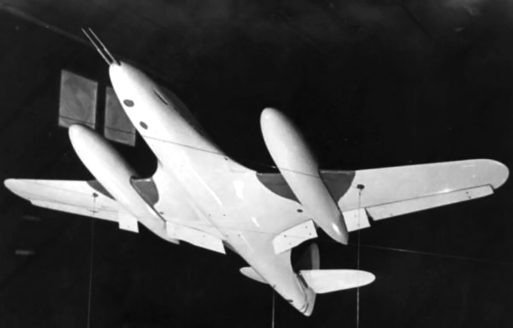
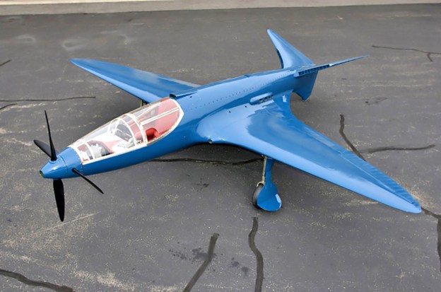
The elegant lines of the Bugatti 100P are well displayed in this image. (Hugh Conway Jr. image)

In 1936, Bugatti began to consider the possibility of building an aircraft around two straight eight-cylinder Bugatti T50B (Type 50B) engines, very similar to the engines that powered the Bugatti Grand Prix race cars. This aircraft would be used to make attempts on several speed records, most importantly, the 3 km world landplane speed record, then held by Howard Hughes in the Hughes H-1 Racer at 352.389 mph (567.115 km/h). Bugatti turned to Louis de Monge, a Belgian engineer, to help design the aircraft, known as the Bugatti Model 100P.

Bugatti 100P general arrangement drawing based off the original drawings by Louis de Monge. Note the arrangement of the power and cooling systems.

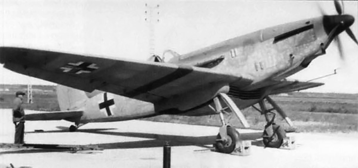
Before construction of the Bugatti 100P began, Germany demonstrated what if felt was its aerial superiority by setting a new 3 km world landplane speed record at 379.63 mph (610.95 km/h) in a Messerschmitt Bf 109 (V13) on 11 November 1937. Bugatti disliked Nazi-Germany and was very interested in beating their record. Bugatti and de Monge continued to develop the 100P for an attempt to capture the 3 km record from Germany.

The Bugatti 100P was one of the most beautiful aircraft ever built. With the exception of engine exhaust ports, the 25 ft 5 in (7.75 m) fuselage was completely smooth. The aircraft employed wood monocouque “sandwich” construction in which layers of balsa wood were glued and carved to achieve the desired aerodynamic shape. Hardwood rails and supports were set into the balsa wood to take concentrated loads at stress points, like engine mounts and the canopy. The airframe was then covered with tulipwood strips, which were then sanded and filled. Finally, the aircraft was covered with linen and doped. The Bugatti 100P stood 7 ft 4 in (2.23 m) tall and weighed 3,086 lb (1,400 kg).

The 100P had a 27 ft (8.235 m), one-piece wing that was slightly forward-swept. The wing had a single box spar that ran through the fuselage. The wing was constructed in the same fashion as the fuselage and housed the fully retractable and enclosed main gear. The wing featured a multi-purpose, self-adjusting flap system (U.S. patent 2,279,615). Both the upper and lower flap surfaces automatically moved up or down to suit the speed of the aircraft and the power setting (manifold pressure) of the engines. At high manifold pressure and very low airspeed, the flaps set themselves to a takeoff position. At low airspeed and low power, the flaps dropped into landing position, and the landing gear was automatically lowered. In a dive, the flaps pivoted apart to form air brakes.

Image of the nearly complete Bugatti 100P still under construction in Paris. The cooling-air inlet in the butterfly tail can be easily seen.

The Bugatti tail surfaces consisted of two butterfly units and a ventral fin at 120-degree angles (French patent 852,599). They were constructed with the same wood “sandwich” method used on the fuselage and wing. The tip of the ventral fin incorporated a retractable tail skid.  For cooling, air was scooped into ducts in the leading edges of the butterfly tail and ventral fin. The air was turned 180 degrees, flowed into a plenum chamber in the aft fuselage, and passed through a two section radiator (one section for each engine) located behind the rear engine. The now-heated air again turned 180 degrees and exited out the fuselage sides into a low pressure area behind the trailing edge of the wings. The high pressure at the intake and low pressure at the outlet created natural air circulation that required no fans or blowers (U.S. patent 2,268,183).

The two Bugatti T50B straight eight-cylinder engines were specially made for the 100P aircraft. The engine crankcases were made of magnesium to reduce weight, and each engine used a lightweight Roots-type supercharger feeding two downdraft carburetors. The T50B had a bore of 3.31 in (84 mm) and a stroke of 4.21 in (107 mm), giving a total displacement of 289 cu in (4.74 L). Twin-overhead camshafts actuated the two intake and two exhaust valves for each cylinder. The standard T50B race car engine produced 480 hp (358 kW) at 5,000 rpm. An output of 450 hp (336 kW) at 4,500 rpm is usually given for the 100P’s engines; however, de Monge stated the engines planned for the 100P were to produce 550 hp (410 kW) each. The engines were situated in tandem, behind the pilot. The front engine was canted to the right and drove a drive shaft that passed by the pilot’s right side. The rear engine was canted to the left and drove a drive shaft that passed by the pilot’s left side. The two shafts joined into a common reduction gearbox just beyond the pilot’s feet. The gearbox allowed each engine to drive a metal, two-blade, ground-adjustable Ratier propeller. Together, the two propeller sets made a coaxial contra-rotating unit. From the gearbox, the rear propeller shaft (driven by the front engine) was hollow, and the front shaft (driven by the rear engine) rotated inside it (U.S. patent 2,244,763).

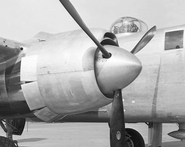
Image of the two T50B engines in the Bugatti 100P while at the Ermeronville estate. Note the radiator at left , how the engines are canted within the fuselage, and how the exhaust ports on the front engine protrude through the fuselage.

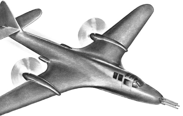
Once the new design was finalized in 1938, construction of the 100P was begun at a high quality furniture factory in Paris. While construction proceeded, it was obvious that war would break out soon. France did not have any fighters that could match the performance of their German counterparts. The French Air Ministry felt the 100P could be developed into a light pursuit or reconnaissance fighter and awarded a contract to Bugatti in 1939. This fighter was to be equipped with at least one gun mounted in each wing, an oxygen system, and self-sealing fuel tanks. Most aspects of the fighter are unknown, but it is possible that it was larger than the 100P and incorporated 525 hp (391 kW) T50B engines installed side-by-side in the fuselage driving six-blade coaxial contra-rotating propellers with a 37-mm cannon firing through the propeller hub. Because of France’s surrender, the aircraft never progressed beyond the initial design phase.

The Bugatti 100P, finally in all its glory after being completely restored by the Experimental Aircraft Association. Note the fairing for the rear engine ‘s exhaust ports above the wing. (Hugh Conway Jr. image)

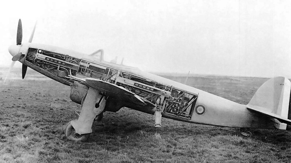
Bugatti’s contract included a bonus of 1 million francs if the 100P racer captured the world speed record which the Germans had raised to 463.919 mph (746.606 km/h) with a Heinkel He 100 (V8) on 30 March 1939 and raised again to 469.221 mph (755.138 km/h) with a Messerschmitt Me 209 (V1) on 26 April 1939. Bugatti and de Monge felt the 100P was capable of around 500 mph (800 km/h). In addition, a smaller version of the racer, known as the 110P, was planned; it featured a 5 ft (1.525 m) reduced wingspan of 22 ft (6.7 m). The 110P was to have the same engines as the 100P, but the top speed was estimated at 550 mph (885 km/h). However, other sources indicate these figures were very optimistic, and the expected performance was more around 400 mph (640 km/h) for the 100P and 475 mph (768 km/h) for the 110P.

The 100P was nearly complete when Germany invaded France. As the Germans closed in on Paris in June 1940, the Bugatti 100P and miscellaneous parts, presumably for the 110P, were removed from the furniture factory and loaded on a truck. The 100P was taken out into the country and hidden in a barn on Bugatti’s Ermeronville Castle estate 30 mi (50 km) northeast of Paris.

Bugatti 100P on display at the EAA AirVenture Museum in Oshkosh, Wisconsin. The cooling air exit slots on the left side of the aircraft can be seen on the wing trailing edge fillet. Also note the tail skid on the ventral fin.

Ettore Bugatti died on 21 August 1947 with the 100P still stashed away in Ermeronville. The aircraft was purchased by M. Serge Pozzoli in 1960 but remained in Ermeronville until 1970 when it was sold to Ray Jones, an expert Bugatti automobile restorer from the United States. Both Pozzoli and Jones offered the 100P to French museums but were turned down. Jones acquired the 100P with the intent to complete the aircraft; however, that goal could not be completed due to missing parts. Jones had the two Bugatti T50B engines removed from the airframe before everything was shipped to the United States. Dr. Peter Williamson purchased the airframe and moved it to Vintage Auto Restorations in Ridgefield, Connecticut in February 1971 to begin a lengthy restoration. Les and Don Lefferts worked on the project from 1975 to 1979. Louis de Monge was now living in the United States and assisted with some aspects of the restoration work before he passed away in 1977. In 1979, the unfinished 100P was donated to the Air Force Museum Foundation with the hope of having the restoration completed and the aircraft loaned to a museum for display. However, the aircraft sat until 1996 when it was donated to the Experimental Aircraft Association (EAA) in Oshkosh, Wisconsin and finally underwent a full restoration. The restored, but engineless, Bugatti 100P is currently on display at the EAA AirVenture Museum.

The original engines out of the Model 100P were reportedly not the final version of the engines intended for the actual speed record run. Both engines still exist and are installed in Bugatti automobiles. The front engine is installed in Ray Jones’ 1937 Type 59/50B R Grand Prix racer, and the rear engine is installed in Charles Dean’s 1935 Type 59/50B Grand Prix racer. Since January 2009, Scotty Wilson has led an international team, including Louis de Monge’s grand-nephew, Ladislas de Monge, to build a flying replica of the Bugatti 100P in Tulsa, Oklahoma. Piloted by Wilson, the Bugatti 100P replica flew for the first time on 19 August 2015. Tragically, Scotty Wilson was killed when the replica crashed during a test flight on 6 August 2016.

Bugatti 100P on display at the EAA AirVenture Museum in Oshkosh, Wisconsin. Simply one of the most beautiful aircraft ever built.

Sources:
The Bugatti 100P Record Plane by Jaap Horst (2013)
World Speed Record Aircraft by Ferdinand Kasmann (1990)
Airplane Racing by Don Berliner (2009)
The Classic Twin-Cam Engine by Griffith Borgeson (1979/2002)
http://www.bugattiaircraft.com/kalempa.htm by Alex Kalempa
http://www.airventuremuseum.org/collection/aircraft/2Bugatti Model 100 Racer.asp
http://www.airventuremuseum.org/collection/aircraft/2Bugatti Model 100 Racer Facts.asp
http://morlock68.pagesperso-orange.fr/bugatti.htm
http://bugatti100p.com/
http://en.wikipedia.org/wiki/Bugatti
http://kfor.com/2016/08/06/historic-replica-airplane-the-bugatti-100p-crashes-near-burns-flat-pilot-and-designer-scotty-wilson-dies/

Arsenal VB 10-02 under construction

Arsenal VB 10 Heavy Interceptor Fighter

By William Pearce

In January 1937, the Ministère de l’Air (French Air Ministry) gave Arsenal de l’Aéronautique a contract to develop a twin-engine heavy interceptor fighter built from wood and powered by two 690 hp (515 kW) Hispano-Suiza 12X engines. The engines were to be mounted in tandem inside the fuselage driving coaxial propellers in the nose. Through the course of several changes, the aircraft’s design was developed into the all-aluminum VB 10 fighter. The VB 10 was designed in 1938 by Michel Vernisse and Robert Badie; the initials of their last names formed the ‘VB’ of the aircraft’s designation.

Arsenal VB 10-01 rear

The Arsenal VB 10-01 prototype powered by two 860 hp (641 kW) Hispano-Suiza 12Y-31 V-12 engines. Note the obstructed rear view from the flush canopy.

The VB 10 was a low-wing monoplane in a standard taildragger configuration with retractable undercarriage and a single-seat. It was a large aircraft with a span of 50 ft 10 in (15.49 m), length of 42 ft 7 in (12.98 m), height of 17 ft 3/4 in (5.2 m), and an empty weight of 15,190 lb (6,890 kg).

While the aircraft was of a standard configuration, the engine arrangement was not. One engine occupied the standard position in the nose of the aircraft and a second engine was included behind the cockpit. Each engine drove a set of propeller blades that, together, made up a coaxial contra-rotating unit in the nose. The front engine drove the rear propeller, and the rear engine drove the front propeller. The drive shaft from the rear engine ran through the Vee of the front engine and to the front propeller. A Vernisse or homocinetic coupling was used in which flexibly-mounted ball joints join sections of the rear engine’s propeller shaft to accommodate deflection and vibration of the shaft.

Latecoere 299A runup

The Latécoère 299A that served as an engine testbed for the Arsenal VB 10. The 229A was powered by two 860 hp (641 kW) Hispano-Suiza 12Y V-12 engines, same as the VB 10-01 prototype. Note the front propeller is not turning and the German markings.

Before the prototype was built, a contract for 40 aircraft was placed in May 1940. However, construction was suspended with the capitulation of France in June 1940. In April 1942, the Vichy government was able to persuade the RLM (Reichsluftfahrtministerium or German Ministry of Air) to allow construction to resume on the twin-engine propulsion system. To thoroughly evaluate the unusual engine arrangement, a Latécoère 299 was made into a flying testbed and renamed 299A. Completed in July 1943, the Latécoère 299A was destroyed in an Allied bombing raid on 30 April 1944.

With the tide of the war changing, the French restarted construction of the first prototype, VB 10-01, in July 1944. The unarmed prototype was powered by two 860 hp (641 kW) Hispano-Suiza 12Y-31 12-cylinder, liquid-cooled engines and had a flush, sliding canopy with an obstructed rear view. This aircraft was first flown on 7 July 1945 by Modeste Vonner. During initial flight tests, the VB 10-01 achieved a sea-level speed of 304 mph (490 km/h). An order for 200 aircraft was placed on 22 December 1945.

Arsenal VB 10-02 under construction

The second prototype VB 10-02 under construction. Note the two 20 mm cannons and three .50-cal machine guns in each wing.

The second prototype, VB 10-02, had a bubble canopy for improved visibility and was powered by two 1,150 hp (858 kW) Hispano-Suiza 12Z engines. The aircraft was also armed with four 20 mm Hispano-Suiza cannons (with 600 rounds total) and six .50-cal Browning machine guns (with 2,400 rounds total), all mounted in the wings. The VB 10-02 first flew on 21 September 1946. Mechanical issues and engine overheating plagued both prototypes; these challenges, combined with the availability of cheap surplus allied aircraft and the jet age on the horizon, led to a revised order of just 50 aircraft.

Arsenal VB 10-02 side open

Another image of the Arsenal VB 10-02 with the side panels removed. Note the bubble canopy.

The first production VB 10 made its maiden flight on 3 November 1947. The aircraft was powered by two Hispano-Suiza 12Z-15/16 engines that were rated at 1,300 hp (969 kW) max and 1,150 hp (858 kW) continuous. It was armored with only four 20mm cannons but had provisions to carry one 1,100 lb (500 kg) bomb under each wing. Additional fuel took the place of the removed machine guns. The production aircraft went on to achieve a max speed of 323 mph (517 km/h) at sea-level and 435 mph (700 km/h) at 24,600 ft (7,500 m).

For the VB 10, the beginning of the end occurred on 10 January 1948 when the second prototype, VB 10-02, caught fire while over southern Paris. An uncommanded propeller pitch change over-reved the rear engine, destroying it and starting the fire. The pilot, Pierre Decroo, was forced to bail out. He survived but suffered burns. On 15 September 1948, the third (some say first) production machine crashed in much the same fashion, killing the pilot, Henri Koechlin. Six days later on 21 September 1948, the Arsenal VB 10 contract was cancelled. At the time of cancellation, four production VB 10 aircraft (including the one that crashed) had flown, six additional airframes had been completed, and a number of airframes were under construction. All remaining VB 10s (including the first prototype) were scrapped.

Arsenal VB 10 C-1 production

The size of the VB 10 is illustrated here by the crowd in front of the first production VB 10. The aircraft was powered by two Hispano-Suiza 12Z-15/16 engines. Note the 20 mm cannons and no machine guns.

Sources:
The Complete Book of Fighters by Green and Swanborough (1994)
Hispano Suiza in Aeronautics by Manuel Lage (2004)
Jane’s All the World’s Aircraft 1948 by Leonard Bridgman (1948)
– “Behind the Lines: French Development” Flight (3 February 1944)
http://fr.wikipedia.org/wiki/Arsenal_VB-10
http://en.wikipedia.org/wiki/Arsenal_VB_10
L’ Arsenal de l’Aéronautique by Gérard Hartmann (pdf in French)

McDonnell Aircraft Corporation Model 1

By William Pearce

In 1938 James McDonnell found himself diligently at work with the Glenn L. Martin Company in Baltimore, Maryland. While employed with Martin, McDonnell had designed a number of successful aircraft and was now focused on a streamlined design with the engine mounted in the fuselage. McDonnell had worked for the Martin Company since 1933 but was very interested in starting his own aircraft company. Late in 1938, he left Martin.

Artwork of the McDonnell Model 1 with a four-gun nose.

The McDonnell Aircraft Corporation was incorporated on 6 July 1939. The company began work out of St. Louis, Missouri and quickly obtained subcontracted work for other aircraft manufacturers. In addition, McDonnell submitted a few aircraft proposals to the United States Army Air Corps and Navy. Although none of the proposals led to any contracts, they did open the door for McDonnell to be included in the Air Corps Request for Data R40-C, officially issued on 20 February 1940.

R40-C was an informal Request for Data that encouraged aircraft manufacturers to propose unorthodox aircraft. These aircraft would need to be capable of at least 450 mph (724 km/h), but preferably 525 mph (845 km/h), and meet other requirements outlined in Type Specification XC-622. R40-C asked aircraft engine manufacturers to develop new power plants. A total of 26 aircraft designs were submitted by six selected aircraft companies. These designs included a mix of eight different engines from four engine companies. An additional engine from an additional manufacturer was later added.

Three-view general arrangement drawing of McDonnell’s Model 1 from November 1939. The drawing seems to illustrate a five-gun nose: two machine guns housed in the fuselage sides, two more (or cannons) toward the nose, and one cannon (possibly 37 mm) in the center of the nose.

McDonnell’s answer to R40-C was the Model 1 (often called Model I). It was the company’s first design, and McDonnell submitted its proposal to the Air Corps on 11 April 1940. Four Model 1 variations were submitted that differed only by engine type. While the Model 1 design appeared fairly conventional, it was possibly the most radical of the designs submitted. The Model 1’s shape was a direct evolution of concepts James McDonnell was working on during his last days with the Martin Company.

The Model 1 featured unprecedented streamlining and incorporated airfoil-shaped fillets where the wing and fuselage joined. The proposed engines were the 24-cylinder Allison V-3420-B2, 24-cylinder Pratt & Whitney H-3130, 24-cylinder Pratt & Whitney X-1800-A2G, and 42-cylinder Wright R-2160 Tornado; all were liquid-cooled. Regardless of the type selected, the engine was buried in the fuselage aft of the pilot. Engine power was transmitted via extension shafts and right angle gear drives to a pair of two-speed, four-blade, 10 ft 7 in (3.23 m) diameter, pusher propellers mounted on the wings. The aircraft featured gear-driven radiator cooling fans. Originally the aircraft was to be armed with two .30-cal. machine guns and two 20 mm cannons, but armament varied throughout the design process. However, armament always consisted of a combination of two to four machine guns and one to four cannons.

Allison V-3420-powered McDonnell Model 1 cutaway dated April 3, 1940. Armament now includes six guns: two machine guns in the fuselage sides, two more (or 20 mm cannons) toward the nose, and two 20 mm cannons in the nose.

The X-1800 and R-2160-powered designs did not meet the specifications of XC-622 and were dropped from the R40-C competition.  With a two-stage supercharger for the V-3420 engine and a two-stage, two-speed supercharger for the H-3130, both engines provided sufficient power for their respective Model 1 designs to achieve the XC-622 specifications.

The Model 1 had a 45 ft (13.7 m) wingspan and was 45 ft 4 in (13.8 m) long. With the Allison V-3420, the aircraft weighed 13,826 lb (6,271 kg) and had a maximum speed of 383 mph (616 km/h) at 5,000 ft (1,524 m) and 448 mph (721 km/h) at 20,000 ft (6,096 m). With the Pratt & Whitney H-3130, the Model 1 weighed 14,800 lb (6,713 kg) and had a maximum speed of 385 mph (620 km/h) at 5,000 ft (1,524 m) and 454 mph (731 km/h) at 20,000 ft (6,096 m).

mcdonnell-model-1-tractor-flaps

This wind tunnel model illustrates the evolution of the Model 1 as it became the XP-67. Seen here is the Model 2, with wing-mounted Continental XI-1430 engines in a tractor configuration. The basic shape of the Model 1’s fuselage and wings remained unchanged. The next version, known as the Model 2A, incorporated significant blending of the fuselage and engine nacelles with the wings. The Model 2A was the final step to the XP-67. (Image is flipped as the model was actually hung inverted in the wind tunnel.)

It would take an estimated 42 months to develop the engine and power drives for the Model 1. In addition, the Model 1 was the heaviest aircraft in the competition. These and other factors resulted in the two remaining Model 1 proposals to be ranked 21st and 22nd out of 26 submissions. Even so, the Model 1 did interest the Air Corps enough for them to purchase engineering data and a wind tunnel model on 6 June 1940 for $3,000. This was the McDonnell Aircraft Corporation’s first sale to the Army Air Corps.

The new engines involved with the R40-C competition became known as the “hyper” engines, an abbreviation of high-performance. The aircraft that won the competition were the Vultee XP-54 Swoose Goose, Curtiss XP-55 Ascender, and Northrop XP-56 Black Bullet. All were built and were pusher designs that failed to meet expectations and were fraught with technical difficulties. None of the hyper engines or R40-C aircraft entered production. The Model 1 was developed into the McDonnell XP-67 Moonbat that, although not successful, was built and did fly.

McDonnell Aircraft Corporation ad featuring the Model 1.

Sources:
American Secret Pusher Fighters of World War II by Gerald Balzar (2008)
McDonnell Douglas Aircraft Since 1920: Volume II by Rene Francillion (1990)
American Secret Projects 1937–1945 by Tony Buttler and Alan Griffith (2015)
– “Design for a Pursuit Airplane” U.S. Design Patent 134,425 by James McDonnell (1942) pdf

Douglas XA-26D 41-39543

Douglas XA-26D and XA-26E Invaders

By William Pearce

The Douglas XA-26D and E were improved versions of the Douglas A-26B and C respectively. Both the XA-26D and E were upgraded with a more powerful version of the Pratt & Whitney R-2800 radial engine, the -83, built by Chevrolet and rated at 2,100 hp (1,566 kW). The engine’s output increased to 2,400 hp (1,780 kW) with water injection. The carburetor air scoops in the cowling were revised along with the carburetors, superchargers, engine mounts, and generators. The aircraft were fitted with wide-cord, 12.7 ft (3.87 m), four-blade propellers with spinners, although three-blade propellers were also tested. The top speed of the XA-26D and E was 403 mph (649 km/h) at 15,000 ft (4,572 m)—about 50 mph (80 km/h) faster than the B and C models—and the climb rate doubled to 2,326 fpm (11.8 m/s).

Douglas XA-26D 41-39543

The second XA-26D Invader, serial number 41-39543, is seen here with three-blade propellers. Note the spinners and revised engine cowlings compared to a typical A-26.

The D model was a solid nose version primarily intended for ground attack. The aircraft was equipped with 14 forward-firing .50-cal. machine guns: eight in the nose and six more in the wings. The aircraft also had dorsal and ventral barbettes with two machine guns each.

The first XA-26D Invader was modified from an A-26B, serial number 44-34100, starting in January 1945. Serial number 44-34100 was accepted by the USAAF on 31 January 1945 but was not available until 31 October 1945. The individual aircraft record card has a notation indicating the aircraft was to remain at the contractor’s plant for 180 days. The first record entry listing the aircraft as an A-26D was on 11 November 1945. Another XA-26D was created using A-26B serial number 41-39543, and the D modifications were completed by July 1945.

Some sources list another A-26B, serial number 44-34776, as being converted to the XA-26D standard. However, the data card for this aircraft makes no reference to a conversion program.

One B-26C, serial number 44-35563, was modified by the Douglas plant to XA-26E specifications. The E model was the glass nose version with two machine guns in the nose, six in the wings, and two in each dorsal and ventral barbettes.

A contract for 750 production A-26Ds was placed on 13 April 1945, following an order of 1,250 A-26Es placed on 5 April 1945. Both contracts were cancelled at the end of World War II; none of the aircraft were built.

Douglas XA-26D 41-39543 4-blade

The second XA-26D aircraft with four-blade propellers. Note the first Douglas XB-42 Mixmaster prototype at left in the background.

Sources:
American Bomber Aircraft Development in World War 2 by Bill Norton (2012)
http://www.nationalmuseum.af.mil/factsheets/factsheet.asp?id=3067
http://www.nationalmuseum.af.mil/factsheets/factsheet.asp?id=3149

NA-98X Front

North American Aviation NA-98X Super Strafer

By William Pearce

In 1943, North American Aviation (NAA) created an internal design for an improved attack bomber that would provide the firepower of the B-25H but with substantially improved performance. This evolution of the B-25 line was intended as an alternative to the heavily-armed and delayed Douglas A-26B Invader. Power was to be provided by a pair of Pratt & Whitney R-2800 air-cooled radial engines housed inside low-drag cowlings and driving a pair of cuffed, four-blade propellers with spinners. The empennage was changed to a conventional single-tail, altering one of the B-25’s most notable characteristics. The wing tips were square-cut like a P-51’s, rather than rounded, permitting the ailerons to be extended farther outboard to provide better roll control. Armament improvements were to include a computing gun sight and a new low-drag canopy designed by North American for the top turret. A compensating sight was to be used in the tail turret and illuminated reflector optical sights for the waist guns. Otherwise, the aircraft had the same armament as the B-25H, including the 75mm cannon.

NAA B-25 based high performance attack bomber drawn by Eugene Clay.

In early 1944, a low-cost and less ambitious alternative was submitted to the Army Air Forces. This proposal was to take the existing B-25 airframe and apply many of the enhancements from the NAA internal design. A B-25H-5 (serial number 43-4406) was chosen as a testbed for the modifications, which no longer included the single tail and four-blade propellers. It was given the designation NA-98X by NAA and nicknamed Super Strafer. Since it was not designed for any USAAF requirement, it never carried an official USAAF designation.

The new aircraft was powered by a pair of 2,000 hp (1,491 kW) Pratt & Whitney R-2800-51 engines with 15 minutes of water injection, all housed in A-26 cowlings. Large conical spinners were used on the three-blade propellers. The squared wing tips allowed the ailerons to be extended by one foot, and the control system was changed to lighten the stick forces. Except for the removal of the fuselage blister gun packs, the aircraft had the same armament as the B-25H.

The NA-98X: a B-25H, serial number 43-4406, modified with R-2800 engines, spinners, and squared wings.

The first flight of the NA-98X took place at Mines Field in Los Angeles on 31 March 1944. NAA test pilot Joe Barton was at the controls with Jim Talman as the NAA flight engineer. The flight lasted an hour, and Barton reported better speed and acceleration, reduced vibration, and a higher roll rate compared to a standard B-25. The Super Strafer performed well. The aircraft reached 10,000 feet (3,048 m) in 4.9 minutes at war emergency power and in 5.3 minutes at military power. A maximum speed of 328 mph (528 km/h) was achieved at sea level with war emergency power, and Barton eventually achieved 350 mph (563 km/h) at a higher altitude. The performance numbers were a drastic improvement over the standard B-25H’s top speed of 273 mph (439 km/h) and 790 fpm (4.0 m/s) climb rate. There were 16 more NAA test flights before the aircraft was turned over to the USAAF for evaluation.

The increased power of the R-2800 engines, along with the increased aileron area and reduced stick forces, created the possibility to operate the aircraft outside the structural limits of the wings. This could lead to a catastrophic failure, loss of the aircraft, and possible loss of life. Without strengthening the wings for intended dives of 400 mph (644 km/h) and high-g pullouts, the maximum airspeed was restricted to 340 mph (547 km/h), and a g-limit of 2.67g was imposed during flight tests.

NAA NA-98X cowling

A detailed look at the A-26 cowling covering the R-2800 engine installed on the NX-98X.

Major Perry Ritchie was assigned as the evaluator for the USAAF and had made 13 flights in the aircraft before disaster struck on 24 April 1944. Returning from the aircraft’s 29th test flight, Maj. Ritchie and Lt. Winton Wey approached Mines Field at a very high speed, above the 340 mph (547 km/h) redline. As he made a steep pull-up, in excess of the 2.67g restriction, both wings separated outboard the engine nacelles and struck the horizontal stabilizers, causing the tail to break free from the aircraft. The NA-98X crashed, killing both Maj. Ritchie and Lt. Wey.

The NA-98X was a very powerful and responsive aircraft. Maj. Ritchie was primarily a fighter pilot and had a tendency to fly the maneuverable bomber more like a fighter. Maj Ritchie had made the high-speed pass and abrupt pull-up twice before and was warned not to do it again. Some eyewitnesses estimated that the NX-98X made the last pass at around 400 mph (644 km/h) and hit around 5g in the pull-up. Simply put, the aircraft was flown beyond its known structural limitations by Maj. Ritchie.

Following the crash, all further work on the NA-98X project was abandoned even though the RAF had shown interest after a test flight. Admittedly, the wings would have required a redesign to cope with the power from the R-2800s, negating any cost savings for performance on par with the Douglas A-26. In its short 25-day life, the NA-98X Super Strafer totaled 40:15 hours of flight tests. NAA time totaled 21:25 hours over a period of 22 days, including eight days of down time. Total time for Maj. Ritchie was 18:50 hours over a period of three days.

NA-98X Front

Front view of the NA-98X Super Strafer with the 75mm cannon and squared wingtips clearly visible.

Sources:
– “North American B-25 Variant BriefingWings of Fame Volume 3  (1996)
American Bomber Aircraft Development in World War 2 by Bill Norton (2012)
North American Aircraft 1934-1998 Volume 1 by Tom Avery (1998)
http://www.joebaugher.com/usaf_bombers/b25_16.html
http://www.warbirdinformationexchange.org/phpBB3/viewtopic.php?t=31406&view=previous

Dreadnought at speed

One Second on the Course with Dreadnought – by Tom Fey

At a race weight of 6.25 tons, the trick Pratt & Whitney R-4360-63 powered T.20 Sea Fury “Dreadnought” is truly the big kid on the air racing block. Built, owned, and flown by the late Frank and sons Brian and Dennis Sanders, this two-seat masterpiece has turned the pylons as fast as 458.9 mph by virtue of the clean, highly detailed airframe and the 3,800 horses that tread within her custom cowling. Dreadnought has won the National Championship Reno Air Races twice, and finished second 13 times. To simply call this airplane large and fast, while certainly accurate, diminishes the fantastic complexity required to attain such impressive performance. If you could examine a single second of time while Dreadnought is hard at work, engine at 3000 rpm and 72 inches of manifold pressure, just 70 feet off the deck at 450 mph on the Reno course, what would you find?

Dreadnought at speed

Brian and Dennis Sanders’ Pratt & Whitney R-4360 powered Hawker Sea Fury, Dreadnought.

In that one second, the thundering, 4,290 lb R-4360 radial has gone through 50 revolutions, with each of the 28 finely-finned cylinders firing 25 times. Inside each cylinder of 156 cubic inch (2.6L) displacement (same as the entire V-6 powerplant in a C class Mercedes-Benz) a piston the diameter of a coffee saucer has transmitted close to 140 horsepower to the master rod. Seven cylinders drive each crankpin through one master and six link rods, with each of the four crankpins transmitting 900+ horsepower to the crankshaft. Seven hundred power pulses, one pulse for each 9.5° of propeller arc, have been transmitted to the six foot long, one-piece, forged, four throw steel crankshaft. Each piston has traveled 50 feet in linear distance, changing direction 100 times per second, with the total linear travel of all 28 pistons adding up to a ¼ mile. Each sodium-filled exhaust valve the diameter of a beer can (2.5 inches) has required 2.1 tons of initial force to open the port to expel the 1600° F gasses into the 14 exhaust stacks specifically choked to maximize jet thrust from the exhaust. The single-stage supercharger rotor, 14 inches in diameter, has spun 348 times, delivering 98 cubic feet of air at 72 inches of manifold pressure, equivalent to 21 psi above ambient pressure. Seven intake trunks, 2.75 inches in diameter, undulate forward from the supercharger housing to supply the compressed mixture to the intake valves perched atop the forged aluminum heads. The pressure within each cylinder will approach 235 psi before the four, low tension magnetos on the nose case supply the 1400 sparks per second, 20,000+ volts per spark, to the 56 individual spark plugs that fire off the charge.

In that one second, almost 14 fluid ounces of 115/145 performance number aviation  gasoline have been injected into the gaping Bendix PR-100 carburetor with an intake throat the size of a tool box. Five fluid ounces of anti-detonant water/methanol mixture have been force-fed into the intake system to assure the supercharged mixture, heated by compression, does not exceed 194°F, thereby moderating the charge to burn at the proper rate and at a sub-solar temperature. More than 12,408 BTU’s of heat energy (3.1 million calories) have been released into the engine, enough to raise the temperature of a 55 gallon drum of water 27° F. Approximately 8.6 fluid ounces of water has been sprayed at 35 psi from 14 nozzles placed in the narrow, 3.75 inch gap of the cowling inlet to atomize the fluid and dissipate heat directly from the otherwise air-cooled cylinders. In that thousand milliseconds, approximately 60 lbs of cooling air have entered through the three square feet of inlet area (area of a pizza box), its temperature raised 45° F by ram pressure alone, then cleverly guided by a tapered spinner afterbody, shrouds, hoods, and baffles to flow across the four rows of seven cylinders, expand across the engine, absorb heat, and exit the cowling exhaust chute.

Dreadnought takeoff

Installation of the R-4360 required a longer cowling to cover the engine and a taller tail to counteract torque.

In that one second, tucked inside the forged aluminum R-4360 nose case, 10 hefty steel planet gears, an inch thick with 23 teeth each, caged in the propeller reduction unit, have spun on their own plain bearings 50 times and orbited inside the ring gear close to 19 times to slow the speed of the propeller relative to the engine. The 13.5 foot diameter, four-bladed Aeroproducts propeller and regulator, some 528 pounds altogether, have made 18.75 revolutions, the tips arcing through 795 feet of linear distance and subjected to 2700 times the force of gravity. Each furnace-brazed, hollow steel propeller blade has a chord (width) of 15 inches and sports a custom contour at the outer trailing edge to reduce tip load vibration as it strains to efficiently convert 900 horsepower into thrust, speed, and victory.

In that one second, the 2 pressure oil pumps have sent 148 fluid ounces, almost 1.2 gallons, of 60 weight, W120 aviation oil at 90 psi through the engine to lubricate and cool the reciprocating symphony, while seven scavenge pumps have collected the oil, circulated it through the dual oil coolers, and back to 30 gallon oil tank. A lonely tablespoon of oil has escaped past the piston rings, burned, and been blown overboard.  Approximately 4.3 fluid ounces of spray bar water have been ejected from 56 ports at 15 psi.; 14 pairs of diametrically opposed ports for each of the two oil coolers, one cooler tucked into each wing root. The spray bar water is directed onto metal tabs welded to the stainless steel spray bar tubing, fracturing the stream and turbulating the mist, essential for removing 270 BTUs of heat per second from the oil.

Dreadnought and Rare Bear

Dreadnought and Rare Bear on the course at Reno in 2012.

In that one second, over 1.72 million, yes million, foot/lbs of work have been done, enough to raise a 150 lb. man 2.2 miles into the air or lift a 60 ton Abrams battle tank through a football goal post. The mighty aircraft has covered 660 feet, roughly 1.5% of the current 8.48 mile Reno Unlimited course. Each second approximately 2 lbs of fluids are consumed and ejected, reducing the racer’s 45 lbs per square foot takeoff wing loading by 10% at touch down. In that single second, coming off Pylon 6, g force easing, wings almost level, the pilot begins a quick scan of the 9, 2.5 inch diameter analog gauges essential for racing (induction temperature, cylinder head temperature, oil temperature, oil pressure, torque pressure, cylinder head temperature, anti-detonant injection pressure, cylinder cooling spray pressure, fuel flow, oil cooler spray bar pressure, spray bar pressure, oil cooler door position indicator) aligned across the top 2 rows of the panel. The wide eyed but extremely focused pilot, Brian or Dennis Sanders, dodging dust devils, scanning the sky for aircraft and the ground for their shadows, is reassured to find all is well within the thundering juggernaut as it rat races over the mile high desert outside Reno, Nevada.

In just one second of the 535 seconds it takes to complete the 66.9 mile race, man and machine, wind and air, water and oil, speed and gravity, combine to make air racing the most elite motorsport of all. Despite engines and airframes that haven’t been manufactured since 1960, Unlimited-class air racing remains the World’s Fastest Motor Sport, and an experience of sight and sound unique in all of racing. Long live the big iron.

Dreadnought R-4360

With the cowling removed one can see the tight fit of the R-4360 and the baffles to direct the cooling air over the cylinders.

My thanks to Brian Sanders, Graham White, Pete Law, Bill Pearce, and Hewlett-Packard for their expert and most welcome assistance. – © Tom Fey  8-28-06

One hundred twenty-four seconds on the course with Dreadnought, qualifying for Reno at 449.357 mph in 2009, are captured in the video below. The video was uploaded by warbirdphotos and taken from the Valley of Speed. The vapor seen trailing the aircraft is from the spraybars.