Yearly Archives: 2013

Menasco Unitwin rear

Menasco 2-544 Unitwin Aircraft Engine

By William Pearce

Albert (Al) S. Menasco got his start in the aircraft engine business in 1926 when he was tasked with settling the estate of his friend Art Smith. Before he passed, Smith had purchased 250 Salmson Z-9 water-cooled 9-cylinder radial engines. Waldo Waterman approached Menasco with an idea to convert the Salmson engines to air-cooling. Menasco ended up progressing on his own with the project and made further modifications to the Salmsons. Despite his best efforts, Menasco could not make the Menasco-Salmson B-2 engine reliable enough to pass the new Department of Commerce’s 50-hour test.

Menasco Unitwin front

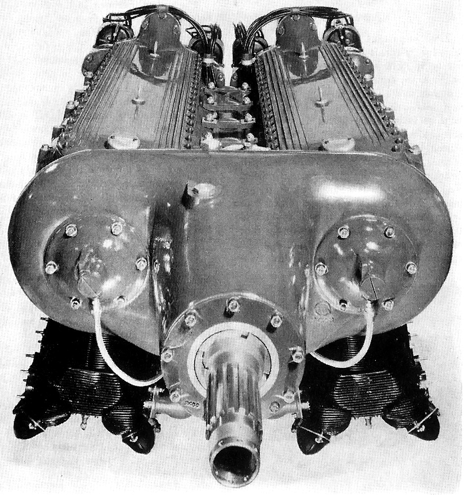
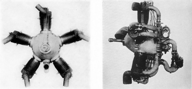
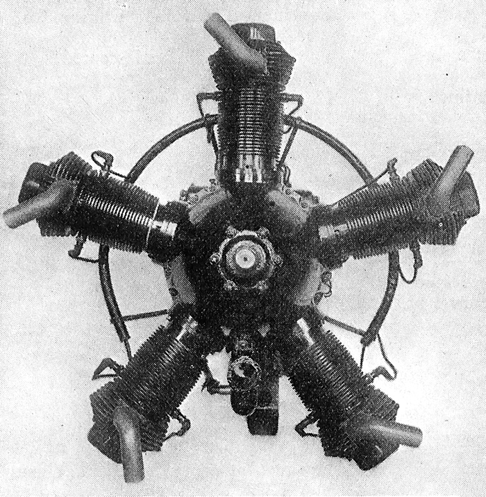
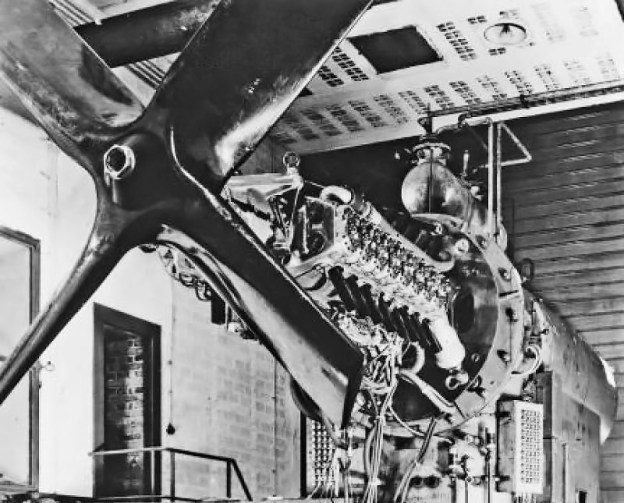
This front view of the Unitwin illustrates the slight contrary angle of the Buccaneer engine sections. Visible are the brackets that bolt the two crankcases together to make the Unitwin more rigid. Note the oil supply lines on each side of the gear case for spraying oil on the freewheeling clutches.

In 1928, Menasco found himself with a good shop and a good crew but no engine to manufacture. Jack Northrop was visiting Menasco one day and suggested he should build an inverted, in-line, air-cooled, four-cylinder aircraft engine. This was the start of the 90 hp (67 kW) four-cylinder Menasco Pirate engine and quickly led to the 160 hp (119 kW) six-cylinder Menasco Buccaneer in 1931. Remembering the troubles with the Salmson, Menasco designed these engines to run at 125% rated power for 100 hours straight. The Pirate and Buccaneer were very popular and very successful engines with air racers. Over years of continued development, the engines were supercharged and their output increased to 150 hp (112 kW) and 260 hp (194 kW) respectively.

In mid-1935, Robert Gross, Cyril Chappellet, and Hall Hibbard discussed with Menasco the possibility of coupling two six-cylinder Buccaneer engines together side-by-side to make an inverted U-12 engine. Gross, was the President of the Lockheed Aircraft Corporation, Chappellet its corporate secretary, and Hibbard its chief engineer. Menasco thought the Buccaneer could be developed to produce 350 hp (261 kW), giving the coupled engine 700 hp (522 kW). Through freewheeling (or overrunning) clutch mechanisms, the two engines would power a single propeller. If one engine were to fail, the other would be unaffected and continue to power the constant-speed propeller. The propeller’s pitch would change to compensate for the decrease in power. This arrangement would give twin-engine reliably without the drag of a conventional twin-engine installation or the asymmetric thrust during an engine failure. The men from Lockheed thought the engine would be well suited to power personal aircraft or small feeder aircraft for airline service.

Menasco Unitwin

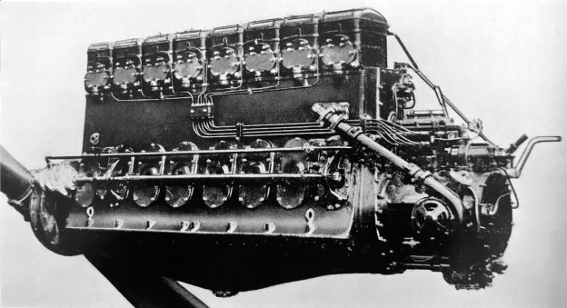
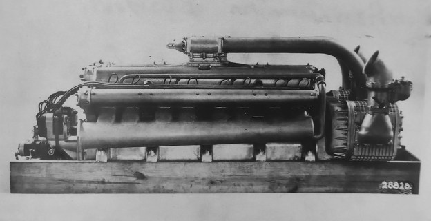
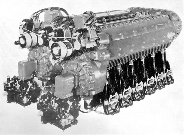
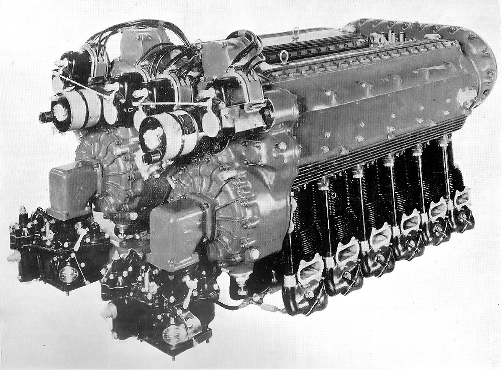
The Menasco Unitwin engine with the air-cooling baffles in-place. Note the intake manifold: on a standard Buccaneer engine, this manifold was on the opposite side. On the Unitwin, both engine sections had the intake manifold on the outside of the engine. Note the revised oil lines to the gear case compared with the previous image.

In 1936 and with Lockheed sponsorship, Menasco coupled two 90 hp Wright Gipsy four-cylinder engines to test the feasibility of a freewheeling gear case. This coupled engine endured 300 hours of tests and paved the way for the Menasco Unitwin. Lockheed formed a new subsidiary, the Vega Airplane Company (originally the AiRover Company), to manufacture an aircraft powered by the Unitwin. In addition, Lockheed explored the possibility of installing Unitwin engines in its Model 12 Electra Junior. By 1937, Vega had taken over the Unitwin project which was behind schedule. Issues were encountered with the Buccaneer engine being able to produce the desired 350 hp (261 kW) output. In addition, the Menasco Manufacturing Company was in poor financial health. Lockheed’s Gross and Chappellet personally invested in Menasco to keep the company going.

The Menasco 2-544 Unitwin was comprised of two 544 cu in (8.9 L) C6S-4 Super Buccaneer six-cylinder engines. The Buccaneer  engines were positioned side-by-side and coupled together by a common gear case. Each engine was canted out 10-degrees from vertical. The gear case housed hydraulic freewheeling clutches that allowed the engines to be operated completely independent of each other. In addition, the rear of the gear case had provisions to run essential accessories, including the prop governor and an oil pump. The gear case had its own oil supply, independent from the engine sections. The engine sections were modified to rotate opposite the normal direction, and once through the gear case, rotation returned to normal for the use of a standard propeller. The gear case also incorporated a 0.667 (may have been 0.6375) propeller gear reduction.

Menasco Unitwin rear

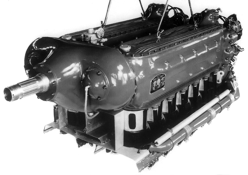
Rear view of the Menasco Unitwin showing the separate superchargers, carburetors, magnetos, and starters.

Rigid supports connected the two Buccaneer crankcases together to utilize one engine mount. The two rows of cylinder shared baffles to direct the cooling air through their fins. Later in development, the intake and exhaust on the left engine section were reversed; this allowed the intake manifolds to travel along the outside of both engine sections and for the exhaust manifolds to be located in the middle, between the sections.

The inverted U-12 had a 4.75 in (121 mm) bore and a 5.125 in (130 mm) stroke. Total displacement was 1,090 cu in (17.9 L). Each cylinder had one intake and one exhaust valve actuated by pushrods. Two spark plugs per cylinder were fired by Scintilla magnetos, two on each engine section. The compression ratio was 5.5 to 1, and each engine section had its own supercharger. The engine produced 580 hp (433 kW) at 2,400 rpm and had a maximum output of 660 hp (492 kW) at 2,700 rpm. The Unitwin was 80.0 in (2.0 m) long, 38.0 in (1.0 m) wide, and 30.5 in (0.8 m) tall. The engine weighed 1,380 lb (626 kg).

Other Unitwin gear case and engine configurations were considered. One gear case design raised the propeller shaft above the engine. With a hollow propeller shaft, this would allow a machine gun or cannon to be mounted above the engine with its barrel projecting through the propeller shaft. This design was intended for military use, but it is unlikely that it was ever built. A different engine configuration arranged the cylinders horizontally, to create a “flat” engine for installation buried in an aircraft’s wing. This engine configuration was never built.

Vega Altair Unitwin

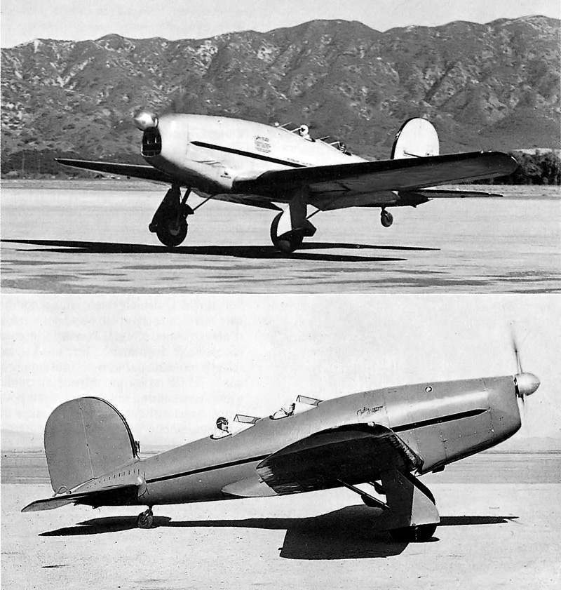
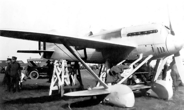
Two views of the Vega-built Altair serving as a testbed for the Manasco Unitwin.

While the Unitwin was undergoing stringent bench tests to prove its reliability, Vega (AiRover) assembled a Lockheed Altair 8G (registered NX18149) from spare parts to serve as a flying testbed for the engine. This aircraft was the AiRover/Vega Model 1 and was also called the Flying Test Stand. The Unitwin-powered Altair first flew on 29 June 1938. In this aircraft, the Unitwin was put through its paces. One engine section would run at a steady power while the other was throttled quickly between full open and closed. With one engine’s throttle sealed closed, the Altair took off and climbed to 12,000 ft (3,658 m) without aircraft stability or engine cooling issues. However, the Menasco Manufacturing Company’s financial issues continued to worsen, and Gross and Chappellet essentially took over the company. This resulted in Al Menasco leaving the company in June 1938.

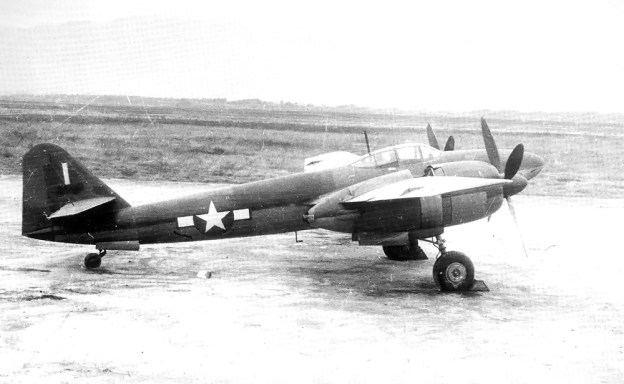
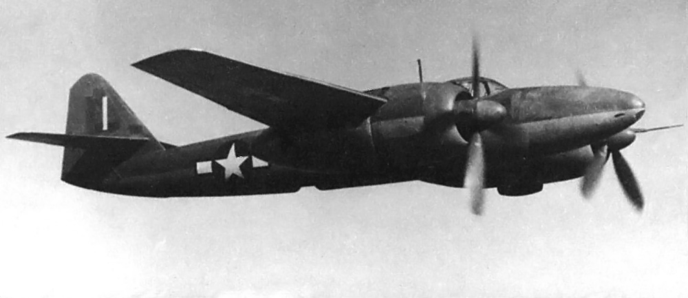
Encouraged by the results of the Unitwin in the Altair, Vega built a five to six place aircraft around the engine. Vega president, Mac Short, oversaw the design of this aircraft, known as the Vega Model 2 Starliner (registered as NX21725). The Starliner was meant to appeal as a feeder airliner and an executive and personal transport aircraft. Its first flight, on 22 April 1939, ended in an emergency landing when the propeller slipped into fine pitch. The pilot (Vern Dorrell) and observer (J. B. Kendrick) were uninjured, and the Starliner escaped with only minor damage.

Vega Starliner

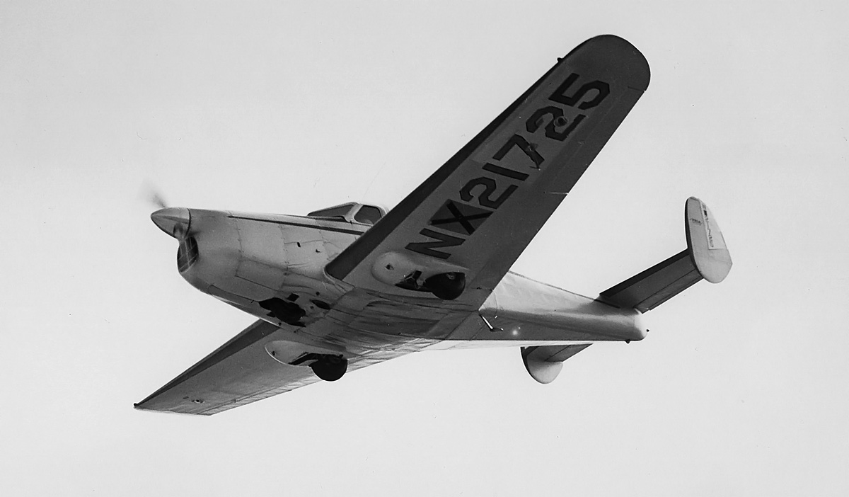
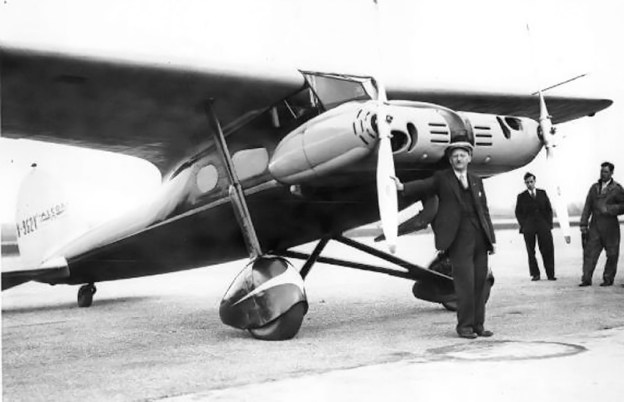
The two-piece windscreen and twin tails of the Vega Starliner gave it a similar appearance to contemporary Lockheed transports.

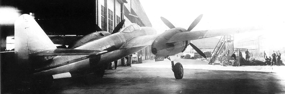
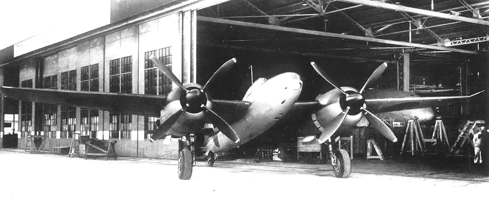
The aircraft was originally built with twin tails. While it was being repaired, a single, conventional tail replaced the twin fins, and the rear of the fuselage was modified. The Starliner was soon back in the air but was later damaged again when the nose gear would not extend for landing. The aircraft was repaired again, but Vega was becoming increasingly occupied with government contracts. In addition, Vega realized the Unitwin would never be able to produce 700 hp (522 kW) and that the Starliner was too small for feeder line service. One aircraft was ordered by Mid-Continent Airlines, but this order was later cancelled.

After amassing 85 hours of flight time, Starliner development was discontinued. The airframe was sold off as a Hollywood prop. Although the Unitwin engine operated without issues and performed as designed, it had no prospects beyond the Starliner. Menasco Manufacturing Company, like Vega, was receiving a flood of government contracts; therefore, Unitwin development was halted in 1940. There are no known surviving examples of this engine.

Vega Starliner single tail

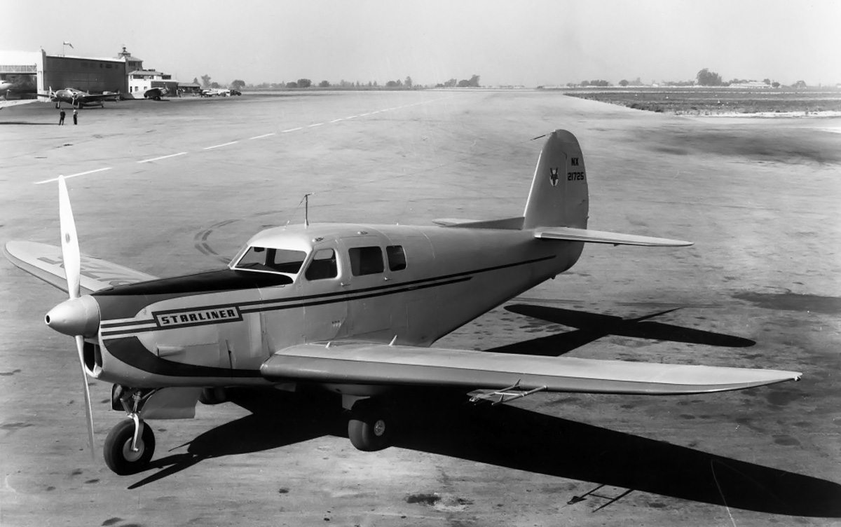
The Menasco Unitwin-powered Vega Starliner with a single tail. Note the updated paint job with “Starliner” on the engine cowl.

Sources:
– “Unitwin Power Plant” by Mac Short, Aero Digest (February 1939)
Aerosphere 1939 by Glenn Angle (1940)
Race With the Wind by Birch Matthews (2001)
Jane’s All the World’s Aircraft 1940 by C. G. Grey and Leonard Bridgman
Multiple Motor Drive for Aircraft Propellers US patent 2,284,473 by Albert S. Menasco and Hall L. Hibbard (granted 26 May 1942)
Multiple Motor Drive US patent 2,180,599 by Albert S. Menasco (granted 21 November 1939)
Lockheed Aircraft since 1913 by Rene J. Francillon (1982/1987)
The Menasco Story by Ralph J. Schmidt (1994)
– “Menasco Aircraft Engines and their Air Racing Heritage, Part 1” by Larry M. Rinek, Torque Meter Vol. 2 No. 4 (Fall 2003)
Waldo: Pioneer Aviator by Waldo Dean Waterman with Jack Carpenter (1988)

Republic XP-47J front

Republic XP-47J Superbolt Fighter

By William Pearce

In mid-1942, Republic Aviation Corporation initiated a design study to lighten their P-47 Thunderbolt fighter for improved performance. The Thunderbolt had been steadily gaining weight as the design matured, while comparative enemy aircraft, like the Focke-Wulf FW 190A, were much lighter. Republic officially proposed a light-P-47 to the Army Air Force (AAF) on 22 November 1942. On 1 April 1943, the AAF gave Republic a letter of intent to purchase two light-weight P-47s, and the contract was officially approved on 18 June 1943. This new aircraft was designated the XP-47J.

Republic XP-47J front

An early image of the Republic XP-47J before the Superman nose art was applied. Note the cooling fan vanes around the spinner inside the cowling.

As with all P-47s, Alexander Kartveli was the main designer of the XP-47J, and he was assisted by Murray Burkow. The XP-47J was similar in appearance to a P-47B, but it was a completely new aircraft. The XP-47J had a close-fitting cowl installed around its Pratt & Whitney (P&W) R-2800 engine of increased power output. A large spinner was added, along with a fan to aid engine cooling. The turbosupercharger’s intake had been refined, and the flow of its exhaust was directed to provide additional thrust. Two of the .50-cal machine guns were deleted (leaving six) in the XP-47J’s lightened wing, and the rounds per gun were reduced to 267. Other weight-saving measures were the omission of radio equipment and the aft fuel tank. To keep the aerodynamics clean, the XP-47J had no provisions for external stores under the wings or fuselage.

Originally, the AAF wanted the XP-47J to have contra-rotating propellers and a bubble canopy, like a late P-47D. To expedite the XP-47J, the decision was made for the first prototype to be a razorback version and the second prototype would include a bubble canopy. The six-blade contra-rotating propeller was test-flown on a P-47B but showed no increase in performance. This, combined with delays at P&W on the R-2800-61 engine with a contra-rotating gear reduction, resulted in the substitution of a R-2800-57 engine with a standard gear reduction. Both the -57 and -61 engines were rated at 2,100 hp (1,566 kW) and had a War Emergency Power (WEP) rating of 2,800 hp (2,088 kW). The -61 engine would be supplied later, when it was available. The engine, cowling, and cooling fan were installed and test flown on a P-47D-15.

Republic XP-47J right

This side view of the XP-47J reveals its distinct intercooler air and exhaust exits under the rear fuselage.

The XP-47J had a wingspan of 40 ft 10 in (12.4 m) and a length of 33 ft 3 in (10.1 m). The aircraft had an empty weight of 9,663 lb (4,383 kg) and a design gross weight of 12,400 lb (5,625kg). Its service ceiling was 45,000 feet (13,716 m). The XP-47J had a range of 765 mi (1,231 km) at a cruising speed of 400 mph (644 km/h) and a range of 1,070 mi (1,722 km) at optimum cruising speed. Fuel capacity was 287 US gal (1,086 L).

On 31 July 1943, Republic issued a report comparing the estimated performance of the XP-47J with the P&W R-4360-powered XP-72 that was under development. The report concluded that the Republic XP-72 had more potential and recommended resources be focused on that aircraft. In addition, 70% of the P-47 production line needed to be re-tooled in order to produce the P-47J. Republic called for the cancellation of the second XP-47J prototype but encouraged the completion and testing of the first prototype. The AAF approved Republic’s plan and cancelled the second XP-47J.

The sole XP-47J prototype (serial number 43-46952) was completed in mid-November 1943 and made its first flight on the 26th of that month. The aircraft was quickly dubbed Superbolt and wore nose art on both sides of the cowling of Superman holding a lightning bolt. After about 10 hours of flying time, the R-2800-57 engine was making metal and was replaced by another engine of the same type in February 1944.

Republic XP-47J run-up

The factory-fresh Superbolt is being run-up outside of Republic’s plant in Farmingdale, New York. Unlike a standard P-47, the intake under the engine was separate and pushed back from the front of the cowling.

A short time later, P&W informed the AAF and Republic that the R-2800-57 engine was not compatible with the 2,800 hp (2,088 kW) WEP rating. A water-injected R-2800-14W was substituted in the XP-47J in April. Water injection is a system that sprays anti-detonation fluid (a mixture of alcohol and water) into the induction system to lower the charge temperature and prevent detonation in the cylinders. This allowed the -14W to produce 2,800 hp (2,088 kW). In March, P&W informed Republic that it was still having difficulty with the R-2800-61’s contra-rotating gear reduction and did not know when the engine would be available. This effectively put an end to the possibility that the XP-47J would have contra-rotating propellers anytime in the near future.

On 11 July 1944 and equipped with a General Electric CH-3 turbosupercharger, the XP-47J achieved 493 mph (793 km/h) at 33,350 feet (10,165 m). Although the engine was producing 2,800 hp (2,088 kW), Republic believed the aircraft had more potential. At its own expense, Republic installed a CH-5 turbosupercharger and a larger 13 ft (3.96 m) Curtiss propeller. The propeller was an experimental unit with 2 in (51 mm) added to its trailing edge to increase its width. With the changes, the engine producing 2,730 hp (2,036 kW), and 400 lb (1.78 kN) of jet thrust from the exhaust, Mike Ritchie flew the XP-47J over a calibrated course at 34,450 (10,500 m) feet on 4 August 1944* and achieved 505 mph (813 km/h). This is the highest speed recorded in level flight by any propeller-driven aircraft during World War II.

Republic XP-47J rear

The Republic XP-47J, now with the Superman nose art. Some differences from a standard P-47 are the additional plexiglass panel behind the pilot and the lack of intercooler exhaust doors on the sides of the rear fuselage.

The XP-47J was handed over to AAF and arrived at Wright Field, Ohio on 9 December 1944. During flight tests, the AAF was unable to get maximum power from the R-2800 engine. The AAF recorded a speed of only 484 mph (779 km/h) at 25,350 feet (7,727 m) and with the engine producing 2,770 hp (2,066 kW). Near the end of flight testing, the exhaust manifold system had a serious failure while the aircraft was at 36,000 ft (10,943 m). The cause of the failure was the increase in pressure and temperature from the CH-5 turbosupercharger acting upon the unstrengthened exhaust system. The Official Performance Summary report states the XP-47J had a max speed of 507 mph (816 km/h) and a 4,900 fpm (24.9 m/s) initial rate of climb. Republic’s Test Report No. 51 (27 January 1945) lists the max speed as 502 mph (808 km/h).

While the XP-47J Superbolt had remarkable performance, it was overshadowed by other aircraft, like the XP-72, that were under development. Work on the XP-72, which first flew on 2 February 1944, was not far behind that of the XP-47J, but as the war progressed and with the advent of jet fighters, neither aircraft were needed.

*Mike Ritchie’s report recording the 505 mph (813 km/h) speed was dated 5 August 1944, but it is believed the flight actually occurred on 4 August 1944.

Republic XP-47J front left

The six wing guns are evident in this image of the 500+ mph Republic XP-47J Superbolt.

Sources:
Republic’s P-47 Thunderbolt by Warren M. Bodie (1994)
US Army Air Force Fighters Part 2 by William Green and Gordon Swanborough (1978)
R-2800: Pratt & Whitney’s Dependable Masterpiece by Graham White (2001)
The American Fighter by Enzo Angelucci and Peter Bowers (1985/1987)
– “500-Mph. P-47 Disclosed by AAF” Aviation News (29 October 1945)
http://www.joebaugher.com/usaf_fighters/p47_9.html

Djelmo Foresti Dark Blue

Djelmo Land Speed Record Car

By William Pearce

On 17 May 1922 at Brooklands, England, Kenelm Lee Guinness set an official world land speed record* of 133.75 mph (215.25 km/h). This record was set in a Sunbeam racer, powered by a 350 hp (261 kW) Sunbeam Manitou V-12 engine of 1,118 cu in (18.3 L) displacement. This car was later sold to Malcolm Campbell and became the first Blue Bird land speed record car. The Sunbeam Motorcar Company was very involved in record-breaking and racing at this time. At Sunbeam, Louis Coatalen and Vincenzo Bertarione designed a Grand Prix car, but it was never built. The design ended up being sold to Prince Djelaleddin (sometimes spelled Djelalledin).

Djelmo Djelaleddin Foresti 1924

A picture from 1924 of the Djelmo racer with Price Djelaleddin behind the wheel and Giulio Foresti at right. The racer was painted light blue. Note the narrow track of the rear wheels.

The Egyptian Prince Djelaleddin lived in Paris, France and had an interest in setting a new land speed record. He hired Edmond Moglia, an Italian engineer living in Paris, to build the Sunbeam-designed racer for an attempt on the record. This new car was named Djelmo (a combination of Djelaleddin and Moglia’s names) and was built under a fair amount of secrecy.

The Djelmo was a narrow and streamlined racer of a conventional layout, with the engine in front of the driver. The car was powered by a straight eight-cylinder engine with a 4.2 in (107 mm) bore and a 5.5 in (140 mm) stroke, for a total displacement of 615 cu in (10.1 L). Aluminum pistons were used, and the engine had a compression ratio of six to one. The cylinders were cast in two blocks of four. The two intake and two exhaust valves per cylinder were actuated by dual-overhead camshafts. The one-piece crankshaft was supported by nine main bearings. On the right side of the engine, one carburetor fed each pair of cylinders. On the left side, the eight exhaust stacks converged into one large pipe that exited low and just before the cockpit. Even though this engine was much smaller than the Manitou, it produced 355 hp (265 kW) when run at 3,000 rpm.

Djelmo Foresti Dark Blue

The Djelmo racer during what is believed to be its first public appearance. This image predates the one above, and reportedly, the racer was painted dark blue.

Three mounts were cast on each side of the engine’s crankcase. The rear mounts acted as the clutch housing to which the gearbox was mounted. The gearbox had two forward speeds and one reverse speed—the reverse gear was to satisfy French regulations. From the gearbox, power was sent to the rear wheels via a driveline geared directly to the rear axle; there was no differential. The rear wheels had a narrow track of only 37.4 in (.95 m). The front wheels had a much wider track of 58.3 in (1.48 m). The steering box and steering wheel were mounted to the top of the gearbox. To slow the Djelmo, a pedal worked a drum brake on the left rear wheel, and a hand lever worked a similar brake on the right rear wheel. The racer’s wheel base was 10.2 ft (3.1 m) and it weighted 2,006 lb (910 kg).

A few pictures of the seemingly complete racer were circulated in 1924. The Italian Giulio Foresti was selected as the driver, and the Djelmo was supposed to be ready for a record run in the United States in 1925. However, the car’s development was protracted, and its performance did not live up to expectations. A few test runs were conducted at sites in France, but these were just tuning sessions, not record attempts. The Djelmo underwent modifications to improve its performance and handling. Various carburetor set-ups were tried, a new windscreen was installed, and the Djelmo’s cowl and rear deck were reworked. The installation of a remote supercharger driven from the driveline was considered but never carried out.

Djelmo engine Pendine

Foresti (at right) oversees oil being added to the Djelmo’s engine at Pendine Sands before a run on the beach. The integral front engine mount can be seen just below the oil can spout. Note the changes to the grill from the earlier images above.

By 1926, John Godfrey Parry-Thomas, in Babs, had increased the land speed record to 171.02 mph (275.23 km/h). It would be hard for the Djelmo to better this speed. In late 1926, Prince Djelaleddin set out to build a new car. The design was a progression of the Djelmo and called for two of the eight-cylinder engines to be placed in tandem with the driver in between. The front engine was to drive the front wheels and the rear engine the rear wheels. A double clutch and gear shift mechanism was to be used, all actuated by single controls. The estimated top speed of this racer was 250 mph (402 km/h).

By late 1927, Henry Segrave, in the Sunbeam 1000 HP “Mystery Slug,” had increased the land speed record to 203.79 mph (328.0 km/h). This speed was far beyond anything the Djelmo could hope for, despite its engine now producing between 400-450 hp (300-355 kW). Foresti had brought the Djelmo to Pendine Sands, Wales earlier that summer for some speed runs. He now focused on breaking the current British record of 174.88 mph (281.44 km/h) held by Campbell in his Napier-powered Blue Bird. Foresti was basically on his own and had no proper facilities in which to work on the Djelmo. This delayed the record attempt several months, as even minor replacement parts took hours or days to acquire. All the same, he became a fixture in the area and was welcoming to all visitors.

Djelmo before Foresti crash

Foresti taking the Djelmo out on the beach. Note the racer’s revised windscreen and rear deck compared to the images from 1924.

On 26 November 1927, Foresti took the Djelmo out on the sands to make a few runs. As was typical, Foresti wore only goggles and no other protection. The Djelmo had exhibited a tendency to fishtail at high speeds. While travelling on the beach at around 150 mph (240 km/h), Foresti lost control. The Djelmo rolled several times, and Foresti was ejected from the racer. Miraculously, Foresti suffered only minor injuries and walked toward rescuers. The fact that he was ejected clear of the rolling Djelmo and into the soft sand probably saved his life. The Djelmo was destroyed. Prince Djelaleddin had lost interest in these speed projects: the Djelmo was never repaired and the twin-engine racer was never built.

*Tommy Milton set a United States speed record at 156.046 mph (251.132 km/h) in a twin straight-eight-powered Duesenberg on 27 April 1920. His accomplishment was not officially recognized as a world record.

Djelmo crash Foresti eject

Foresti, just leaving the cockpit, is ejected from the Djelmo as it rolls on the beach. Amazingly, Foresti suffered only minor injuries.

This article is part of an ongoing series detailing Absolute Land Speed Record Cars.

Sources:
Land Speed Record by Cyril Posthumus and David Tremayne (1971/1985)
The Land Speed Record 1920-1929 by R. M. Clarke (2000)
– “Prince Designs Sixteen Cylinder Racer,” The Ogden Standard-Examiner, 24 October 1926
– “An Amazing Escape,” The Illustrated London News, 3 December 1927
http://en.wikipedia.org/wiki/Sunbeam_350HP

Beardmore Tornado Mk III

Beardmore Tornado Diesel Airship Engine

By William Pearce

In the early 1920s, William Beardmore & Company Ltd. began to design a series of high-power, low speed, direct-drive aircraft engines. From this line of engines and the company’s experience with diesel locomotive engines, Beardmore experimented with diesel aircraft engines. One of these engines was the compression ignition Typhoon. Designed by Alan Chorlton, the Typhoon was an inverted, water-cooled, straight-six engine with a 8.625 in (219 mm) bore and a 12 in (305 mm) stroke, giving it a total displacement of 4,207 cu in (68.9 L). In 1924, the British Air Ministry ordered compression ignition Typhoons to be used in the hydrogen-filled R100 and R101 airships. This decision was largely influenced by the fact that diesel (a low volatility fuel) did not have the quick ignition tendencies of normal fuel, thus reducing the fire risk.

Beardmore Tornado Mk I

The Beardmore Tornado Mark I engine. Note the circular intake ports and access covers on the crankcase.

The R100 and R101 airships were part of the British Imperial Airship Scheme: a plan to improve communication with the far corners of the British Empire by establishing air routes. Both the R100 and R101 had a gas bag volume of over 5,100,000 cu ft (144,416 cu m), were over 710 ft (216 m) long, and had a maximum diameter of around 132 ft (40 m). The R100 was to be mostly designed and built by private industry using existing technology, while the R101 was to be designed and built by the government using experimental technology. After tests, the best aspects of both airships would be incorporated into later airships.

By 1926, with the airships under construction, the Air Ministry felt the Typhoon had reached its development potential. Beardmore offered a new Chorlton-designed six-cylinder engine that used steam-cooling and was not inverted. This engine was known as the Hurricane, but there was concern that it would not be powerful enough. Chorlton modified the Hurricane’s design by adding two additional cylinders. This engine was known as the Tornado and was expected to produce 700 hp (522 kW) at 1,000 rpm and 720 hp (537 kW) at the engine’s maximum rpm of 1,100. The Air Ministry ordered five Tornado engines for use on the R101, plus one additional engine as a spare. Tornado engines were also to be used on the R100. However, the R100 switched to standard fuel engines (Rolls-Royce Condors) because of developmental delays with the Tornado.

Beardmore Tornado Mk III section

Sectional view of the Beardmore Tornado Mk III. Note the two plain main bearings that sandwiched double Michell thrust bearings on the propeller shaft.

The Beardmore Tornado was a straight, eight-cylinder engine with a 8.25 in (210 mm) bore and 12 in (304 mm) stroke, giving a total displacement of 5,132 cu in (84.1 L). The engine’s compression ratio was 12.25 to 1. Each cylinder had its own aluminum-alloy head with two intake and two exhaust valves. The valves were actuated by rockers and short pushrods from a single camshaft that ran along the side of the engine, just below the head. One fuel injector for each cylinder was placed in the center of the head, between the valves. The fuel pump was positioned at the rear of the engine along with the water pump, oil pumps, and other accessories.

The Tornado utilized steam cooling. Water in the engine was allowed to boil; the steam was then condensed in radiators attached to the airship’s hull and circulated back into the engine. For starting, a decompressor opened one inlet valve to allow the engine to be spun over and primed. A 40 hp (30 kW) starting motor was used to start the Tornado through a 20 to 1 reduction.

During testing, the Tornado was revised three times (Mark I, II, and III) in an attempt to cure various issues, including problems with torsional vibrations. The crankcase / cylinder block was of monobloc construction and cast in aluminum for the Mark I engine. The aluminum did not have sufficient strength, and cast iron was used, adding substantially to the engine’s weight. The cylinder heads were prone to cracking until heads specially made in Switzerland of cast steel resolved the issue. A series of large access holes with aluminum covers were provided along the crankcase. An aluminum sump was bolted to the bottom of the crankcase. With the steel crankcase, the Tornado Mark III had a dry weight of 4,200 lb (1,905 kg)—much heavier than the 3,000 lb (1,361 kg) of the Mark I engine.

Beardmore Tornado Mk III

Beardmore Tornado Mk III engine. Note how the access covers are now oblong. No doubt the access holes were enlarged to help offset some of the weight of the cast steel crankcase.

The vibration issues of the Tornado were exacerbated by the long crankshaft. Effort was undertaken to strengthen the crankshaft by increasing the ten (two were at the propeller end) main journals from 5 in (127 mm) in diameter to 5.75 in (146 mm) in diameter. In addition, the crankshaft webs were increased to 8.5 in (216 mm). The Crankpins remained at 4.25 in (108 mm) in diameter. Other work to dampen vibrations included adding a flywheel to the rear of the engine and a spring coupling between the crankshaft and propeller. However, vibration issues persisted, being most evident at idle and at cruising engine speeds of 950 rpm. As a result of the issues, the Tornado had a continuous rating of only 585 hp (436 kW) at 890 rpm and a maximum of 650 hp (485 kw) at 935 rpm. Utilizing the permissible speed range, the engine was run 225 hours non-stop without issues. Fuel consumption was .385-.40 lb/hp/hr (234-243 g/kW/h).

On the R101, two of the Tornado engines were to be fitted with reversible pitch propellers to aid maneuvering, but these propellers failed during testing. As a stopgap measure, one engine was fitted with a propeller of reverse pitch; this would mean that only four engines provided forward thrust, and one engine was used as a reversing motor only. Later, two of the engines were fitted with a reversing gear that allowed them to be stopped and then run in the opposite direction, but all five engines could be used for forward thrust.

Beardmore Tornado in R101 car

Beardmore Tornado in the engine car for the R101 airship. The propeller flange on the right was at the rear of the car. Note the varying lengths of exhaust pipes on the far side. Also, the intake ports have changed from circular, as seen on the Mark I engine, to oblong. In the front of the car (left side of image) was a generator.

Each Tornado engine was installed in an enclosed engine car on the R101. The cars hung below the airship and allowed for easy servicing and maintenance of the engines while on the ground or in flight. The cars could also be removed and replaced as a unit. Each car contained the Tornado’s starting motor. As installed on the R101, each pod weighed a portly 8,580 lb (3,892 kg).

Reportedly, the Tornado engines were installed on the R101 by 24 September 1929. Its first flight, which was over 5 hours, was on 14 October. After a series of flights, the R101 was found to be very overweight, and modifications to lighten the airship started on 30 November. Some of the modifications were to increase the size of the gas bags in the R101, despite the possibility that they could rub on the airship’s framework. An additional gas bag was installed in a new midsection of the R101. While the ship was down, a Tornado engine in a complete engine car was test run the equivalent flight time from London to Karachi, British India (now Pakistan) and back without any issues. The R101 returned to the air in June 1930 but still experienced issues: hydrogen leaked from the gas bags, and its outer skin covering had deteriorated and was prone to ripping. The R101 was down for repairs again.

Beardmore Tornado-powered R101

The 777 ft (237 m) long R101 airship moored at RAF Cardington. Four of the five Tornado engine cars can clearly be seen. The one at the rear of the R101 also provided airflow over the rudder to aid maneuvering.

Following the repairs, the R101 made its first trial flight (of almost 17 hours) on 1 October 1930. This would be the airship’s last flight before setting off for Karachi on 4 October. The R101’s spare Tornado engine had been shipped ahead, in case it was needed. On the evening of 4 October, the R101 started its voyage. About eight hours later, the airship was caught in a storm over Beauvais, France. The airship began to nose down out of control. It impacted the French countryside and burst into flames, ultimately killing 48 of the 54 people on board.

A board of inquiry investigated the R101 tragedy to determine the probable cause. They believed that skin in the front of the airship ripped during the storm and caused a gas bag to rupture. With the hydrogen escaping, the nose of the R101 became heavy and dropped toward the ground; the airship was doomed. Despite being overweight and under-powered, the Tornado engines did not play a role in the airship’s demise. After the R101’s crash, the R100 was grounded and later scrapped even though it had operated without major issues, even completing a flight to Canada and back. Eventually, the accident put an end to Britain’s airship programs. One of the R101’s Tornado engines was salvaged and returned to the United Kingdom. It is currently on display as a partial cutaway at the Science Museum in London.

During World War II, a British soldier deployed in India stumbled upon the last of the Tornado engines. The spare engine that had been shipped ahead of the R101 had been installed in a train and pressed into service. Harkening back to its origins, apparently the Tornado made a good diesel locomotive engine.

Beardmore Tornado from R101 at SM

The salvaged Beardmore Tornado engine from R101 airship. This engine is currently on display at the Science Museum in London. (Andy Dingley image via Wikimedia Commons)

Sources:
Beardmore Aviation 1913-1930 by Charles Mac Kay (2012)
Aeroshpere 1939 by Glenn Angle
Jane’s All the World’s Aircraft 1931 by C. G. Grey
The Modern Diesel fourth edition no date Illiffe & Sons Ltd
An Account of Partnership – Industry, Government and the Aero Engine by George Bulman and edited by Mike Neale (2002)
– “The Latest Beardmore Aero Engine,” Flight, 16 February 1928
– “R.101,” Flight, 11 October 1929
http://en.wikipedia.org/wiki/R101
http://en.wikipedia.org/wiki/Beardmore_Tornado
http://en.wikipedia.org/wiki/Imperial_Airship_Scheme

Moore three valve engine

General Airmotors / Moore Three Valve Aircraft Engine

By William Pearce

In the early 1900s, Robert S. Moore worked with Emile Berliner on a number of rotary engines. To manufacture the rotary engines, Berliner formed the Gyro Motor Company. Moore aided the company in one of its first projects: the conversion of an Adams-Farwell five-cylinder rotary automotive engine for aircraft use. Moore used this 50 hp engine to power an aircraft of his own design that he soloed in 1910. The Gyro engine line expanded to a variety of engines, including some with variable compression. Also, Gyro engines were used to set some aviation records. Through this work, Moore became a rotary engine expert. During World War I, he was the chief inspector of Rhone engine production. He continued to serve in the Air Corps until 1926, when he went to the Department of Commerce’s Aeronautics Branch as an engine and airplane construction expert.

Moore three valve engine

The General Airmotors / Moore three valve engine. Individual exhaust stacks are angled from the front of the cylinders. Two spark plugs can be seen in opposite sides of each cylinder. Note how the intake manifolds split to form a “Y” to supply air/fuel to each intake port.

In the late 1920s, Moore set his sights on building a new engine. He left the Aeronautics Branch and formed the General Airmotors Company, Inc out of Scranton, Pennsylvania. By 1929, he had developed, built, and tested a new radial engine with a number of new and novel features. The new General Airmotors Company engine was known as the “Three Valve Engine” and also the “Moore-Power Three Valve Engine.” Later, it became the “Scranton AP-5.” The three valve arrangement was most likely a first for a radial engine and would improve the engine’s efficiency.

Moore’s engine was an air-cooled, five-cylinder radial. Each cylinder was machined from a carbon steel forging, cast with integral cooling fins. Two spark plugs, one on each side, were positioned at the top of the cylinder and perpendicular to the cylinder axis. The top of the cylinder was enclosed except for two intake and one exhaust port. Its outer surface was machined perfect. The valve seats were in the cylinder ports, and the valve stem extended through the head. The head was made from heat treated cast aluminum and was secured to the cylinder by four bolts and a forged steel clamp. This two-piece clamp went around the circumference of the cylinder, joining a flange on the top of the cylinder with a similar flange on the bottom of the head. The large surface area contact between the cylinder and head aided the transfer of heat to the head. The clamp ensured a good seal between the cylinder and head despite the different rates of expansion as the respective components were heated by the engine’s operation.

Moore three cylinder head rocker

Not to exact scale, the image above shows the rocker arm assembly (with the exhaust rocker arm above the horseshoe intake rocker arm), a bottom view of the aluminum cylinder head (without bolt holes), and the steel cylinder. The valves would seat in the cylinder ports and their stems would pass through the head. The flange around the bottom of the head and top of the cylinder can been seen. A clamp would fit around these flanges to secure the head to the cylinder.

A unique rocker arm group sat atop each cylinder head and actuated the two 1.625 in (41.3 mm) intake valves and the single 1.875 in (47.6 mm) exhaust valve. This rocker was secured to the head by one bolt and also a support brace attached to the crankcase. The exhaust valve rocker was in the middle and extended over a horseshoe-shaped rocker that actuated both intake valves. Each rocker was actuated by a pushrod that rode on a cam ring via a roller bearing.

The two-piece crankcase was made of aluminum and split in the middle of the cylinders. The two-piece crankshaft was assembled through the one-piece master rod, to which four articulated rods were attached. Aluminum, flat-top pistons of the slipper type were used. All accessories were driven from the back of the engine. The air/fuel mixture flowed from the carburetor to an induction fan (weak supercharger) on the back of the engine. From this fan, a manifold led to each cylinder. This manifold was Y-shaped and led air to the cylinder’s two intake ports. The pushrods for the valve rockers were positioned between the “Y” of the manifold. The engine was pressure lubricated with the exception of the rockers, which were lubricated by grease.

Moore three valve section

Drawing of the top of the three valve cylinder head. The exhaust valve is on the left with the two intake valves on the right.

The five-cylinder engine had a 5.0 in (127.0 mm) bore and a 5.5 in (139.7 mm) stroke, giving a total displacement of 540 cu in (8.8 L). The engine’s compression ratio was 5.4 to 1. The engine was also fitted with a mechanism that could adjust the compression ratio to as low as 1.5 to 1. This allowed the engine to run at a variety of altitudes and with fuel of varying quality. Details on exactly how this was done have not been found. The engine was 44.5 in (1.13 m) in diameter, 41.5 in (1.05 m) long, and weighed 365 lb (166 kg). The engine was rated at 120 hp (89 kW) at 1,600 rpm and 150 hp (112 kW) at 1,850 rpm.

By June 1929, the engine was on the test stand. It was first flown in a Kreider-Reisner C-4 Challenger biplane on 9 August 1929. The engine passed a 50-hour endurance test and was awarded its Approved Type Certificate (No. 36) on 19 December 1929. There were plans to make a seven-cylinder engine that would have increased displacement by 216 cu in (3.5 L), for a total of 756 cu in (12.4 L). Engine power would have also increased to around 200 hp (149 kW). About 85% of the parts would have been interchangeable between the two engines. However, it does not appear the seven-cylinder engine was ever built.

Moore three valve section

Sectional drawing of the General Airmotors / Scranton / Moore Three Valve engine. The cam ring actuated pushrods can be seen leading to the intake and exhaust rocker arms. Also note the brace from the rocker arm assembly to the crankcase (it is angled the opposite direction from the pushrods).

With the country in the midst of the Great Depression, the General Airmotors Company fell on hard times. By early 1933, the Type Certificate was updated, with Scranton as the manufacturer, removing General Airmotors. Moore was still designing engines in 1934, but it seems he was no longer associated with the company.

Around this time, several changes were made to the engine. The bore was reduced by 0.25 in (6.3 mm) to 4.75 in (120.7 mm)—resulting in the engine’s displacement decreasing 53 cu in (0.8 L) to 487 cu in (8.0 L). The engine’s compression ratio was dropped to 5.2 to 1, but its operating rpm was increased. The three valve engine was now rated at 155 hp (116 kW) at 1,900 rpm and 165 hp (123 kW) at 2,000 rpm. The cylinder head cooling fins were enlarged to dissipate the extra heat generated by the increased engine speed and power. The updated engine weighed 20 lb (9 kg) more at 385 lb (175 kg). Despite the improvement efforts, the three valve engine’s fortune never turned around; the engine’s Type Certificate was allowed to expire in 1937.

Scanton three valve engine

The Scanton three valve engine with a decreased bore but increased rpm. Note the larger cylinder head cooling fins as compared to the earlier three valve engine.

Sources:
The Moore-Power Three Valve Engine by General Airmotors Company, Inc. (circa 1930)
Directory of American Aircraft Engines 1931 Edition by The International Nickel Company
Directory of Aircraft Engines 1935 Edition by The International Nickel Company
Aerosphere 1939 by Glenn Angle
Jane’s All the World’s Aircraft 1932 by C.G. Grey
– “Gas Engine” US patent 1,820,475 by Robert S. Moore (granted 25 August 1931)
“Internal Combustion Engine” US patent 1,915,237 by Robert S. Moore (granted 20 June 1933)
– “Valve Mechanism for Internal Combustion Engines” US patent 1,965,466 by Robert S. Moore (granted 3 July 1934)
http://earlyaviators.com/emoore.htm (and links contained therein)

Alcor Duo-6 Lockheed

Alcor Duo-4, Duo-6, and C-6-1 Transports

By William Pearce

In 1929, the Lockheed Aircraft Corporation was bought by the Detroit Aircraft Corporation. Lockheed’s founder, Allan H. Loughead (phonetically pronounced Lockheed) was unhappy with the acquisition and had voted against it. Allan left and formed a new company in 1930 with his brother Malcolm. The pair had worked together in aviation before pursuing separate interests in the 1920s. The new company was known as the Lockheed Brothers Aircraft Corporation.

Alcor Duo-4 front

The Duo-4 with “Olympic” written on the nose. Note the cooling slits for the Menasco Pirate engines.

Their first aircraft was the Olympic Duo-4, and its fuselage was similar to the Lockheed Vega 5. In place of the Vega’s single radial engine were two Menasco C4 Pirate engines. These in-line, four-cylinder engines were air-cooled and produced 125 hp (92 kW). The engines were positioned in the nose of the Duo-4 so that the tips of the propellers cleared each other by about 3 in (76 mm). The engines were laid on their sides so that their heads were close together and the crankshafts were farthest apart and canted out at a slight angle. The Duo-4’s engine arrangement had less air resistance than a normal twin-engine plane. In addition, when one engine was shut down, the Duo-4 behaved much like a single-engine aircraft.

The four to six passenger Duo-4 was a high-wing cantilever monoplane. The monocoque fuselage had a wooden structure and was covered with a plywood skin that was molded under pressure. The wings also had a wooden structure and were covered with plywood. The aircraft (registered as NX962Y) was first flown by Frank Clarke in 1930. In March 1931, the Duo-4 was damaged when a sudden gust of wind caused it to nose-over and then collide with a vehicle during a landing at Muroc (now Edwards Air Force Base), California. Unfortunately, this incident caused investors to back away from the Lockheed Brothers Aircraft Corporation, and funds were not available to quickly repair the Duo-4.

Alcor Duo-4 Pancho Barnes

The Olympic Duo-4 at Muroc Dry Lake with Florence “Pancho” Barnes. Note that “Olympic” no longer appears on the nose and the propeller tip clearance.

Over the next few years, the Duo-4 was slowly repaired and modified. The four-cylinder Pirate engines were replaced by six-cylinder Menasco B6S Buccaneer engines. The supercharged, 230 hp (171 kW) Buccaneers were in-line, air-cooled engines and turned 7 ft 6 in metal propellers. After the modifications, the aircraft was renamed the Duo-6 (some sources refer to it as the Loughead Alcor). It flew again in early 1934.

Allan Loughead officially changed his name to Allan Lockheed in February 1934. Also in 1934, the Lockheed Brothers Aircraft Corporation went out of business, but Allan continued with the Duo-6. In May 1934, one propeller was removed to demonstrate the Duo-6’s single engine performance. At Mines Field (now Los Angeles International Airport), the Duo-6 took off in 1,200 ft (366 m) and attained 130 mph (209 km/h) on just one engine. Reportedly, with one engine shut down, the aircraft handled with little yaw, much like a single-engine plane. In May, Allan flew the Duo-6 back east to demonstrate it to the Navy and Army. However, nothing came from this exposure.

Alcor Duo-6 Lockheed

The Duo-6 on its trip back east with Allan Lockheed in front. Note that “Alcor” is written on the tail and the changes to the engine cowling from the Duo-4 image above.

In October 1934, the United States placed operating restrictions on single-engine transports carrying passengers. This regulation marked a permanent shift to multi-engine transports for passenger service. Presumably, the twin-engine Duo would have done well under the new regulations with its ability to perform like a conventional single-engine aircraft in the event of one engine being shut down. Unfortunately, the Duo-6 crashed in late 1935 and was not repaired.

The Duo-4 and Duo-6 had a 42 ft (12.80 m) wingspan and were 28 ft 6 in (8.69 m) in length. The Duo-4 had an empty weight of 2,265 lb (1,027 kg). The aircraft had a max speed of 140 mph (225 km/h) and a landing speed of 47 mph (76 km/h). The Duo-6 had an empty weight of 2,885 lb (1,309 kg) and a gross weight of 5,090 lb (2,309 kg). The aircraft had a max speed of 183 mph (295 km/h), a cruise speed of 157 mph (253 km/h), and a landing speed of 57 mph (92 km/h). The service ceiling was 18,500 ft (5,639 m) and its range was 660 mi (1,062 km). The single engine performance of the Duo-6 was a max speed of 125 mph (201 km/h), a cruise speed of 100 mph (161 km/h), and a ceiling of 6,400 ft (1,951 m).

Alcor C-6-1 top

This unique top view of the C-6-1 doing an engine run shows how the engine nacelles were blended into the nose and wings.

In February 1937, Allan started a new aviation company: the Alcor Aircraft Corporation. The “Alcor” came from Allan Lockheed Corporation. Alcor’s first official aircraft (the Duo-6 had been built before the company was formed) was the C-6-1 Junior Transport. It was designed to carry six to eight passengers. The C-6-1 used the engine installation of the Duo but with improved C6S-4 Super Buccaneer engines that produced 275 hp (205 kW) at 2,400 rpm for takeoff. Each engine was canted out 4 degrees and the propellers cleared each other by 12 in (0.3 m).

The aircraft had a low-wing, and the main gear retracted back into the wing with the wheels turning 90 degrees to lay flat. The wings and fuselage had a structure made mostly of wood. However, there were some components in high-stress areas that were made of metal. The fuselage had a circular section and was made up of laminated spruce framework with a two-piece plywood skin that was molded under pressure. The engines were closely cowled and faired into the nose and wing. The C-6-1 was a streamlined aircraft that was very efficient and had excellent flight characteristics.

Alcor C-6-1 side

Side view of the Alcor C-6-1 Junior Transport complete with spinners.

The Junior Transport had a wingspan of 49 ft (14.94 m) and a length of 31 ft 8 in (9.65 m). The aircraft had an empty weight of 4,141 lb (1,878 kg) and a gross weight of 6,200 lb (2,812 kg). The aircraft had a max speed of 211 mph (340 km/h) at 5,500 ft (1,676 m) and a cruise speed of 190 mph (306 km/h) at 5,500 ft (1,676 m) and 200 mph (322 km/h) at 10,000 ft (3,048 m). The service ceiling was 24,000 ft (7,315 m) and its range was 835 mi (1,344 km). On one engine, the C-6-1 had a top speed of 147 mph (237 km/h), could cruise at 129 mph (208 km/h), and had a ceiling of 12,600 ft (3,840 m).

The C-6-1 (registered as NX15544) was first flown on 6 March 1938. On a test flight over San Francisco Bay on 27 June 1938, the C-6-1 went out of control during a high-speed dive. The dive test was instigated by the pilot and not part of the flight schedule. Unable to regain control, the pilot and observer bailed out, leaving the sleek C-6-1 to crash into the bay. The aircraft was insured, but the funds were only sufficient to pay off Alcor’s debts. With no capitol, Allan closed out Alcor. Allan continued to be involved in aviation for the rest of his life, but he did not build any further aircraft of his own design.

Even though the Duo-4 and Duo-6 were built under Lockheed Brothers Aircraft Corporation name, they are often referred to as the Alcor Duo-4 and Alcor Duo-6. In addition, the Alcor C-6-1 is often incorrectly referred to as the Lockheed Alcor.

Alcor C-6-1 flight

Alcor C-6-1 on a fight over San Francisco Bay. The San Francisco Bay Toll-Bridge (now San Mateo–Hayward Bridge) can be seen in the background. Note the absence of spinners on the otherwise sleek aircraft.

Sources:
Jane’s All the World’s Aircraft 1932 by C.G. Grey
Jane’s All the World’s Aircraft 1934 by C.G. Grey
Jane’s All the World’s Aircraft 1938 by C.G. Grey and Leonard Bridgman
Lockheed Aircraft since 1913 by Rene J. Francillon (1982/1987)
– “Commercial Aviation: An American Feeder-Line Machine,” Flight 6 July 1934
– “A ‘Flat’ Engined Transport,” Flight 12 May 1938
http://1000aircraftphotos.com/Contributions/HornDavid/9336.htm
http://www.aerofiles.com/_al.html
Brief Allan Lockheed 1910-1942 Autobiography
http://en.wikipedia.org/wiki/Allan_Loughead

Mitsubishi Ki-83 side

Mitsubishi Ki-83 Heavy Fighter

By William Pearce

In May 1943, the Japanese Army Air Force issued a specification for a high altitude, long range heavy fighter. Led by Tomio Kubo, a team at Mitsubishi began to design the single-engine Ki-73 (Allied codename: Steve) to meet this specification. However, the aircraft’s power plant, a 2,600 hp (1,939 kW) Mitsubishi Ha-203-II 24-cylinder “H” engine, suffered from severe developmental delays and was ultimately abandoned. As a result, the Ki-73 was abandoned as well.

Mitsubishi Ki-83 flight

The Mitsubishi Ki-83 on a test flight with US markings on the fuselage. The brace from the horizontal stabilizer to the fuselage can barely be seen. The notch in the underside of the fuselage should be the access hatch for the second crew member. Apparently the hatch was missing on this flight, as a hatch made mostly of acrylic glass should be visible in other images.

Kubo went back to the drawing board and created another designed based on his experience with twin-engine aircraft, including the Mitsubishi Ki-46 (Allied codename: Dinah). What Kubo designed was perhaps the most advanced Japanese aircraft built during World War II: Mitsubishi Ki-83.

The Ki-83 was an aerodynamically clean, all metal aircraft with two crew stations. Its mid-fuselage mounted wings were equipped with Fowler-style flaps. The pilot had a 360-degree view, and the radio operator/navigator was positioned in the aircraft’s fuselage behind the wings. The second crew member had very cramped accommodations with small windows. However, the second crew member was not intended to be on every mission.

The aircraft featured fully retractable gear including the tailwheel. The main wheels retracted back into the engine nacelles. The Ki-83’s armament consisted of two 30 mm Ho-105 and two 20 mm Ho-105 cannons, all housed in the lower nose. In addition, two 110 lb (50 kg) bombs could be carried on under-wing hardpoints. Some sources say the bombs were carried internally, but this appears unlikely unless the bombs replaced the second crew member.

Mitsubishi Ki-83 rear

The Ki-83 still in Japanese markings. The windows for the second crewman can be seen just above the tip of the horizontal stabilizer. Presumably, this is an early photo of the Ki-83, because the brace for the horizontal stabilizer appears to be absent.

The Ki-83 was powered by two Mitsubishi Ha-211-IRu (joint designation [Ha-43] 12) air-cooled radial engines, each driving an 11.5 ft (3.5 m), four-blade propeller. The 18-cylinder engines had a bore of 5.51 in (140 mm), a stroke of 5.90 in (150 mm), and a total displacement of 2,536 cu in (41.6 L). The engine was turbosupercharged and produced 2,200 hp (1,640 kW) for takeoff and 1,750 hp (1,305 kW) at 31,170 ft (9,500 m). The turbocharger was placed in the rear of the engine nacelle. Fresh air would enter the turbocharger near the rear of the nacelle on the outboard side, be compressed, and then flow to the engine through an air box in the upper nacelle. The engine’s exhaust was expelled from the turbocharger on the inboard side of the nacelle, and a wastegate was positioned at the end of the nacelle. The exhaust arrangement provided some additional thrust. An engine oil cooler was positioned under the nacelle.

The Ki-83 had a 50.85 ft (15.5 m) wingspan, was 41.0 ft (12.5) long, and weighed 13,184 lb (5,980 kg) empty and 20,790 lb (9,430 kg) maximum. A speed of 426 mph (686 km/h) was recorded at 26,250 ft (8,000 m), but top speed rose to 438 mph (705 km/h) at 29,530 ft (9,000 m). Cruise speed was 280 mph (450 km/h) at 13,125 ft (4,000 m). The Ki-83 could climb to 32,810 ft (10,000 m) in 10 minutes and had a ceiling of 41,535 ft (12,660 m). Normal range was 1,214 mi (1,953 km), and maximum range was 2,175 mi (3,500 km).

Mitsubishi Ki-83 hangar

Another early image of the Mitsubishi Ki-83 in Japanese markings. Curiously, there seem to be no oil coolers under the engine nacelles.

The first Ki-83 prototype was completed in October 1944 and flew the following month on 18 November. Test flights were often interrupted by Allied bombing raids, but the Ki-83 demonstrated excellent maneuverability and performance. However, the prototype did experience tail and engine vibration issues and failures of the turbochargers. To cure the issues with the tail, an angled brace was added from the horizontal stabilizer down to the fuselage, and balance weights were added to the elevators. Based on the Ki-83’s performance, the Japanese Navy expressed interest in the aircraft, and the Army agreed to give the Navy some examples after production had started. Reportedly, 39 Ki-83 aircraft had been ordered.

Three additional prototypes were built that incorporated changes to fix the first Ki-83’s deficiencies. The second Ki-83 was completed in April 1945 and flew on 9 March 1945. The third and fourth prototypes had their first flights in the summer of 1945. However, the three additional prototypes were damaged (most likely destroyed) in Allied bombing raids. A fifth prototype was under construction at the end of the war.

Mitsubishi Ki-83 side

The captured Ki-83 while still in Japan. The wastegate exhaust is visible at the rear of the nacelle, and the air intake can be seen on the outboard side of the nacelle just below the trailing edge of the wing.

With the war situation deteriorating for Japan, their limited resources were dedicated to the production of interceptor fighters, and the Ki-83 never entered production. At the end of the war, US forces were surprised to find the Ki-83 because it was an aircraft they knew nothing about. In addition, an advanced high-altitude interceptor version, the Ki-103, and a reconnaissance version, the Ki-95, were under development. The original and sole remaining Ki-83 was flight tested by the Allies at the Matsumotu Army Air Base in Japan. On one of those flights and with the aid of high-performance US aviation fuel, the Ki-83 reportedly achieved a top speed of 473 mph (762 km/h) at 22,965 ft (7,000 m) and could climb to 32,810 ft (10,000 m) in 9 minutes, but a definitive source reporting this impressive performance has not been found.

After flight testing, the Allies came to the conclusion that the Ki-83 was a very maneuverable and high-performance aircraft. In December 1945, the Ki-83 was shipped to the Alameda Air Station near San Francisco, California aboard the USS Tulagi escort carrier. The Ki-83 was given the Foreign Evaluation number FE-151 and flown some in the US. By February 1946, it was at the Middletown Air Depot (now Harrisburg International Airport) at Middletown, Pennsylvania and available for examination by the US aircraft industry. In September 1946, the Ki-83 was allotted to the Air Force Museum, but evidently these plans fell through. The Ki-83’s last known whereabouts were at Orchard Field Airport (now O’Hare Airport) Special Depot in Park Ridge, Illinois in 1949. There are no further details of its fate and it is presumed to have been scrapped at Park Ridge in 1950.

Mitsubishi Ki-83 guard

Mitsubishi Ki-83 under guard by US forces in Japan. The 30 mm cannons are in the lower nose with the 20 mm cannons above. The turbocharger exhaust can just be seen at the rear of the nacelle in the center of the image.

Sources:
Japanese Aircraft of the Pacific War by Rene J. Francillon (1970/2000)
Japanese Army Fighters Part 1 by William Green and Gordon Swanborough (1977)
Japanese Aircraft: Performance and Characteristics by Edward T. Maloney (2000)
War Prizes by Phil Butler (1994/1998)
http://www.secretprojects.co.uk/forum/index.php/topic,14960.0/all.html
http://www.secretprojects.co.uk/forum/index.php/topic,8898.0/all.html
http://forums.ubi.com/showthread.php/101463-Mitsubishi-Ki-83/page2

Miller 1113 V-16 Wood Miss America VIII

Miller 1,113 cu in V-16 Marine Engine

By William Pearce

Since 1920, Garfield “Gar” Wood had held the Harmsworth Trophy. Conceived of by British newspaper magnate Alfred Harmsworth, the Trophy was awarded to the winner of an international motorboat race. Wood had won the race each of the six times it was held from 1920 to 1930. But for the 1931 race, held on the Detroit River in Michigan, he was not certain about his chances.

Miller 1113 V-16 Wood Miss America VIII

The 1,113 cu in (18.25 L) Miller V-16 engine complete with Schwitzer-Cummins Roots-type superchargers and Miller carburetors. Note the large, single exhaust manifold.

The twin Rolls-Royce R-powered Miss England II would be representing Britain in the race. The Rolls-Royce R engine was developed for the Schneider Trophy seaplane race and brought the British victory in the 1929 race (and later the 1931 race). In 1930, two 1,800 hp (1,342 kW) Rolls-Royce R engines were installed in a new boat, the Miss England II, for an attempt on the world water speed record. On 13 June 1930, Henry Segrave drove Miss England II to a new speed record of 98.76 mph (158.94 km/h) on Lake Windermere, beating the record set by Wood. Tragically, the boat capsized on a third run, and Segrave died from his injuries shortly after.

On 20 March 1931, Wood regained the speed record by being the first to break the 100 mph (160 km/h) mark. He ran 102.256 mph (164.565 km/h) in his twin Packard V-12-powereded Miss America IX speedboat. But Miss England II had been recovered and repaired. On 2 April 1931, Kaye Don (Kaye Donsky) drove Miss England II to a new record at 103.49 mph (166.55 km/h). Don, possessing what was officially the world’s fastest boat, issued a challenge to Wood for the Harmsworth Trophy.

Miller V-16s in Wood Miss America VIII Oct 1931

An image from October 1931 showing the Packard-powered Miss America IX on the left and the Miller-powered Miss America VIII on the right, both being prepared to launch on the Harlem River. Note that the right bank of the Miller engine is staggered behind the left bank, a necessity of the side-by-side connecting rod arrangement. Also note the mirrored supercharger/induction installation. Individual exhaust stacks were installed on the engines but are obscured by covers in the image.

While at the Indianapolis 500 auto race in May 1931, Wood had a conversation with legendary engine builder Harry A. Miller. They discussed what was needed to defeat Miss England II. They decided that Wood needed more engine power to literally propel him to victory. Miller believed he had an engine design that was up to the challenge. Convinced of their potential, Wood ordered two of these engines for installation in his Miss America VIII boat that currently had twin Packard 1M-2500 engines of around 1,000 hp (746 km/h).

Miller and his incredible draftsman Leo Goossen went to work designing the new engine. In the meantime, Don and Miss England II raised their own record to 110.223 mph (177.387 km/h) on 9 July 1931. This necessitated the Miller engines to be further refined to produce even more power. The Harmsworth Trophy would be held in early September, so there was not much time to design, build, test, and install the engines.

Miller V-16 Wood Miss America VIII at speed

The Miller V-16-powerd Miss America VIII at speed on the Harlem River with Gar Wood as the driver on 25 October 1931. The boat would reach 104 mph (167 km/h).

The engine Miller designed for Wood was a V-16 with 54 degrees between the two banks of eight cylinders. Two cast iron blocks of four cylinders made up each bank. The bore was 4.4375 in (112.7 mm); the stroke was 4.5 in (114.3 mm), and total displacement was 1,113.5 cu in (18.25 L). Each cylinder had two intake and two exhaust valves that were 1.6875 in (42.86 mm) in diameter. The valves were actuated by dual overhead camshafts that were geared to the crankshaft at the front of the engine.

The crankcase was aluminum and supported the crankshaft through five main bearings. The one-piece crankshaft was made from a steel billet. The forged, tubular, steel connecting rods were of a side-by-side arrangement and shared a 3 in (76.2 mm) diameter crankpin. Ignition was provided by two 8-cylinder Bosch magnetos firing one spark plug per cylinder. Induction for each bank was provided by a 3 in (76.2 mm) Miller carburetor attached to a Schwitzer-Cummins Roots-type supercharger driven at .667 crankshaft speed at the rear of the engine. The superchargers provided 10 psi (.69 bar) boost that allowed the engine to produce 1,325 hp (988 kW) at 4,000 rpm and 1,800 hp (1,342 kW) at 6,000 rpm. The V-16 was 90 in (2.29 m) long, which included 18.5 in (.47 m) for the superchargers. The engine was 28 in (.71 m) wide, or 35 in (.89 m) including the superchargers and their carburetors. Its height was 24.25 in (.62 m), and the engine weighed only 1,625 lb (737 kg).

Miller V-16 Wood Miss America VIII

A work of art—one of the restored Miller V-16 engines before installation in Miss America VIII. Note the Bosch magnetos. (Sunnyland ACBS image)

On 25 August, the first engine ran for the first time, just 10 days before the scheduled race. Everything went well, but there certainly was not much time to get the engines ready and installed by the first heat race scheduled for 5 September. Reportedly, on further running, the engines had trouble reaching 6,000 rpm and would not run at more than 4,200 rpm. However, one engine was damaged during a test run, resulting in them not being ready for the Harmsworth Race. Some sources say the damage occurred after the engines were installed in Miss America VIII.

Miller V-16s in Wood Miss America VIII

The functioning but unsupercharged Miller V-16s engines in Miss America VIII under restoration. (Mecum Auctions image)

The Harmsworth Race was postponed two days due to weather, and the Packard engines were reinstalled in Miss American VIII. The event turned out to be quite strange. Wood, in Miss America IX, and Don, in Miss England II, both jumped the start of the second heat by more than five seconds and were disqualified. Both racers pressed on unaware of the disqualification. On the second turn, Miss England II capsized in the wake of Miss America IX. Wood’s brother, George Wood, went on to win the trophy at 85.86 mph (138.78 km/h) in the Packard-powered Miss America VIII.

The issues with the 16-cylinder Millers were worked out, and they were reinstalled in Miss America VIII. On 25 October 1931, Gar and George Wood made a speed record attempt on the Harlem River in New York but only recorded a speed of 104 mph (167 km/h).

Miller V-16 Wood Miss America VIII complete

A fairly recent image of the Miller V-16 engines installed in Wood’s Miss America VIII. (Mecum Auctions image)

Minus the superchargers, the 1,113 cu in (18.24 L) Miller V-16s were sold to Howard “Whitey” Hughes. The now normally aspirated V-16 engines had four carburetors and produced around 930 hp (694 kW) at 4,500 rpm. Hughes used one engine in his race boat Dukie. Eventually, the engines were sold again and passed through a few different owners. Recently, the Miller engines were reunited with the Miss America VIII hull under restoration. In January 2012, the partially restored Miss America VIII and the Miller V-16 engines, including the original superchargers, were offered at auction in Florida. Although the bidding got to $700,000, it did not meet the reserve price. One can only hope that this engine and boat combination will be finished and roar to life once again.

Below is a video from Mecum Auctions giving some history about the Miss America VIII boat and its Miller engines.

Sources:
The Miller Dynasty by Mark L. Dees (1981/1994)
The Marvelous Mechanical Designs of Harry A. Miller by Gordon Eliot White (2004)
The Harmsworth Trophy by Donald W. Paterson (2003)
http://www.mecum.com/auctions/lot_detail.cfm?LOT_ID=FL0112-121272
http://www.vintagehydroplanes.com/boats/miss_america_8/miss_america_8.html
http://www.lesliefield.com/other_history/speedboat_kings_13_kaye_don.htm
http://www.lesliefield.com/other_history/speedboat_kings_14_sinking_of_miss_england_ii.htm

Navy-Wright NW-1 Pulitzer

Navy-Wright NW-1 and NW-2 Racers

By William Pearce

Wright Aeronautical designed the T-2 engine in 1921 as a possible replacement for the Liberty V-12 engine and with the interest of the United States Navy. Like the Liberty, the Wight T-2 was a liquid-cooled V-12 engine. It also shared the same engine mount locations as the Liberty so that a T-2 could be installed in place of a Liberty. In the summer of 1922, the Navy saw an opportunity to test the 600 hp (447 kW), 1,948 cu in (31.9 L) T-2 engine and also create an air racer to compete in the upcoming Pulitzer Air Race.

Navy-Wright NW-1 Pulitzer

The Navy-Wright NW-1 (A-6543) with race number 9 at Selfridge Field, Michigan for the 1923 Pulitzer Race. Note that the engine cowling covers the engine cylinder banks. The image illustrates the limited ground clearance of the wheel fairings.

Commander Jerome C. Hunsaker, head of the Navy Bureau of Aeronautics Design Section, designed the T-2-powered racer known as the Navy-Wright NW-1. Two examples were ordered (A-6543 and A-6544), and Wright built the aircraft at Long Island City, New York in a plant rented from the Chance Vought Company. The aircraft was constructed under a fair degree of secrecy, with few details being leaked to the press. Because of the lack of information, the press dubbed the aircraft the Mystery Racer.

The NW-1 was a sesquiplane with the large upper wing situated about mid-height on the fuselage and the much smaller, lower wing in line with the main gear. The main gear was covered with close fitting fairings with little ground clearance. Two Lamblin radiators for engine cooling were located under the streamlined fuselage and above the main gear. The fuselage had a steel tube frame and was metal-covered in front of the cockpit, the rest of the fuselage was fabric-covered. The upper wing was plywood-covered back to the rear spar. The rest of the wing, including the ailerons, was fabric-covered. The lower wing was entirely plywood-covered. The NW-1 was a large racer with a wingspan of 30 ft 6 in (9.3 m), a length of 24 ft (7.3 m), and a height of 11 ft (3.4 m). The aircraft weighed 2,480 lb (1,125 kg) empty and 3,000 lb (1,361 kg) gross. The Wright T-2 engine turned a 9 ft (2.74 m), two-blade, wooden propeller.

Navy-Wright NW-1 Pulitzer rear

This rear view of the NW-1 clearly shows the difference in span of the sesquiplane’s wings. Note the Lamblin radiator supported by the gear struts.

The NW-1 was designed and built in three months. This tight schedule combined with engine delays meant only the first aircraft (A-6543) would be completed in time for the Pulitzer Race. Even so, there was no time to test fly the aircraft. Once the Wright T-2 engine (second production engine made) was installed, the NW-1 was crated and shipped to Selfridge Field, Michigan for the Pulitzer Race. Upon arrival, the NW-1 was prepared for its first flight. On 11 October 1922, three days before the Pulitzer Race, Lt. Lawson H. Sanderson took the NW-1 for its first flight. Sanderson was also the pilot selected to fly the NW-1 in the Pulitzer Race. During the 30 minute flight, the aircraft was clocked at 209 mph (336 km/h). Back on the ground, Sanderson reported that the aircraft had good flying characteristics and that there were no issues.

On the day of the Pulitzer Race, 14 October 1922, the crew had to clear a path on the grass field to make sure no irregularities in the ground would interfere with the NW-1’s very low wheel fairings. Sanderson got the aircraft aloft and entered the course. After 150 km (93 mi) of the 250 km (155 mi) race, the NW-1 was in fifth place and averaging 186 mph (299 km/h). However, the oil temperature had risen to the upper limit of the gauge. The short test flight had not revealed that the aircraft’s oil cooler was insufficient. Sanderson found the gauge disconcerting and temporally “fixed” the issue by covering it with his handkerchief. Of course, this did nothing to alter fate.

Navy-Wright A-6544

The second Navy-Wright NW-1 (A-6544). Note that the engine cowling no longer covered the engine cylinder banks and that the wheels are no longer covered by fairings.

A few minutes later, while over Lake St. Clair, Sanderson could smell the burning oil of the overheating engine and saw smoke trailing behind his racer. He pulled off the course and headed for the closest landfall. As he approached Gaulker Point, he saw the shore crowded with spectators. About then, the T-2 engine finally seized, giving Sanderson very few options. He headed for shallow water, and when he made contact with the water’s surface, the NW-1 quickly flipped over. Sanderson was now underwater, in the cockpit, and stuck in mud; he literally had to dig his way out. Remarkably, Sanderson emerged unharmed, but the NW-1 was destroyed.

Back in Long Island City, the second NW-1 (A-6544) was completed on 22 December 1922. This aircraft differed slightly from the earlier version. It had a modified engine cowling to aid cooling, and the wheel fairings were omitted. Because of the modifications, some sources say that the aircraft’s designation was changed to NW-2 at this time, but most others continued to refer to the aircraft as the NW-1. Obviously confident in the aircraft, Sanderson made the first flight, followed by a number of others, at Mitchel Field, New York. He reported that the oil cooling issue had improved but would still be a problem with warmer weather. He recorded a speed of 186 mph (299 km/h) with the engine at only 1,700 rpm.

Navy-Wright NW-2 rear

NW-2 (A-6544) after conversion to a seaplane with two full-span wings. Note the two-blade propeller, the wing radiators, and ventral fin.

Sometime after January 1923, A-6544 was taken to Wright’s factory in Paterson, New Jersey. Here, the aircraft underwent a major conversion to a seaplane and unquestionably became NW-2. The plan was to use the NW-2 in the Schneider Trophy Race held at Cowes, Isle of Wight, United Kingdom in September.

Both of the original wings were removed and two full-span wings were installed, converting the aircraft into a proper biplane. Two floats replaced the landing gear, and surface wing radiators replaced the Lamblins. The aircraft’s tail and rudder were enlarged and a ventral extension was added. When the NW-2 emerged in July 1923, it was the most powerful seaplane in the world. The NW-2 had a wingspan of 28 ft (8.5 m), a length of 28 ft 4 in (8.6 m), and a height of 11 ft 7 in (3.5 m). The aircraft weighed 3,565 lb (1,617 kg) empty and 4,447 lb (2,017 kg) gross.

Lt. Adolphus W. Gorton chose to fly the NW-2 for the Schneider Race and was also the only one to fly the aircraft during testing. The NW-2 was shipped to the Naval Aircraft Factory on the Delaware River near Philadelphia, Pennsylvania for testing. The first flight following the conversion occurred on 23 July 1923. Gorton reported that the aircraft was tail-heavy and created excessive spray while on the water. At the time, the NW-2 had a large, 8 ft 6 in (2.59 m) diameter wooden propeller. Adjustments to the NW-2 were made, including replacing the two-blade propeller with a metal, three-blade, 7 ft 6 in (2.29 m) diameter unit.

Navy-Wright NW-2

The NW-2 with race number 5 at the Isle of Wight and ready for the Schneider race. Note the three-blade propeller.

Test flights continued, and on 9 August 1923, Gorton was clocked at over 180.8 mph (291 km/h). On 18 August, Gorton, the NW-2, and the rest of the US Schneider team left for England on the SS Leviathan. After talking to the pilots of the Curtiss CR-3 racers also competing in the Schneider Trophy Race, Gorton realized that the NW-2 did not have the speed needed to win. As a result, the team decided to run the Wright T-2 engine at 2,250 rpm.

Gorton took the NW-2 up for a test flight and was clocked at an unofficial 204 mph (328 km/h). Everything had gone well on the flight. On 24 September 1923, Gorton took the NW-2 up again to get more familiar with the Schneider course. After 20 minutes of flight, while at a high-speed and a low-level, the Wright T-2 engine exploded, with parts flying in all directions. The NW-2 crashed into the waters of the Solent, flipped over and tossed Gorton out in the process. Unharmed, Gorton clung to pieces of wreckage until a boat rescued him. Like the NW-1, the NW-2 was completely destroyed after crashing into water. The Curtiss CR-3 racers went on to finish first and second in the Schneider Trophy Race.

Navy-Wright NW-2 tow

The Navy-Wright NW-2 being towed before a test flight. Lt. Adolphus W. Gorton can be seen in the middle of the boat.

Sources:
The Speed Seekers by Thomas G. Foxworth (1975/1989)
The Pulitzer Air Races by Michael Gough (2013)
Schneider Trophy Seaplanes and Flying Boats by Ralph Pegram (2012)
The Air Racers by Charles A. Mendenhall (1971/1994)
http://woodenpropeller.com/forumvB/showthread.php?t=3235&highlight=hartzell

KHD Dz 710 test stand crop

Klöckner-Humboldt-Deutz (KHD) Dz 700, Dz 710, and Dz 720

By William Pearce

The German engine manufacturer Deutz AG can trace its roots back to the inventor of the four-stroke internal combustion engine, Nicolaus Otto. Gottlieb Daimler, Wilhelm Maybach, Rudolf Diesel, Robert Bosch, and Ettore Bugatti all worked for progenitors of Deutz at one time or another. In 1935, the company, then known as Humboldt-Deutz, was commissioned by the RLM (Reichsluftfahrtministerium or German Ministry of Aviation) to develop experimental two-stroke diesel engines.

KHD Dz 700 front

The eight-cylinder KHD Dz 700 two-stroke diesel before the engine was returned to Germany. Note the manifolds in between the cylinders for the incoming fresh air and the exhaust ports on the front of the cylinders. (Joe Gertler/Memaerobilia image)

This new line of engines was, in part, to compete with Junkers’ Jumo two-stroke diesels. The Junkers engines used two opposed pistons in the same cylinder which moved toward each other for the compression stroke. These pistons also covered and uncovered the intake and exhaust ports. Dr. Ing (Engineer) Adolf Schnürle, who was employed by Humboldt-Deutz, had earlier developed a new method for two-stroke cylinder porting. Schnürle’s method became known as Schnürle porting (or Schnuerle porting) and used reverse loop scavenging. In the cylinder, the exhaust port was positioned in between and slightly higher than the two intake ports. When the piston uncovered the ports, the charge of fresh air would enter and flow to the back of the cylinder. The fresh air would then reverse direction and push all remaining gases out the exhaust port. Being higher on the cylinder, the exhaust port was uncovered longer than the intake ports; this allowed the incoming fresh air charge to fully evacuate the exhaust gases from the cylinder.

Schnürle was put in charge of the new Humboldt-Deutz diesel engine project. Preliminary tests were conducted in Cologne, Germany on small single-cylinder and two-cylinder engines. In 1937, the Dz 700 was built. It was an eight-cylinder, two-stroke, air-cooled, diesel engine. The engine had a 3.15 in (80 mm) bore and a 3.94 in (100 mm) stroke, giving a total displacement of 245 cu in (4.0 L). The Dz 700 produced 158 hp (118 kW) at 2,800 rpm. The Dz 700 had a diameter of around 38 in (1 m) and weighed only around 120 lb (55 kg). A blower (weak supercharger) forced air through manifolds in between and then into the cylinders. Utilizing Schnürle porting, the two intake ports were positioned slightly lower in the cylinder than the two exhaust ports, and all were covered and uncovered by the piston.

KHD Dz 710 side

The 16-cylinder KHD Dz 710 two-stroke diesel. Note the blower at the end of the engine with the coolant pump below and the fuel injection pumps under the engine.

In 1938, a six-cylinder engine was designed for use in training aircraft. A merger occurred in 1939, and the company became Klöckner-Humboldt-Deutz (KHD). The diesel engine projects were relocated to Oberursel, Germany. Shortly after, development of the six-cylinder engine and the Dz 700, which was then under tests, was abandoned. With the start of World War II, the RLM was interested in engines of higher power.

In 1939, Schnürle began work on the Dz 710—a 16-cylinder, liquid-cooled, engine. The original design was a fuel injected, spark ignition engine, but the design was developed into a two-stroke diesel. The Dz 710 was a horizontally opposed (or boxer/flat) engine with two banks of eight cylinders. Again, the cylinders were equipped with Schnürle’s reverse loop scavenge porting, but the system was doubled with four intake ports and two exhaust ports for each cylinder. The intake ports were 2.02 in (51.2 mm) tall and the exhaust ports were 2.65 in (67.2 mm) tall. Intake air came through a blower geared to the crankshaft at the rear of the engine that charged the air to 7.4 psi (.51 bar). The air then flowed through passageways into both sides of the cylinders. Exhaust gases were expelled both above and below the cylinder banks.

KHD Dz 710 test stand

The horizontally opposed 16-cylinder KHD Dz 710 engine on a test stand in Oberursel, Germany. Note the exhaust pipes both above and below the cylinder bank.

The Dz 710 had a bore and stroke of 6.30 in (160 mm), giving a total displacement of 3,141 cu in (51.5 L). Direct fuel injection at 400 psi (27.58 bar) was used, and the compression ratio was 15 to 1. The engine also had a 0.4 to 1 propeller gear reduction. Recorded dimensions for the Dz 710 were a length of 94.5 in (2.40 m), a width of 53.1 in (1.35 m), and an estimated height of 39.4 in (1.00 m). The engine weighed 2,866 lb (1,300 kg).

Completed in 1943, the Dz 710 had a planned output of around 2,700 hp (2,013 kW), but development and testing was delayed by other war priorities; KHD was involved in the production of diesel truck engines. Two Dz 710 engines were built with a third partially completed. In 1944, a Dz 710 test engine achieved 2,360 hp (1,760 kW) at 2,700 rpm, and both engines had accumulated a total of about 150 hours of operation. A very good specific fuel consumption of 0.34 lb/hp/hr (207 g/kW/hr) was recorded at cruise power. However, the Dz 710 had trouble with its pistons and ultimately used a bolted steel plate piston crown. In addition, two crankshafts failed due to torsional vibrations.

A turbocharged version of the Dz 710 was planned with an estimated output of 3,060 hp (2,280 kW). Either a mockup or actual parts for the turbocharger installation were built, but it is not clear if this engine ran. The turbocharger would have increased the intake air pressure to 23.5 psi (1.6 bar).

KHD Dz 720 front

The 32-cylinder KHD Dz 720 was quite literally two Dz 710 stacked on top of each other with the upper engine inverted. This arrangement formed an H-32 engine with an estimated max output of 5,900 hp (4,400 kW) with turbocharging.

By 1944, in the quest for more power, the two Dz 710 engines were stacked to form the Dz 720 (KHD actually referred to this engine as the Dz 710 P2). This 32-cylinder H engine had a displacement of 6,282 cu in (102.9 L). The turbocharged H-32 had an estimated output of 5,900 hp (4,400 kW) while the engine blower version was forecasted to produce 4,600 hp (3,430 kW). With a .3125 to 1 gear reduction for a single propeller, the engine was originally intended for use in large, long-range aircraft. However, the German Navy showed interest in utilizing it for high-speed boats. While the Dz 720 should have similar length and width as the Dz 710, the actual recorded dimensions were a length of 106.3 in (2.70 m), a width of 65.0 in (1.65 m), and an estimated height of 78.7 in (2.00 m). Perhaps the extra 11.8 in (0.3 m) length of the Dz 720 incorporated a combining gear converting the two Dz 710 power sections to a single output shaft. Dz 720’s weight was documented as 5,732 lb (2,600 kg) with engine blowers and 6,393 lb (2,900 kg) for the  turbocharged version.

Schnürle was very committed to the Dz 710 engine. At the end of World War II, he made it clear to the Army Air Force that he was willing to go to the United States with his engines and continue their research and development. While the Dz 700 and the two Dz 710 engines were taken to the United States, it was not for Schnürle to continue their development. The ultimate disposition of the Dz 710 engines has not been found, but the eight-cylinder Dz 700 radial engine ended up in a private collection in Florida. Around 1998, it was purchased by a private collector in Germany and returned to that country.

KHD Dz 720 side

Side view of the KHD Dz 720. Note the spacer placed in between the Dz 710 power sections to provide clearance for the blowers on the left of the image. The Dz 720 was a very tall engine which would have made installation in an aircraft difficult.

The Historical Society of the Motorenfabrik Oberursel is looking for any information regarding the KHD Dz 710 engines and their disposition in the United States. Please click here for details and contact information (PDF file).

Sources:
– Correspondence with Helmut Hujer, Motorenfabrik Oberursel Historian
– Correspondence with Joe Gertler of Memaerobilia and The Raceway Collection
Flugmotoren und Strahltriebwerke by von Gersdorff, Schubert, and Ebert (2007)
The Development of Piston Aero Engines by Bill Gunston (1993/2001)
Jane’s All the World’s Aircraft 1945-46 by Leonard Bridgman (1946)
http://www.secretprojects.co.uk/forum/index.php?topic=5288.0
http://www.gkmo.net/
http://en.wikipedia.org/wiki/Schnuerle_porting
http://www.ibiblio.org/pub/academic/history/marshall/military/airforce/engines.txt
http://en.wikipedia.org/wiki/Deutz_AG