By William Pearce
In the mid-1930s, the British Air Ministry predicted the need for 2,000 hp (1,491 kW) engines to power new aircraft expected to enter service in the early 1940s. Rolls-Royce responded to this anticipated need with a 24-cylinder, liquid-cooled aircraft engine of an X-configuration, known as the Vulture. Initially, the Vulture design was based on utilizing four six-cylinder banks of the V-12 Kestrel engine. As the Vulture design developed, many changes were incorporated that shifted away from the Kestrel, and the Vulture ultimately had no parts in common with the Kestrel.

The Rolls-Royce Vulture X-24 was an attempt to create a 2,000 hp (1,491 kW) aircraft engine. A number of difficulties arose that complicated the engine’s development, leaving history to record the Vulture as a failure.
The Rolls-Royce Vulture was designed by Albert George Elliott, and its development was started in September 1935. The engine’s two-piece aluminum crankcase was split horizontally at the crankshaft’s centerline. Each crankcase half had two surfaces for mounting cylinder banks with an included angle of 90 degrees. The two crankcase halves were attached by 28 cross bolts and a series of smaller bolts along the parting flange. The cross bolts were tightened against the cylinder bank mounting surface and staggered to allow clearance for the cross bolts from the adjoining bank. Each side of the crankcase had two engine mounting pads. The single, hollow, six-throw crankshaft was secured between the two crankcase halves and supported by seven main bearings.
Each of the four monobloc cylinder banks was made of aluminum with an integral cylinder head. Steel liners were inserted for the six cylinders of each bank. Each cylinder bank was secured to the crankcase by 26 long studs that passed through to the top of the bank. The cylinder spacing was wider than that of the Kestrel to accommodate wider connecting rod bearings and to enable a future increase in bore diameter. Each cylinder had two intake valves and two sodium-cooled exhaust valves. The valves for each cylinder bank were actuated by a single overhead camshaft that was driven via bevel gears and by a vertical shaft from the gear reduction at the front of the engine.

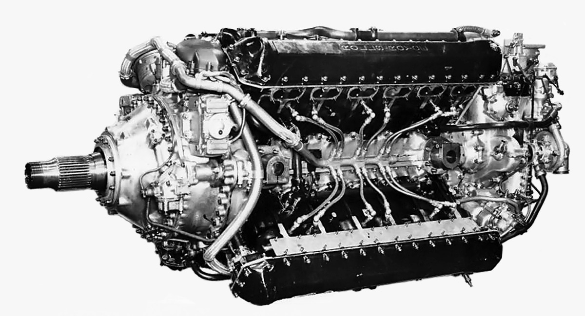
Rear view of the Vulture shows the coolant pumps flanking the supercharger. All of the cylinder banks were spaced at 90 degrees.
The Vulture’s connecting rod consisted of a master rod extending at a 45-degree angle from a square big end, with three articulating rods extending from the other corners of the big end. Initially, the connecting rod’s big end cap had a hinged joined on one side and was secured to the crankshaft with two bolts on the opposite side. Although different versions were tried, this configuration proved problematic and was replaced by omitting the hinge and using four bolts (two long bolts on one side and two short bolts on the other) to secure the cap to the connecting rod around the crankpin. The mating surfaces of the big end had corresponding serrations to ensure a secure fit. Incidentally, this was the same type of big end employed on the connecting rods of the Rolls-Royce Exe, the development of which had slightly proceeded that of the Vulture. When viewed from the rear of the engine, the upper right cylinder bank was designated as the ‘A’ bank, and the designations proceeded counterclockwise. The master rod served the ‘D’ bank, which was the lower right.
At the front of the engine, a spur gear on the crankshaft engaged four compound layshafts, the opposite side of which drove the propeller shaft. This compound gear reduction resulted in the propeller turning .350 times crankshaft speed and being mounted on the engine’s centerline. Viewed from the rear, the crankshaft and propeller both rotated counterclockwise. A bevel gear on the back side of each compound layshaft drove the vertical shaft for the respective cylinder bank’s camshaft. A spur gear on the rear of the crankshaft supplied power to various accessory drives and to the two-speed, single stage supercharger. The supercharger’s impeller turned at 5.464 and 7.286 times crankshaft speed in low and high gears. A coolant pump was mounted by each side of the supercharger. The engine’s compression ratio was 6.0 to 1.

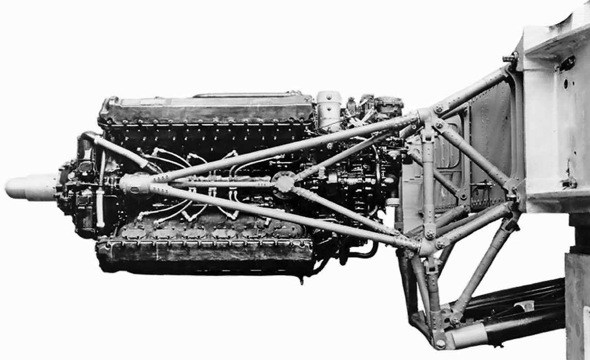
The mounting of the Vulture in the Manchester was similar to other installations—two pads on each side of the engine attached it to a tubular steel frame. The mounting pads were in the Vee formed by the upper and lower banks.
Air was drawn through the two-barrel SU carburetor and fed into the supercharger. The air/fuel mixture exited the supercharger via two outlets that respectively fed an upper or lower manifold. Each manifold was respectively positioned between the upper or lower cylinder banks. The manifold had three outlets on each side. The three outlets were connected to another manifold that was attached directly to and extended the length of the cylinder bank. The incoming charge for each cylinder was ignited by two spark plugs, one positioned in the intake side of the cylinder and the other on the exhaust side. This meant that access to the top, bottom, left, and right sides of the engine was needed to replace the spark plugs. The task was further complicated by the intake manifolds on the top and bottom and the exhaust manifolds and engine mounts on the left and right sides of the engine. Needless to say, the 24-cylinder Vulture was not a favorite with ground crews. The spark plugs were originally fired by a battery-powered coil ignition system, which was replaced by two magnetos and distributors driven from the gear reduction. The exhaust ports were on the left and right sides of the engine. A mixture of 70 percent water and 30 percent ethylene glycol was used to cool the engine.
The Vulture had a 5.00 in (127 mm) bore and a 5.50 in (140 mm) stroke. The engine’s total displacement was 2,591 cu in (42.47 L), and it had a takeoff rating of 1,800 hp (1,342 kW) at 3,200 rpm with 6 psi (.41 bar) of boost. At 3,000 rpm with 6 psi (.41 bar) of boost, the Vulture had a maximum rating of 1,845 hp (1,312 kW) at 5,000 ft (1,524 m) and 1,710 hp (1,223 kW) at 15,000 ft (4,572 m). At 2,850 rpm with 6 psi (.41 bar) of boost, the Vulture had an international rating of 1,780 hp (1,327 kW) at 4,000 ft (1,219 m) and 1,660 hp (1,237 kW) at 13,500 ft (4,115 m) and a maximum climb rating of 1,760 hp (1,312 kW) at 5,000 ft (1,524 m) and 1,640 hp (1,223 kW) at 15,000 ft (4,572 m). At 2,600 rpm with 5 psi (.34 bar) of boost, the engine had a maximum cruise rating of 1,540 hp (1,148 kW) in low gear and 1,460 hp (1,089 kW) in high gear. The Vulture was 87.2 in long, 35.8 in wide, and 42.3 in tall. The engine weighed 2,450 lb.

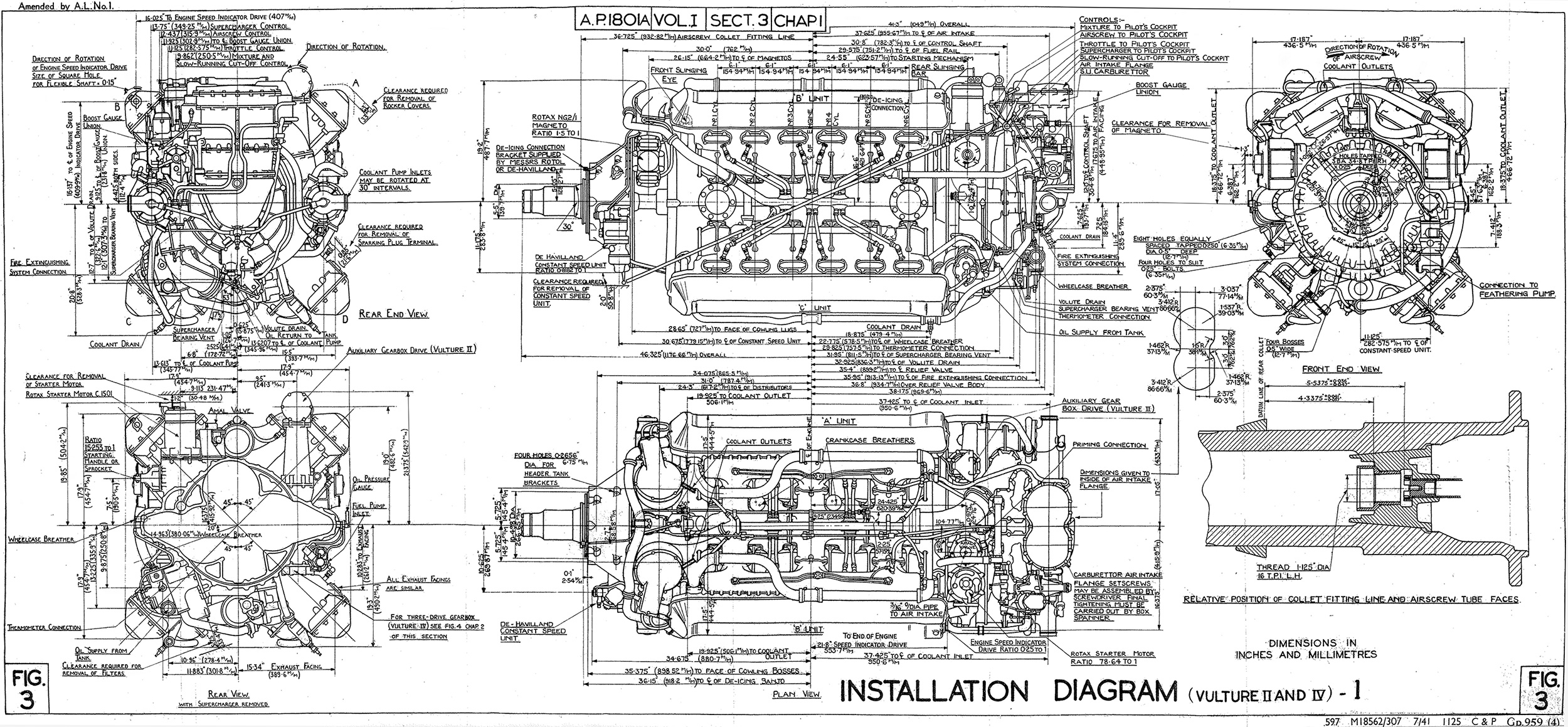
Installation Diagram for the Vulture II and IV engines. The main difference between the two variants was that the Vulture II drive an auxiliary gearbox via a right-angle drive mounted vertically behind the ‘A’ cylinder bank.
Preliminary testing of the Vulture engine included building an X-4 engine, and running this engine revealed the issues with the early two-bolt connecting rod design. Stresses on the bolts caused their failure, and the four-bolt connecting rod was developed. Another issue was insufficient lubrication of main bearings. The first complete 24-cylinder Vulture was run on 1 September 1937, the second in January 1938, and the third in May 1938. By November 1938, Vulture test engines had accumulated 1,150 hours of operation. Issues with the coil ignition system came to light while testing the complete engines, resulting in a switch to magnetos. In 1938, the Vulture produced 1,750 hp (1,305 kW) while on test.
Vulture engine development spanned from Mark I to Mark V. The Vulture I entered limited production and were mainly developmental engines. Refinements were incorporated into the Vulture II, which was intended for use in multi-engine aircraft. The Vulture II had a detached, five-drive, auxiliary gearbox that was driven from the engine by a flexible shaft. The flexible shaft connected to a right-angle drive mounted vertically behind the A (upper right when viewed from the rear) cylinder bank. The Vulture II was first run in September 1938. No descriptive information has been found regarding the Vulture III. The Vulture IV was nearly identical to the Vulture II but intended for single-engine aircraft. The Vulture IV had an engine-mounted three-drive auxiliary gearbox and different accessories.
The Air Ministry authorized engine production on 23 March 1939, anticipating a need for 1,560 Vultures, and true engine production started in January 1940. Issues with the Vulture necessitated a drop in its maximum speed to 3,000 rpm, but boost was increased to 9 psi (.62 bar) to maintain the engine’s takeoff rating of 1,800 hp (1,342 kW).

The Hawker Henley testbed (K5115) was the first aircraft to fly with a Vulture engine. The large scoop under the aircraft accommodated the coolant radiator and oil cooler.
Development of the Vulture V followed that of the Vulture IV and featured additional supercharging, with an impeller that turned at 6.018 and 8.111 times crankshaft speed in low and high gears. For takeoff, the engine had a rating of 1,995 hp (1,488 kW) at 3,000 rpm with 9 psi (.62 bar) of boost. Military power at the same rpm and boost was 2,035 hp (1,517 kW) at 5,000 ft (1,524 m) and 1,840 hp (1,372 kW) at 20,250 ft (6,172 m). At 2,650 rpm and with 7 psi (.48 bar) of boost, the Vulture V had a cruise rating of 1,650 hp (1,230 kW) at 3,500 ft (1,067 m) and 1,525 hp (1,137 kW) at 17,500 ft (5,334 m).
The Hawker Henley light-bomber prototype (K5115) was converted with a Vulture engine to serve as a testbed. A ventral scoop was added to the aircraft’s bomb bay that housed the radiator and oil cooler. The cowling was modified for the Vulture with its four rows of exhaust stacks, and a scoop for the carburetor was added just forward of the cockpit. The Vulture-powered Henley was first flown on 17 April 1939, and the Vulture passed a type-test with an 1,800 hp (1,342 kW) takeoff rating in August 1939. A second Henley (L3302) was converted to a Vulture testbed and made its first Vulture-powered flight on 3 May 1940. The Vulture engine was intended for a number of aircraft under development, four of which were flown.
The Avro 679 Manchester medium bomber used two Vulture I engines and was ordered in mid-1937, before the aircraft’s design was finalized. Eventually, orders for some 700 examples were placed. The Manchester prototype (L7246) made its first flight on 24 (some sources state 25) July 1939. When Vulture II engines became available, they were used in the Manchester, and the type entered service in November 1940.

A production Avro Manchester I (L7288) running up one of its Vulture engines. A shroud covered each exhaust manifold to help cool the exhaust so that the discharge did not heat the wing. The two-engine bomber was quite a handful when one of the Vultures failed, and a number of aircraft and their crew were lost due to engine issues.
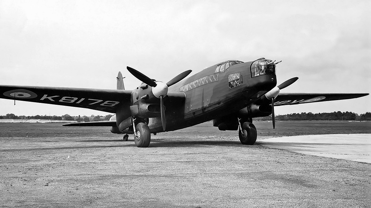
The Vickers Type 284 Warwick medium bomber was originally ordered in October 1935, but a change for the first prototype (K8178) to be powered by two Vulture I engines rather than the Bristol Hercules occurred in January 1937. K8178 made its first flight on 13 August 1939, and Vulture II engines were installed in November 1940.
Two prototypes of the Hawker Tornado fighter were ordered in December 1938. The first prototype (P5219) was powered by a Vulture II engine and made its first flight on 6 October 1939. Production contracts were issued in November 1939, with the Vulture V selected as the intended powerplant. The second prototype (P5224) used a Vulture V engine and made its first flight on 7 December 1940.
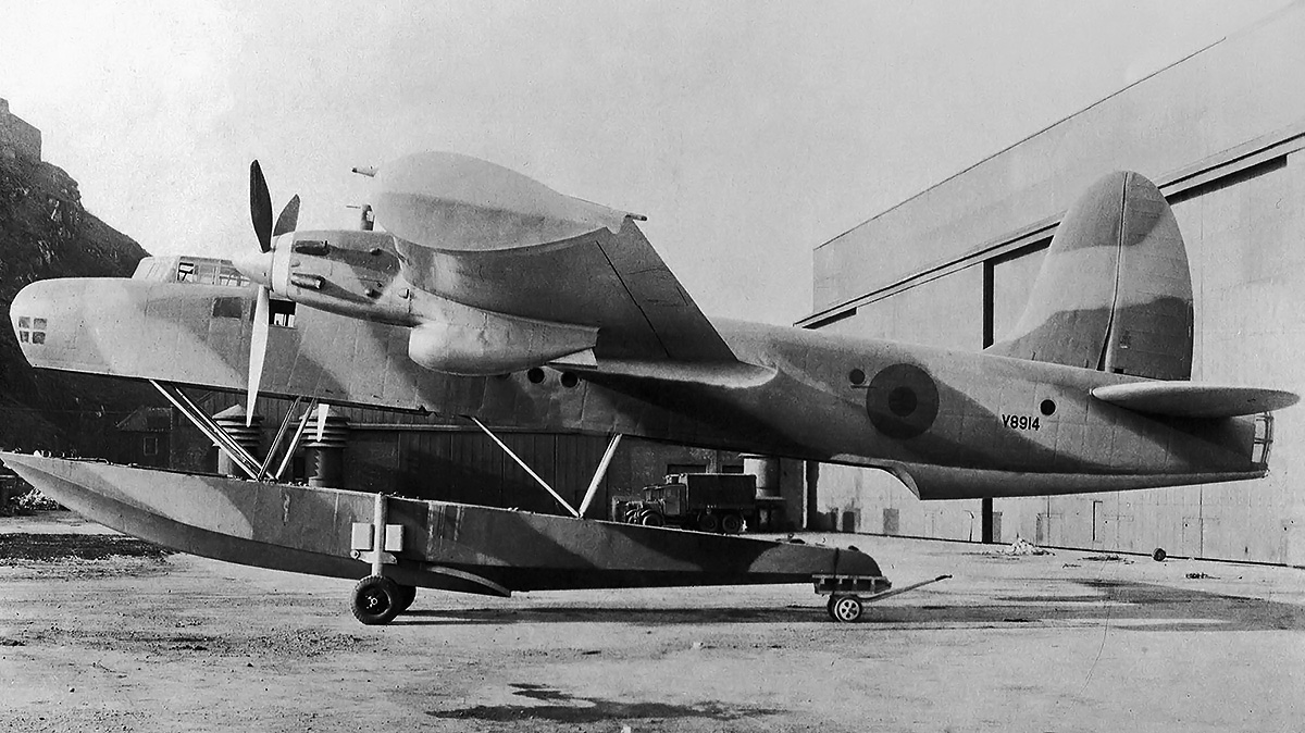
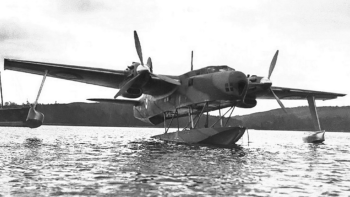
The Blackburn B-20 flying boat (V8914) was ordered in 1936 and made its first flight on 26 March 1940. The experimental aircraft was powered by two Vulture II engines and featured an extendable hull and retractable wing floats. The aircraft was lost on 7 April 1940 after aileron flutter was experienced during a high-speed test flight.
In March 1941 the improved Vulture II was type tested with a takeoff rating of 2,010 hp (1,499 kW) at 3,000 rpm with 9 psi (.62 bar) of boost. At the same rpm and boost, the engine’s military power rating was 1,845 hp (1,376 kW) at 5,000 ft (1,524 m) and 1,710 hp (1,275 kW) at 15,000 ft (4,572 m). At 2,850 rpm and with 6 psi (.41 bar) of boost, the Vulture II had a normal rating of 1,780 hp (1,327 kW) at 4,000 ft (1,219 m) and 1,660 hp (1,238 kW) at 13,500 ft (4,115 m). However, the Vultures in service were taking a turn for the worse.

The Vickers Warwick prototype (K8178) was the only example of the type fitted with Vulture engines.
The Manchester’s rush into production and subsequent rush into service meant that a number of deficiencies with the airframe and serious issues with the Vulture engine were not discovered until it was too late. The engines proved to be unreliable and prone to failure. As a result, all Manchesters were grounded numerous times. Manchesters with a failed Vulture were often unable to maintain height on one engine, and about 75 percent of the time, the aircraft crashed before an emergency landing could be executed at a suitable location. A contributing factor to the Vulture’s issues was that the Battle of Britain forced Rolls-Royce to focus on the Merlin engine, which delayed Vulture development.
Some engine failures were attributed to cooling issues. One of the coolant pumps would cavitate, halting the flow of coolant to that side of the engine. The affected cylinder banks would subsequently overheat, and the engine would seize; an engine fire resulted on a number of occasions. To fix the issue, a balance tube was installed which connected the inlet of the pumps to equalize pressure between the two. The crankshaft main bearings were also prone to failure. Numerous issues resulted in the failed bearings: over-heating due to the already mentioned coolant issues, poor lubrication, ineffective bearing material, and a slight misalignment of the two crankcase halves. The Vulture’s lubrication system was reworked to prevent aeration, and a new LA4-type bearing material was adopted. The misalignment issue was solved by including locating dowels through which cross bolts passed. A dowel was positioned on each side of the main bearings between the crankcase halves. The most vexing issue was the random failure of bolts securing the connecting rod cap. This typically created cascading failures that resulted in the sudden and catastrophic loss of the engine. The issue was traced to brittle bolts, and new measures were implemented to ensure they were tightened to the new, lower toque standard to prevent excessive strain and stretching. The connecting rod was also modified slightly. In addition, the Vulture’s maximum speed was reduced again to 2,850 rpm to minimize the risk of failure. The last of these changes were detailed by Rolls-Royce under Vulture Modification No. 44. By August 1941, engines with these changes were installed in some Manchesters, and the Vulture began to reliably make it 120-hours between major inspections. In addition, Manchesters were now able to make it to an airfield on a single engine more often than not. Eventually, the time between inspections was raised to 180 hours, and the engine’s maximum takeoff speed was increased to 3,000 rpm. However, another issue with Vulture engines came to light in late 1941. Exhaust manifolds were cracking and failing, resulting in a jet of hot gasses flowing against the engine, cowling, or other internal components. The failed manifolds caused engine failures or airframe damage or both. A new manifold was designed, and all of the older units were replaced in December 1941.

The second Hawker Tornado prototype (P5224) with its Vulture V engine. The Vulture was relatively well-behaved during testing of the Tornado, which was very similar to the Sabre-powered Typhoon.
Even though the main problems with the Vulture were mostly resolved, engines continued to encounter various random issues, including failures, overheating, lack of power, and excessive fuel consumption. Overall, there was little faith in the Vulture engine. The Manchester itself continued to have issues, and production was halted in November 1941. Of the 202 aircraft built, approximately 33 (16.3 percent) crashed or were struck off charge due to engine failures or fires. This number does not include aircraft that were repaired after an engine failure, nor does it include the six or so aircraft lost due to propeller issues (some of which precipitated an engine failure). Tragically, also not included are the numerous Manchesters that crashed after one engine was knocked out from battle damaged only to have the “good’ engine fail after it was overstressed trying to keep the underpowered aircraft aloft. The Manchester was withdrawn from operations in mid-1942 and served in various secondary roles through 1943, when all examples were scrapped.
The Manchester was redesign to use four Merlin engines and became the Lancaster (originally Manchester III), one of the greatest World War II bombers. Production Warwicks were fitted with either Pratt & Whitney R-2800 or Bristol Centaurus engines. While around 1,760 Tornados were ordered at one point, only three Vulture-powered examples were built, and the Napier Sabre-powered Typhoon took over in place of the Tornado.

The Blackburn B-20 was an experimental aircraft which tested a retractable hull to improve the aerodynamics of flying boats. With a top speed of over 300 mph (483 km/h), the B-20 showed potential, but it was lost during an early test flight.
By September 1942, a Vulture engine with a contra-rotating gear reduction was installed in the sole-production Tornado (R7936). The engine and aircraft were used to test Rotol and de Havilland contra-rotating propellers. Some sources report that one Vulture engine was built with its bore increased by .4 in (10 mm) to 5.4 in (137 mm), the same as the Merlin. This increased the engine’s displacement by 432 cu in (7.08 L) to 3,023 cu in (49.54 L). However, no further information on these engines has been found.
From as early as August 1939, Rolls-Royce wanted to cancel Vulture development so that the company could focus its resources on other engines, mainly the Merlin and Griffon. However, the Air Ministry felt that it needed the Vulture engine, so development continued. Vulture development was halted in October 1941, and production ended in March 1942, with 538 engines built. The Vulture was the only X-24 aircraft engine to enter production.
Rolls-Royce had designed a number of changes to be incorporated into the Vulture engine if production had continued. The connecting rod was redesigned with the three articulated rods attached to the bearing cap, and the cap was secured to the master connecting rod via four long bolts made from improved material. The cylinder banks were redesigned to incorporate a detachable cylinder head. A lighter planetary gear reduction for the propeller would have replaced the four compound layshafts. The two-speed supercharger was redesigned to include two-stage supercharging to improve the engine’s performance at higher altitudes.

The sole-production Tornado (R7936) seen in 1943 with a Vulture engine turning de Havilland contra-rotating propellers. The aircraft was also used to test Rotol contra-rotating propellers.
Only a small number of Vulture engines survive, and most were recovered from Manchester wrecks. Two recovered Manchester engines (engine 1 and engine 2) are held by the Luchtoorlogmuseum (Aerial Warfare Museum) Fort Veldhuis in Heemskerk, near Amsterdam in the Netherlands. A Vulture engine from the B-20, consisting mainly of the crankshaft, connecting rods, and cylinder barrels, is displayed in the Dumfries and Galloway Aviation Museum in Scotland. Three engines are part of the Royal Air Force Museum’s collection, and all are believed to have been recovered from Manchester wrecks. One of these engines is on loan to the Rolls-Royce Heritage Trust and is displayed at the Hucknall Flight Test Museum.
Note: Many sources state that the Vulture I used an updraft carburetor, and the Vulture II and later variants used a downdraft carburetor. However, the only aircraft that appears to have had an updraft carburetor was the first Tornado prototype, which reportedly flew with a Vulture II. Early Manchesters that reportedly flew with Vulture Is appear to have downdraft carburetors. In my opinion, the most logical explanation, although still questionable, is that all Vultures had downdraft carburetors and that the early installation in the Tornado prototype that incorporated the carburetor inlet with the belly scoop was an attempt to maximize the pilot’s forward vision and minimize the number of external protuberances.

The shattered remains of a Vulture II engine from Manchester R5779 shot down on 9 March 1942 near Oranje, Netherlands. The engine is actually on its side, and the view is of the induction manifold on the bottom of the engine. Note the severe deformation of the cylinder bank. The engine is displayed at the Luchtoorlogmuseum (Aerial Warfare Museum) Fort Veldhuis in Heemskerk. (Fort Veldhuis Airwarmuseum image)
Sources:
– Major Piston Engines of World War II by Victor Bingham (1998)
– The Avro Manchester: The Legend Behind the Lancaster by Robert Kirby (2015)
– Rolls-Royce Piston Aero Engines – a designer remembers RRHT 16 by A. A. Rubbra (1990)
– Rolls-Royce Vulture II and IV Description: Air Publication 1801A Volume I, via the Aircraft Engine Historical Society (December 1940)
– Rolls-Royce Aero Engines by Bill Gunston (1989)
– Aircraft Engines of the World 1945 by Paul H. Wilkinson (1945)
– Hawker Aircraft since 1920 by Francis K. Mason (1991)
– Avro Aircraft since 1908 by A. J. Jackson (1990)
– Vickers Aircraft since 1908 by C. F. Andrews and E. B. Morgan (1988)
– Blackburn Aircraft since 1909 by A. J. Jackson (1989)
– https://www.key.aero/forum/historic-aviation/62280-rolls-royce-vulture-survivors