Hispano-Suiza 24Z left

Hispano-Suiza 24Z (Type 95) Aircraft Engine

By William Pearce

Starting around 1938, Hispano-Suiza began to halt development of its other aircraft engines to focus on its latest V-12, the 12Z (Type 89). The 12Z drew heavily from the Hispano-Suiza 12Y but had many improvements, including two-speed supercharging and four-valves per cylinder actuated by dual-overhead camshafts. France was in desperate need of high-powered aircraft engines to keep its air force comparable to those of other European nations during the build-up to World War II. The 12Z was developing 1,400 hp (1,044 kW) at 2,600 rpm when France surrendered in June 1940.

Hispano-Suiza 24Z right

The Hispano-Suiza 24Z incorporated the improved features of the 12Z engine but was very similar to the 24Y. Note the high position of the propeller shafts to accommodate a cannon mounted between the upper cylinder banks and firing through the propeller hub. The magnetos for the right side of the engine can be seen mounted to the propeller gear reduction housing.

One of the engine programs that was suspended because of the 12Z was the Hispano-Suiza 24Y: a 2,200 hp (1,641 kW), 24-cylinder H engine utilizing many 12Y components. Not long into the 12Z program, engineers started to wonder what level of performance could be achieved by a 24-cylinder engine using 12Z components. In 1943 and under German occupation, development began on the Hispano-Suiza 24Z (Type 95) engine.

The 24Z had the same vertical H-24 configuration as the earlier 24Y with two cylinder banks situated above crankcase and another two cylinder banks below. The two-piece crankcase was made from aluminum and split horizontally. A crankshaft served each upper and lower cylinder bank pair. Each one-piece crankshaft had six-throws, was counterbalanced, and was supported by seven main bearings. The pistons were connected to the crankshafts via fork-and-blade connecting rods. The crankshafts, connecting rods, and pistons were the same as those used in the 12Z engine.

Each of the 24Z’s four cylinder banks was made up of a six-cylinder block with an integral crossflow cylinder head. The two intake valves and two exhaust valves for each cylinder were controlled by separate overhead camshafts. The camshafts were driven from a vertical shaft at the rear of each cylinder bank. The cylinder banks and their valve train were from the 12Z engine.

Hispano-Suiza 24Z left

Each left and right half of the 3,600 hp (2,685 kW) 24Z engine could operate independently of the other half. Note the intake manifolds routing air from the supercharger to the cylinder banks and the drive shaft for the fuel injection pump extending from the rear of the engine.

Two superchargers were mounted at the rear of the engine with their impellers parallel to the engine’s crankshafts. Originally, single-speed supercharges were used, but these were later replaced with two-speed units. At low speed, the supercharger’s impeller spun at 6.72 times crankshaft speed. At high speed, the impeller spun at 9.52 times crankshaft speed. Supercharger speed change and boost control were automatic. Separate intake manifolds led from each supercharger to the inner side of the upper and lower cylinder banks. Mounted on each side of the crankcase was a fuel pump that injected fuel directly into each cylinder. Each fuel pump was driven via a shaft from the rear of the engine. The two spark plugs per cylinder were positioned below the intake valves. The spark plugs for each upper and lower cylinder bank pair were fired by two magnetos mounted to the propeller gear reduction case.

The front of each crankshaft engaged a separate propeller shaft at a .44 to 1 gear reduction. The two propeller shafts made up a contra-rotating unit. The 24Z was not built with a single-rotation propeller shaft. The engine had provisions for a cannon to be mounted between the upper cylinder banks and fire through the hollow propeller shaft. Each upper and lower cylinder bank pair on the 24Z constituted a 12-cylinder engine section, and each engine section could operate independently of the other.

Sud-Est 580 HS 24Z

The Sud-Est SE 580 under construction with the 24Z engine installed. Note the supercharger intake on both sides of the cowling. Also note the upper and lower row of exhaust stacks. The scoop behind the cockpit was for the radiators.

The Hispano-Suiza 24Z had a 5.91 in (150 mm) bore and a 6.69 in (170 mm) stroke. The engine’s total displacement was 4,400 cu in (72.10 L). The 24Z produced 3,600 hp (2,685 kW) at 2,800 rpm for takeoff. This power was achieved at an over-boosted condition of 7.7 psi (.53 bar); normal boost was 7.0 psi (.49 bar). Max power with low-speed supercharging was 3,200 hp (2,386 kW) at 2,800 rpm at 8,202 ft (2,500 m). Max power with high-speed supercharging was 2,640 hp (1,969 kW) at 2,800 rpm at 26,247 ft (8,000 m). The engine’s normal rating was 3,000 hp (2,237 kW) at 2,600 rpm at 8,202 ft (2,500 m) with low-speed supercharging and 24,606 ft (7,500 m) with high-speed supercharging. The 24Z’s cruising power was 1,500 hp (1,119 kW) at 2,100 rpm at 9,843 ft (3,000 m) with low-speed supercharging and 18,373 ft (5,600 m) with high-speed supercharging. The engine had a specific fuel consumption of .48 lb/hp/hr (292 g/kW/hr). The 24Z was 10.72 ft (3.27 m) long, 4.27 ft (1.30 m) wide, 4.54 ft (1.39 m) tall, and weighed 3,197 lb (1,450 kg).

World War II hindered the 24Z’s construction. The engine was first run in 1946, and it was exhibited at the Salon de l’Aéronautique (Air Show) in Paris in November 1946. Bench tests of the 24Z revealed some serious issues, the extent of which have not been found. In September 1947, the engine’s compression was lowered to 6.75 to 1 from its original value of 7.0 to 1. Perhaps this change was an attempt to cure issues with detonation. Later, the gear reduction failed while a 24Z was under test, destroying the engine.

The 24Z’s prime application was the Sud-Est* SE 580/582 fighter that was designed during the war. However, issues with the 24Z resulted in the substitution of an Arsenal 24H engine for the SE 580. The SE 580 itself was later scrapped before the aircraft was completed. Many other projects, mostly flying boats and transports, were proposed with 24Zs as their power plant. None of these projects made it off the drawing board.

Hispano-Suiza 48Z Late 133

Drawing of two Hispano-Suiza 48Z engines installed in the wing of a Latécorère 133 flying boat. (image relabeled, but originally from “Latécorère: Les avions et hydravions” by Jean Cuny)

A further Hispano-Suiza proposal consisted of coupling two 24Z engines together to create the 48Z (Type 96) engine. In this configuration, the propeller shaft of the rear 24Z engine section passed between the upper cylinder banks of the front 24Z engine section and extend though the propeller shaft of the front engine. The rear 24Z powered the front propeller of a coaxial contra-rotating unit, while the front 24Z powered the rear propeller. The 48Z would have used four turbosuperchargers—two mounted near the front of the engine and two mounted at the rear. The 48-cylinder 48Z engine displaced 8,800 cu in (144.20 L), had a takeoff rating of 7,200 hp (5,369 kW) at 2,800 rpm, and produced 5,200 hp (3,878 kW) at 13,123 ft (4,000 m). Like many large engine projects at the dawn of the jet age, the 48Z existed only on paper.

With the 24Z’s developmental issues and no tangible prospects for installation in an aircraft, the engine program was stopped in 1948. At least two 24Z engines were built, but probably not many more. One engine survives and is preserved in the Musée de l’Air et de l’Espace in le Bourget (near Paris), France.

Hispano-Suiza 24Z

The Hispano-Suiza 24Z preserved in the Musée de l’Air et de l’Espace in le Bourget, France. Most likely, this is the engine that was displayed at the 1946 Salon de l’Aéronautique and was installed in the SE 580. (image via Le Rêve d’Icare)

*The SE 580/582’s development began at what was Dewoitine, which had been nationalized into SNCAM (Société nationale des constructions aéronautiques du Midi or National Society of Aircraft Constructors South). SNCAM was absorbed into SNCASE (Société nationale des constructions aéronautiques du Sud-Est or National Society of Aircraft Constructors Southeast), which is often shortened to just Sud-Est.

Sources:
Hispano Suiza in Aeronautics by Manuel Lage (2004)
Jane’s All the World’s Aircraft 1947 by Leonard Bridgman (1947)
Aircraft Engines of the World 1947 by Paul H. Wilkinson (1947)
Latécorère: Les avions et hydravions by Jean Cuny (1992)
– “Engines at the Paris Show” Flight (21 November 1946)

1939 Venturi-Mora Saimon-Fiat

Idroscivolanti and the Raid Pavia-Venezia

By William Pearce

An airboat is a vessel that has a shallow draft and utilizes the thrust generated by an aircraft propeller to drive over ice, grass, or water. The airboat concept started as a way to test propellers but evolved into a nearly indispensable form of transportation though swampy areas. In Italy in the 1930s, the concept of an airboat was taken a bit further.

1930 Mazzotti-Cattaneo SIAI-IF

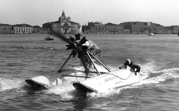
The Isotta Fraschini Asso 200-powered SIAI hydroplane that Franco Mazzotti and Guido Cattaneo drove to victory in the 1930 and 1931 Raid Pavia-Venezia.

First run in 1929, the Raid Pavia-Venezia was an inshore powerboat race of around 269 miles (433 km) held in June. The course distance varied slightly by year. Starting on the Ticino River in Pavia, Italy, the race transitioned to the River Po and then through canals, finally ending in Venice. Fuel stops were incorporated along the route. Various parts of the course had many turns, hidden sandbars, and tight passageways. The Raid Pavia-Venezia was the creation of Vincenzo Balsamo, an engineer, sailor, and head of the Gruppo Motonautico della Lega Navale di Milano (Powerboat Section of the Navy League of Milan), the group that organized the race. The 1929 race was completed in 11:26:23 at an average of 22.164 mph (35.670 km/h).

1932 Biseo-Bertoli SIAI-FIAT

Attilio Biseo and Gino Bertoli won the 1932 Raid Pavia-Venezia in this SIAI idroscivolante powered by a FIAT A50 engine. (image via Three Point Hydroplanes)

The 1930 race marked the start of combining powerful Italian aircraft engines with shallow-hulled hydroplanes to create the idroscivolante (airboat). Idroscivolanti (airboats) would not only increase straight line speeds, they would also allow the boats to travel over shallow sandbars without worry. Only one idroscivolante was entered in the 1930 race. It used an Isotta Fraschini (IF) Asso 200 engine that turned a four-blade, wooden propeller. The Asso 200 was a 200 hp (149 kW), water-cooled, inline-six engine. It was mounted in a pusher configuration to the rear of a shallow-hulled boat built by SIAI (Società Idrovolanti Alta Italia or Northern Italy Seaplane Company, also known as Savoia-Marchetti). Driven by Count Franco Mazzotti with co-driver Guido Cattaneo, the SIAI/IF idroscivolante won the race with a time of 8:10:35, averaging 31.462 mph (50.633 km/h). The second place finisher was nearly an hour behind the idroscivolante.

1934 Salom-Celli Celli-SPA

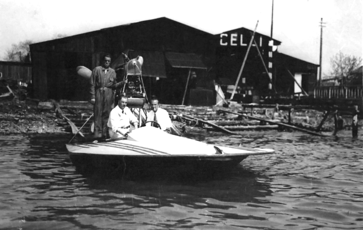
The Celli hydroplane powered by an SPA 6A engine in a pusher configuration. Aldo Salom and Dino Celli campaigned this boat in 1933 and 1934. (image via Three Point Hydroplanes)

Mazzotti and Cattaneo won the 1931 race again in the SIAI/IF idroscivolante with a time of 6:52:54 and averaging 38.309 mph (61.653 km/h). However, they had competition in the form of driver Count Theo Rossi and co-driver Alfredo Stracconi in a Passarin idroscivolante powered by a FIAT (Fabbrica Italiana Automobili Torino or Italian Automobile Factory Turin) A50 engine. The A50 was an air-cooled, seven-cylinder, radial engine that produced 105 hp (78 kW). Rossi and Stracconi finished the race in second place at 33.648 mph (54.151 km/h).

Rossi and Stracconi were back in their Passarin/FIAT in 1932, but they were unable to complete the race. The only other idroscivolante was a SIAI powered by a FIAT and driven by Attilio Biseo and Gino Bertoli. The FIAT A50 radial engine was mounted in a tractor configuration on struts in the middle of the boat. Biseo and Bertoli won the 1932 race in 5:27:26 at a 47.138 mph (75.862 km/h) average speed. Biseo and Bertoli finished the Raid Pavia-Venezia 2:30:01 before the first conventional powerboat.

1934 Rossi-Cattaneo SIAI-IF

Theo Rossi and Guido Cattaneo paired up to compete in the Raid Pavia-Veneziain in this SIAI idroscivolante powered by an IF Asso 200 engine. This photo was most likely taken in 1934. (image via Three Point Hydroplanes)

For 1933, Theo Rossi and Guido Cattaneo joined forces in the SIAI/IF. The SIAI/FIAT idroscivolante was entered by driver Marcello Visconti di Modrone and co-driver Franco Mazzotti, but it did not finish the race. Rossi and Cattaneo took the win with a time of 6:37:14, averaging 40.639 mph (65.402 km/h) over the whole course. The pair averaged 56.511 mph (90.946 km/h) over the 37 miles (60 km) between Piacenza and Cremona.

In 1934, two of the three idroscivolanti entered in the race failed to finish. One of the non-finishers was a new, small SIAI hydroplane raced by Rossi and Cattaneo. It was powered by a 200 hp (149 kW) IF Asso 200 inline-six engine in a tractor configuration and housed in a streamlined cowling; the engine and propeller were probably from the previous SIAI/IF boat. The other idroscivolante that did not finish was a Celli hydroplane powered by a SPA (Società Ligure Piemontese Automobili or Ligure Piemontese Automobile Company) 6A engine and raced by Aldo Salom and Dino Celli. Their 205 hp (153 kW) inline-six engine was mounted at the rear of the boat in a pusher configuration and turned a four-blade, wooden propeller. The race was won by driver Attilio Biseo with co-driver Renato Donati in a SIAI hydroplane powered by a Farina T.58 135 hp (101 kW), air-cooled, five-cylinder, radial engine. The engine turned a two-blade propeller and was mounted in a tractor position at the middle of the boat. Their time was 5:44:08 with an average of 47.188 mph (75.942 km/h).

1934 Biseo-Donati SIAI-Farina

Attilio Biseo and Renato Donati competing in the 1934 race, which they won. Their SIAI idroscivolante was powered by a Farina T.58 engine. (image via Three Point Hydroplanes)

Four idroscivolanti competed in the 1935 Raid Pavia-Venezia. Driver Renato Donati and co-driver Federico Borromeo finished in sixth place overall. Their sleek, two-hulled, catamaran idroscivolante was designed by the Laboratorio Sperimentale Regia Aeronautica (Royal Italian Air Force Experimental Laboratory) but was most likely built by SIAI. It was powered by an air-cooled, seven-cylinder, 200 hp (149 kW) Alfa Romeo Lynx radial engine based on the Armstrong Siddeley Lynx and produced under license. The engine turned a three-blade, metal propeller and was mounted in a tractor configuration in the middle of the idroscivolante. In fourth place overall were Aldo Salom and Dino Celli in the Celli/SPA. In second place were driver Goffredo Gorini and co-driver Francesco Bertoli in the sister ship of Donati and Borromeo. However, their idroscivolante did not have a deck connecting the two hulls. Gorini and Bertoli finished the race in 5:12:30 and averaged 51.652 mph (83.126 km/h). The winners of the 1935 race were Rossi and Cattaneo in the SIAI/IF. Their boat had been modified with larger fuel tanks that bulged out above the two-hulls. Rossi and Cattaneo completed the race in 5:01:50 at 53.483 mph (86.073 km/h). They averaged 69.326 mph (111.570 km/h) over the 37 miles (60 km) from Piacenza to Cremona.

1935 Donati-Borromeo LSAR-AR

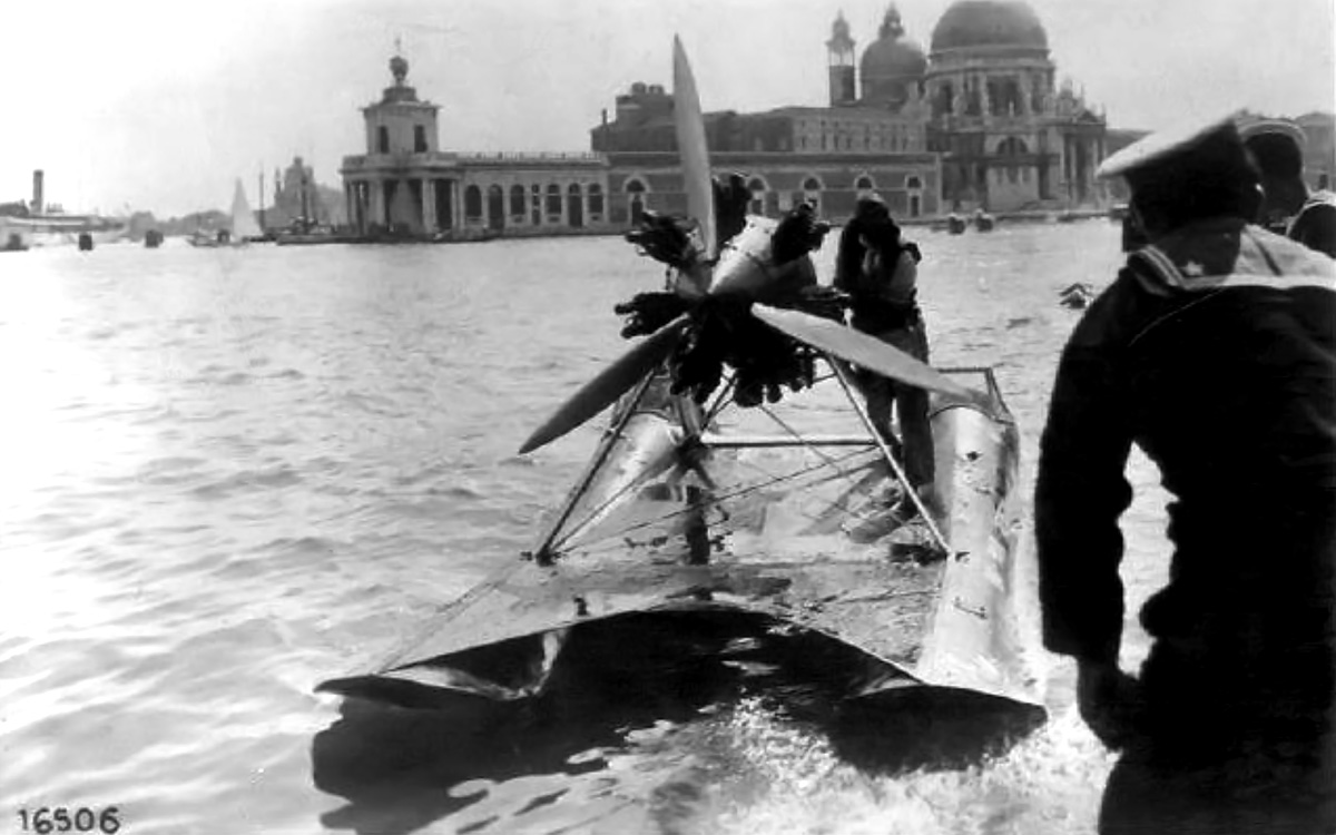
Renato Donati and Federico Borromeo in the Laboratorio Sperimentale Regia Aeronautica powered by an Alfa Romeo Lynx in 1935. Note the deck connecting the hulls. The idroscivolante sits in Venice’s Grand Canal with the Santa Maria della Salute in the background. (image via Three Point Hydroplanes)

Theo Rossi and Guido Cattaneo took another win in their SIAI/IF for 1936. Their time was 4:45:02 at an average speed of 56.576 mph (91.051 km/h), and they finished over three hours before the first conventional powerboat. Second place was won by Vito Mussolini and Carlo Maurizio Ruspoli in the SIAI/Farina. Vito Mussolini was Benito Mussolini’s nephew, and Carlo Maurizio Ruspoli was a Prince of Poggio Suasa. The third and last idroscivolante entered in the 1936 race was the Laboratorio Sperimentale Regia Aeronautica/Alfa Romeo of Goffredo Gorini and Renato Donati. While they did not finish the race, they did average 74.191 mph (119.400 km/h) over the 43 miles (69 km) between Pavia and Piacenz.

A race was also run on the Danube River between Vienna and Budapest in 1936. Which idroscivolanti participated and the results of the race have not been found. It can be assumed that the SIAI/IF idroscivolante raced by Rossi and Cattaneo did participate in this race, as it had “Vienna-Budapest” painted on its hull during the Pavia-Venezia race. At around 177 miles (285 km), the Vienna-Budapest race was about two-thirds the distance of the Raid Pavia-Venezia.

1935 Gorini-Bertoli LSAR-AR

The other Laboratorio Sperimentale Regia Aeronautica/Alfa Romeo driven by Goffredo Gorini and Francesco Bertoli in the 1935 Raid Pavia-Venezia. (image via Three Point Hydroplanes)

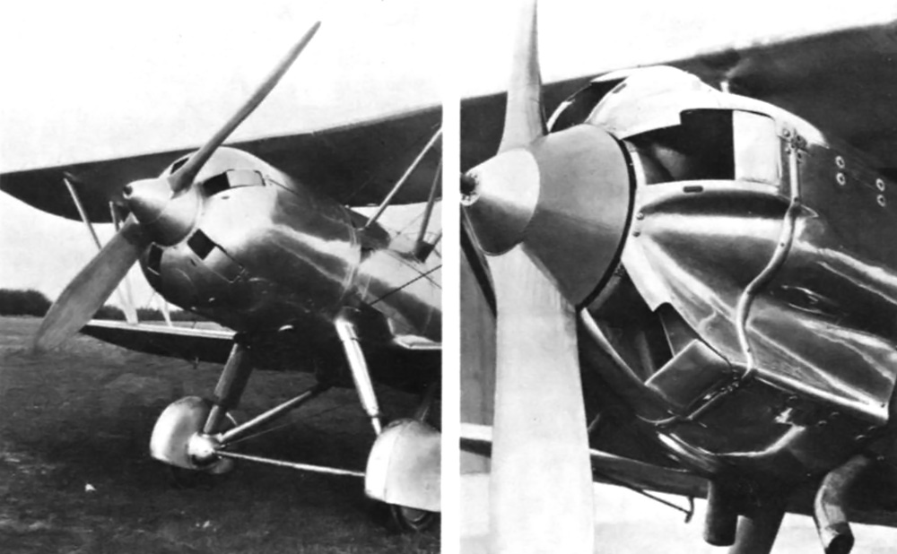
In 1937, driver Goffredo Gorini and co-driver Renato Donati won the race. Their idroscivolante was referred to as an SIAI, replacing Laboratorio Sperimentale Regia Aeronautica. The boat was still powered by an Alfa Romeo Lynx, but the engine struts and supports had been redesigned. In addition, a wide cord, two-blade, metal propeller was used. Gorini and Donati’s winning time was 4:47:32 with an average speed of 56.143 mph (90.354 km/h). In the sister ship, Prospero Freri and Salvatore Flamini took second place just 10 minutes behind the leader, with an average speed of 54.175 mph (87.186 km/h). Their idroscivolante was referred to as a CNA (Compagnia Nazionale Aeronautica or National Aeronautical Company), replacing Laboratorio Sperimentale Regia Aeronautica. The catamaran had new engine struts that now supported a nine-cylinder, 240 hp (179 kW) Alfa Romeo D.2 engine turning a three-blade, metal propeller. A Townend ring intended to reduce drag and improve engine cooling encircled the D.2’s cylinders. Theo Rossi and Guido Cattaneo, the previous year’s winners, placed third in their SIAI/IF.

1936 Rossi-Cattaneo SIAI-IF

Theo Rossi and Guido Cattaneo won the 1936 race in the SIAI/IF idroscivolante. Note the increased capacity fuel tanks that bulged above the deck and that “Budapest” is written on the hull. (image via Three Point Hydroplanes)

1938 saw five idroscivolanti entered in the Raid Pavia-Venezia race. Goffredo Gorini and Marco Ponzalino won the race in a SIAI/Alfa Romeo at a very fast time of 4:11:28, averaging 64.193 mph (103.308 km/h). Prospero Freri and Salvatore Flamini in the CNA/Alfa Romeo finished in second place. Vito Mussolini and Luciano Agosti took third place in the SIAI/Farina. Marco Celli and Aldo Tassinari finished in eighth place overall in a Celli catamaran powered by a 115 hp (86 kW) Walter Venus engine. On this boat, the seven-cylinder radial engine turned a three-blade propeller and was strut-mounted in a tractor configuration on the rear half of the catamaran. The last idroscivolante finished in ninth place overall; it was Aldo Salom and Bruno Rocca in a Celli hydroplane powered by an IF Asso 200 inline-six engine. The engine turned a four-blade, wooden propeller and was rear-mounted in a pusher configuration. Theo Rossi and Guido Cattaneo did not finish in their SIAI/IF.

1936 Mussolini Ruspoli SIAI-Farina

Vito Mussolini and Carlo Maurizio Ruspoli competing in the 1936 Raid Pavia-Venezia in the SIAI/Farina idroscivolante. (image via Three Point Hydroplanes)

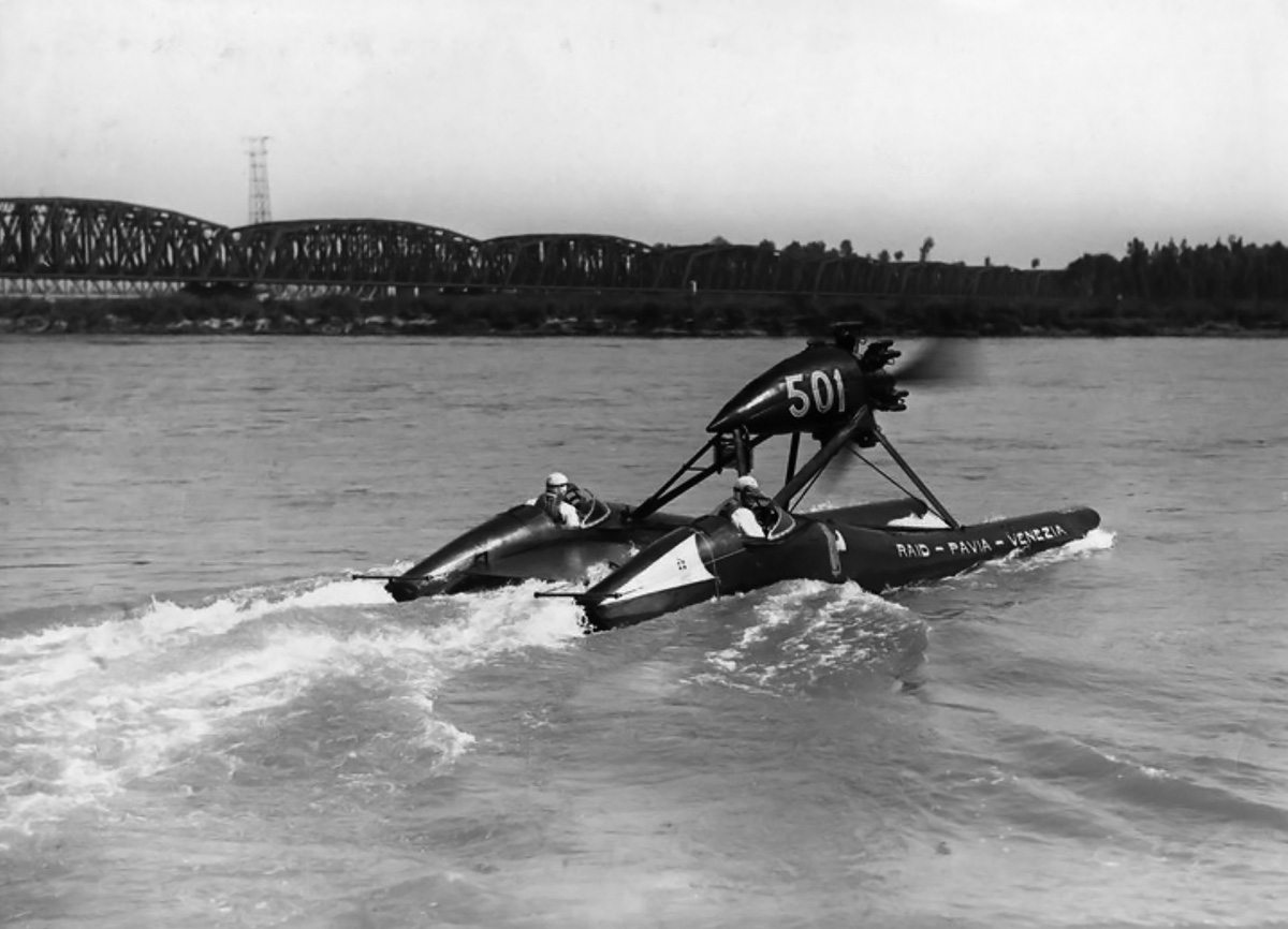
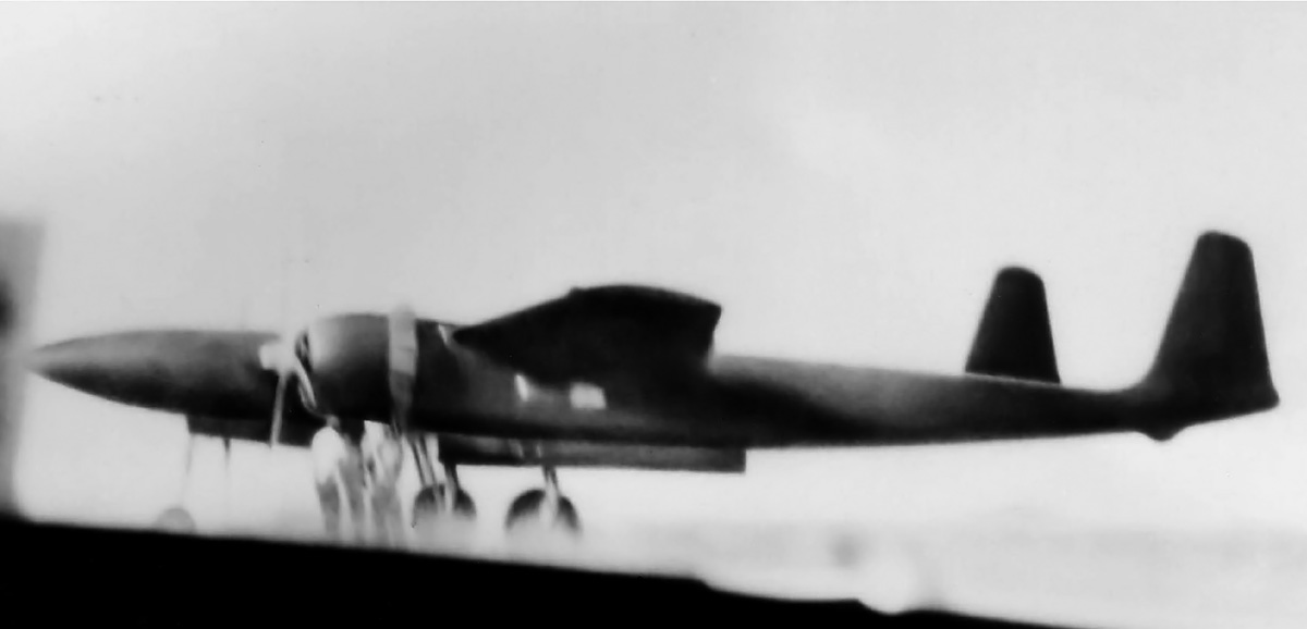
In 1939, Goffredo Gorini and Marco Ponzalino won the Raid Pavia-Venezia again at a slightly slower pace than the previous year. They finished in 4:19:16 at an average speed of 62.264 mph (100.205 km/h). The pair averaged 79.477 mph (127.80 km/h) over the 43 miles (69 km) from Pavia to Piacenz and finished the race 3:32:44 before the first conventional powerboat. Sources list their idroscivolante as a Gorini powered by an Alfa Romeo engine. However, film taken during a speed run in August shows a catamaran very similar to the one used the previous year but powered by a Wright R-975 Whirlwind 330 hp (246 kW), nine-cylinder, radial engine that turned a two-blade, metal propeller. Finishing twenty-three minutes behind them was their sister ship, listed as a Gorini/Freri/Alfa Romeo. Driver Prospero Freri and co-driver Salvatore Flamini averaged 57.148 mph (91.970 km/h). Freri and Flamini’s idroscivolante no longer had a Townend ring around the engine; the Alfa Romeo D.2’s cylinders were exposed to the air. In addition, a two-blade, metal propeller was installed. Fernando Venturi and Paolo Mora finished third in a Saliman (some sources say Saimon) catamaran powered by a FIAT A50 engine. The engine of this two-hulled idroscivolante was mounted in a tractor configuration at the center of the boat and turned a two-blade, wooden propeller. The SIAI/Farina idroscivolante of Vito Mussolini and Luciano Agosti finished in fourth place.

1937 Gorini-Donati LSAR-AR

Goffredo Gorini and Renato Donati won the 1937 race in the SIAI/Alfa Romeo idroscivolante. Note the wide cord, two-blade propeller on the Lynx engine.

In July 1939, Fernando Venturi in the Saliman/FIAT idroscivolante set an 800 kg (1,764 lb) class speed record of 49.692 mph (79.971 km/h) on Lake Bracciano. The record was broken in August when Goffredo Gorini achieved 91 mph (147 km/h) in the Wright Whirlwind-powered Gorini idroscivolante mentioned earlier. This appears to be a new idroscivolante, as the Alfa Romeo Lynx-powered machine was also present for the speed runs. Gorini had reached 96 mph (155 km/h), but technical difficulties prevented him from maintaining that speed. Gorini’s Wright-powered idroscivolante still had “Raid-Pavia-Venezia” painted on the hull from the race two months earlier.

1938 Freri-Flamini CNA-AR

For the 1937 Raid Pavia-Venezia, Prospero Freri and Salvatore Flamini installed a nine-cylinder Alfa Romeo D.2 engine with a three-blade propeller and a Townend ring. The pair took second place in 1937, 1938, and 1939. This photo is from the 1938 race.

The Raid Pavia-Venezia was suspended in 1940 due to World War II. The race was held again in 1952, but the idroscivolanti were no longer allowed to compete. The 1952 and 1953 winners were slower than the idroscivolanti of the 1930s, but technology progressed quickly, and conventional powerboats soon outpaced the idroscivolanti. The large, powerful aircraft engines allowed the idroscivolanti to reach high speeds, but with limited fuel on board the sleek machines, more frequent fuel stops were required. Only around 12 idroscivolanti were built, but their type won all ten of the Raid Pavia-Venezia in which they participated, outpacing conventional powerboats by more than three hours over the 269 mile (433 km) course.

1939 Venturi-Mora Saimon-Fiat

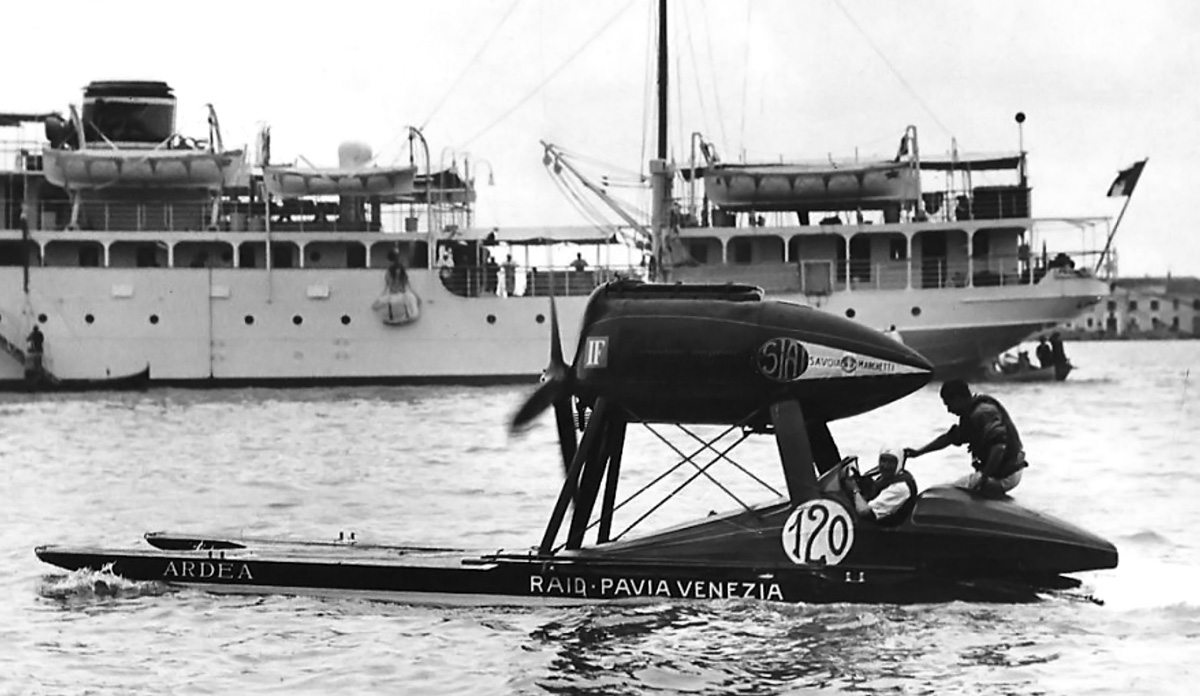
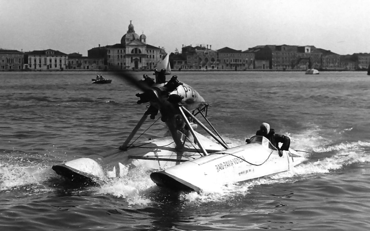
Fernando Venturi and Paolo Mora’s FIAT-powerd Saliman in 1939. The idroscivolante finished the race in third place and went on to set a short-lived speed record of 49.692 mph (79.971 km/h) in July 1939. Santa Maria della Presentazione (Le Zitelle) is in the background. (image via Three Point Hydroplanes)

In August 1951, Franco Venturi, Fernando’s son, set an 800 kg (1,764 lb) class speed record of 97 mph (156 km/h) on Lake Sabaudia. The idroscivolante used for this record run was the same two-hulled catamaran used by Goffredo Gorini in 1939 to win the Raid Pavia-Venezia and establish an 800 kg speed record. However, the idroscivolante was modified with a three-blade, metal propeller attached to the Wright R-975 Whirlwind engine. With idroscivolanti banned from the Raid Pavia-Venezia, Franco Venturi eventually donated the machine to the Museo della Scienza e della Tecnologia “Leonardo da Vinci” (Museum of Science and Technology “Leonardo da Vinci”) in Milan, Italy, where it is currently preserved.

1951 Franco Venturi Gorini-Wright

The Gorini/Wright idroscivolante used to set a speed record in 1939 by Goffredo Gorini at 91 mph (147 km/h) and in 1951 by Franco Venturi at 97 mph (156 km/h). (image via Museo della Scienza e della Tecnologia)

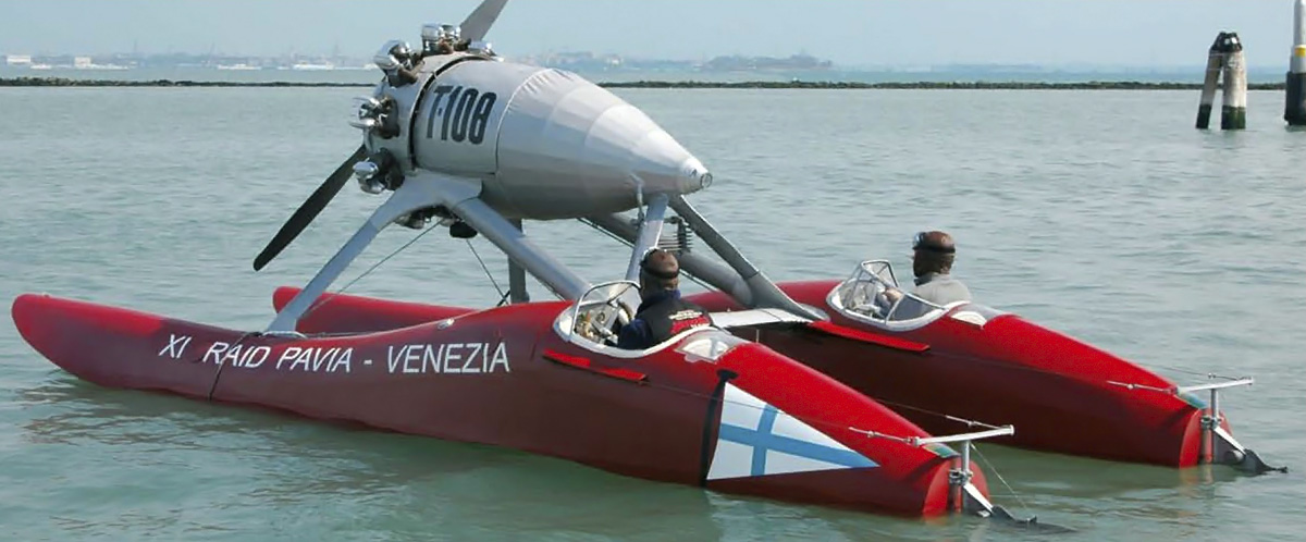
Prospero Freri managed to save the idroscivolante that he drove to second place finishes in 1937, 1938, and 1939. Numbered 108 and later T-108, the racer had deteriorated over the years. After Freri passed away in 1965, his heirs donated T-108 to the Civico Museo Navale Didattico di Milano (Civic Museum of Naval Education of Milan) in 1967. In 2006, T-108 underwent a seven month restoration by the Dalla Pietà boatyard in Malcontenta. At the beginning of the restoration, T-108 had “XII Raid Pavia-Venezia” painted on the hull, indicating Freri had prepared the idroscivolante for the 1940 race (the 12th Raid Pavia-Venezia). After the restoration, the hull was painted “XI Raid Pavia-Venezia” (indicating the 1939 race) to eliminate any confusion. T-108 is currently on display in the Museo della Scienza e della Tecnologia “Leonardo da Vinci”.

Sadly, there is very little information on the idroscivolanti, and what information can be found is occasionally contradictory. The timeline in this article was developed by cross referencing existing information with contemporary photos and videos. While every effort was made to maintain accuracy, there is no guarantee the article is entirely correct. Most of material for this article came from Three Point Hydroplanes, a historical archive of Italian hydroplanes.

2007 T-108 Freri SIAI-AR

The Alfa Romeo D.2-powered idroscivolante driven by Prospero Freri and Salvatore Flamini to second place in the 1937, 1938, and 1939 races. It was restored to its 1939 Raid Pavia-Venezia configuration in 2007. (image via Dalla Pietà Yatch)

Idroscivolanti results in the Raid Pavia-Venezia

1930
1) Franco Mazzotti and Guido Cattaneo in the SIAI/Isotta Fraschini
8:10:35 averaging 31.462 mph (50.633 km/h)

1931
1) Franco Mazzotti and Guido Cattaneo in the SIAI/Isotta Fraschini
6:52:54 averaging 38.309 mph (61.653 km/h)
2) Theo Rossi and Alfredo Stracconi in the Passarin/FIAT
7:38:43 averaging 33.648 mph (54.151 km/h)

1932
1) Attilio Biseo and Gino Bertoli in the SIAI/FIAT
5:27:26 at 47.138 mph (75.862 km/h)
DNF) Theo Rossi and Alfredo Stracconi in the Passarin/FIAT

1933
1) Theo Rossi and Guido Cattaneo in the SIAI/Isotta Fraschini
6:37:14 averaging 40.639 mph (65.402 km/h)
DNF) Marcello Visconti di Modrone and Franco Mazzotti in the SIAI/FIAT

1934
1) Attilio Biseo and Renato Donati in the SIAI/Farina
5:44:08 averaging 47.188 mph (75.942 km/h)
DNF) Theo Rossi and Guido Cattaneo in the SIAI/Isotta Fraschini
DNF) Aldo Salom and Dino Celli in the Celli/SPA

1935
1) Theo Rossi and Guido Cattaneo in the SIAI/Isotta Fraschini
5:01:50 averaging 53.483 mph (86.073 km/h)
2) Goffredo Gorini and Francesco Bertoli in the Laboratorio Sperimentale Regia Aeronautica/Alfa Romeo
5:12:30 averaging 51.652 mph (83.126 km/h)
4) Aldo Salom and Dino Celli in the Celli/SPA
6:26:18 averaging 41.789 mph (67.253 km/h)
6) Renato Donati and Federico Borromeo in the Laboratorio Sperimentale Regia Aeronautica/Alfa Romeo
7:20:28 averaging 36.650 mph (58.982 km/h)

1936
1) Theo Rossi and Guido Cattaneo in the SIAI/Isotta Fraschini
4:45:02 averaging 56.576 mph (91.051 km/h)
2) Vito Mussolini and Carlo Maurizio Ruspoli in the SIAI/Farina
5:29:02 averaging 44.967 mph (72.367 km/h)
DNF) Goffredo Gorini and Renato Donati in the Laboratorio Sperimentale Regia Aeronautica/Alfa Romeo

1937
1) Goffredo Gorini and Renato Donati in the SIAI/Alfa Romeo
4:47:32 averaging 56.143 mph (90.354 km/h)
2) Prospero Freri and Salvatore Flamini in the CNA/Alfa Romeo
4:57:59 averaging 54.175 mph (87.186 km/h)
3) Theo Rossi and Guido Cattaneo in the SIAI/Isotta Fraschini
5:29:22 averaging 49.013 mph (78.878 km/h)

1938
1) Goffredo Gorini and Marco Ponzalino in the SIAI/Alfa Romeo
4:11:28 averaging 64.193 mph (103.308 km/h)
2) Prospero Freri and Salvatore Flamini in the CNA/Alfa Romeo
5:34:40 averaging 48.236 mph (77.629 km/h)
3) Vito Mussolini and Luciano Agosti in the SIAI/Farina
6:37:32 at 40.614 mph (65.352 km/h)
8) Marco Celli and Aldo Tassinari in the Celli/Walter
8:13:11 averaging 32.733 mph (52.678 km/h)
9) Aldo Salom and Bruno Rocca in the Celli/Isotta Fraschini
9:25:44 averaging 28.535 mph (45.922 km/h)
DNF) Theo Rossi and Guido Cattaneo in the SIAI/Isotta Fraschini

1939
1) Goffredo Gorini and Marco Ponzalino in the Gorini/Wright
4:19:16 averaging 62.264 mph (100.205 km/h)
2) Prospero Freri and Salvatore Flamini in the Gorini/Freri/Alfa Romeo
4:42.29 averaging 57.148 mph (91.970 km/h)
3) Fernando Venturi and Paolo Mora in the Saliman/FIAT
6:10:54 averaging 43.524 mph (70.045 km/h)
4) Vito Mussolini and Luciano Agosti in the SIAI/Farina
6:16:13 averaging 42.915 mph (69.065 km/h)

Sources:
http://www.threepointhydroplanes.it/raid-pavia-venezia_r1_en.htm (and numerous pages, images, and videos therein)
http://www.museoscienza.org/museo/patrimonio/idroscivolanteT108.asp
http://www.museoscienza.org/dipartimenti/catalogo_collezioni/scheda_oggetto.asp?idk_in=ST120-00498
http://www.pionieredellanautica.it/index.php?option=com_content&view=article&id=47&Itemid=55
Fernando Venturi 1939 Record Run (YouTube)
Geoffredo Gorini 1939 Record Run (YouTube)
Franco Venturi 1951 Record Run (YouTube)
Aerosphere 1939 by Glenn D. Angle (1940)
Aeronuatica Militare Museo Storico Catalogo Motori by Oscar Marchi (1980)

Hispano-Suiza 24Y Type 90 side

Hispano-Suiza 24Y (Type 82 and Type 90) Aircraft Engine

By William Pearce

In 1936, the Ministère de l’Air (French Air Ministry) issued a specification for a 2,000 hp (1,491 kW) engine intended to power a flying boat for transatlantic service. The aircraft was to carry at least 40 passengers and 1,100 lb (500 kg) of cargo 3,725 miles (6,000 km) against a 37 mph (60 km/h) headwind. Hispano-Suiza already had its 12Y engine of 1,000 hp (746 kW) in production and was investigating ways to effectively double that engine. Their design efforts led to the 24-cylinder Hispano-Suiza 24Y aircraft engine.

Hispano-Suiza 24Y Type 82 front 2

The Hispano-Suiza 24Y Type 82 24-cylinder H engine on display in the Polish Aviation Museum in Krakow. The Type 82 was intended for use with contra-rotating propellers; however, its original propeller shaft is missing.

The idea behind the 24Y engine was to utilize as many 12Y engine components as possible. The Hispano-Suiza 12Y engine was a liquid-cooled V-12. Each bank of six cylinders was cast en bloc with an integral cylinder head. The 12Y had a 5.91 in (150 mm) bore, a 6.69 in (170 mm) stroke, and a total displacement of 2,200 cu in (36.05 L). The 12Y-50 was one of the last and most powerful versions of the engine; it produced 1,100 hp (820 kW) at 2,500 rpm.

The 24Y engine’s configuration was a vertical H-24: two cylinder banks were mounted vertically above the crankcase, and two cylinder banks were below. A crankshaft served each upper and lower cylinder bank pair. Four aluminum 12Y-50* cylinder blocks were mounted on the 24Y’s crankcase. Each cylinder block included two valves per cylinder, a single overhead camshaft, and the camshaft’s vertical drive shaft. The 7 to 1 compression pistons were connected to the hollow, one-piece crankshaft via fork-and-blade connecting rods, and all components were from the 12Y engine. Each crankshaft had six throws and was supported by seven main bearings. The two-piece, aluminum crankcase was formed by an upper and lower half and was unique to the 24Y.

Hispano-Suiza 24Y Type 90 rear

Rear view of the Hispano-Suiza 24Y (Type 90) showing the engine’s four magnetos, two superchargers, four fuel pumps, and two coolant pumps.

At the rear of the engine, each crankshaft drove a single-speed supercharger at 10 times crankshaft speed. The superchargers gave the engine 2.3 psi (.16 bar) of boost. Separate intake manifolds led from each supercharger to the upper and lower cylinder banks on one side of the engine. Three carburetors were positioned along each intake manifold. Each of the engine’s 12 carburetors supplied the air/fuel mixture to a pair of cylinders.

The two spark plugs per cylinder were fired by four magnetos driven from the rear of the engine. Two magnetos were located above each supercharger. Four fuel pumps were mounted below and between the superchargers. The left and right sides of the engine had separate coolant systems, and a coolant pump was located below each supercharger.

At the front of the engine, each crankshaft had a 28-tooth gear that engaged a 55-tooth propeller gear. This combination created a .509 to 1 gear reduction for the propeller shaft. Between each crankshaft and its power gear was a Sarazin torsional vibration damper. Two versions of the 24Y were built, and they differed in their propeller drive. The 24Y Type 82 was designed to power contra-rotating propellers. In this engine, one crankshaft drove the inner propeller shaft while the other crankshaft drove the outer propeller shaft. The 24Y Type 90 was designed to power a single-rotation propeller and was available with either a normal length or extended gear reduction nose case. Some sources state the Type 90 had accommodations for a cannon to fire through the propeller shaft, but photos indicate this was unlikely.

Hispano-Suiza 24Y Type 90 side

Hispano-Suiza 24Y Type 90 engine with its extended gear reduction case for a single rotation propeller. This engine was displayed at the 1938 Salon de l’Aéronautique in Paris. Note the three carburetors for each cylinder bank.

The Hispano-Suiza 24Y had a 5.91 in (150 mm) bore and a 6.69 in (170 mm) stroke. The engine’s total displacement was 4,400 cu in (72.10 L). The 24Y produced 2,200 hp (1,641 kW) at 2,500 rpm for takeoff. Max power was 2,000 hp (1,491 kW) at 2,400 rpm at 10,827 ft (3,300 m), and cruising power was 1,500 hp (1,119 kW) at 2,250 rpm at 10,827 ft (3,300 m). The engine had a specific fuel consumption of .50 lb/hp/hr (304 g/kW/hr). The Type 82 was 6.46 ft (1.97 m) long, 3.05 ft (.93 m) wide, and 4.27 ft (1.30 m) tall. The engine weighed 2,204 lb (1,000 kg). The Type 90 had the same width and height as the Type 82 but was 3.38 ft (1.03 m) longer with the extended gear reduction case, for a total length of 9.84 ft (3.00 m). The Type 90’s weight was listed as 2,161 lb (980 kg).

Exactly when the 24Y was first run has been lost to history. The engine made its public debut in November 1938 at the Salon de l’Aéronautique (Air Show) in Paris, France. A Type 90 engine was displayed there, and it attracted a lot of attention. Unfortunately for Hispano-Suiza, that attention did not translate into sales. War in Europe was imminent by 1939, and Hispano-Suiza had turned its attention to developing the new 12Z engine. The 12Z was the next evolutionary step beyond the 12Y for Hispano-Suiza’s V-12 engines. War would interrupt the 12Z’s development, but the 12Z would later inspire another 24-cylinder engine known as the 24Z, which was configured like the 24Y. It is doubtful that the 24Y was ever flown.

Hispano-Suiza 24Y Type 82 side

The preserved 24Y Type 82 engine is missing many components. Note the vertical drive shaft for the camshaft at the end of each cylinder bank. (Polish Aviation Museum image)

Only a small number of 24Y engines were built—probably just one Type 82 and one Type 90 with an extended gear reduction case. Having disappeared during World War II, the disposition of the Type 90 is not known. The Type 82 wound up in Poland at the end of World War II. Most likely, it was part of Herman Goering’s aviation collection that was moved to Poland late in the war to keep it from being damaged during Allied bombing raids. The Hispano-Suiza 24Y Type 82 engine is currently preserved (without its original propeller shaft) and on display in the Polish Aviation Museum in Krakow.

*Some sources state that 12Y-51 cylinder blocks were used on the 24Y. The 12Y-50 and 12Y-51 were basically the same engine, the only difference being the crankshaft rotation. When viewed from the rear, the 12Y-50 rotated counter clockwise; the 12Y-51 rotated clockwise. The cylinder blocks of the 12Y-50 and 12Y-51 engines were the same.

Hispano-Suiza 24Y Type 82 rear

The supercharger impellers can be seen in this view of the 24Y Type 82. Although the magnetos are gone, the fuel pumps and one coolant pump remain. (Polish Aviation Museum image)

Sources:
Aircraft Engines of the World 1941 by Paul H. Wilkinson (1941)
Hispano Suiza in Aeronautics by Manuel Lage (2004)
Jane’s All the World’s Aircraft 1939 by C. G. Grey and Leonard Bridgman (1939)
– “Some Trends in Engine Design” Flight (8 December 1938)
http://www.muzeumlotnictwa.pl/zbiory_sz.php?ido=121&w=a

de Havilland DH91 Forbisher front

De Havilland DH.91 Albatross Transport

by William Pearce

In the mid-1930s, the de Havilland Aircraft Company (de Havilland ) sought financial support from the British Air Ministry to develop a new transport aircraft. De Havilland felt that Britain was not developing transport aircraft of the same performance level as those from the United States. On 21 January 1936, the Air Ministry ordered two of the new de Havilland transports as transatlantic mailplanes under Specification 36/35. Five additional aircraft were ordered by Imperial Airways Ltd. and would be completed as passenger transports. The mailplane and airliner versions had only minor differences, and both aircraft were designated DH.91 Albatross.

de Havilland DH91 Forbisher flight

The flagship of Imperial Airways F class: the de Havilland DH.91 Albatross ‘Frobisher.’ Its clean lines can be seen in the image above.

Designed by Arthur E. Hagg, the Albatross was an exceptionally clean, four-engine monoplane constructed almost entirely of wood. The long, circular fuselage had a steady taper toward the tail and was made of balsa wood sandwiched between thin layers of either cedar or birch, depending on location. The wood layers were cemented together and formed under pressure. Cabin construction allowed for pressurization, but such a system was never designed for the aircraft. The wing of the Albatross was constructed as one piece from a spruce structure covered with two layers of diagonal spruce planking. The thin wing was virtually sealed and would provide some level of buoyancy in the event of a water landing. The aircraft’s control surfaces were fabric-covered.

The Albatross had twin tails. Originally, the vertical stabilizers were positioned near the fuselage, about a third of the way along the horizontal stabilizer. Due to control issues, the tails were redesigned and positioned at the ends of the horizontal stabilizer. The aircraft used a conventional taildragger landing gear arrangement. The main wheels retracted inward and were fully enclosed in the wing’s center section. The tailwheel did not retract.

de-Havilland-DH91-Faraday-early

The first Albatross prototype. Note its original tail and how close the vertical stabilizers are to the fuselage. This mailplane version would later be named ‘Faraday.’

Four de Havilland Gipsy Twelve (King I) engines powered the Albatross. The Gipsy Twelve was an air-cooled, supercharged, inverted, V-12 engine. The engine had a 4.65 in (118 mm) bore, a 5.51 in (140 mm) stroke, and a total displacement of 1,121 cu in (18.4 L). The Gipsy Twelve produced 525 hp (391 kW) at 2,600 rpm for takeoff power, 425 hp (317 kW) at 2,400 rpm for maximum climbing power, and 320 hp (239 kW) at 2,200 rpm for maximum economical cruse power. Each engine was housed in a very tight-fitting, streamlined cowling. Cooling air was brought in via pressure-ducts in the wing’s leading edge. The ducts were located in the propeller’s slipstream on both sides of each engine nacelle. The cooling air flowed forward along the outer side of the cylinders, from the back of the engine to the front. The air was forced through the cylinders’ cooling fins and into the Vee of the engine, where an exit flap on the bottom of the cowling allowed the air to escape. The opening of the exit flap controlled the engine temperature. Each engine turned a two-blade, constant-speed, 10 ft 6 in (3.2 m) diameter de Havilland propeller via a .66 gear reduction.

The basic structure of the mailplane and airliner versions of the Albatross were the same, but the aircraft did have their differences. The mailplane was designed to carry 1,000 lb (454 kg) of mail 2,500 mi (4,023 km) against a 40 mph (64 km/h) headwind, while the airliner was designed to carry 22 passengers and four crew 1,000 mi (1,609 km). The mailplane had four cabin windows on each side of its fuselage, compared to six for the airliner version. The mailplane utilized split flaps, while the airliner used slotted flaps. The mailplane Albatross had four 330 gal (1,250 L) fuel tanks mounted in the cabin, while the airliner had one 270 gal (1,022 L) and one 170 gal (644 L) fuel tank mounted under the cabin floor. The mailplane had two 9 gal (7.5 L) oil tanks per engine; the airliner had just one oil tank per engine.

de Havilland DH91 Forbisher front

The cooling-air ducts in the wing’s leading edge can be seen in this view of ‘Frobisher.’ Each duct brought in air to the nearest cylinder bank. Note the landing gear wheel wells and the hinged cover on the main wheels.

The Albatross had a wingspan of 105 ft (32.0 m) and was 71 ft 6 in (21.8 m) long. The mailplane had a top speed of 222 mph (357 km/h) at 8,700 ft (2,652 m) and a maximum economical cruse speed of 204 mph (328 km/h) at 11,000 ft (3,353 m). Its maximum range was 3,300 mi (5,311 km), and its gross weight was 32,500 lb (14,742 kg). The aircraft had a 550 fpm (2.8 m/s) climb rate and a ceiling of 15,100 ft (4,602 m).

The airliner version had a top speed of 225 mph (362 km/h) at 8,700 ft (2,652 m) and a maximum economical cruse speed of 210 mph (378 km/h) at 11,000 ft (3,353 m). Its maximum range was 1,040 mi (1,634 km), and its gross weight was 29,500 lb (13,381 kg). The aircraft had a 710 fpm (3.6 m/s) climb rate and a ceiling of 17,900 ft (5,456 m).

de Havilland DH91 Forbisher rear

This view of ‘Frobisher’ shows the additional windows incorporated into the airliner version of the Albatross. The revised tail is also apparent.

The Albatross mailplanes were built first, and the initial prototype flew for the first time on 20 May 1937. Robert John Waight was the pilot for the first flight. By October, the need to redesign the tails was evident, and the new tail fins were installed on the ends of the horizontal stabilizer. After the modification, the aircraft was registered as G-AEVV on 3 January 1938. On 31 March 1938, the Albatross suffered a belly landing due to a landing gear issue. Once repaired, G-AEVV became part of Imperial Airways in August 1939. All DH.91s were part of Imperial Airways F (Frobisher) class of aircraft and were given names starting with the letter “F.” G-AEVV was named Faraday. When Imperial Airways was merged with British Airways Ltd. in 1940 to form the British Overseas Airways Corporation (BOAC), the ownership of all DH.91s was eventually transferred to BOAC. Faraday was transferred to BOAC on 17 June 1940. On 1 September 1940, Faraday was impressed into service (as AX903) during World War II as a transport shuttle flying between Great Britain and Iceland. While landing at Reykjavik, Iceland on 11 August 1941, the aircraft collided with a Fairey Battle and was damaged beyond repair. Fortunately, the five people onboard the Albatross escaped unharmed. Some records claim the accident occurred on 11 August 1940, but this does not fit the timeline, especially since the date of impressment is recorded as 1 September 1940.

The second mailplane was registered as G-AEVW and named Franklin. On 27 August 1938, the aircraft’s rear fuselage broke in two during overload landing tests, revealing a structural weakness. The aircraft was repaired, and the changes were incorporated into the other Albatross aircraft. G-AEVW was transferred to BOAC on 8 July 1940. Like Faraday, Franklin was impressed into service (as AX904) on 1 September 1940 and was damaged beyond repair in a landing accident at Reykjavik. The mishap occurred on 7 April 1942 when the aircraft’s landing gear collapsed. The four people onboard were not injured.

de Havilland DH91 Forbisher side

The DH.91 was a very graceful and aerodynamic aircraft. Note the sleek engine installation and the cooling-air exit flaps under the engine nacelles.

The first Albatross airliner was registered as G-AFDI and given the name Frobisher. It was delivered in October 1938 and served as the flagship for Imperial Airways. The aircraft started experimental service in December and averaged 219 mph on its first service flight from Croydon, England to Cairo, Egypt. The aircraft was transferred to BOAC on 22 August 1940. Frobisher was destroyed during a German air raid at the Bristol (Whitchurch) Airport on 20 December 1940.

The second airliner was registered as G-AFDJ and named Falcon. It was delivered to Imperial Airways in November 1938 and entered service in January 1939. The aircraft was transferred to BOAC on 27 August 1940. Falcon was scrapped in August 1943 after the loss of Fortuna (see below) and because the spare parts supply for the Albatross aircraft had been depleted.

The third airliner was registered as G-AFDK and named Fortuna. It was in service by mid-1939 and was transferred to BOAC on 27 August 1940. Fortuna crashed on approach to Shannon Airport in Ireland on 16 July 1943. The aircraft’s wing started to break up, and Fortuna crash landed short of the runway. All fourteen people on the aircraft survived the crash. This accident precipitated the last two surviving DH.91s, Falcon and Fiona (see below), to be removed from service.

de-Havilland-DH91-Franklin

The two Albatross mailplanes served as transports during World War II, and both were lost in separate landing accidents at Reykjavik, Iceland. ‘Franklin,’ the second mailplane  is seen above in its wartime camouflage.

The fourth airliner was registered as G-AFDL and named Fingal. It entered service for Imperial Airways in 1939 and was transferred to BOAC on 29 August 1940. The aircraft was lost on 6 October 1940 while making an emergency landing near Pucklechurch, England because of a fractured fuel line. Fingal hit a farmhouse during the forced landing and was damaged beyond repair, but none of the three people onboard were injured.

The last airliner was registered as G-AFDM and named Fiona. The aircraft entered service with Imperial Airways in 1939. The aircraft was transferred to BOAC on 22 August 1940 and continued in service until being withdrawn after the Fortuna crash. Fiona was scrapped along with Falcon in August 1943.

The de Havilland DH.91 Albatross was a beautiful aircraft that performed well in service. Part of its downfall can be attributed to its production right before World War II. It is rather remarkable to consider that four of the aircraft crashed during the landing phase of flight but that no one was killed in any of the accidents. While the Albatross cannot be considered a success, the techniques used in the Albatross’ wooden construction were applied directly to the incredibly successful World War II-era DH.98 Mosquito. Hagg went on to design the Napier-Heston Racer, and some of the Albatross’ streamlining traits can be seen in that aircraft.

de Havilland DH91 Fortuna

While landing in Shannon, Ireland, the wing of ‘Fortuna’ (seen above) began to break apart. The aircraft crashed short of the runway, but no lives were lost. Due to the crash and lack of spare parts, the two remaining DH.91s were withdrawn from service. Note the Bristol Beaufighter in the distance.

Sources:
– “The Albatross in Detail” Flight (17 November 1938)
De Havilland Aircraft since 1909 by A. J. Jackson (1987)
Shannon Airport: A Unique Story of Survival by Valerie Sweeney (2004/2015)
– “Cooling the Gipsy Twelve” Flight (31 March 1938)
http://aviation-safety.net/database/record.php?id=19400811-0
http://aviation-safety.net/database/record.php?id=19420407-0
http://aviation-safety.net/database/record.php?id=19401220-0
http://aviation-safety.net/database/record.php?id=19401006-0

Deperdussin-de Feure store rear

Deperdussin-de Feure Model 2

By William Pearce

Georges de Feure (originally Georges Joseph van Sluijters) was born in Paris, France to a Dutch father and Belgian mother. De Feure was an artist and designer but turned his attention to aviation after Louis Blériot made his historic flight across the English Channel on 25 July 1909. Armand Deperdussin was born in Belgian but lived in Paris. Deperdussin had made a fortune importing silk for French stores. Like de Feure, Deperdussin had become interested in aviation after Blériot’s Channel crossing. In 1909, the two men joined forces to build aircraft; de Feure was the designer, and Deperdussin provided financial backing.

Deperdussin-de Feure store front

The Deperdussin-de Feure model 2 hangs in the Au Bon Marché department store in Paris. Note the number “2” on the aircraft’s nose and the single landing skid.

Many sources refer to the partnership as De Feure-Deperdussin (DFD) and call the aircraft DFD1 and DFD2. However, a French patent for the for the pair’s second aircraft cites the business as the Société A. Deperdussin et de Feure, or the A. Deperdussin and de Feure Company. This substantiates other sources that refer to the association as Deperdussin-de Feure, which will be the name used in this article. Subsequent patents listed Deperdussin and de Feure individually and include Louis Béchereau when applicable. Béchereau was an early French aeronautical engineer who was hired to assist with Deperdussin-de Feure aircraft design.

The first aircraft designed by Deperdussin-de Feure has been described as a pusher with an arrow-shaped wing. This aircraft was not built, but it did serve as the basis for the pair’s second aircraft. Deperdussin-de Feure applied for a patent on 19 November 1909 that described their second aircraft; they were granted French patent 409,715 on 24 February 1910.

Deperdussin-de Feure store rear

This rear view of the Deperdussin-de Feure suspended over the store’s toy department shows there is no engine installed in the aircraft, and the wing is absent of flight controls. Note the two wide, two-blade, contra-rotating propellers.

The Deperdussin-de Feure model 2 aircraft was a pusher design that had a rear main wing and a front canard. The tail-first aircraft was made up of a wooden framework covered with fabric. In the middle of the fuselage was a radiator to cool the water from the four-cylinder engine. The radiator consisted of numerous copper tubes that arched from one side of the aircraft to the other; the radiator was modified several times throughout the life of the aircraft.

The engine was enclosed in a metal cowling and sat just behind the radiator. Reportedly, the engine produced 65 hp (48 kW) at 2,300 rpm and weighed 165 lb (75 kg). The manufacturer of the engine is not known, and its specifics do not match any engine from the time period. However, the engine does resemble four-cylinder engines built by Panhard-Levassor around that time, although the Panhard-Levassor engines produced peak power at a lower rpm and were heavier.

Deperdussin-de Feure Avialogs

The completed Deperdussin-de Feure with revised wing at Chamdry, France. Note the various trusses above and below the wings and that a second landing skid has been added. The two two-blade, contra-rotating propellers are still present. (Image via Avialogs.com)

A propeller shaft extended from the engine, traveled under the pilot’s seat, and terminated at a gearbox in the rear of the aircraft. The gearbox transferred the engine’s power to a set of contra-rotating propellers. The patent noted that the contra-rotating propellers would cancel engine torque and increase the aircraft’s stability. The patent also stated that the pitch of the rear propeller was greater than that of the front propeller to make efficient use of the increased airflow generated by the first propeller. Originally, two two-blade propellers were installed, but these were later replaced by two four-blade propellers.

According to the patent, the curvature of the wings’ inner sections could be warped symmetrically by the pilot to increase lift or drag. The outer sections of the Deperdussin-de Feure’s wings could be warped asymmetrically for roll control. The aircraft’s canard featured an all-moving elevator with an all-moving rudder positioned above.

Deperdussin-de Feure cockpit

The extensive trusswork for the Deperdussin-de Feure’s wings is displayed in this photo. The inclined track for the wing can be seen in the middle of the photo, just behind the first truss. Note the two two-blade propellers.

While the patent drawing shows a passenger seat mounted between the pilot’s seat and the engine, it does not appear that such accommodations were ever installed. The pilot’s seat was essentially mounted on top of the fuselage. A wheel in front of the pilot controlled wingtip warping for roll control. Wheels mounted on either side of the pilot controlled the elevator and inner wing warping. The rudder was controlled by a foot-operated bar.

The aircraft was supported by four wheels attached near a skid under the aircraft. The front wheels were steerable, and when the aircraft landed, all the wheels would pivot upward, allowing the skid to contact the ground. The friction created by the skid would slow the Deperdussin-de Feure aircraft to a stop. Originally, the aircraft had one skid, but a second was added later.

Appearing mostly complete, the Deperdussin-de Feure aircraft was displayed at the Au Bon Marché department store in Paris starting 12 December for the 1909 Christmas season. However, the aircraft lacked its engine, and 26 ft (8 m) long fake wings were installed just for the display. The aircraft was suspended from the ceiling above the store’s toy department and had a mannequin in the pilot’s seat. The aircraft’s unfinished components and its location above the toy department gave rise to the belief that it was just an elaborate model, and in a sense it was.

Deperdussin-de Feure side Chambry

The Deperdussin-de Feure ready for a flight attempt. It is difficult to determine which propellers are installed on the aircraft in this photo.

After the display, the aircraft was moved to a hangar at the Chambry airport 95 mi (150 km) northeast of Paris in March 1910. The hangar had been specially built and was designed and equipped under the supervision of Louis Blériot. By this time, the aircraft’s engine was installed, and an additional landing skid was added. With a span over 39 ft (12 m), the Deperdussin-de Feure’s true wings were fitted along with their wooden support trusses. The many changes incorporated gave rise to the belief that this was a different aircraft than the one displayed in the department store, and in a sense it was.

With the design of the new wings and their support trusses, the idea of increasing the wings’ lift by altering the curvature of the inner wing sections was discarded. A new method to increase lift was devised that altered the position and angle of the entire wing. Outlined in French patent 413,071 (applied for on 26 February 1910 and issued on 18 May 1910), each wing was attached to the aircraft’s fuselage via an angled track. The trusses held the left and right wings together, and the track allowed the wings to shift position relative to the fuselage. As the wings moved fore or aft, so too would the aircraft’s center of gravity. The track was inclined toward the front of the aircraft. As the wings moved forward, their angle of attack would increase, altering their center of pressure. Exactly how the system was operated is not recorded, and one can only imagine how wings shifting in position and angle would affect an aircraft in flight, especially in the early days of aviation.

Deperdussin-de Feure side

The Deperdussin-de Feure aircraft has now been modified with a ventral rudder and two narrow, four-blade, contra-rotating propellers.

The Deperdussin-de Feure aircraft was made ready for flight, and claims were circulated through the press that it could carry 661 lb (300 kg), had a 4,920 ft (1,500 m) ceiling, and that the military was interested in the machine. Many bystanders from nearby Laon would come out to Chambry in the hope of seeing de Feure pilot the aircraft into the air. Unfortunately, they were rewarded with only small hops of no more than 1.6 ft (.5 m). Four-blade propellers and an auxiliary, all-moving rudder positioned below the pilot were installed sometime during this period. In addition, a conventional cored radiator was tried. Tests at Chambry continued into June 1910. The aircraft was then moved to the Rheims airport 30 mi (50 km) southeast of Chambry, but a successful flight was still not achieved.

Frustrated by the lack of success, Deperdussin and de Feure had gone their separate ways by the end of 1910. Deperdussin started another aircraft company with Béchereau as the head designer. The company became the Société Pour L’Aviation et ses Dérivés (Society for Aviation and its Derivatives), better known as SPAD, and created some of the best aircraft of World War I. De Feure returned to his roots of design and artistry. Although he did envision a few other aircraft, only those meant as theater sets and costumes were constructed.

Deperdussin-de Feure rear Chambry

This rear view of the Deperdussin-de Feure displays the aircraft’s wing trusses, propellers, flight controls, and all-moving ventral rudder.

Sources:
Nederlandse Vliegtuigen Deel 1 by Theo Wesselink (2014)
– “Aéroplane monoplane” French patent 409,715 by Société A. Deperdussin et de Feure (granted 24 February 1910)
– “Perfectionnements aux aéroplanes” French patent 413,071 by Armand-Jean-Auguste Deperdussin, Georges-Joseph de Feure, and Louis Béchereau (granted 18 May 1910)
French Aeroplanes Before the Great War by Leonard E. Opdycke (2004)
http://www.avialogs.com/index.php/avialogs/100-years-old-unpublished-deperdussin-photos-found-at-garage-sale.html
https://en.wikipedia.org/wiki/Georges_de_Feure
https://en.wikipedia.org/wiki/Armand_Deperdussin

Piaggio P16

Piaggio P.16 Bomber

By William Pearce

Rinaldo Piaggio founded the Rinaldo Piaggio SpA in Genoa, Italy in 1884. The company was renamed Piaggio & C. SpA (Piaggio) in 1887. Piaggio originally furnished ship interiors and manufactured railroad equipment but turned to the licensed construction of aircraft during World War I. Piaggio decided to manufacture aircraft of its own design in 1923. That same year, Piaggio purchased the Pegna-Bonmartini company and acquired the services of aeronautical engineer Giovanni Pegna. By the early 1930s, Piaggio looked to create military and commercial aircraft that incorporated modern advancements in design and manufacture. By 1932, Pegna had designed the Piaggio P.16 bomber.

Piaggio P16 1932

A circa 1932 drawing of the Piaggio P.16. Note the unique wing shape that was not used on the actual aircraft prototype.

The P.16 possessed many features used for the first time on a Piaggio aircraft: tri-motor design, variable-pitch propellers, all metal construction, and retractable main landing gear. The P.16 was powered by three Piaggio P.IX RC engines—one in the nose of the aircraft and one on each wing. The P.IX RC engine was a nine-cylinder radial developed from the French Gnome-Rhône Mistral 9K. The engine displaced 1,517 cu in (24.9 L) and produced 610 hp (455 kW). The metal, two-blade propellers were developed by Corradino D’ Ascanio and built by Piaggio.

The wings of the P.16 were of all duralumin construction, while the fuselage and tail had a steel tube frame. The front and upper sections of the fuselage were covered in duralumin. The aircraft’s control surfaces and the rear sides and lower sections of the fuselage were fabric-covered. The P.16’s original inverted gull wing design consisted of a very long wing root that ran from just behind the cockpit back to the tail. The wing continuously tapered toward its tip, which had a very narrow cord. The wing used on the actual aircraft maintained the same basic shape of the earlier design but extended back only to the middle of the aircraft’s fuselage and did not have such a narrow tip. The thickest part of the wing was by the engine nacelles, after which it narrowed toward the tip and toward the fuselage. The relatively thin wing roots helped reduce buffeting of the aircraft’s tail.

Piaggio P16

The completed P.16 with its revised wing. Just below the cockpit side window is the circular window in the cockpit access door.

On each side of the aircraft, two braces extended from the lower engine nacelle to the lower fuselage. Hydraulically operated flaps extended out from the engine nacelles to about mid-span, and ailerons occupied the rest of the wing’s trailing edge. The leading edge of the outer wing sections had retractable slats to improve the aircraft’s control at low-speed. The main landing gear retracted aft and was fully enclosed in the engine nacelles. The steerable tailwheel did not retract but was enclosed in an aerodynamic fairing.

The P.16 had a five-man crew. The pilot and copilot sat side-by-side in the cockpit. Behind the cockpit was a bomb bay that accommodated 2,200 lb (1,000 kg) of bombs. Some sources indicate the bombardier was in the lower forward fuselage just below the cockpit. Other sources state the bombardier was behind the bomb bay in the middle of the aircraft. Given the aircraft’s layout, the mid-position seems more likely. Along the upper mid-fuselage was a retractable turret that housed one 7.7 mm machine gun. In the rear of the fuselage and just below the vertical stabilizer was another 7.7 mm machine gun position. Two additional 7.7 mm machine guns were forward firing. Most sources state the guns were located in the wing roots, but that would require the guns to be located right next to the cockpit and to fire through the propeller arc. It is possible that the forward firing machine guns were housed in the outer wing sections, but there is no obvious indication of their location.

Piaggio P16 side

The distinct position of the rear gunner is illustrated in this side view of the P.16. The retracted dorsal turret can be seen just behind the wing root on the top of the fuselage.

The cockpit was accessible by a door on each side of the aircraft, just under the cockpit side windows and in front of the wing. Another door just under the trailing edge of the left wing provided access to the rear fuselage.

The P.16 had a wingspan of 72.2 ft (22.0 m) and was 44.0 ft (13.4 m) long. The aircraft’s empty weight was 12,346 lb (5,600 kg), and its loaded weight was 18,629 lb (8,450 kg). Its maximum speed was 224 mph (362 km/h) at sea level and 249 mph (400 km/h) at 16,404 ft (5,000 m). The aircraft had a cruising speed of 201 mph (324 km/h) and a landing speed of 65 mph (105 km/h). The P.16 could climb to 19,685 ft (6,000 m) in 17 minutes. The aircraft’s range was 932 miles (1,500 km) with a maximum bomb load and 1,243 miles (2,000 km) with a 1,100 lb (500 kg) bombload.

Piaggio P16 rear

This rear view of the P.16 shows the inverted gull wing and the struts running from the engine nacelles to the fuselage. Note the aircraft’s flaps and ailerons.

The P.16 was officially ordered on 4 July 1933, but construction of the aircraft had already begun. The P.16 was given the serial number MM 226 and first flown in November 1934 at Villanova d’Albenga Airport with Mario Gamna at the controls. Starting in February 1935, the aircraft was evaluated by the Regia Aeronautica (Italian Royal Air Force). In October 1935, the P.16 made its public debut at the first Salone Internazionale Aeronautica (International Aviation Display) in Milan, where it attracted a lot of attention and interest.

The Regia Aeronautica ordered 12 Piaggio P.16 aircraft, but this order was later cancelled in favor of the more promising (and conventional) Piaggio P.32, which was designed in 1935. While just one P.16 was built, the aircraft did help Piaggio learn the skills required to construct large, all-metal aircraft, which culminated with the Piaggio P.108 heavy bomber of World War II.

Piaggio P16 rear gunner

A detailed view of the rear gunner position indicates firing above and directly behind the P.16 would be problematic. However, the gunner does have a good field of fire to the sides and below the aircraft. The P.16’s MM 226 serial number can be seen painted on the side of the aircraft. Note the tailwheel’s aerodynamic housing.

Sources:
Italian Civil and Military Aircraft 1930-1945 by Jonathan W. Thompson (1963)
Volare Avanti by Paolo Gavazzi (2000)
Jane’s All the World’s Aircraft 1936 by C.G. Grey and Leonard Bridgman (1936)
http://www.secretprojects.co.uk/forum/index.php?topic=12311.0
http://www.giemmesesto.org/Documentazione/Aerei/PIAGGIO_P-16.html

Hughes D-2 construction a

Hughes D-2

By William Pearce

With an interest in aviation and a large fortune, Howard Hughes founded the Hughes Aircraft Company (HAC) in 1934. HAC was a division of the Hughes Tool Company. The H-1 Racer of 1935 was the first aircraft that HAC built; Hughes flew the racer to set a number of records. Before the H-1 was completed, Hughes submitted a fighter version of the racer to the United States Army Air Corps (AAC) for a design competition (Specification X-603). Hughes had designated the aircraft XP-2, but the AAC turned down the design, selecting the fighter version of the Wedell-Williams Model 45 racer (as the XP-34) instead.

Hughes D-2 construction a

The Hughes D-2 under construction at the Hughes Airport in Culver City, California. Hughes can be seen looking over the engine installation as he hands his jacket to Glenn Odekirk, Hughes’ long-time mechanic, engineer, and assistant. Note the aircraft’s airframe and smooth Duramold skin. The large housing on the bench in front of the engine appears to be an exhaust manifold to expel gases from the turbosupercharger and its wastegate.

The next HAC aircraft Hughes envisioned was a twin-engine fighter. HAC had entered discussions regarding the aircraft with the AAC in 1936. In 1937, HAC submitted its proposal to the AAC for a twin-engine interceptor design competition (Specification X-608). The specifics and configuration of HAC’s aircraft are not available, but Hughes later contended that Lockheed had copied the basics of his design and used it for their proposal. Lockheed’s proposal won the competition and was ultimately produced as the P-38 Lightning.

In July 1938, Hughes and crew established a new record for an around the world flight in a modified Lockheed 14 Super Electra. The flight took 91 hours, 14 minutes, and 10 seconds. Hughes knew that a specially designed aircraft could be used to establish an even better time. Hughes also knew that the US and various European nations were purchasing all manner of aircraft because of the unrest the German government was creating in Europe. Hughes directed HAC to design a new aircraft with performance so outstanding that the AAC would be unable to turn it down. This new aircraft was designated the D-2. The designations D-2A, DX-2, DX-2A, XD-2, and D-3 were also applied at various times.

Hughes D-2 combat drawing

HAC artwork depicting numerous D-2s (A-37s) in combat over a German factory. Note the bomb bay in the rear of the fuselage.

Stanley Bell began the initial D-2 design work in the summer of 1939. Some believe the D-2 was designed to set a new world record flight, and since such a flight could not be accomplished with the world at war, Hughes proposed a number of modifications and configurations to appeal to the AAC. However, others believe that Hughes intended the aircraft solely for AAC use. Virginius Clark, an HAC representative, visited the AAC in late 1939 to obtain a better understanding of what the AAC wanted in an interceptor-type aircraft. After his casual meetings, Clark suggested to Bell that a fast and maneuverable light bomber could act as a fighter. The belief was that such an aircraft would wreak havoc on enemy installations, forcing enemy aircraft to engage. Its maneuverability, speed, and powerful defensive armament would allow it to counter enemy fighters. Hughes had the D-2 built around this concept, not from an official request outlined by the AAC.

In December 1939, HAC offered to provide the government a performance report of the D-2 once it was completed. The D-2 was described as a pursuit-type aircraft, and the report was priced at $50. While $50 would do absolutely nothing to recover the funds Hughes was spending on the D-2, a government contract associated with the aircraft would technically allow the release of war material (such as engines) to HAC. The AAC felt they had little to lose and were interested in the performance of the aircraft and its Duramold skin construction. Hughes was very focused on creating a streamlined aircraft, and had purchased the rights to using the Duramold Process. Duramold is resin-impregnated layers of wood molded to shape under pressure and heat; it replaced riveted aluminum aircraft skin. Duramold provided a surface free of joints and imperfections that was also quicker to construct. At the time, there were dire predictions of an aluminum shortage, and Duramold was seen as a possible substitution. The AAC issued a contract to HAC for the D-2 performance reports on 22 May 1940. By this time, the aircraft was described as a bomber capable of over 300 mph (483 km/h) and possessed a 4,000 lb (1,814 kg) bomb load.

As the project progressed, wind tunnel models were used to evaluate the aircraft’s configuration. However, Hughes was so secretive that the models were not actually representative of the D-2’s configuration. Only the specific part being tested was accurate; the rest of the model’s configuration was inaccurate to prevent anyone from knowing the D-2’s true form.

Hughes D-2 model

A Hughes D-2 model preserved as part of the Howard Hughes Personal Aviation Collection at the Florida Air Museum in Lakeland. Note how the wings and forward fuselage are the only accurate parts of the model. (Robert Beechy image via SecretProjects.co.uk)

By March 1941, the D-2 had reverted back to a fighter role for bomber convoy protection. The D-2 was forecasted to have a 2,600 mile (4,284 km) range, a 450 mph (724 km/h) top speed, and would be armed with seven .50-cal machine guns. By July 1941, the D-2 and most of the HAC operation was moved from the airport in Burbank, California to a the new Hughes Airport, where a 9,500 ft (2,896 m) runway sat on 380 acres (1.54 sq km) of land in Culver City, California.

In November 1941, the Army Air Force (AAF—the AAC was renamed on 20 June 1941) officially turned down the D-2 as a prospective fighter aircraft. The Duramold skin was seen as insufficient for a high performance aircraft, and the D-2 was not stressed to fighter aircraft load factors nor did it have any armor protection. Undeterred, Hughes moved forward with the construction of the aircraft while HAC engineers investigated ways to meet military specifications. The AAF’s position was reversed in early 1942 when they decided the D-2 prototype and its Duramold construction offered sufficient promise of aerodynamic improvement to warrant its procurement. Hughes had invested $3,000,000 in the D-2, but the AAF only wanted to spend $500,000. Hughes turned down the offer; he would wait until after the D-2 was flown, in the hope that its unparalleled performance would demand a higher price from the AAF.

Hughes D-2 construction b

His jacket now hung on the engine, Hughes continues to look over its installation as Glenn Odekirk, Stanley Bell, and Kenneth Riley congregate on the other side. Perhaps they are discussing the proposed turbosupercharger installation. Note the construction of the D-2’s pressurized cockpit.

The Hughes D-2 was a twin-boom aircraft with a sleek central nacelle. The D-2’s initial design featured a conventional, taildragger gear layout, but this was discarded in favor of a tricycle gear arrangement. The main wheels retracted back into the booms, while the nose gear rotated 90 degrees and retracted back into the central nacelle. Control of the ailerons, elevator, and rudder were all hydraulically boosted.

The aircraft was constructed from both wood and metal. The central part of the D-2 was made up of a tubular frame to which formers and longerons were attached. The entire aircraft was covered with the Duramold plywood skin. The two person crew sat tandem in a pressurized cockpit. The crew consisted of a pilot and a navigator/bomber/gunner. Originally, two 42-cylinder, 2,350 hp (1,753 kW) Wright R-2160 Tornado engines were planned for the D-2. However, the AAF later promised these engines to the Lockheed XP-58 Chain Lightning program and provided HAC three (one as a spare) 2,000 hp (1,491 kW) Pratt & Whitney R-2800-49 engines. HAC was to develop its own twin-turbosupercharger installation for each engine, but neither this nor the cockpit pressurization equipment was ever fitted to the D-2.

In late 1941, the D-2 design was unarmed and powered by R-2160 engines. The aircraft had a 60.5 ft (18.4 m) wingspan, was 34.25 ft (10.4 m) long, and had a gross weight of 26,400 lb (11,975 kg). The aircraft had a maximum speed of 451 (726 km/h) mph at 25,000 ft (7,620 m) and a cruise speed of 270 mph (435 km/h). The D-2’s climb rate was 3,620 fpm (18.4 m/s), and its service ceiling was 41,000 ft (12,497 m).

Hughes XA-37

A three-view drawing of the proposed Hughes XA-37, with six machine guns in the nose and four in the rear fuselage.

By mid-1943, the D-2 had been redesigned with R-2800 engines. The aircraft had a 60 ft (18.3 m) wingspan and was 57.8 ft (17.6 m) long. The D-2’s gross weight had increased to 31,672 lb (14,366 kg). Part of this increase was from the aircraft’s weapon load of 2,200 lb (998 kg) of bombs and ten .50-cal machine guns. Four of the guns were positioned one above the other in a turret of sorts at the rear of the central nacelle. The twin booms and horizontal stabilizer would severely restrict the rear machine guns’ field of fire. The six nose guns were hard-mounted, with three on each side of the fuselage. The R-2800-powered D-2 had a maximum speed of 433 mph (697 km/h) at 25,000 ft (7,620 m) and a cruising speed of 274 mph (441 km/h). The aircraft’s climb rate was 2,620 fpm (13.3 m/s), and the aircraft had a service celling of 36,000 ft (10,973 m).

By June 1942, the AAF was interested in a high altitude reconnaissance aircraft and thought the D-2 might be a good fit. At the same time, the D-2’s intended role was defined as a fighter aircraft, and the AAF considered designating it the XP-73. In July 1942, the D-2 was envisioned in more of an attack role, and the designation XA-37 was recommended. However, the D-2 was never officially designated XP-73 or XA-37.

Hughes D-2 HDL front

The completed D-2 at what is believed to be Harper Dry Lake. The building behind the aircraft was the air conditioned hangar that would later burn with the D-2 inside. Note the aircraft’s sleek fuselage.

In early 1943, and still lacking a definite role, the nearly finished D-2 was moved for final assembly to a facility Hughes had constructed at the remote Harper Dry Lake near Barstow, California. Ground runs and numerous high-speed taxi tests accompanied by brief hops into the air revealed friction in the control system and that the controls were insufficient when the boost system was off. The first flight was delayed until the D-2 had been modified with larger ailerons to improve control. With Hughes in the cockpit, the D-2 flew for the first time on 20 June 1943. The first flight was 15 minutes long, and a flight of 35 minutes followed after some adjustments. Subsequent test flights demonstrated that the aileron control forces were high and the aircraft had a tendency to roll. In addition, some aileron control reversal was experienced. The D-2’s wing tips were extended, and its ailerons were further modified in an attempt to fix the issues.

The D-2 accumulated at least nine hours of flight time, but the control issues persisted. The aircraft needed major modifications, including a new wing, before it would be an acceptable aircraft. The fuselage also needed modifications to enlarge its bomb bay. Incorporating these changes into the D-2’s design resulted in a new HAC designation: D-5.

Hughes D-2 HDL side

Side view of the D-2 at Harper Dry Lake. While the turbosuperchargers were never fitted, the engine’s exhaust can be seen just below the wing. Note the aircraft’s long nose and tailstrike bumper.

Many in the AAF were still not interested in the D-2 or the D-5. Part of the problem was that Hughes acted erratically and was difficult to work with. They also felt HAC did not have the capacity to enter series aircraft production. In late August 1943, the AAF officially directed no further action be taken with the D-2 or D-5. However, Hughes had already taken steps to sufficiently impress those in power and secure a contract for the D-2/D-5.

In early August 1943, Col. Elliot Roosevelt, President Franklin Roosevelt’s son, was in the Los Angeles area looking in on various aircraft manufacturers to find a reconnaissance aircraft. Col. Roosevelt, who had previously commanded a reconnaissance unit, was wined and dined by Hughes and taken to Harper Dry Lake for a personal tour of the D-2. At the time, the aircraft was undergoing modification to become the D-5 and was not available for flight, but Col. Roosevelt was sufficiently impressed. This led the AAF to issue a letter of intent on 6 October 1943 for the purchase of 100 D-5 aircraft. An official contract was issued in January 1944, and the D-5 was designated F-11 by the AAF.

Hughes D-5 Drawing 17Jun43

A Hughes D-5 drawing dated 17 June 1943. The aircraft is very similar to the D-2, but with a new wing. The D-5 was of Duramold construction and powered by R-2800 engines. Its specifications included a wingspan of 92 ft (28.0 m), a length of 58 ft (17.7 m), a top speed of 488 mph (785 km/h) at 30,000 ft (9,144 m), a service ceiling of 37,000 ft (11,278 m), and a gross weight of 36,400 lb (16,511 kg). Note the bombs in the internal bay and rear guns.

In November 1944, an unexplained fire broke out in the Harper Dry Lake hangar that housed the D-2. Both the plane and the hangar were completely destroyed. This mattered little to Hughes; he had moved on to building the XF-11 prototypes, which had changed considerably from the original D-5 design. Hughes claimed that he should be reimbursed for the $3.65 million he had spent on the D-2. He felt the D-2 served as the prototype for the F-11—although they only shared the same basic configuration. The AAF countered that the aircraft were significantly different. Ultimately, Hughes and the AAF came to an agreement in which HAC recovered $1,906,826.13 for the cost of the D-2. The F-11 contract was later cut to just two prototypes. Hughes was nearly killed in the crash of the first XF-11 prototype during its first flight on 7 July 1946.

The D-2’s ultimate design configuration and purpose seemed to change at the whim of Hughes. The fact that the military applied so many designations and roles indicates that they struggled to find a niche for the aircraft. Since it was designed to Hughes’ own specifications and not to the needs and wants of the military, the D-2 was of little use to the AAF unless it underwent extensive redesign. Rather than being the high-performance aircraft Hughes had envisioned, the D-2 exhibited unsuitable control issues. Some believe Hughes had the hangar and the D-2 burned to rid himself of the failed aircraft and avoid having to admit it was a failure.

Hughes XF-11 first prototype

The Hughes XF-11 was of all-metal construction and much larger than the D-2 and the D-5 design. The aircraft was powered by Pratt & Whitney R-4360 engines, had a wingspan of 101 ft 4 in (30.9 m), a length of 65 ft 5 in (19.9 m), a top speed of 450 mph (725 km/h) at 33,000 ft (10,058 m), a service ceiling of 42,000 ft (12,802 m), and a gross weight of 58,315 lb (26,451 kg). The first XF-11 prototype can be identified by its contra-rotating propellers. It was a reversal of the right rear propeller that caused Hughes to crash the aircraft. However, if Hughes had adhered to the AAF’s test flight guidelines, the accident would not have occurred.

Sources:
McDonnell Douglas Aircraft since 1920: Volume II by René J. Francillon (1990)
– “A Visionary Ahead of His Time: Howard Hughes and the U.S. Air Force—Part I” by Thomas Wildenberg, Air Power History (Fall 2007)
– “A Visionary Ahead of His Time: Howard Hughes and the U.S. Air Force—Part II” by Thomas Wildenberg, Air Power History (Spring 2008)
Tornado: Wright Aero’s Last Liquid-Cooled Piston Engine by Kimble D. McCutcheon (2001)
U.S. Experimental & Prototype Aircraft Projects: Fighters 1939–1945 by Bill Norton (2008)
Howard Hughes: An Airman, His Aircraft, and His Great Flights by Thomas Wildenberg and R.E.G. Davies (2006)
World’s Fastest Four-Engined Piston-Powered Aircraft by Mike Machat (2011)
American Combat Planes of the 20th Century by Ray Wagner (2004)
http://www.secretprojects.co.uk/forum/index.php/topic,5974.0.html
http://www.joebaugher.com/usaf_fighters/p73.html

Armstrong Siddeley Deerhound III

Armstrong Siddeley ‘Dog’ Aircraft Engines

By William Pearce

The British firm Armstrong Siddeley Motors (ASM) was formed in 1919 when Armstrong Whitworth (founded in 1847) purchased Siddeley-Deasy (founded in 1912). Prior to the merger, both Armstrong and Siddeley were active in the automotive and aeronautical fields. Siddeley first began manufacturing aircraft engines in 1915 under a contract to build the Royal Aircraft Factory’s RAF 1A engine. In 1916, Siddeley had built its first aircraft engine—the Puma—which was developed from the B.H.P. (Beardmore-Halford-Pullinger) six-cylinder engine. The Puma was the first in a long line of engines that were produced by ASM into the 1940s and named after cats (felines)—the last being the Cougar of 1945.

Armstrong Siddeley Hyena AW16

Two versions of the cowling used to cover the 15-cylinder Armstrong Siddeley Hyena installed in an Armstrong Whitworth A.W.XVI (A.W.16). The cowling on the right is illustrative of the Hyena’s inline radial cylinder arrangement.

In 1932, ASM worked to develop a new line of air-cooled, radial engines. These engines would be a design departure from their existing cat-engines, so they decided to name the engines after dogs (canines). Unfortunately, none of these engines were successful, and information about them is frustratingly hard to find and occasionally contradictory. To add to the confusion, some of the engine names were used more than once, and the engines possess many of the same characteristics.

The first engine of the new dog-series was the Mastiff (this name was used again later). This engine was built in 1932 and was a large radial engine with two rows of seven cylinders. The specifications of the 14-cylinder engine are currently not known. In reviewing a photo (that is unfortunately not publishable) of the Mastiff, the engine closely resembles a larger version of the 1,996 cu in (32.7 L) ASM Tiger in appearance and construction. The Mastiff was supercharged and had a one-piece crankcase and gear reduction. A cam ring at the front of the engine acted on pushrods that actuated each cylinder’s two valves. One Mastiff was built for Italy, but it is not known if the engine was ever tested.

Armstrong Siddeley Deerhound I side

This photo gives a good view of the 21-cylinder Armstrong Siddeley Deerhound I’s configuration. Note the engine’s inline radial layout and the vertical shaft in front of each cylinder bank to drive the overhead camshaft.

The second dog-engine was the Hyena. The Hyena’s 15 air-cooled cylinders were arranged in three rows of five. Even more unusual than the three-row arrangement was the fact that the cylinder rows were inline rather than staggered. Between each of the engine’s five cylinder banks was a camshaft that acted upon short pushrods to actuate the two valves per cylinder. The camshafts were geared to the crankshaft.

The Hyena had a 5.39 in (137 mm) bore and a 4.92 (125 mm) stroke. The engine’s total displacement was 1,687 cu in (27.64 L), and it produced 620 hp (462 kW) at 2,250 rpm. The Hyena was first run in 1933 and was installed in an Armstrong Whitworth A.W.XVI (A.W.16) biplane fighter later that year. The Hyena-powered A.W.XVI (registered as G-ABKF) first flew on 25 October 1933. The basic engine proved itself to be mechanically sound but rather heavy for its power. Issues were encountered with cooling the rear cylinders. This led to a number of different engine cowlings being tried, but the overheating issues persisted. Eventually, further development of the Hyena was abandoned, and only one or two engines were built. The Hyena was proposed to power the A.W.21 and A.W.28 fighters, but these projects did not proceed past the design stage.

Armstrong Siddeley Deerhound I rear

This rear view of the Deerhound I shows the supercharger housing with intake manifolds leading to each bank of cylinders.

Lessons learned from the Hyena were applied to the next dog-engine: the Deerhound. Led by Lt. Col. F. L. R. Fell, the design of the Deerhound was underway by late 1935, and it retained the inline radial cylinder configuration of the Hyena. However, the Deerhound had two addition cylinders for each row, making three rows of seven cylinders. Each cylinder bank of the Deerhound used a single overhead camshaft to actuate each cylinder’s two valves. The camshafts were driven from the crankshaft by a vertical shaft at the front of the engine. The Deerhound had a single-stage, two-speed supercharger and a propeller reduction gear of .432.

The 21-cylinder Deerhound had a 5.31 in (135 mm) bore and a 5.00 in (127 mm) stroke. The engine displaced 2,330 cu in (38.18 L) and had a forecasted output of 1,500 hp (1,119 kW). The Deerhound was seen as insurance against the potential failure of the Bristol Hercules engine then under development. The designers of the Deerhound would have preferred to create a liquid-cooled engine in the 1,500 hp (1,119 kW) class, but ASM management (John Siddeley) insisted on air-cooling. One of the engine’s designers, W. H. “Pat” Lindsey, stated the engine was “old-fashioned” and did not possess many then-modern refinements.

Armstrong Siddeley Deerhound construction

This photo shows five Deerhound engines in various stages of assembly. Most likely, all of the engines are Deerhound Is, but it is possible one is a Deerhound II. From left to right, the engines appear to be numbered D1, D5, D3, D4, and D2. The engine marked D5 is definitely a Deerhound I.

The Deerhound was first run in 1936, and it was not long before cooling and other problems were encountered. Most likely, five engines were built, and the last achieved 1,370 hp before it failed. In 1937, the ASM board tasked Fell to redesign the engine to cure its ills. The redesign resulted in the Deerhound II, which will be described later. The Deerhound was proposed for the Armstrong Whitworth A.W.42 heavy bomber.

Another engine from 1935 was the Terrier. The Terrier was a two-row radial engine in which each row had seven cylinders. Again, specifics of the engine’s configuration are not available, but most likely the Terrier was effectively a two-row, 14-cylinder Deerhound. Retaining the Deerhound’s 5.31 in (135 mm) bore and a 5.00 in (127 mm) stroke, the engine would have a displacement of 1,553 cu in (24.45 L). The Terrier had a 6.6 to 1 compression ratio.

Armstrong Siddeley Deerhound II side

An Armstrong Siddeley Deerhound II partially assembled. The front of the engine, gear case, and valve covers have all be redesigned from that used on the Deerhound I. Note the overhead camshaft and valve arrangement visible on the upper cylinder bank.

Like the Deerhound, the Terrier had a single-stage, two-speed supercharger. The engine produced a maximum of 550 hp (410 kW) at 2,700 rpm for takeoff, 510 hp (380 kW) at 2,100 rpm at 6,500 ft (1,981 m), and 476 hp (355 kW) at 3,100 rpm at 14,700 ft (4,481 m). Normal outputs were 470 hp (350 kW) at 2,700 rpm at 5,000 ft (1,524 m), and 450 hp (336 kW) at 2,700 rpm at 12,000 ft (3,658 m). The Terrier was proposed for a number of projects including the Armstrong Whitworth F.9/35 turret fighter proposal, the Blackburn M.15/35 torpedo bomber proposal, and the Avro 672 and 675 multi-role aircraft designs. None of those projects were built, and work on the Deerhound prevented the Terrier from being constructed.

Also in 1935, the Whippet was designed. Specifics of the Whippet are not available, but the 250 hp (186 kW) engine may have had two rows of seven cylinders with a bore and stroke of around 4.02 in (102 mm). That cylinder size would give the engine a total displacement of around 712 cu in (11.67 L). The Whippet did not proceed beyond the design phase.

The next engine design was initiated around 1936 and was for the Wolfhound (this name was used again later). The inline radial Wolfhound was an outgrowth of the Deerhound and had four rows of seven cylinders. Specifics of the engine are not available. However, 28 cylinders with the Deerhound’s 5.31 in (135 mm) bore and 5.00 in (127 mm) stroke would displace 3,106 cu in (50.90 L) and produce around 1,800 hp (1,342 kW). The Wolfhound did not make it off the drawing board.

Deerhound II engine Whitley

A Deerhound II engine installed in an Armstrong Whitworth A.W.38 Whitley bomber. Note the relatively small diameter of the engine compared to that of the firewall. The 44 in (1.12 m) diameter Deerhound replaced the 51 in (1.29m) diameter Armstrong Siddeley Tiger that was originally installed in the Whitley II.

In 1937, the Deerhound was redesigned and became the Deerhound II. The engine’s configuration changed little. However, refinements were made, and the cylinder bore was increased from 5.31 in (135 mm) to 5.51 in (140 mm). The stroke was unchanged, but the larger bore increased the engine’s displacement by 175 cu in (2.88 L), bringing the total displacement to 2,505 cu in (41.06 L). The engine’s forecasted output was still 1,500 hp (1,119 kW). The Deerhound II had a 6.75 to 1 compression ratio and was 44 in (1.12 m) in diameter. Extensive baffles were installed around the cylinders to help direct air flow and cool the rear cylinders.

The Deerhound II was first run in 1938, but more issues were encountered, including a broken crankshaft during a type test in October 1938. Fell and his team were under immense pressure from the ASM board to fix the engine’s issues. Two Deerhound II engines were installed in an Armstrong Whitworth A.W.38 Whitley bomber (serial no. K7243) for flight tests, and the aircraft first flew in January 1940. Fell’s contract with ASM was not renewed when it expired on 9 February 1939. Lindsey temporarily took over Deerhound development until Stewart S. Tresilian was brought on staff in mid-1939.

Deerhound engine cowling Whitley

Any aerodynamic advantages achieved by the close-fitting cowling covering the Deerhound engine installed on the Whitley must have been undermined by the bulbous cooling-air intake under and the large induction scoop above the engine. This Whitley was eventually lost, but through no fault of the engines.

Although the date is not recorded, the engine did achieved and output of 1,500 hp (1,119 kW) at 2,975 rpm with 5 psi (.34 bar) of boost. On the Whitley bomber, the engines were housed in special nacelles. Cooling air was taken in under the spinner and directed from the rear of the engine forward through the cylinders. However, engine cooling issues persisted, and the designers believed increasing the cooling fin area of the cylinders would resolve the problem.

Flight testing continued until 6 March 1940 when the Deerhound II-powered Whitley bomber was lost on takeoff, killing all three people on board. The crash was attributed to an improperly set trim tab and had nothing to do with the engines. With the testbed destroyed, ASM decided to curtain development of the Deerhound II and focus on an improved version that would cure the overheating issues. The new engine, the Deerhound III, will be described later. Five Deerhound II engines were built.

Armstrong Siddeley 36-cyl Mastiff

This drawing illustrates a coupled arrangement for two 36-cylinder Armstrong Siddeley Mastiff engines. The engine’s nine banks of four cylinders can be deduced from the drawing. A similar arrangement was purposed with two Deerhound engines.

In 1937, the Boarhound was designed. This engine possessed the larger 5.51 in (140 mm) bore of the Deerhound II and had a longer 6.30 in (160 mm) stroke. The real design change was the engine’s layout—the Boarhound had three inline rows of nine cylinders. With its 27 cylinders, the Boarhound displaced 4,058 cu in (66.50 L). Its initial and rather conservative estimated output was 2,300 hp (1,715 kW) at 2,700 rpm. The Boarhound had a diameter of 51 in (1.30 m). With all resources focused on the Deerhound, the Boarhound was never built.

Around 1938, the Mastiff name was resurrected and given to a further development of the Boarhound. The new Mastiff had four inline rows of nine cylinders. While the cylinder’s bore was still 5.51 in (140 mm), the stroke was lengthened to 6.69 in (170 mm). The 36 cylinders of the Mastiff engine displaced an impressive 5,749 cu in (94.21 L), and output was estimated at 4,000 hp (2,983 kW). Like the Boarhound, the Mastiff was not developed.

In 1940, Tresilian went to work on the Deerhound III to create an engine free from the issues experienced with the original Deerhound and the Deerhound II. The Deerhound III possessed the same bore, stroke, displacement, and 44 in (1.12 m) diameter as the Deerhound II. However, the engine was essentially redesigned, and its output was increased to 1,800 hp (1,342 kW). The engine was first run in late 1940. High-power tests revealed detonation issues with the first row of cylinders, but some sources state the engine did achieve 1,800 hp (1,342 kW) on the dyno. An updated design, the Deerhound IV, was proposed but never built. Only one Deerhound III was built.

Armstrong Siddeley Deerhound III

This picture shows the sole Armstrong Siddeley Deerhound III engine. Again, revisions to the front of the engine, gear reduction, and valve covers can easily be seen. Reportedly, this engine survived into the 1970s.

In mid-1941, the Wolfhound name was reused for a new Tresilian-designed engine. The new Wolfhound had four inline rows of six cylinders in a flattened X configuration. The 24-cylinder engine had a 5.91 in (150 mm) bore and a 5.51 in (140 mm) stroke. Total displacement was 3,623 cu in (59.38 L), and the engine was to produce 2,600–2,800 hp (1,939–2,088 kW) at 2,800 rpm. The engine had a two-stage supercharger and was designed to power contra-rotating propellers.

In October 1940, a bombing raid severely damaged the Armstrong Siddeley Aero Development shop and destroyed several Deerhound engines. Another raid on 8 April 1941 further damaged the shop and set engine development back even more. ASM dog-engine development continued at a slow pace until October 1941, when the British Ministry of Aircraft Production (MAP) cancelled further work. The ASM dog-engines would not be ready in time to be of any use in the war, and the MAP wanted the company to focus on turbine engines (ASM named theirs after snakes). The sole Deerhound III engine was thought to have survived into the 1970s, but there are no known ASM dog-engines currently preserved.

Armstrong Siddeley Deerhound IV

Drawing of the Armstrong Siddeley Deerhound IV engine that was never built. Even if this design from 1941 proved successful, it would not have been developed in time to see much use during World War II.

Sources:
Armstrong Siddeley — the Parkside Story 1896–1939 by Ray Cook (1988)
Parkside: Armstrong Siddeley to Rolls-Royce 1939–1994 by Roy Lawton (2008)**
Sectioned Drawings of Piston Aero Engines by Lyndon Jones (1995)**
Armstrong Whitworth Aircraft since 1913 by Oliver Tapper (1973)
British Secret Projects: Fighters & Bombers 1935–1950 by Tony Buttler (2004)
British Piston Aero-Engines and Their Aircraft by Alec Lumsden (1994/2003)
http://www.designchambers.com/wolfhound/index.htm#Articles (and pages therein)
http://www.secretprojects.co.uk/forum/index.php?topic=5580.0

**Rolls-Royce Heritage Trust books that are currently in print and available from the Rolls-Royce Heritage Trust site.

Junkers-Jumo-224-side

Junkers Jumo 224 Aircraft Engine

By William Pearce

Under Junkers engineer Manfred Gerlach, development of the Junkers Motorenbau (Jumo) 224 two-stroke, opposed-piston, diesel aircraft engine began when the development of the Jumo 223 stopped in mid-1942. The Jumo 223 had encountered vibration issues as a result of its construction, and its maximum output of 2,500 hp (1,860 kW) fell short of what was then desired. More power was needed for the large, long-range aircraft on the drawing board.

Junkers Jumo 224

Front and side sectional views of the Junkers Jumo 224 engine. Note in the side view how the turbochargers feed the supercharger/blower mounted in the “square” of the engine. The front of the crankshafts engage gears for the propellers, supercharger, and fuel injection camshafts.

The Jumo 224 retained the same basic configuration as the Jumo 223, with four six-cylinder banks positioned 90 degrees to each other so that they formed a rhombus—a square balanced on one corner (◇). The pistons for two adjacent cylinder banks were attached to a crankshaft located at each corner of the rhombus. The complete engine had four crankshafts, 24 cylinders, and 48 pistons.

Like the Jumo 223, the Jumo 224 engine was constructed from two large and complex castings—one for the front of the engine and one for the rear. Each casting had four banks of three-cylinders. To enable the use of contra-rotating propellers, two gears were connected to the front of each crankshaft. The first gear was the bigger of the two and engaged a large central gear at the front and center of the engine. The outer propeller shaft was connected to the front of the central gear. Through an idler gear, the small gears on all the crankshafts drove a smaller central gear that was connected to the inner propeller shaft. However, the engine could be configured for use with a single propeller rotating in either direction. The central gears provided an engine speed reduction of .35.

Junkers Jumo 223 with prop

Although never completed, the  Jumo 224 would have closely resembled a larger version of the Jumo 223 shown above.

The upper and lower crankshafts also drove separate camshafts for the left and right rows of fuel injection pumps. These camshafts as well as the injection pumps were located near the upper and lower crankshafts. Through a series of step-up gears, the left and right crankshafts powered a drive shaft for the engine’s supercharger/blower, which was located in the rear “square” of the engine.

Exhaust gases from each cylinder bank were collected by a manifold that led to a turbocharger at the rear of the engine. Each of the four cylinder banks had its own turbocharger. After passing through the turbocharger, the air flowed into the supercharger where it was further pressurized, and then into the cylinders via a series of holes around the cylinder’s circumference. As the pistons moved toward each other, the intake holes were covered and the air was compressed. Diesel fuel was injected and ignited by the heat of compression. The expanding gases forced the pistons away from each other, uncovering the intake holes (for scavenging) and then the exhaust ports, which were located near the left and right crankshafts.

At its core, the Jumo 224 was four Jumo 207C inline, six-cylinder, opposed-piston engines combined in a compact package. Using the proven Jumo 207C as a starting point cut down the development time of the Jumo 224 engine. The Jumo 224 used the same bore and stroke as the Jumo 207C. While the Jumo 224 was being designed, a Jumo 207C was tested to its limits to better understand exactly what output could be expected from the Jumo 224. Tests conducted in late 1944 found that with a 200 rpm overspeed (3,200 rpm), intercooling, modified fuel injectors, and 80% methanol-water injection, the Jumo 207C was capable of a 10 minute output at 2,210 hp (1,645 kW)—twice its standard rating of 1,100 hp (820 kW).

Junkers Jumo 207C

The Junkers Jumo 207C had an integral blower and turbocharger. The engine served as the foundation for the Jumo 224; its cylinder dimensions and various components were used.

The Jumo 224 had a bore of 4.13 in (105 mm) and a stroke of 6.30 in (160 mm) x 2 (for the two pistons per cylinder). Total displacement was 4,058 cu in (66.50 L). Without turbochargers, the engine was 111.4 in (2.83 m) long, 66.9 in (1.70 m) wide, 73.6 in (1.87 m) tall, and weighed 5,732 lb (2,600 kg). The opposed pistons created a compression ratio of 17 to 1. The planned output of the Jumo 224 was initially 4,400 hp (3,280 kW) at 3,000 rpm. However, many different combinations of intercooling, multiple-stage turbocharging, turbocompounding, and using exhaust thrust for up to 400 hp (300 kW) of extra power were proposed that gave the engine a variety of different outputs at critical altitudes up to 49,210 ft (15,000 m). Specific fuel consumption was estimated as .380 lb/hp/hr (231 g/kW/hr), and the engine’s average piston speed was 3,150 fpm (16.0 m/s) at 3,000 rpm.

From mid-1942 on, design work on the complex Jumo 224 moved ahead but often at a very slow pace. Developmental work on the 24-cylinder Jumo 222 and turbojet Jumo 004 engines took up all of the engineers’ time and Junkers Company resources, leaving little of either for the Jumo 224. The RLM (Reichsluftfahrtministerium or German Ministry of Aviation) was interested in the Jumo 224 engine for the six-engine Blohm & Voss BV 238 long-range flying boat, the eight-engine Dornier Do 214 long-range flying boat, and other post-war commercial and military aircraft projects. Even so, the RLM was more interested in the other Jumo engines, and they were given priority over the Jumo 224.

junkers-jumo-224-gears

Gearing schematic of the Jumo 224 showing left and right propeller rotation. The drawing indicates the number of teeth (z) and their height (m) on each gear.

By October 1944, the Jumo 207D engine had proven itself reliable. This engine had a bore of 4.33 in (110mm)—.20 in (5 mm) more than the Jumo 207C. Thought was given to using Jumo 207D cylinders for the Jumo 224. This change would have increased the engine’s displacement by 396 cu in (6.5 L), resulting in a total displacement of 4,454 cu in (73.0 L). However, it is not clear if the larger bore was ever incorporated into the Jumo 224.

In November 1944 the RLM ordered the material for five Jumo 224 engines. At this stage in the war, with streams of Allied bombers overhead, it was nearly impossible for Junkers to find contractors able to produce the specialized components needed for the Jumo 224 engine. Even under ideal conditions, it would be years before the Jumo 224 engine would be ready for production. By the end of the war, the first Jumo 224 engine was around 70% complete. As Allied troops neared the Junkers factory in Dessau, Germany in late April 1945, almost all of the Jumo 224 plans, blueprints, and documents were destroyed to prevent the information from falling into the hands of the Allies.

After the Junkers plant was captured, the Jumo 207C that produced 2,210 hp was sent to the United States for study. The plant, Dessau, and all of eastern Germany was handed over to the Soviet Union. In March 1946, the Soviets expressed interest in the Jumo 224 (and 223) engine, and development continued in May 1946. Gerlach was still at the Junkers plant and continued to oversee the Jumo 224. However, building the engine in post-war, Soviet-occupied Germany proved to be more of a challenge than building the engine during the war. Jumo 224 development continued but at a very slow pace. In October 1946, Gerlach and a number of others were relocated to Tushino (now part of Moscow), Russia to continue work on the Jumo 224.

Junkers Jumo 224 installation

Installation drawing for the Jumo 224. Clearly seen are the four turbochargers and contra-rotating propellers. The inside cowling diameter is listed as 72.8 in (1.85 m).

Operating out of State Factory No. 500, the group was to continue development of the Jumo 224 engine, now designated M-224. The M-224 was turbocharged, 123.1 in (3.13 m) long, 66.9 in (1.70 m) wide, 74.7 in (1.90 m) tall, and weighed 6,063 lb (2,750 kg). Gerlach believed in the M-224 and did what he could to continue its development, but the Germans did not find themselves very welcome at the factory, and nearly everything they requested was slow in coming. To make matters worse, Jumo 224 parts and equipment that the Soviets had captured and sent from Dessau never arrived in Tushino.

Junkers Jumo 224 advert

Junkers post-World War II advertisement for the Jumo 224 stating the high performance diesel aircraft engine was for large, long-distance aircraft.

Factory No. 500 was headed by Vladimir M. Yakovlev (no relation to the aircraft designer), who was hard at work on his own large diesel aircraft engine—the 6,200 hp (4,620 kW), 8,760 cu in (143.6 L), 42-cylinder M-501. Yakovlev was critical of the work done on the M-224; he felt that the engine took resources away from the M-501. With little progress on the M-224, Yakovlev was able to convince Soviet officials that his engine had the greater potential, and all development on the M-224 was stopped in mid-1948.

No parts or mockups of the Jumo 224 / M-224 are known to exist. The Yakovlev M-501 engine was run in 1952. The engine was not produced for aircraft, but it was built in the 1970s as the Zvezda M503 marine engine and is still used today for tractor pulling.

Sources:
Junkers Flugtriebwerke by Reinhard Müller (2006)
Flugmotoren und Strahltriebwerke by Kyrill von Gersdorff, et. al. (2007)
Russian Piston Aero Engines by Vladimir Kotelnikov (2005)
Opposed Piston Engines by Jean-Pierre Pirault and Martin Flint (2010)
https://ru.wikipedia.org/wiki/%D0%9C-224

Junkers Jumo 223 front

Junkers Jumo 223 Aircraft Engine

By William Pearce

In 1892, Hugo Junkers began experimental development of two-stroke, opposed-piston, gas engines. By 1910, Junkers had combined the opposed-piston principal with the diesel combustion cycle (compression ignition). Junkers investigated adapting this style of engine for aircraft use, but World War I and its aftermath prolonged development. In 1923, Junkers formed the Junkers Motorenbau (Jumo) to construct aircraft engines. Jumo’s first two-stroke, opposed-piston, diesel aircraft engine was commercially available in 1930. Originally known as the Jumo 4, the engine’s designation was changed in 1932 to Jumo 204.

Junkers Jumo 223 front

The 24-cylinder Junkers Jumo 223 two-stroke, opposed-piston, diesel aircraft engine was one of the most unusual engines ever built. The engine’s coolant exit ports can be seen by the upper crankshaft. The two starters at the front of the engine engaged the propeller shaft.

Throughout the 1930s, Junkers developed a number of two-stroke, opposed-piston, diesel aircraft engines. There is no cylinder head on an opposed-piston engine. Rather, each cylinder has two pistons that move toward the center of the cylinder during the compression stroke. Ports in the cylinder wall allow the admission of air and expulsion of exhaust. These ports are covered and uncovered by the pistons as they move. The Junkers opposed-piston diesels were six-cylinder, inline engines with two crankshafts—one at the top of the engine and one at the bottom. Each crankshaft had a complete set of six pistons.

For installation in aircraft, there were practical limits to the Junker’s inline, opposed-piston engine configuration. Its double piston design made it a very tall engine, adding more cylinders to the Junkers diesels would have created a very long engine with a long crankshaft susceptible to torsional stresses. Increasing the engine’s bore and/or stroke would result in a larger engine with a lot of rotating mass, necessitating relatively low rpm. Engines capable of a continuous 2,000 hp (1,490 kW) output were needed for proposed large transoceanic aircraft, but an inline, opposed-piston aircraft engine able to produce 2,000 hp (1,490 kW) of continuous power was simply not feasible.

Junkers Jumo 204

The Jumo 204 was the first diesel aircraft engine commercially available from Junkers. Its basic configuration was repeated in later Jumo diesels—collectively the most successful diesel aircraft engines produced.

By 1936, Junkers engineer Dr. Johannes Gasterstädt had come up with an opposed-piston engine configuration that would enable 2,000 hp (1,490 kW) in a compact package suitable for aircraft use. The configuration consisted of four cylinder banks positioned 90 degrees to each other so that they formed a rhombus—a square balanced on one point (◇). The pistons for two adjacent cylinder banks were connected to a crankshaft positioned at each corner of the rhombus. Each cylinder bank had six cylinders. The complete engine had four crankshafts, 24 cylinders, and 48 pistons.

Junkers’ rhombus-configured engine investigation was designated P2000. Dr. Gasterstädt passed away in 1937, and Prof. Otto Mader and Manfred Gerlach took over the P2000 project. By the end of 1937, a single cylinder test engine and a complete six-cylinder block had been built and run. In April 1938, the RLM (Reichsluftfahrtministerium or German Ministry of Aviation) redesignated the P2000 engine as the Jumo 223. By December 1939, a full-scale Jumo 223 engine was completed, and that engine was run-in by a dyno (the dyno turning the engine) in January 1940.

Junkers Jumo 223 split case

This picture of the separate castings that made up the Jumo 223 helps to illustrate the engine’s complexity. Note the scuffing and carbon deposits on the pistons, indicating they have been run.

The Jumo 223 was one of the most unusual engines ever built. The engine was constructed from two large and complex aluminum castings—one for the front of the engine and one for the rear. Each casting had four banks of three-cylinders. A large central gear was at the center of the engine where the two castings joined. Each crankshaft was made up of two main sections bolted together via a gear at its center. The gear on each crankshaft meshed with the central gear to transfer power from the crankshafts to the central gear. Drive shafts extended through the center of the engine from the front and rear of the central gear. The rear shaft powered the engine’s blower (weak supercharger) and accessories via a series of other gears. The front shaft led to the propeller. The central gear provided a .26 reduction in engine speed. At the front of the engine were two starters that engaged the propeller shaft to start the engine.

Junkers Jumo 223 cranks gear

The Jumo 223’s central gear was powered by gears at the center of the engine’s four crankshafts. Note the fork-and-blade connecting rods.

The left and right crankshaft gears each drove separate camshafts for an upper and lower row of fuel injection pumps. These camshafts and the injection pumps were located near the left and right crankshafts. Cast directly under each row of injection pumps was a square port that ran along the engine. This port took air from the blower and delivered it to a small chamber around each steel cylinder liner. Air entered the cylinders via a series of holes around the cylinder liner’s circumference. The fuel injectors were located in the center of the cylinder. As the pistons moved toward each other, the intake holes were covered and the air was compressed. Diesel fuel was injected and ignited by the heat of compression. The expanding gases forced the pistons away from each other, uncovering the intake holes (for scavenging) and then the exhaust ports, which were located near the upper and lower crankshafts. Exhaust gases flowed out the ports in the cylinder liner into a small chamber surrounding the liner. The exhaust gases for each cylinder bank were collected by a manifold that led to a turbocharger at the rear of the engine. It is not clear if the turbocharger was ever tested, but there is one photo that shows a Jumo 223 with the turbocharger or a mockup of it. The pistons were connected to the crankshaft via fork-and-blade connecting rods. Each crankshaft was secured in the crankcase by eight main bearings.

A triangular port for coolant was cast on both sides of the engine near the upper and lower crankshafts. Coolant flowed from the coolant pump located on the bottom rear of the engine and into the lower triangular ports. The coolant circulated throughout the engine and exited near the upper crankshaft via the coolant ports at the front of the engine.

Junkers Jumo 223 central gear

The central gear and front half of the engine is shown in this picture. Note the gears for the fuel injection pump camshafts by the left and right crankshafts. Coolant flowed through the triangular ports near the upper and lower crankshafts. Air flowed through the square ports near the left and right crankshafts.

The Jumo 223 engine had a 3.15 in (80 mm) bore and a 4.72 in (120 mm) stroke x 2 (for the two pistons per cylinder). Total displacement was 1,767 cu in (28.95 L). Without the propeller, the engine was 81.5 in (2.07 m) long, 48.8 in (1.24 m) wide, 53.0 in (1.345 m) tall, and weighed 3,086 lb (1,400 kg). The opposed pistons created a compression ratio of 17 to 1. With its planned intercooled turbocharger, the Jumo 223 was designed to produce 2,500 hp (1,860 kW) at an astonishing 4,400 rpm. That rpm would yield a fairly high average piston speed of 3,465 fpm (17.6 m/s). The Jumo 223 had a critical altitude rating of 1,800 hp (1,340 kW) at 16,404 ft (5,000 m) with the possibility of increasing the altitude to 32,808 ft (10,000 m) as the engine was further developed. Specific fuel consumption was .391 lb/hp/hr (238 g/kW/hr). The engine was contemplated for use in the four-engine Messerschmitt Me 264 long-range bomber, the six-engine Junkers EF100 commercial airliner, and other military aircraft projects.

The Jumo 223 engine ran for the first time on 27 February 1940. Without the turbocharger, the only boost came from the engine’s blower that was just intended to scavenge the cylinders. Peak high temperatures of 2,552 degrees F (1,400 degrees C) were encountered in the cylinders during combustion and caused pitting and seizure of the pistons. The issue was caused by the asymmetrical injection of fuel, a result of locating the injectors only on the outside of the engine, for ease of service, rather than having additional injectors inside the engine’s “square.”

Junkers Jumo 223 rear

The blower at the rear of the Jumo 223 can clearly be seen in this picture. The pipes leading away from the blower provided air to the passageways cast in the engine. The coolant pump is at the bottom of the engine.

Fuel injectors were modified, and tests continued throughout 1940. Three engines had been built by early 1941. In February 1941, the second engine was run for 100 hours and achieved a peak of 1,830 hp (1,360 kW) at 3,810 rpm. On 20 March 1941, the Jumo 223 passed the 2,000 hp (1,490 kW) mark by producing 2,040 hp (1,520 kW) at 3,980 rpm. During a 100 hour engine run in July 1941, crankshaft bolts and crankshafts were broken, indicating resonance vibration issues. In October 1941, the third engine completed a 100 hour test run at 1,500 hp (1,115 kW). The engine was run at a lower power because of the issues encountered when the Jumo 223 engine produced more power. The second engine was back in the test cell for a short run on 23 December 1941. The run set the mark for the highest power achieved by the Jumo 223 engine, producing 2,380 hp (1,770 kW) at 4,200 rpm.

Tests continued into 1942, but the engine’s reliability was a concern. The vibration issues seemed to be a result of the two-piece crankshafts and crankcase and the high rpm needed to produce the desired power. Along with the Jumo 223, Junkers was developing the Jumo 222—a 24-cylinder, spark ignition engine close to the same power and physical size as the Jumo 223, but lighter and of greater displacement. The Jumo 222 engine had more than its share of problems, and it made little sense to develop two engines in the same power class at the same time. In addition, developmental engines capable of more power than the Jumo 223 were needed.

Junkers Jumo 223 with turbo

This photo shows a Jumo 223 with a turbocharger. The exhaust manifolds can be seen leading to the turbocharger at the rear of the engine. Unfortunately, no information has been found regarding tests of this engine. It is possible that the turbocharger was only a mockup.

Development of the Jumo 223 as a production engine was halted in mid-1942. However, work on the engine continued, as it would serve as a model for a new, larger engine—the Jumo 224. By October 1942, six Jumo 223 engines were completed and two more were under construction. The eighth and last Jumo 223 prototype engine was run up to 2,200 hp (1,640 kW) on 28 February 1943. While this run was intended to be the last, Soviet forces had different ideas after the war. The Junkers factory was in Dessau, Germany and was part of the territory occupied by Soviet troops. The Soviets were interested in the Jumo 223 engine. The eighth example was run again on 23 March 1946 and for the last time on 4 April 1946. The last run was for a Soviet delegation and lasted 73 minutes. The run was halted after two pistons failed. Reportedly, at least one of the Junkers Jumo 223 engines was taken to State Factory No.500 in Tushino (now part of Moscow), Russia for further research, but no Jumo 223 engines are known to exist.

Note: There is no doubt that the Junkers Jumo opposed-piston engines in some way inspired the Napier Deltic, especially since Napier purchased licenses to build the Jumo 204 and 205 engines (to be built as the Culverin and Cutlass) in the 1930s. However, there is no indication that information on the Jumo 223 or 224 engines was applied to the design of the Deltic. In fact, the Deltic possessed many unique design characteristics, such as one crankshaft rotating the opposite direction compared to the other two.

Junkers Jumo 223 test run

The first Jumo 223 engine running on a test stand at the Junkers works in Dessau, Germany in early 1940.

Sources:
Junkers Flugtriebwerke by Reinhard Müller (2006)
Flugmotoren und Strahltriebwerke by Kyrill von Gersdorff, et. al. (2007)
Opposed Piston Engines by Jean-Pierre Pirault and Martin Flint (2010)
http://histomobile.com/dvd2.php?lien2=usa/tech/121-2.htm
http://p-d-m.livejournal.com/28230.html