By William Pearce
Early in 1919, Montague Napier, President of D. Napier & Son Ltd., decided that his company should focus entirely on aircraft engines. The company’s first aero-engine, the very successful 450 hp (336 kW) Lion, was in full production. Napier began to think about its replacement, or at least a complementary engine to diversify the product line. Napier approached the British Air Ministry with his new engine plans, and in September 1919, his company was awarded a contract to build six of these new engines at 10,000 GBP each.

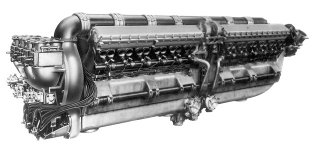
The 1,000 hp (746 kW), 16-cylinder Napier Cub. Below the propeller gear reduction are the two duplex carburetors with an induction pipe leading to each cylinder bank.
What Napier had envisioned, and the Air Ministry purchased, was a large power plant of 1,000 hp (746 kW)—enough power for one engine to propel a large bomber aircraft. The engine was given the Napier designation E66 but was referred to as the Cub. Despite its diminutive name, the Cub was a much larger engine than the Lion. The Napier Cub was unlike any engine before or since.
The Napier Cub was a liquid-cooled, 16-cylinder engine with four banks of four cylinders arranged in an X configuration on an aluminum crankcase. The banks were not equally spaced: the angle between the top banks was 52.5 degrees; the banks on either side were angled at 90 degrees; and the angle between the bottom banks was 127.5 degrees. Reportedly, the engine was so arranged to relieve stress on the crankshaft and to ease the engine’s installation in aircraft.
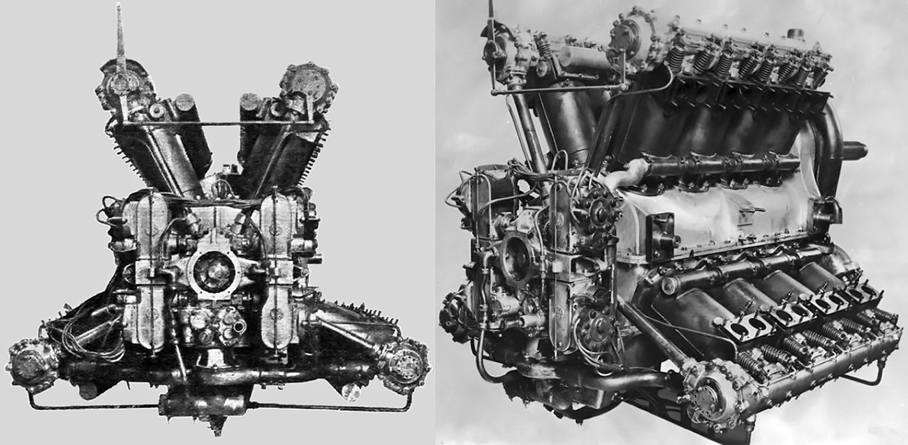
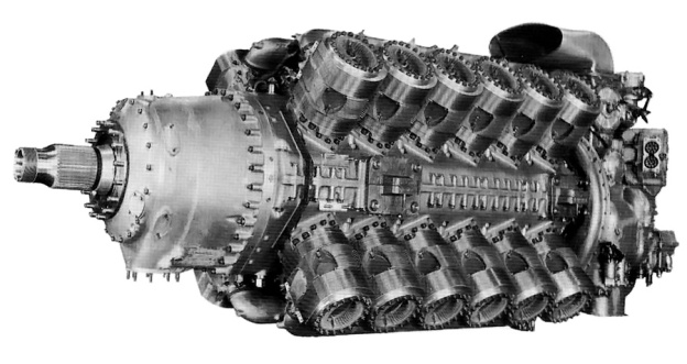
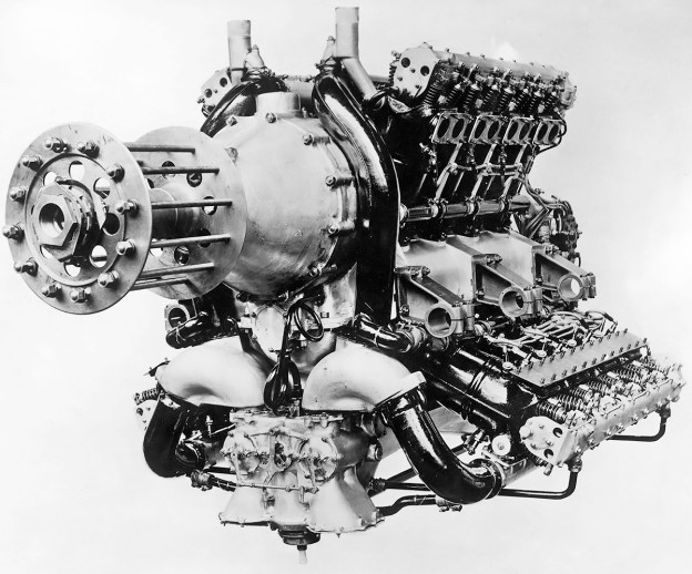
The Napier Cub was the first aircraft engine to exceed 1,000 hp (746 kW). These rear views illustrate the cylinder bank angles, the four magnetos on the back of the engine, the housings for the camshaft drive, and the exposed valves.
The Cub used individual steel cylinders of a 6.25 in (158.75 mm) bore and 7.5 in (190.5 mm) stroke and were encased in separate welded-steel water jackets. The engine displaced 3,682 cu in (60.3 L). The Cub’s compression ratio was 5.3 to 1. The engine was 57 in (1.45 m) wide, 64.25 in (1.63 m) tall, 71.8125 in (1.9 m) long, and weighed 2,450 lb (1,111 kg).
Each of the Cub’s four connecting rods consisted of one master rod and three articulated rods. The pistons were aluminum and had two compression and two oil-scrapper rings. Each cylinder bank had a single overhead camshaft that was driven via a vertical shaft. The vertical shafts were at the rear of the engine and driven from the crankshaft. The overhead camshaft actuated four exposed valves per cylinder. The Cub had a 0.49 propeller gear reduction through the use of spur gears that raised the propeller shaft. The propeller shaft’s bearing arrangement allowed the engine to be used in either a tractor or pusher configuration.
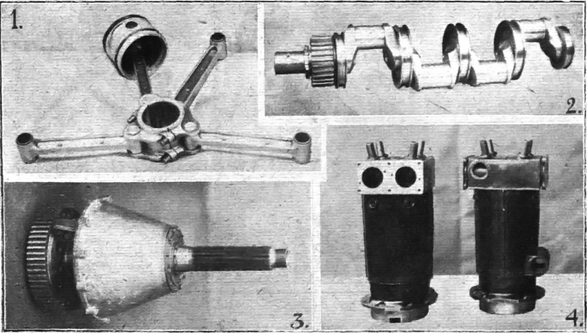
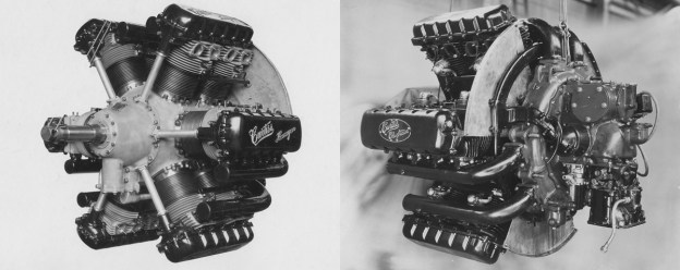
Various parts of the Napier Cub: 1) connecting rod assembly with one articulated rod attached to the bearing cap; 2) four-throw crankshaft with roller bearings and spur reduction gear; 3) propeller shaft with large spur reduction gear; 4) two of the Cub’s cylinders with the valve ports visible on the left cylinder and the water-cooling ports visible on the right cylinder.
Dual ignition was provided by four magnetos geared off the rear of the engine. The single water circulation pump was located at the lower rear of the engine, was driven at 1.5 times camshaft speed, and had one outlet to supply each cylinder bank. Two duplex carburetors were located under the gear reduction at the front of the engine. Each carburetor fed two manifolds: one for an upper cylinder bank and the other for a lower bank.
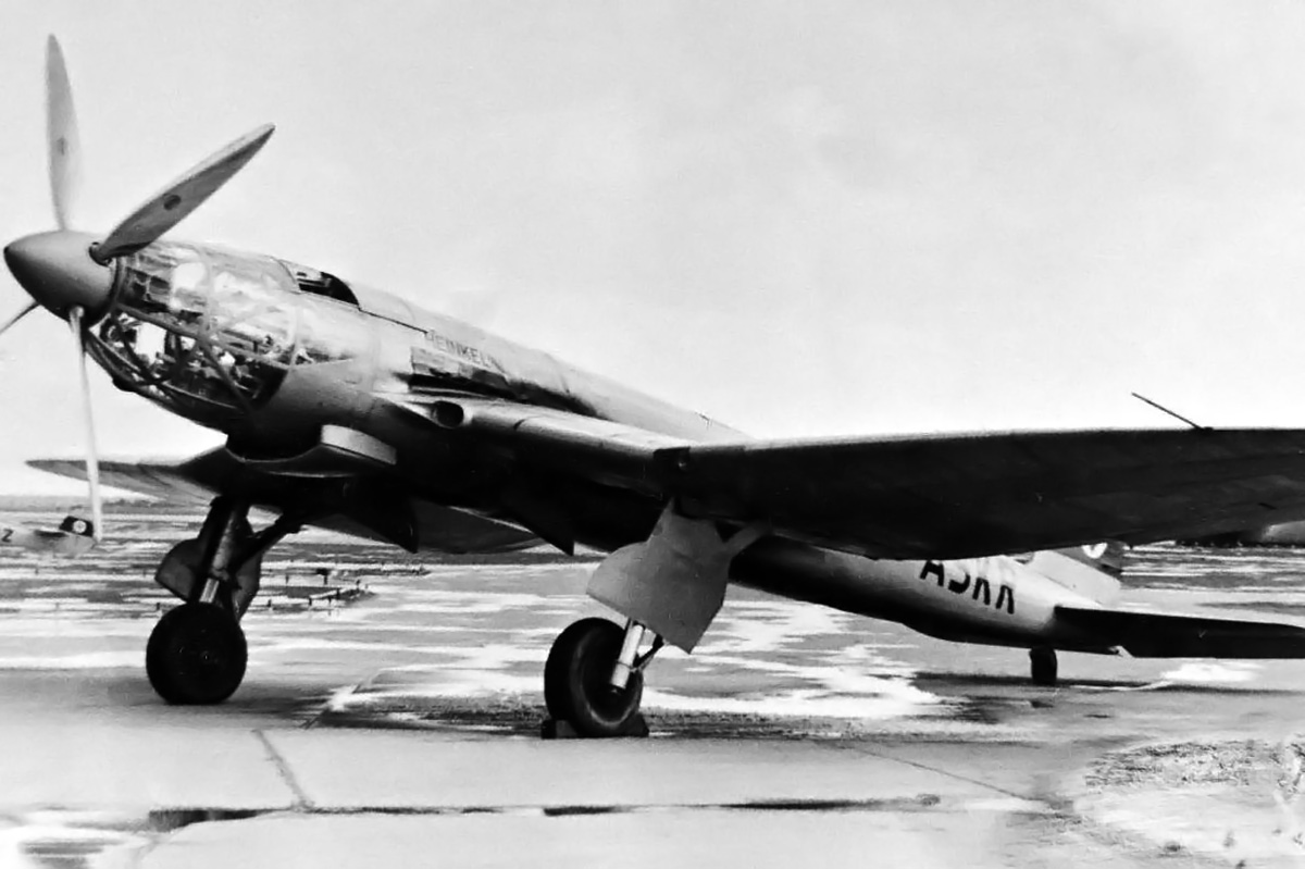
The Napier Cub was first run in late 1920. It was the first aircraft engine to surpass the 1,000 hp (746 kW) mark, achieving 1,057 hp (788 kW) at 1,900 rpm during an early test. The second Cub engine built was first run in early 1922. That same year, the Cub was installed in a modified Avro 549 Aldershot I (J6852, the first prototype) and re-designated Aldershot II. The Aldershot was a long-range, heavy bomber bi-plane. It had a 68 ft (20.7m) wingspan, was 45 ft (13.7 m) long, and weighed around 6,200 lb (2,812 kg). The Cub-powered Aldershot II first flew on 15 December 1922, piloted by Bert Hinkler. The Aldershot II continued to fly for about four years before the Napier Cub was removed and another test engine (an 800 hp / 597 kW Beardmore Typhoon) was installed.
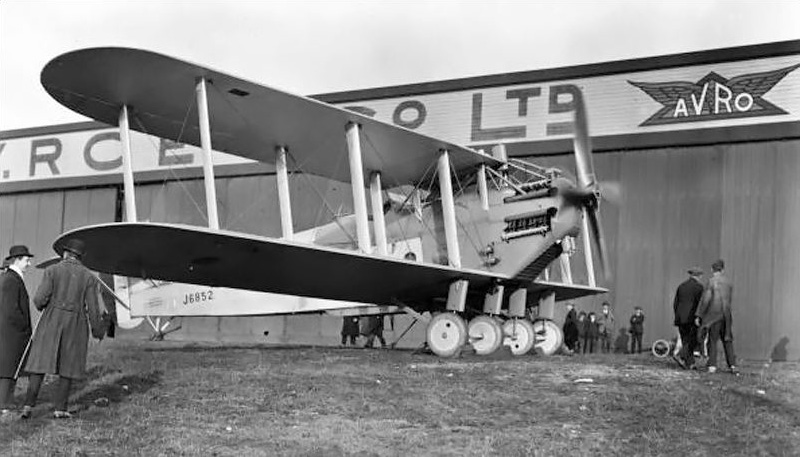
Napier Cub-powered Avro Aldershot II (J6852). This was the first Aldershot prototype, originally powered by a 650 hp (485 kW) Rolls-Royce Condor V-12 engine. To support the Cub, the aircraft was strengthened and had its main gear doubled to four wheels. After two years of Cub-power, the aircraft was re-engined with an 800 hp (597 kW) Beardmore Typhoon.
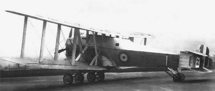
A Napier Cub was also installed in both of the two Blackburn T.4 Cubaroos built. The Cubaroo was a long-range coastal defense bi-plane capable of carrying a 21-in (.533 m) torpedo or equivalent bomb load of 2,000 lb (907 kg). The aircraft had an 88 ft (26.8 m) wingspan, was 54 ft (16.5 m) long, and weighed 9,632 lb (4,396 kg) empty and 19,020 lb (8,709 kg) fully loaded. The Cubaroo was possibly the largest single-engine aircraft in its day. The first Cubaroo (N166) took to the air in the summer of 1924, piloted by P.W.S. ‘George’ Bulman. The aircraft was delivered to Martlesham Heath for flight trials in October 1924. Several engine failures were noted as well as a tendency for the engine to overheat during a high-power climb.
The second Cubaroo (N167) had a revised radiator and first flew in early 1925. Both Cubaroo aircraft were flown in various aviation displays and used for testing. N166 was damaged beyond repair in a landing accident on July 16, 1926. N167 continued to fly with Cub-power until 1927, when it was re-engined to test the 1,100 hp (820 kW) Beardmore Simoon.
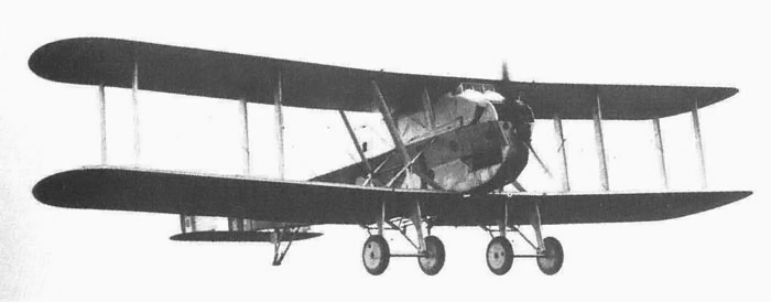
The first Blackburn Cubaroo (N166) in flight. The 1,000 hp (746 kW) Cub seemed to be quite adequate for the large aircraft.
Another aircraft designed to use the Napier Cub was the Avro 556. With a wingspan over 95 ft (30 m), this aircraft was even larger than the Cubaroo, although intended for the same purpose of carrying a 21-in (.533 m) torpedo. This aircraft was never built; instead, the basic design was used for the twin Rolls-Royce Condor-powered Avro 557 Ava.
By June 1925, the concept of a single, large aircraft engine powering a very large aircraft fell to the wayside in favor of multiple engines, which gave some degree of enhanced safety. The Air Ministry lost its interest in the Napier Cub, and the world’s first 1,000 hp (746 kW) aircraft engine faded to obscurity.
The second Blackburn Cubaroo (N167) with the revised radiator to cool the Napier Cub.
Sources:
– Aerosphere 1939 by Glenn Angle (1940)
– Men and Machines by Wilson and Reader (1958)
– By Precision Into Power by Alan Vessey (2007)
– Avro Aircraft since 1908 by A J Jackson (1965/1990)
– Blackburn Aircraft since 1909 by A J Jackson (1968/1989)
– The British Bomber since 1914 by Francis Mason (1994)
– British Flight Testing: Martlesham Heath 1920-1939 by Tim Mason (1993)
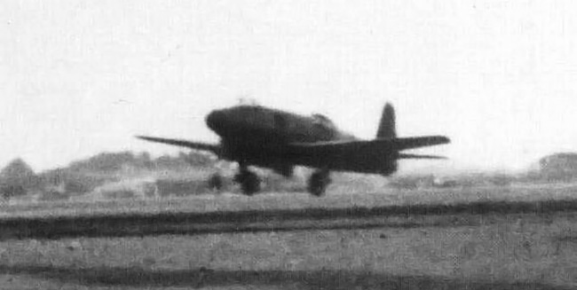
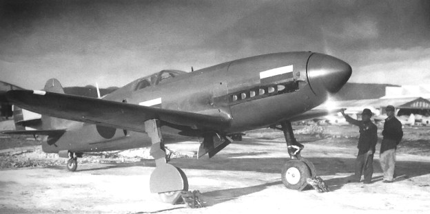
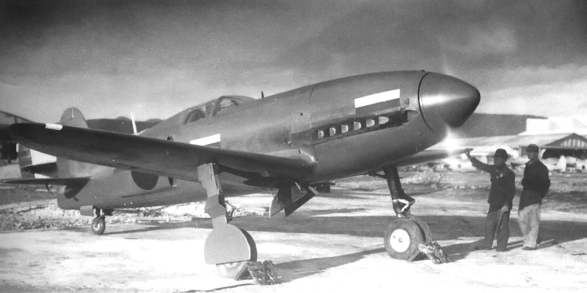
![The standard image of the Yokosuka R2Y1 Keiun. Speculation suggests the first scoop on the side of the aircraft provided cooling air for the engine's internal exhaust baffling, the second, larger scoop provided induction air for the normally aspirated Aichi [Ha-70] engine installed in the prototype, and the final two ports were for the engine's exhaust.](https://oldmachinepress.com/wp-content/uploads/2012/12/yokosuka-r2y1-keiun.jpg)