Monthly Archives: November 2012

Rolls-Royce Exe (Boreas) and Pennine Aircraft Engines

By William Pearce

Arthur Rowledge was one of the most prolific designers of piston aircraft engine in history. In 1913 he joined Napier & Son where he designed the firm’s first aircraft engine, the Lion, in 1917. This engine went on to achieve great success and was even used during World War II, but Rowledge moved on to Rolls-Royce (R-R) in 1921. While at R-R, Rowledge was very involved with the Condor III, Kestrel, “R” Schneider, and Merlin engines. Rowledge also designed the air-cooled and sleeve-valve Exe and Pennine engines. These two engines were quite a departure from standard R-R practice and never made it to production status.

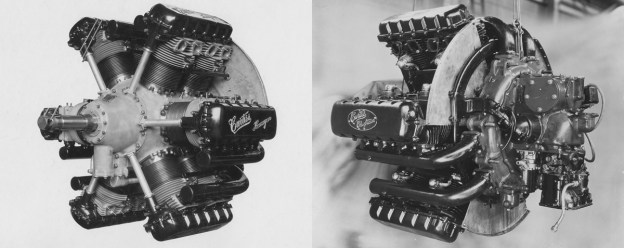
Side view of the Rolls-Royce Exe engine. The cylinder baffling in the image is of a simple construction when compare to the other engine image below. It appears to be the same baffling as seen on the engine installed in the Battle.

In the 1930s Rowledge became seriously ill and took a leave from R-R. During his recovery, R-R decided not to bring him back to the main engine development programs but to give him complete control of designing a new engine. This new engine was based on a 1,000 hp (746 kW) requirement from the Fleet Air Arm for shipboard aircraft use where air-cooling was preferred. The new engine was sanctioned in February 1935 and originally called Boreas, but the name was later changed to Exe.

The Exe engine had four banks of six cylinders in an X configuration. Each bank was 90 degrees from the next. The cylinders had a 4.225 in (107.3 mm) bore and 4.0 in (101.6 mm) stroke, for a total displacement of 1,346 cu in (22.1 L). The Exe had a two-speed, single-stage supercharger, and the compression ratio was 8 to 1. The engine weighed 1,530 lb (694 kg). The two spark plugs for each cylinder were fired by coil ignition rather than standard magnetos. A 0.358 gear reduction to the propeller was achieved through spur gears; their arrangement elevated the propeller shaft centerline above the crankshaft.

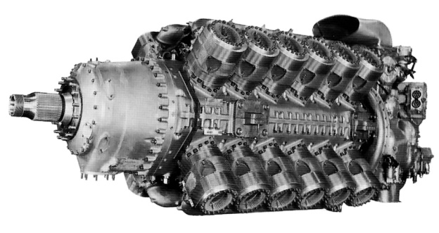
Clear view of the Rolls-Royce Exe and the baffling around each cylinder to direct air for proper cooling. The baffling appears to be an updated version compared to the image above. Also note how the spur reduction gear has elevated the propeller thrust line.

The sleeve-valves, undoubtedly inspired by Harry Ricardo, followed the established Burt-McCollum/Bristol practice. Each cylinder barrel had three intake ports and two exhaust ports. The sleeve itself had only four ports, one was shared as an intake and exhaust port. The drive cranks for the sleeve valves were driven via spiral gears from a shaft that ran along each side of the engine. A.A. Rubbra states that these shafts were driven from the propeller gear reduction. The single sleeve for each cylinder was sealed by the use of a junk head. The entire system proved to be quite reliable.

The connecting rods consisted of one master rod and three articulating rods. The big end was essentially a square with the master rod extending from one corner and the three articulated rods attached to each of the other corners. The big end was split and bolted together around the crankshaft via four bolts.

A specialized pressure air-cooling method was used. Cooling air entered the engine cowling below the spinner. The air was then fed into the upper and lower Vees. Baffles attached to the individual cylinders caught and directed the air through the cylinder’s cooling fins. The air passed from the upper and lower Vees into the side Vees and exited toward the rear of the engine cowling. Reportedly, the arrangement worked very well with minimal drag and no cooling issues. Induction manifolds delivered the air/fuel mixture to the cylinders through the top and bottom Vees. Exhaust from the cylinders was collected in manifolds on the side Vees.

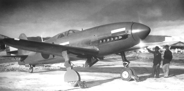
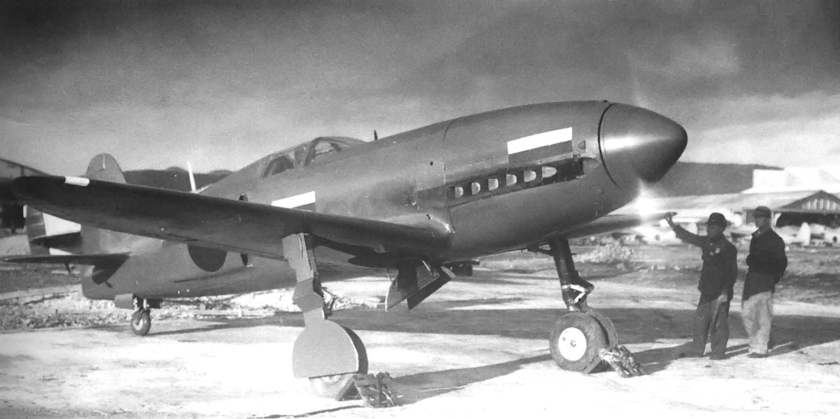
A great image of the Exe installed in the Battle with the cowling removed. Note early version of the cylinder baffling.

The Exe was originally rated at 920 hp (686 kW) at 3,800 rpm. The engine was first run in September 1936, and it had completed a 40-hour development test by the end of 1937. The Exe first took to the air in a modified Fairey Battle (K9222) on 30 November 1938. This particular aircraft was owned by R-R and was modified at the R-R Flight Development Establishment at Hucknell. Exe engine development continued with very little trouble; however, the engine did suffer from excessive oil consumption. Ultimately the engine’s output was increased to 1,200 hp (895 kW) at 4,200 rpm, and continued development to 1,500 hp (1,119 kW) was planned.

A liquid-cooled version of the engine was also studied. A four cylinder test engine representing an X configuration was run in 1938. Each cylinder of the test engine had its own steel water jacket. The program progressed, and a complete liquid-cooled X-24 engine was built; this engine featured normal cast aluminum cylinder blocks with integral water jackets. Reportedly, this engine was run and tested but never flew.

Rolls-Royce Exe installed in Fairey Battle K9222. Note the cooling air intake under the spinner and exit by the exhaust stacks. The Exe-powered Battle continued to fly long after the engine was cancelled.

The Exe was originally intended to power the Fairey Barracuda torpedo-bomber and the production Fairey F.C.1 four-engine transport. With the start of World War II, top priority was given to developing and producing Merlin and Griffon engines. Ernest Hives, R-R General Works Manager, estimated that building 275 Exe engines would be the production equivalent of 1,200 Merlins. At his request, work on the Exe program was suspended in September 1939 and stopped completely by 1941. Development was also discontinued on the liquid-cooled engine. The Barracuda was switched to Merlin power, and the F.C.1 was never built.

As an indicator of the engine’s sound design and reliability, the Exe-powered Battle continued to fly until 1943, long after the Exe program was cancelled. In addition, R-R’s Exe-powered Battle flew at higher speeds than the standard Merlin-powered Battles.

The encouraging results from the Exe compelled a small design team to continue work on the air-cooled, sleeve-valve engine concept. Around June 1943, design work was accepted on what was essentially an enlarged Exe. The new engine project was known as the Pennine and was headed by Dr. Sprinto Viale.

Rolls-Royce Pennine engine shown without any exhaust stacks or spark plug leads. The cylinders look very similar to those used by Bristol. The ring of studs around the propeller shaft is where the annular cooling fan would attach.

The Pennine had the same layout as the Exe, with the exception of the propeller gear reduction. Rather than spur gears, which would raise the propeller shaft as on the Exe, the Pennine used epicyclic (planetary) gears that allowed the propeller shaft to be in-line with the crankshaft. A propeller gear reduction of .3 or .4 was used. In addition, an annular cooling fan was driven from the gear reduction at 1.03 times crankshaft speed. Illustrations done by Lyndon Jones show the drive shafts for the sleeve valves geared to the rear of the crankshaft rather than to the gear reduction. It is possible this deviation from the Exe’s design was a result of the aforementioned changes to the gear reduction. Design work on the engine was completed by September 1944.

Another change from the Exe that can be seen in the Jones illustration was the connecting rod arrangement. Rather than having a split big end, the Pennine utilized a one piece master connecting rod with three articulated rods. The crankshaft’s crankpins were bolted together through the one piece master rods.

The Pennine engine had a 5.4 in (137.2 mm) bore and 5.08 in (129 mm) stroke, giving a total displacement of 2,792 cu in (45.8 L); this was over twice the displacement of the Exe. With a dry weight of 2,850 lb (1,293 kg), the Pennine was 106 in (2.69 m) long, 37.5 in (.95 m) tall, and 39 in (.99 m) wide. The engine was equipped with a single stage, two speed supercharger that provided 12 psi (.83 bar) of boost at takeoff and combat power settings. The Pennine developed 2,750 hp (2,051 kW) at 3,500 rpm at sea-level and up to 2,800 hp (2,088 kW) under combat settings. A reliable 3,000 hp (2,237 kW) was thought to be easily obtainable with further development.

Pennine sectional view from Sectioned Drawings of Piston Aero Engines* by Lyndon Jones. Note the annular fan and sleeve valve drives.

Only one or two Pennine test engines were built; the first was finished on 31 December 1944. The engine was run on teststands during 1945, and an engine cowling was developed to maximize the efficiently of the pressurized air-cooling. While the engine ran well, the end of piston-powered military aircraft and civil airliners was on the horizon, with piston engines being supplanted by jet engines. Possible applications for the Pennine engine were the Fairey Spearfish torpedo bomber and the Miles X.11 airliner. Ultimately, the Spearfish was powered by a Bristol Centaurus. The Miles aircraft lost out to the Bristol Brabazon and was never built. Development of the Pennine was stopped in mid to late 1945.

A further engine study was made where two 16-cylinder power sections (using Pennine cylinders) of an X configuration were attached to a common crankcase. This arrangement made an X-32 engine and was known as the Snowden. A shaft from the midsection, between the two X-16 power sections, was to travel forward along the top and bottom Vees of the engine to a gear reduction that drove half of a coaxial contra-rotating propeller unit. This engine would have displaced 3,723 cu in (61.0 L) and produced 4,000 hp (2,983 kW). Some testing was done, but a complete engine was never built.

Rear view of the Pennine engine and cowling. Note the baffling for each individual cylinder and the circular front of the cowling for the annular cooling fan..

Sources:
Rolls-Royce Piston Aero Engines — A Designer Remembers by A.A. Rubbra (1990)*
Rolls-Royce Aero Engines by Bill Gunston (1989)
British Piston Aero Engines and their Aircraft by Alec Lumsden (1994/2003)
Major Piston Engines of World War II by Victor Bingham (1998/2001)
Allied Aircraft Piston Engines of World War II by Graham White (1995)
Sectioned Drawings of Piston Aero Engines by Lyndon Jones (1995)*
Rolls-Royce — Hives, the Quiet Tiger by Alec Harvey-Bailey (1985)
http://www.secretprojects.co.uk/forum/index.php?topic=5375.0
– “Rolls-Royce and the Sleeve Valve” by Phil Kennedy, New Zealand Rolls-Royce & Bentley Club Inc, Issue 07-3 2007 (pdf)
http://en.wikipedia.org/wiki/Arthur_Rowledge

*Rolls-Royce Heritage Trust books that are currently in print and available from the Rolls-Royce Heritage Trust site.

Fokker F.XX Zilvermeeuw Transport

By William Pearce

In the never-ending quest for speed, KLM (Royal Dutch Airlines) asked the Fokker Aircraft Corporation to design an aircraft for its East Indies route that could fly some 35 mph (56 km/h) faster than the Fokker F.XVIII then in service. Fokker’s response was a trimotor design that could accommodate 12 passengers and three crew members. The new aircraft, the Fokker F.XX Zilvermeeuw (Herring Gull), was the last wooden aircraft and last trimotor built by Fokker. However, it was the first Fokker-built aircraft with retractable landing gear.

The Fokker F.XX: the pinnacle of the Fokker trimotors.

The Fokker F.XX was revealed on 20 December 1932. The aircraft was built under the direction of Marius Beeling and featured a fabric covered fuselage of steel tube construction. The fuselage used an elliptical cross section, another design-first for Fokker, who had used rectangular fuselages on their earlier aircraft. The F.XX’s high-wing had a wooden structure and was plywood covered. The plywood skin was omitted from the lower wing section running through the cabin so that more headroom was available for the passengers.

The aircraft was originally powered by three 650 hp (485 kW), nine-cylinder, air-cooled Wright Cyclone R-1820-F engines, all housed in NACA cowlings. One engine was in the nose of the aircraft, and the others were each in a nacelle suspended under each wing by struts. Later, KLM replaced the engines with more powerful 690 hp (515 kW) Wright Cyclone R-1820-F.2 engines. Metal, two-blade, ground-adjustable propellers were initially used. However, when the uprated engines were installed, metal Hamilton Standard propellers that were adjustable in-flight were used.

The Fokker F.XX under constructions in 1933.

The Fokker F.XX was 54.8 ft (16.7 m) long and had a span of 84.3 ft (25.7 m). The aircraft weighed 11,795 lb (5,350 kg) empty and 19,510 lb (8,850 kg) loaded. Range with full fuel was 1,056 mi (1,700 km), and range with full payload was 400 mi (645 km). The aircraft’s service ceiling was 21,650 ft (6,600 m). Maximum speed of the F.XX was 190 mph (305 km/h), and cruise speed was 155 mph (250 km/h).

The F.XX carried the Dutch registration PH-AIZ and made its first flight on 3 June 1933, piloted by Emil Meineche. For this first flight, the engine cowlings were omitted and the undercarriage was not retracted. During a test on 29 June 1933, it was found that heavy aileron vibration occurred as speed was increased. This phenomenon was solved by adding 70 lb (32 kg) of balance weights to the ailerons. Flight testing resumed on 11 August 1933.

The F.XX probably undergoing early flight tests with the large gear doors still installed and short engine nacelles.

It was also discovered that when the landing gear was deployed, the large door in front of each main wheel caused turbulence that resulted in severe vibrations of the tail section. The doors were reduced in size, but the problem persisted. Eventually, the doors were removed altogether. During the flight test program, the engine nacelles were lengthened to reduce drag. The flight test program, the airworthiness trials, and the acceptance flights were completed over the course of four months, encompassing 62 flights that totaled 37 hours in the air.

On 18 December 1933, the Fokker F.XX made its KLM debut on a special Christmas mail flight to the East Indies. The objective was to fly as fast as possible to the Dutch colonies in competition with another aircraft, the Pander S.4 Postjager, to inaugurate a special mail service.

Inflight image of the Fokker F.XX showing its graceful lines.

The Pander Postjager had departed earlier but was stranded in Italy because of an engine failure, leaving the Fokker F.XX poised to win the competition. However, engine trouble was experienced during a warm-up, and the F.XX was grounded. Work to repair the F.XX would take too much time, and KLM quickly prepared a Fokker F.XVIII for the Christmas flight. It was a disastrous public failure for the new F.XX, one from which it never fully recovered.

Although the F.XX was a more advanced design than earlier Fokker aircraft, the eminent arrival of twin-engine, low-wing, metal aircraft (like the Douglas DC-2) rendered it obsolete. In addition, the negativity surrounding the failed Christmas flight meant that there would no production contract for the Fokker F.XX. Quietly and shrewdly, Fokker Aircraft Corporation obtained manufacturing rights for the DC-2.

The F.XX with the gear doors removed and lengthened engine nacelles.

However, the F.XX’s reputation was boosted when KLM began using the aircraft on a fast London-Amsterdam-Berlin service starting 1 March 1934. On the Amsterdam-Berlin leg of the flight, the aircraft achieved an impressive average speed of 157 mph (253 km/h). Also in 1934, the F.XX flew 1,535 hours; this was nearly double KLM’s 850 flight hour average with the F.XVIII.

The F.XX was in service with KLM for only a few years. In September 1936, the aircraft was sold to Alain Pilain of France and registered as F-APEZ. Mr. Pilain represented the fictitious airline Air Tropique, which was a cover for another organization: the Société Française de Transports Aériens (SFTA). SFTA was a purchasing agent for the Spanish Republicans disguised as a French air transport service.

The Fokker F.XX in service with the Spanish Republicans and with a camouflage paint scheme as seen at Le Bourget, France in 1937.

SFTA flew the aircraft to Spain in October 1936, where it carried the governmental registration EC-45-E and was used in the Spanish Civil War. The F.XX was painted in a camouflaged scheme and used to transport various cargoes (including gold bullion and jewelry) between Spain and France.

It was not a very popular aircraft, especially after one of its Wright engines was replaced with a Walter-built Mercury engine from a Letov S-231 fighter, and at least one other engine was replaced with a Shvetsov M-25 engine from Polikarpov I-16 fighter. The engine changes resulted in a vicious yaw on takeoff. The F.XX served with the Republicans until early February 1938 when, piloted by Eduardo Soriano, it was destroyed in a crash near Barcelona at Prat de Llobregat Airport.

The following is a video of the Fokker F.XX Zilvermeeuw filmed in 1933 and uploaded by BeeldenGeluid.


Sources:
– “The Fokker F.XX,” Flight (5 October 1933)
– “Fokker’s Trimotors Go To War,” Air Enthusiast, No. 13 August–November 1980 by Gerald Howson
Jane’s All the World’s Aircraft 1934 by C.G. Grey (1934)
Aircraft of the Spanish Civil War 1936-1939 by Gerald Howson (1990)
Fokker: Aircraft Builders to the World by Thijs Postma (1979/1980)
http://www.dutch-aviation.nl/index5/Civil/index5-2%20F20.html

Curtiss H-1640 Chieftain Aircraft Engine

By William Pearce

In April 1926 the Curtiss Aeroplane and Motor Company initiated a design study for a 600 hp (447 kW), air-cooled aircraft engine. The engine was to have minimal frontal area while keeping its length as short as possible. Configurations that were considered but discarded were a 9-cylinder single-row radial, a 14-cylinder two-row radial, a 12-cylinder Vee, and a 16-cylinder X. The selected design was a rather unusual 12-cylinder engine that Curtiss referred to as a “hexagon” configuration. This engine was built as the Curtiss H-1640 Chieftain.

The Curtiss H-1640 Chieftain “hexagon” or “inline-radial” engine. The image on the left was taken in 1927; note “Curtiss Hexagon” is written on the valve covers. In front of each cylinder pair is the housing for the vertical shaft that drove the overhead camshafts. The image on the right was taken in 1932 and shows a more refined engine with “Curtiss Chieftain” written on the valve covers. Note the additional cooling fins surrounding the spark plugs. In both images, the baffle at the rear of each exhaust Vee forced cooling air into the intake Vee.

The Curtiss H-1640 was designed by Arthur Leak and Arthur Nutt. The Chieftain’s “hexagon” design was a combination of a radial and Vee engine. The intent was to combine the strengths of both engine configurations: the light and short features of a conventional radial with the narrow and high rpm (for the time) of a conventional Vee engine.

The Chieftain was arranged as if it were a 12-cylinder Vee engine cut into three sections, each being a four-cylinder Vee. The Vee engine sections were then positioned in a radial form 120 degrees apart (each cylinder bank being 60 degrees apart). The end result was a two-row, twelve-cylinder, inline radial engine. The H-1640 resembled a conventional radial engine except that the second cylinder row was directly behind the first.

An engine installation comparison of the air cooled Chieftain-powered XO-18 Falcon at left and a liquid-cooled D-12-powered Falcon at right. Note that while the Chieftain is a wider engine, it blends well with the fuselage and is shorter and not as tall as the Curtiss D-12.

Each four-cylinder Vee section had the cylinder exhaust ports on the inside of the Vee and the intake ports on the outside. Each inline cylinder pair had its own intake runner and dual-overhead camshafts that were enclosed in a common valve cover. The camshafts were driven via a single vertical shaft from the front of the engine. There were four valves per cylinder.

Cooling air was directed through each four-cylinder section’s exhaust Vee; here it met a baffle fitted to the rear of the engine and attached to the cowling. This baffle deflected the air and forced it to flow between the inline cylinders and behind the rear cylinder. The air then flowed into the intake Vee that was blocked off at the front. The air exited the cowling via louvers over the intake Vee.

The Curtiss O-1B Falcon that was redesignated XO-18 while it served as the test-bed for the Chieftain engine. Note the exposed valve covers and the exhaust stacks protruding through the engine cowling.

The pistons were aluminum and operated in steel cylinder barrels that were screwed and shrunk into cast aluminum cylinders with integral cooling fins. From U.S. patent 1,962,246 filed by Leak in 1931, it appears that the Chieftain’s connecting rods consisted of two halves that were bolted together. Each half was made up of one master rod and two articulating rods.

The H-1640 Chieftain had a bore of 5.625 in (143 mm) and a stroke of 5.5 in (140 mm), giving a total displacement of 1,640 cu in (26.9 L). The engine’s maximum diameter was 45.25 in (1.15 m). However, a special cowling was used, cut to allow the valve covers and exhaust stacks to protrude through, reducing the diameter of the cowling to 39 in (0.99 m). The engine was 52.3 in (1.33 m) long and weighed 900 lb (408 kg). The Chieftain had a 5.2 to 1 compression ratio and was rated at 600 hp (447 kW) at 2,200 rpm but developed 615 hp (459 kW). When the engine was pressed to 2,330 rpm, it produced 653 hp (487 kW). It was equipped with a centrifugal-type supercharger that allowed the engine to maintain sea-level power up to 12,000 ft (3,658 m). All Chieftain engines built were direct drive but geared versions had been planned. In addition, some design work on a four-row, 24-cylinder version of 1,200 hp (895 kW) had been done.

Side view of the Thomas-Morse XP-13 Viper with the Curtiss Chieftain engine and revised cowl. Not the louvers for the cooling air to exit the cowling.

Because the engine had an even number of cylinders per each row, a unique firing order was developed that alternated between the front and rear rows. When the engine was viewed from the rear, the cylinders were numbered starting with the cylinder bank at the 9 o’clock position and proceeding clockwise around the engine. The rear cylinder row had odd numbers, and the front cylinder row was even so that the rear cylinder of the cylinder bank at 9 o’clock was number 1 and the front was number 2. The firing order was initially 1, 10, 5, 7, 4, 11, 8, 3, 12, 2, 9, 6 but was later changed to 1, 10, 5, 2, 9, 11, 8, 3, 12, 7, 4, 6 in an effort to smooth out the engine.

The H-1640 Chieftain was first run in 1927 and flown in a modified Curtiss O-1B Falcon, redesignated XO-18, in April 1928. The Chieftain-powered test-bed aircraft was found to out-climb and have a higher ceiling than the standard liquid-cooled Curtiss D-12-powered Falcon. In addition, the top-speed of the two aircraft was the same, which was unheard of for that time period when liquid-cooled aircraft were faster than their air-cooled counterparts. However, the engine suffered cooling issues, and the aircraft was modified back to an O-1B in July 1930.

A comparison of the original cowling on the XP-13 at left and the updated cowling at right. The front of the cowling has been extended and angled out. The block-off plates in between the openings have been angled to funnel air into the enlarged openings.

Thomas-Morse also responded to the Army’s interest in using the Curtiss H-1640. The company’s Viper fighter prototype was built to use the Chieftain engine. This aircraft was tested at Wright Field in June 1929 and given the designation XP-13. Engine overheating was encountered, and a revised cowling was tried in an effort to provide adequate cooling for the H-1640. The new cowling had enlarged openings, and the blocked off sections were angled to force more air into the openings. However, over-heating persisted. The XP-13 was tested until September 1930, when a Pratt & Whitney R-1340C engine was installed and the aircraft redesignated XP-13A. Even though this engine was not as powerful, it was lighter and did not suffer the cooling issues present with the Chieftain. The XP-13A was found to be 15 mph (24 km/h) faster than the Chieftain-powered XP-13. Curtiss had planned to produce the Viper under the designation XP-14, but the H-1640 engine was lacking support so no aircraft were built.

Another Chieftain was installed in the Navy’s second Curtiss XF8C-1 prototype in 1930. The H-1640-powered aircraft was known as the Curtiss XOC3. It too suffered from engine over-heating. The Chieftain engine remained installed in the XOC3 until the aircraft was removed from the Navy’s inventory in April 1932.

Detail view of the revised cowling on the Chieftain-powered Thomas-Morse XP-13. The image on the left illustrates the angle of the block-off plates. Note the six, instead of eight, exhaust stacks of the upper cylinders. The last two stacks are combined and exit from a single stack aft of the cowling.

In October 1928, the Army ordered three Curtiss P-6 Hawk aircraft to be powered by the H-1640 engine and designated them XP-11. However, shortly after the order was placed, the engine’s cooling trouble became known and the engine’s development ceased. The aircraft were never built with the Chieftain engine.

A total of eight H-1640 engines were made with six going to the Air Corps and two to the Navy. While the Chieftain’s design may have been problematic, the event that directly led to its lack of support and ultimate abandonment was the merger of Curtiss Aeroplane and Motor Company with Wright Aeronautical in July 1929. After the merger, the liquid-cooled engines were provided by Curtiss and the air-cooled engines from Wright. There was no longer a need for the Chieftain, an air-cooled engine of rather dubious design. However, the concept of a hexagonal engine would be revisited with the Wright H-2120, and other hexagonal engines include the SNCM 137, the Junkers Jumo 222, and the Dobrynin series of aircraft engines..

Reportedly, at least one Curtiss H-1640 Chieftain survives and is in storage at the National Air and Space Museum’s Garber Facility in Silver Hill, Maryland.

The second Curtiss XF8C-1 re-engined with the H-1640 Chieftain and redesignated XOC3.

Sources:
Modern Aviation Engines, Volume 2 by Victor Page (1929)
– “The Curtiss ‘Chieftain’ Engine,” Flight by Erik Hildeshim (14 June 1928)
Dyke’s Aircraft Engine Instructor by A.L. Dyke (1929)
Aerosphere 1939 by Glenn Angle (1940)
Curtiss Aircraft 1907-1947 by Peter Bowers (1979/1987)
American Combat Planes of the 20th Century by Ray Wagner (2004)
Fighters of the United States Air Force by Dorr and Donald (1990)
General Dynamics Aircraft and their Predecessors by John Wegg (1990)

Kawasaki Ki-78 (KEN III)

By William Pearce

In the 1930s, Japanese aviation began to make strides toward closing the technological gap with the Western World. In 1938, the Aeronautical Research Institute of the University of Tokyo, led by Shoroku Wada, began a high-speed aircraft research program. Gathering data on high-speed flight was the primary objective, but it was felt that an attempt on the 3 km absolute world speed record was an obtainable goal.

The nearly complete and unpainted high-speed research aircraft, the Kawasaki Ki-78. Note the radiator housing on the fuselage side.

The aircraft project was known as KEN III (for Kensan III or Research III) and incorporated numerous advanced features new to Japanese aircraft. Approval was given for the aircraft’s development and a full-scale wooden mockup was finished in May 1941. Because of the outbreak of World War II, the project was taken over by the Imperial Japanese Army and designated Ki-78. A production contract for two prototypes was awarded to Kawasaki, under the direction of Isamu Imashi. Construction of the first prototype began in September 1941 at Kawasaki’s plant at Gifu Air Field.

The Ki-78 was an all-metal, low wing monoplane of conventional layout. The small streamlined fuselage was made as narrow as possible and was 26 ft 7 in (8.1 m) long. The wings possessed a laminar flow airfoil with a span of 26 ft 3 in (8 m) and an area of 118.4 sq ft (11 sq m). To reduce landing speed and improve low-speed handling, the wings incorporated drooping ailerons along with a combination of Fowler and split flaps, which was a first for a Japanese aircraft. When the Fowler flaps were deployed, the split flaps opened simultaneously to a similar extent. When the flaps were fully deployed, the ailerons automatically drooped down 10 degrees.

Factory fresh and unpainted view of the Ki-78. The aircraft is missing its outer gear doors and there is no horn-balance on the elevator.

Power for the Ki-78 was provided by an imported Daimler-Benz DB 601A inverted V-12 engine driving a three-blade metal propeller. The engine was not a Kawasaki Ha-40, a licensed copy of the DB 601. The DB 601 had a 5.91 in (150 mm) bore and 6.30 in stroke (160 mm), giving a total displacement of 2,070 cu in (33.9 L). It produced 1,175 hp (876 kW) at 2,500 rpm. The engine was modified by Kawasaki with the addition of a water-methanol injection system (another Japanese first) to boot the power output to 1,550 hp (1,156 kW) for short periods. The Ki-78 carried 66 gal (250 L) of fuel and 16 gal (60 L) of water-methanol.

The freshly-painted Ki-78 running-up its DB 601A engine. Note the hinge in the outer gear door to account for extension of the gear strut.

The freshly-painted Ki-78 running-up its DB 601A engine. Note the hinge in the outer gear door to account for extension of the gear strut.

Engine cooling was provided by two radiators: one mounted on each side of the rear fuselage. The radiators had a wide air inlet protruding slightly out from the fuselage. Airflow through each radiator was controlled by an actuated exit door. In addition, within the fuselage a small 60 hp (45 kW) turbine drove a fan to further assist cooling. The aircraft stood 10 ft 7/8 in (3.07 m) tall and weighed 4,255 lb (1,930 kg) empty.

The Ki-78 first flew on 26 December 1942 and was found to be extremely difficult to fly at low speeds and had poor stall characteristics. The aircraft was heavier than the design estimates, which increased the wing loading. Even with the special flaps and drooping ailerons, takeoff and landing speeds were both high at 127 mph (205 km/h) and 106 mph (170 km/h) respectively. In addition, elevator flutter was experienced at the relatively low speed of 395 mph (635 km/h) but was subsequently cured by fitting a horn-balance to the elevator.

Rear view of the Kawasaki Ki-78 as found by American troops after the war. Note the flat tailwheel and missing cockpit glass, flight instruments, and starboard tire. This view also displays the radiator exit door and elevator horn-balance.

High-speed flight tests were started in April 1943, and during the Ki-78’s 31st flight on 27 December, the aircraft achieved its maximum speed of 434.7 mph (699.6 km/h) at 11,572 ft (3,527 m). This was considerably less than the program’s speed goal of 528 mph (850 km/h). A study showed that extensive airframe modifications were needed to improve the Ki-78 flight performance. Consequently, the project was officially terminated after the aircraft’s 32nd flight on 11 January 1944. Only one prototype was built.

The unique Ki-78 survived the war but was crushed by American forces at Gifu Air Field in 1945.

The sole Ki-78 being crushed by American forces at Gifu Air Field, after the war, in 1945.

Sources:
World Speed Record Aircraft by Ferdinand Kasmann (1990)
Japanese Aircraft of the Pacific War by Rene Francillon (1970/2000)
General View of Japanese Military Aircraft in the Pacific War by Airview (1956)
http://forum.axishistory.com/viewtopic.php?t=32870
http://www.letletlet-warplanes.com/2008/06/04/the-kawasaki-ki-78-ken-iii-research-plane/

Bugatti 110P Racer top

Bugatti Model 100P Racer

By William Pearce

Ettore Bugatti was born in Milan, Italy on 15 September 1881. In 1909, he founded his own automobile company in Molsheim, in the Alsace region. The Alsace region was controlled by the German Empire until 1919, when control returned to France. The Bugatti race cars were incredibly successful in the 1920s and 1930s, collectively wining over 2,000 races. During that time period, Bugatti enjoyed seeing the small machines that bore his name defeat the larger and more powerful machines of his major rivals: the German vehicles from Mercedes-Benz and Auto Union.

Bugatti 110P Racer top

The elegant lines of the Bugatti 100P are well displayed in this image. (Hugh Conway Jr. image)

In 1936, Bugatti began to consider the possibility of building an aircraft around two straight eight-cylinder Bugatti T50B (Type 50B) engines, very similar to the engines that powered the Bugatti Grand Prix race cars. This aircraft would be used to make attempts on several speed records, most importantly, the 3 km world landplane speed record, then held by Howard Hughes in the Hughes H-1 Racer at 352.389 mph (567.115 km/h). Bugatti turned to Louis de Monge, a Belgian engineer, to help design the aircraft, known as the Bugatti Model 100P.

Bugatti 100P general arrangement drawing based off the original drawings by Louis de Monge. Note the arrangement of the power and cooling systems.

Before construction of the Bugatti 100P began, Germany demonstrated what if felt was its aerial superiority by setting a new 3 km world landplane speed record at 379.63 mph (610.95 km/h) in a Messerschmitt Bf 109 (V13) on 11 November 1937. Bugatti disliked Nazi-Germany and was very interested in beating their record. Bugatti and de Monge continued to develop the 100P for an attempt to capture the 3 km record from Germany.

The Bugatti 100P was one of the most beautiful aircraft ever built. With the exception of engine exhaust ports, the 25 ft 5 in (7.75 m) fuselage was completely smooth. The aircraft employed wood monocouque “sandwich” construction in which layers of balsa wood were glued and carved to achieve the desired aerodynamic shape. Hardwood rails and supports were set into the balsa wood to take concentrated loads at stress points, like engine mounts and the canopy. The airframe was then covered with tulipwood strips, which were then sanded and filled. Finally, the aircraft was covered with linen and doped. The Bugatti 100P stood 7 ft 4 in (2.23 m) tall and weighed 3,086 lb (1,400 kg).

The 100P had a 27 ft (8.235 m), one-piece wing that was slightly forward-swept. The wing had a single box spar that ran through the fuselage. The wing was constructed in the same fashion as the fuselage and housed the fully retractable and enclosed main gear. The wing featured a multi-purpose, self-adjusting flap system (U.S. patent 2,279,615). Both the upper and lower flap surfaces automatically moved up or down to suit the speed of the aircraft and the power setting (manifold pressure) of the engines. At high manifold pressure and very low airspeed, the flaps set themselves to a takeoff position. At low airspeed and low power, the flaps dropped into landing position, and the landing gear was automatically lowered. In a dive, the flaps pivoted apart to form air brakes.

Image of the nearly complete Bugatti 100P still under construction in Paris. The cooling-air inlet in the butterfly tail can be easily seen.

The Bugatti tail surfaces consisted of two butterfly units and a ventral fin at 120-degree angles (French patent 852,599). They were constructed with the same wood “sandwich” method used on the fuselage and wing. The tip of the ventral fin incorporated a retractable tail skid.  For cooling, air was scooped into ducts in the leading edges of the butterfly tail and ventral fin. The air was turned 180 degrees, flowed into a plenum chamber in the aft fuselage, and passed through a two section radiator (one section for each engine) located behind the rear engine. The now-heated air again turned 180 degrees and exited out the fuselage sides into a low pressure area behind the trailing edge of the wings. The high pressure at the intake and low pressure at the outlet created natural air circulation that required no fans or blowers (U.S. patent 2,268,183).

The two Bugatti T50B straight eight-cylinder engines were specially made for the 100P aircraft. The engine crankcases were made of magnesium to reduce weight, and each engine used a lightweight Roots-type supercharger feeding two downdraft carburetors. The T50B had a bore of 3.31 in (84 mm) and a stroke of 4.21 in (107 mm), giving a total displacement of 289 cu in (4.74 L). Twin-overhead camshafts actuated the two intake and two exhaust valves for each cylinder. The standard T50B race car engine produced 480 hp (358 kW) at 5,000 rpm. An output of 450 hp (336 kW) at 4,500 rpm is usually given for the 100P’s engines; however, de Monge stated the engines planned for the 100P were to produce 550 hp (410 kW) each. The engines were situated in tandem, behind the pilot. The front engine was canted to the right and drove a drive shaft that passed by the pilot’s right side. The rear engine was canted to the left and drove a drive shaft that passed by the pilot’s left side. The two shafts joined into a common reduction gearbox just beyond the pilot’s feet. The gearbox allowed each engine to drive a metal, two-blade, ground-adjustable Ratier propeller. Together, the two propeller sets made a coaxial contra-rotating unit. From the gearbox, the rear propeller shaft (driven by the front engine) was hollow, and the front shaft (driven by the rear engine) rotated inside it (U.S. patent 2,244,763).

Image of the two T50B engines in the Bugatti 100P while at the Ermeronville estate. Note the radiator at left , how the engines are canted within the fuselage, and how the exhaust ports on the front engine protrude through the fuselage.

Once the new design was finalized in 1938, construction of the 100P was begun at a high quality furniture factory in Paris. While construction proceeded, it was obvious that war would break out soon. France did not have any fighters that could match the performance of their German counterparts. The French Air Ministry felt the 100P could be developed into a light pursuit or reconnaissance fighter and awarded a contract to Bugatti in 1939. This fighter was to be equipped with at least one gun mounted in each wing, an oxygen system, and self-sealing fuel tanks. Most aspects of the fighter are unknown, but it is possible that it was larger than the 100P and incorporated 525 hp (391 kW) T50B engines installed side-by-side in the fuselage driving six-blade coaxial contra-rotating propellers with a 37-mm cannon firing through the propeller hub. Because of France’s surrender, the aircraft never progressed beyond the initial design phase.

The Bugatti 100P, finally in all its glory after being completely restored by the Experimental Aircraft Association. Note the fairing for the rear engine ‘s exhaust ports above the wing. (Hugh Conway Jr. image)

Bugatti’s contract included a bonus of 1 million francs if the 100P racer captured the world speed record which the Germans had raised to 463.919 mph (746.606 km/h) with a Heinkel He 100 (V8) on 30 March 1939 and raised again to 469.221 mph (755.138 km/h) with a Messerschmitt Me 209 (V1) on 26 April 1939. Bugatti and de Monge felt the 100P was capable of around 500 mph (800 km/h). In addition, a smaller version of the racer, known as the 110P, was planned; it featured a 5 ft (1.525 m) reduced wingspan of 22 ft (6.7 m). The 110P was to have the same engines as the 100P, but the top speed was estimated at 550 mph (885 km/h). However, other sources indicate these figures were very optimistic, and the expected performance was more around 400 mph (640 km/h) for the 100P and 475 mph (768 km/h) for the 110P.

The 100P was nearly complete when Germany invaded France. As the Germans closed in on Paris in June 1940, the Bugatti 100P and miscellaneous parts, presumably for the 110P, were removed from the furniture factory and loaded on a truck. The 100P was taken out into the country and hidden in a barn on Bugatti’s Ermeronville Castle estate 30 mi (50 km) northeast of Paris.

Bugatti 100P on display at the EAA AirVenture Museum in Oshkosh, Wisconsin. The cooling air exit slots on the left side of the aircraft can be seen on the wing trailing edge fillet. Also note the tail skid on the ventral fin.

Ettore Bugatti died on 21 August 1947 with the 100P still stashed away in Ermeronville. The aircraft was purchased by M. Serge Pozzoli in 1960 but remained in Ermeronville until 1970 when it was sold to Ray Jones, an expert Bugatti automobile restorer from the United States. Both Pozzoli and Jones offered the 100P to French museums but were turned down. Jones acquired the 100P with the intent to complete the aircraft; however, that goal could not be completed due to missing parts. Jones had the two Bugatti T50B engines removed from the airframe before everything was shipped to the United States. Dr. Peter Williamson purchased the airframe and moved it to Vintage Auto Restorations in Ridgefield, Connecticut in February 1971 to begin a lengthy restoration. Les and Don Lefferts worked on the project from 1975 to 1979. Louis de Monge was now living in the United States and assisted with some aspects of the restoration work before he passed away in 1977. In 1979, the unfinished 100P was donated to the Air Force Museum Foundation with the hope of having the restoration completed and the aircraft loaned to a museum for display. However, the aircraft sat until 1996 when it was donated to the Experimental Aircraft Association (EAA) in Oshkosh, Wisconsin and finally underwent a full restoration. The restored, but engineless, Bugatti 100P is currently on display at the EAA AirVenture Museum.

The original engines out of the Model 100P were reportedly not the final version of the engines intended for the actual speed record run. Both engines still exist and are installed in Bugatti automobiles. The front engine is installed in Ray Jones’ 1937 Type 59/50B R Grand Prix racer, and the rear engine is installed in Charles Dean’s 1935 Type 59/50B Grand Prix racer. Since January 2009, Scotty Wilson has led an international team, including Louis de Monge’s grand-nephew, Ladislas de Monge, to build a flying replica of the Bugatti 100P in Tulsa, Oklahoma. Piloted by Wilson, the Bugatti 100P replica flew for the first time on 19 August 2015. Tragically, Scotty Wilson was killed when the replica crashed during a test flight on 6 August 2016.

Bugatti 100P on display at the EAA AirVenture Museum in Oshkosh, Wisconsin. Simply one of the most beautiful aircraft ever built.

Sources:
The Bugatti 100P Record Plane by Jaap Horst (2013)
World Speed Record Aircraft by Ferdinand Kasmann (1990)
Airplane Racing by Don Berliner (2009)
The Classic Twin-Cam Engine by Griffith Borgeson (1979/2002)
http://www.bugattiaircraft.com/kalempa.htm by Alex Kalempa
http://www.airventuremuseum.org/collection/aircraft/2Bugatti Model 100 Racer.asp
http://www.airventuremuseum.org/collection/aircraft/2Bugatti Model 100 Racer Facts.asp
http://morlock68.pagesperso-orange.fr/bugatti.htm
http://bugatti100p.com/
http://en.wikipedia.org/wiki/Bugatti
http://kfor.com/2016/08/06/historic-replica-airplane-the-bugatti-100p-crashes-near-burns-flat-pilot-and-designer-scotty-wilson-dies/