Yearly Archives: 2013

Martin-Baker MB2 final tail

Martin-Baker MB2 Fighter

By William Pearce

In 1934, James Martin and Captain Valentine Baker formed the Martin-Baker Aircraft Company in Denham, United Kingdom. Designed by Martin, their first aircraft was the MB1—a low-wing touring aircraft with a two-place enclosed cockpit. First flown by Capt. Baker in April 1935, the MB1’s airframe was comprised of a steel tube structure, and the wings could be folded back for transport or storage. However, with the political situation in Europe deteriorating, and with Britain in search of new fighter aircraft, Martin-Baker turned its attention to designing a new fighter: the MB2.

Martin-Baker MB2 final tail

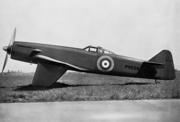
The Martin-Baker MB2 eight-gun fighter with its final tail configuration.

The MB2 started as a private venture around 1935 and closely followed Air Ministry Specification F.5/34 issued in 1934 for an eight-gun, 275 mph fighter aircraft. The MB2 was to be an easily produced and low cost fighter. Construction on the MB2 began in March 1936 and utilized the same steel tube construction techniques employed on the MB1. The wings and forward fuselage were covered by duralumin, and the rear fuselage and control surfaces were fabric covered. For simplicity and lightness, the MB2 had fixed undercarriage housed in streamlined fairings; the left fairing also incorporated an engine oil cooler. A pneumatic crash pylon would extend above the canopy to protect the pilot in the event of a nose-over during takeoff or landing.

Martin-Baker MB2 pylon

The MB2 with the crash pylon extended above the cockpit canopy. Note that the canopy provided a 360 degree view.

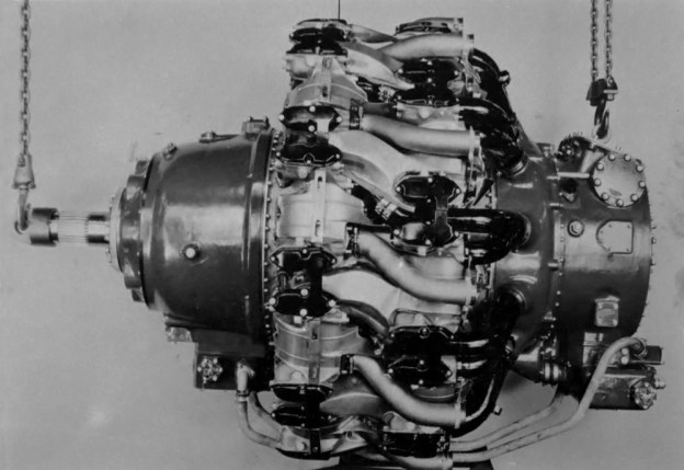
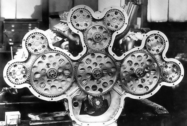
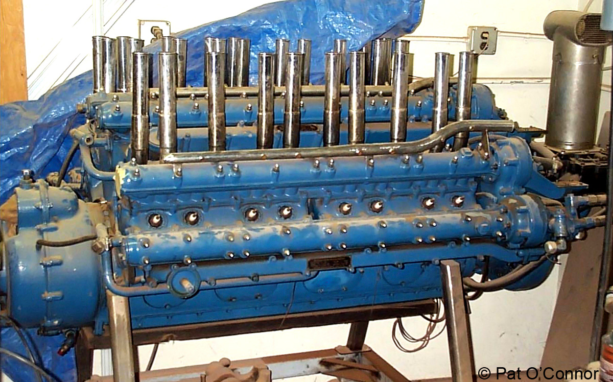
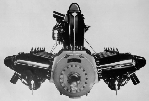
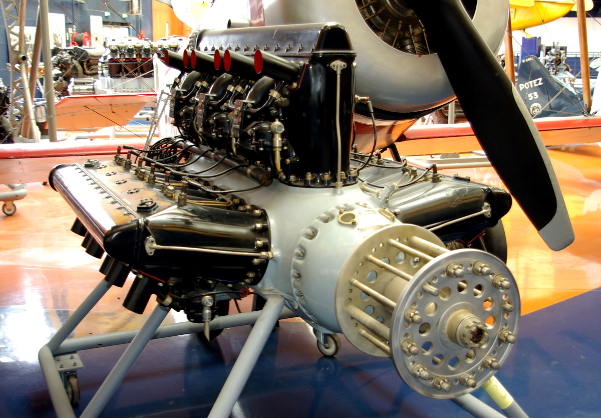
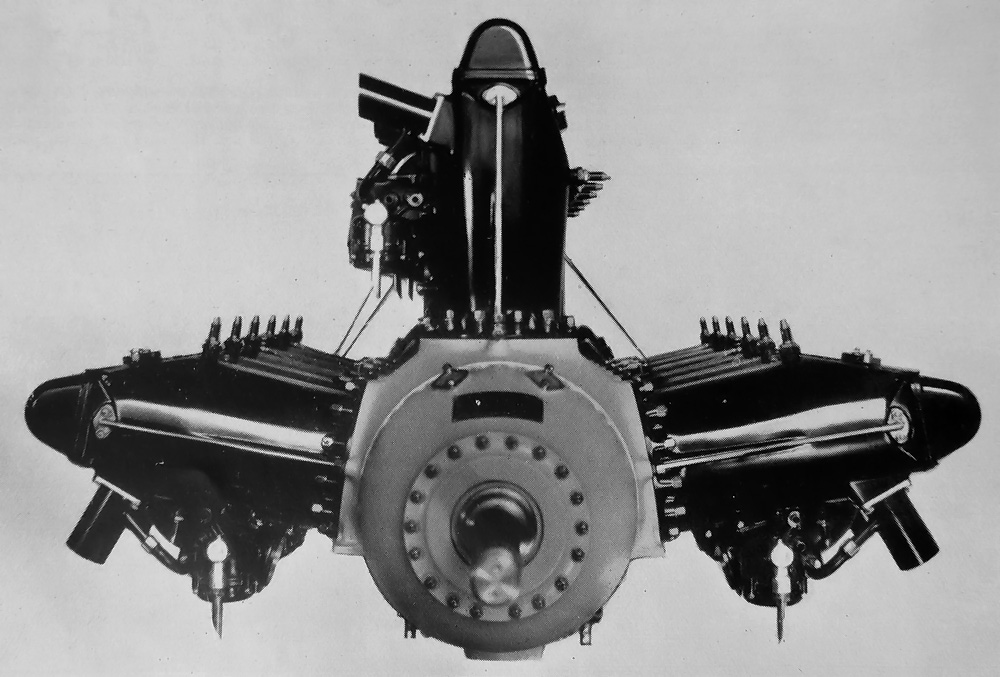
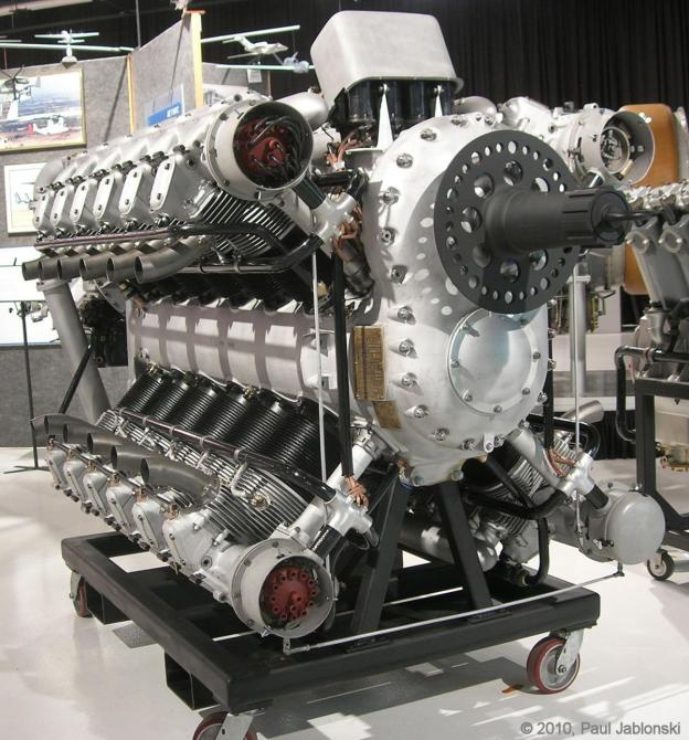
From the start, Martin had wanted a Rolls-Royce Merlin engine for the MB2, but none were available to the Martin-Baker Company. Napier was willing to loan Martin-Baker a Dagger IIIM engine, and the MB2 was designed around that engine. The Napier Dagger was an air-cooled, 24-cylinder, vertical H engine. With a 3.8125 in (96.8 mm) bore and a 3.75 in (95.25 mm) stroke, the Dagger displaced 1,027 cu in (16.8 L). The moderately supercharged Dagger IIIM produced around 805 hp (600 kW) at 4,000 rpm for takeoff and drove a 10.5 ft (3.2 m), fixed-pitch, two-blade, wooden propeller.

Martin-Baker MB2 marked as M-B-1

An early photo of the Martin-Baker MB2 when marked as M-B-1, with Capt. Baker at the controls. Note the exhaust manifold and how it differs from the other images.

The MB2 was designed with ease of maintenance in mind. All major components were easily accessible. The Dagger engine could be changed out faster than any other engine on any fighter then in service. Two men could remove the MB2’s armament, eight Browning .303 (7.7 mm) machine guns, in under five minutes (compared to 60 minutes for the Hurricane and 70 minutes for the Spitfire). Two men could reload the MB2, 300 rounds per gun, in 15 minutes (compared to 16 minutes for the Hurricane and 60 minutes for the Spitfire). The wings just outside of the gear could be removed in minutes to allow the aircraft to be easily transported or stored. The MB2 had a span of 34 ft (10.4 m), a length of 34 ft 9 in (10.6 m), and weighed 5,537 lb (2,512 kg). At 9,250 ft (2,820 m), the aircraft had a top speed of 305 mph (491 km/h), although some sources say 320 mph (515 km/h). The MB2’s ceiling was 29,000 ft (8,840 m).

Baker made the first flight in the MB2 on 3 August 1938. As first flown, the MB2 did not have any vertical tail. It was thought that the large main gear fairings and flat-sided fuselage would provide directional stability. The rear of the MB2’s fuselage tapered back to a vertical wedge that incorporated the aircraft’s rudder. Directional stability proved insufficient, and a small vertical tail stub was provided above the horizontal stabilizer. A conventional tail was later added to the MB2 after flight trials at Martlesham Heath in late 1938 indicated further improvement in directional stability were needed.

Martin-Baker MB2 with short tail

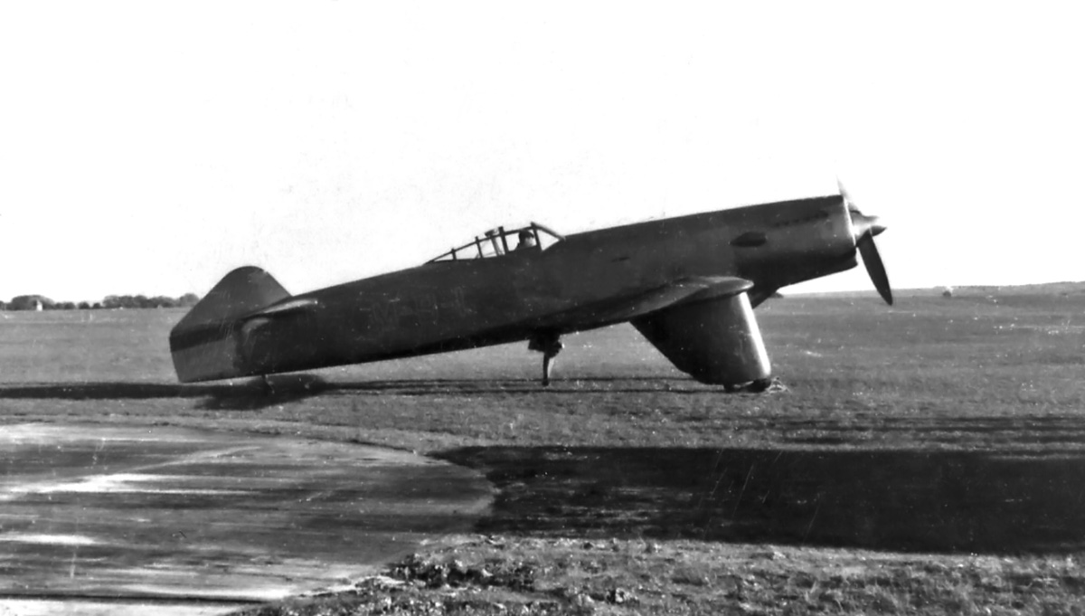
The MB2 with the revised small stub tail to provided better directional control over the original design having no tail. However, this tail configuration was still insufficient.

Early on, the MB2 carried “M-B-1” on the side of its fuselage for reasons that have not been made clear. While at Martlesham Heath, the MB2 was loved by ground crews for its ease of maintenance and serviceability. However, pilots found it lacking directional control, with insufficient rudder authority and heavy aileron control. Because of the control difficulties, it would not have made a good gun platform.

After the tail was modified to address the directional instability, the aircraft was re-evaluated at Martlesham Heath in late 1939. The new rudder was found to be satisfactory and effective, but the other flight controls still needed improvement. Designs were also made to fit the MB2 with fully retractable gear and change out the machine guns for cannons. But these changes were not pursued.

Martin-Baker MB2 flight

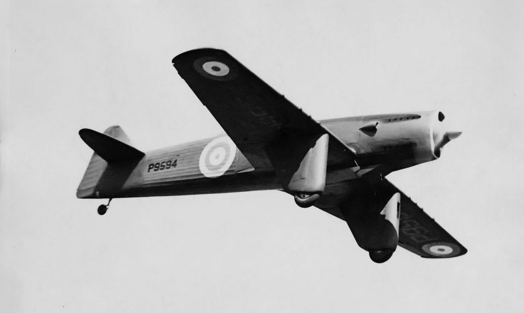
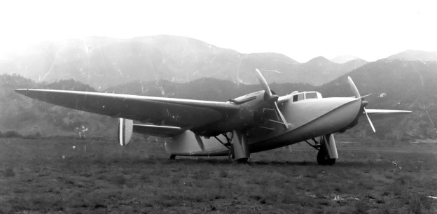
The Martin-Baker MB2 in flight with the final tail configuration. Note the opening for the oil cooler on the left main gear fairing and the exhaust ports on the cowling.

The Air Ministry purchased the MB2 in July 1939, but it was clear that there would be no further modifications or any chance of a production contract. While the MB2’s shortcomings could have been addressed, it would not have changed the fact that the aircraft was developed for a fighter specification over five years old. However, Martin-Baker was tasked to take what they had learned from the MB2 and develop a new Napier Sabre-powered fighter, which would become the MB3. The sole MB2 was scrapped in 1944. Designed and built by a small company with fewer than 40 employees, the MB2 exemplified simple and inexpensive construction techniques employed on an aircraft that was designed for ease of serviceability and whose performance could match fighter aircraft then in service.

Martin-Baker MB2

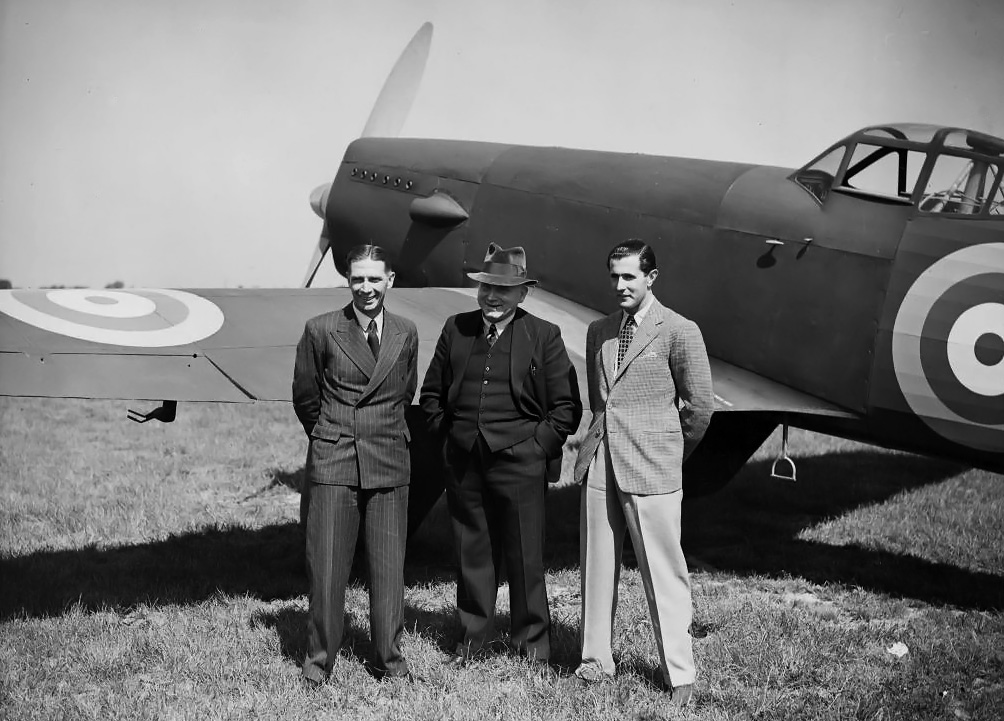
From left to right, Captain Valentine Baker, James Martin, and Francis Francis, who provided funding for the Martin-Baker Aircraft Company, stand next to the MB2.

Sources:
– “Martin-Baker Fighters,” by Bill Gunston, Wings of Fame Volume 9 (1997)
The British Fighter Since 1912 by Francis K. Mason (1992)
Interceptor Fighters for the Royal Air Force by Michael J.F. Bowyer (1984)
British Piston Aero-Engines and Their Aircraft by Alec Lumsden (1994/2003)
http://www.martin-baker.com/about/mb1-mb5

Hispano-Suiza 18Sbr

Hispano-Suiza 18R and 18Sb Aircraft Engines

By William Pearce

In the spring of 1928, after not participating in the Schneider Trophy contest for several years, the French Ministère de l’Air* (Air Ministry) set its sights on the competition for 1929. Aircraft for the race were ordered from Bernard and Nieuport-Delage. To be competitive, a new engine of around 1,200 hp was needed. The Ministère de l’Air put out orders for such an engine to Gnome-Rhône, Hispano-Suiza, and Lorraine. Only Hispano-Suiza was up to the challenge and responded with a new engine, known as the 18R.

Hispano-Suiza 18Sbr Musée de l'Air et de l'Espace

Hispano-Suiza 18Sbr W-18 engine on display in the Musée de l’Air et de l’Espace in Le Bourget, France. The 18Sb was essentially a detuned 18R. Note the carburetors on the sides of the cylinder banks and that each carburetor feeds two cylinders. (Duch.seb image via Wikimedia Commons)

The 18-cylinder, liquid-cooled Hispano-Suiza 18R had three very wide cylinder banks that formed a “W” (or broad-arrow) engine. The monobloc, six-cylinder banks were spaced at 80 degrees and derived directly from the Hispano-Suiza 12Nb V-12 engine of 750 hp (560 kW). The cylinders retained the 5.91 in (150 mm) bore and 6.69 in (170 mm) stroke of the 12Nb, but the compression ratio was increased from 6.2:1 to 10:1. The 18R’s total displacement was 3,300 cu in (54.1 L). The two valves per cylinder were actuated by a single overhead camshaft driven at the rear of the 18R. Each cylinder had two spark plugs positioned perpendicular to the cylinder but on opposite sides from one another. The spark plugs were fired by magnetos at the rear of the engine.

The engine’s connecting rods were of the master/articulated type, with the master rod for the vertical cylinder bank and articulated rods for the side cylinder banks. To keep the engine light, the crankcase and other components were made of Elektron, a magnesium alloy developed in Germany during World War I. The 18R was available with or without a Farmen (bevel planetary) propeller gear reduction, which weighed 132 lb (60 kg). The engine’s overall weight was 1,190 lb (540 kg) without gear reduction and 1,323 (600 kg) with gear reduction. The engine was 64.7 in (1.64 m) long without gear reduction and 78.5 in (1.99 m) long with gear reduction. The 18R had a width of 52.4 in (1.33 m) and a height of 46.1 in (1.17 m).

Hispano-Suiza 18Sbr

Front view of a Hispano-Suiza 18Sbr. The tube on the front of each cylinder bank supplied oil to the overhead camshaft.

The 18R had a planned output of 1,680 hp (1,253 kW) at 2,400 rpm. However, developmental issues delayed the engine, and neither it nor the aircraft it was to power were ready for the 1929 Schneider contest. The first 18R engine, a geared drive version, was delivered to Nieuport in October 1929, a month after the contest.

The Schneider contest racer from Nieuport-Delage was known as the NiD-450, and two were ordered. It was a low wing, wire-braced seaplane of conventional layout. When installed in the NiD-450, the 18R was limited to 1,200 hp (895 kW) at 2,000 rpm. For the NiD-450, the engine’s nine carburetors were placed between the cylinder banks. This limited the interference between the fairings for the side cylinder banks and the wing. Although the engine was installed and test-run in the NiD-450 in 1929, the aircraft did not undergo tests until February 1930. The first flight was made by Sadi Lecointe at the end of April. The NiD-450 was damaged in June when the engine cowling came free while in flight and struck the aircraft. Once repaired, the aircraft was damaged again in July when it crashed while taking off.

A further development of the NiD-450 built for possible use in the 1931 Schneider contest was the NiD-650. In fact, the second NiD-450 was finished as the first NiD-650, and the first NiD-450 was rebuilt and modified, becoming the second NiD-650. Still powered by the Hispano-Suiza 18R, the first NiD-650 was delivered on 11 February 1931. Lecointe made the first flight on 12 March, but the aircraft’s handling was not good. Modifications and test flights continued, but the aircraft crashed on 22 July. The pilot, Ferdinand Lesne, was not harmed. The second NiD-650 was flown on 31 August by Lecointe. The aircraft performance was less than what was needed for the Schneider contest, and there was not enough time for any improvement.

Nieuport-Delage NiD-650

Both Nieuport-Delage NiD-450s became NiD-650s, an example of which is seen here. Note how the side cylinder bank was housed in its own fairing, completely separate of the low-mounted wing. For the NiD-450/650, all nine of the 18R’s carburetors were installed between the cylinder banks.

The Schneider contest racer from Bernard was known as the HV120. Two were built, and the HV120 had a layout similar to the NiD-450. The HV120 used a direct drive 18R engine and was ready for tests in early 1930, long after the 1929 contest. For the HV120, the carburetors for the engine’s lower cylinder banks were placed under the banks. This allowed the side cylinder banks to be faired into the wings. Antoine Paillard undertook the aircraft’s testing and made the first flight on 25 March 1930. The highest recorded speed for the HV120 was 317 mph (510 km/h), far below the competition. Modifications were made for the HV120’s possible use in the 1931 contest, but by this time, the aircraft was mainly used for flight training while newer racers were prepared. Unfortunately, the first HV120 was destroyed when it crashed on 30 August 1931, killing its pilot, Georges Bougault, who was the leader of the French Schneider team. The second HV120 was ready for flight, but little effort was made to prepare it for the Schneider contest.

The Hispano-Suiza 18R had absolutely no success with the Schneider Trophy contest. The engine was delayed, but there were many issues with the racing aircraft as well. In an attempt to recoup its loss and make something out of the 18R, Hispano-Suiza detuned the engine for commercial use. Known as the 18Sb, the engine had its compression returned to 6.2, was limited to 2,000 rpm, and had an aluminum crankcase. With the changes, the engine had a respectable max output of 1,125 hp (840 kW) and a normal output of 1,000 hp (745 kW). With gear reduction the engine was known as the 18Sbr and weighed 1,300 lb (590 kg). Without rear reduction the engine was known as the 18Sb and weighed 1,138 lb (516 kg). Other dimensions were the same as the 18R, except the 18Sb’s height was slightly reduced to 45.3 in (1.15 m).

Bernard HV140

Bernard HV140 had the side banks of the Hispano-Suiza 18R faired into the wings. It is because of this that the carburetors for the lower cylinder banks were mounted under the banks.

Although many projects were proposed to use the 18Sb, few were actually built. One aircraft that probably should have remained a project was the Ford 14-AT (some say 14-A), the last of the Ford trimotors. Developed in relative secrecy, the blunt nosed Ford 14-A was an all metal monoplane built in 1932 by the Stout Metal Airplane Division of the Ford Motor Company. The aircraft had a wingspan of 110 ft (33.5 m), length of 80 ft (24.4 m), and was built to carry 40 passengers. Two 715 hp (533 kW) Hispano-Suiza 12Nc V-12 engines were buried in the wings, and a single 18Sbr W-18 was mounted on a pylon atop the aircraft.

The 14-AT tried numerous times to take flight, none of which brought success. Originally designed for Pratt & Whitney air-cooled radial engines (Henry Ford made the engine change), the heavy 14-AT would not leave the ground and was damaged in an attempt to pry it free from earth. Reportedly, Edsel Ford ordered the 14-AT quietly scrapped in 1933, without ever making a public appearance.

One Hispano-Suiza 18Sbr engine is preserved at the Musée de l’Air et de l’Espace (Air & Space Museum) in Le Bourget, France.

Ford 14-AT

The very large and unsuccessful Ford 14-AT. Note the four-blade propellers on the wings and the three-blade propeller for the high-mounted 18Sbr.

*Technically, France’s 1929 Schneider efforts were started by the Ministère de la Marine (Ministry of the Navy). The Ministère de l’Air was not established until October 1928 and subsequently took over the Schneider efforts and other aviation projects.

Sources:
Schneider Trophy Seaplanes and Flying Boats by Ralph Pegram (2012)
Hispano Suiza in Aeronautics by Manuel Lage (2004)
Aerosphere 1939 by Glenn Angle (1940)
Jane’s All the World’s Aircraft 1931 – 1933 by C.G. Grey
Beyond the Model T: The Other Ventures of Henry Ford by Ford Bryan (1997)

Piaggio P.23M front

Piaggio P.23M Transport Prototype

By William Pearce

The Piaggio P.23M was a prototype commercial transport aircraft intended for northern transatlantic flights. If flight testing was successful, the possibility existed to develop the unique aircraft for regular passenger service. Designed in 1934 by Giovanni Pegna, the P.23M was partly inspired by the Piaggio P.16 bomber prototype (also designed by Pegna). Two examples of the P.23M were ordered on 31 May 1934 and given the serial numbers MM 263 and MM 264.

Piaggio P.23M front

The elegant Piaggio P.23M transport prototype.Note the intakes above and below the spinner for funneling cooling air into the radiators for the tandem engines .

The P.23M was a four-engine, all-metal aircraft with twin tail fins and rudders. The underside of the aerodynamically clean fuselage had a keel, much like a flying boat, and was watertight. While the aircraft could not operate from the water, the keel fuselage design was incorporated to facilitate emergency water landings. This feature was reflected in the P.23M’s name, the “M” representing Marino (Marine) .

The P.23M’s wing was a semi-cantilever, inverted-gull design (similar to the P.16’s) and was supported by three struts on each side. Each wing carried a long nacelle that housed two Isotta-Fraschini Asso XI R engines mounted in tandem. The foreword engine drove a tractor propeller, and the rear engine drove a pusher propeller. Each nacelle also housed the radiators for the engine pair and the retractable main landing gear.

Piaggio P.23M side

The boat-like keel at the front of the P.23M’s fuselage can be seen fading toward the rear of the aircraft in this side view.

The Asso XI R engine was a 12-cylinder Vee with a 5.75 in (146 mm) bore and a 6.30 in (160 mm) stroke. Total displacement was 1,962 cu in (32.1 L), and the engine produced 900 hp (671 kW). The Piaggio P.23M had a wingspan of 88 ft 7 in (27.0 m) and was 54 ft 6 in (16.61 m) long. The aircraft’s empty weight was 16,290 lb (7,387 kg), and maximum weight was 40,651 lb (18,439 kg), resulting in an impressive useful load of 24,365 lb (11,052 kg). Calculated speeds were 249 mph (400 km/h) maximum and 186 mph (300 km/h) cruise. Cruising range was estimated at 3,167 miles (5,100 km). Climbing calculations indicated the P.23M could reach 13,125 ft (4,000 m) in 14 minutes.

The Piaggio P.23M first took to the air on 25 October 1935 at Villanova d’Albenga, Italy. Tragically, something during the flight went horribly wrong. The aircraft crashed, and both test pilots, Ciacci and Risso, were killed.

Piaggio P.23M rear

The P.23M’s inverted gull wing and twin tails can be seen in this rear view, along with the aerodynamically clean fuselage.

While the exact cause of the crash is not known, it could have had something to do with the aerodynamic effect of the tandem engines and propeller pulses on the twin tails. The design for the second P.23M (MM 264), which had not been built, was converted to a trimotor configuration and redesignated P.23T. As a further development of the P.23M, the Piaggio P.50 I heavy bomber retained the tandem engines in each nacelle, but the twin tails were replaced with a single tail. Subsequently, the P.50 II had a conventional layout for its four engines—each in a separate nacelle.

Ultimately, the P.23T trimotor transport proposal was abandoned, and an entirely new aircraft was designed and constructed as the P.23R. Despite the similar designation, the P.23R had nearly nothing in common with the P.23M. Neither the P.23 nor P.50 series of aircraft proved successful. However, they did provide much experience to facilitate development of the Piaggio P.108 heavy bomber of World War II.

Piaggio P.23M front 2

Another front view of the Piaggio P.23M. Note the right wing’s support struts and the missing cover on the left main gear.

Sources:
Italian Civil and Military Aircraft 1930-1945 by Jonathan W. Thompson (1963)
http://www.giemmesesto.org/Documentazione/Aerei/PIAGGIO_P-23.html
http://www.secretprojects.co.uk/forum/index.php?topic=15099.0
http://en.wikipedia.org/wiki/Piaggio_P.23

Allison X-4520 RRHTAB front

Allison X-4520 24-Cylinder Aircraft Engine

By William Pearce

When the United States entered World War I, the Allison Experimental Company (Allison), founded by James Allison, set out to construct equipment for the war effort. Previously, the company was known as the Allison Speedway Team Company, because James Allison was a co-founder of the Indianapolis Motor Speedway and was focused on automobile development. During the war, the Allison Experimental Company supplied some of the tooling for production of Liberty V-12 engines. Throughout and after the war, Allison was involved in designing and building various Liberty parts, including the epicyclic (planetary) gear reduction for the Liberty 12B (200 of which they constructed) and various other gear reduction units, gearboxes, and superchargers. Allison also developed and produced an inverted Liberty engine and air cooled cylinders for the Liberty. The Liberty was Allison’s first foray into aircraft propulsion; its next was the X-4520.

Allison X-4520 RRHTAB front

The restored Allison X-4520 24-cylinder, air-cooled engine carrying Allison serial number 1. Note the distributors on the front of each overhead camshaft.  (Paul Jablonski image via the Aircraft Engine Historical Society)

On 4 January 1921, the Allison Experimental Company changed its name to the Allison Engineering Company. By 1924, the Army Air Service (AAS) Power Plant Section at McCook Field, Ohio had designed a large 24-cylinder engine in an “X” layout. They asked Allison to refine their design and construct a prototype. The engine was given the AAS serial number 25-521 and also carried the Allison serial number 1.

The X-4520 had four banks of six air-cooled cylinders. The banks were arranged at 90 degree intervals around a common crankshaft housed in an aluminum, barrel-type crankcase. The cylinders had a 5.75 in (146 mm) bore, 7.25 in stroke (184 mm), and 4.9 to 1 compression ratio. Total displacement was 4,518 cu in (74 L). Each cylinder had two valves, and the exhaust valve was sodium cooled. The valves for each cylinder bank were actuated by a single overhead camshaft. At the front of each camshaft was a distributor that fired the two spark plugs per each cylinder for that bank. Each camshaft was driven by the crankshaft via a vertical shaft at the front of the engine.

Allison X-4520 AAS Early side sm

An early 1925 AAS drawing of the X-4520. The most notable differences between the drawing and the actual engine are that the drawing has the lower banks of cylinder staggered forward of the upper cylinders, and the intake manifolds exit the top and bottom of the rotary induction.

The flat top aluminum pistons had three rings above the piston pin and one ring below. Each of the six 3.5 in (89 mm) diameter crankpins was 4.3125 in (110 mm) long and accommodated two fork-and-blade connecting rods side-by-side. The top cylinder’s pistons were connected to the front fork-and-blade connecting rod. The bottom cylinders were staggered slightly to the rear, and their pistons were connected to the rear fork-and-blade connecting rod. The seven crankshaft main bearings were of the (Hoffman) roller type. Roller bearings were selected by the Power Plant Section because their reduced length allowed for a shorter, and therefore lighter, engine.

The engine had a 2 to 1 spur reduction gear and a rotary induction (fuel/air mixer or moderate supercharger) geared with a step-up ratio of 5 to 1. At 1,800 rpm engine speed, the propeller would turn 900 rpm and the supercharger 9,000 rpm. Two updraft carburetors fed the rotary induction at the rear of the engine. The air/fuel mixture was then distributed to each cylinder via manifolds that ran in the upper and lower Vees of the engine. The X-4520 was 108 in (2.74 m) long, 60 in (1.52 m) wide, 53 in (1.35 m) tall, and weighed around 2,800 lb (1,270 kg).

Allison X-4520 baffles

The Allison X-4520 with baffles surrounding sides of the engine to direct cooling air through the cylinder’s fins.

Allison completed the sole X-4520 engine in 1927, but no facilities existed that could handle the rated output of 1,200 hp (895 kW) at 1,800 rpm. At the time, it was one of the largest and most powerful aircraft engines ever built. It was not until 1931 that the engine was finally run by the Army Air Corps (AAC). While the engine produced 1,323 hp (987 kW) at 1,900 rpm, it also experienced cooling-issues, and a piston stuck in a cylinder during testing. By this time, the AAC had little interest in the engine, and the cause of the issues were never investigated.

The X-4520 was intended for a very large single-engine biplane bomber, most likely the Huff-Daland XHB-1. This aircraft had an 84 ft 7 in (25.8 m) span, was 59 ft 7 in (18.2 m) long, and was fitted with a 780 hp (582 kW) Packard 2A-2540 V-12 engine. By the time the X-4520 was tested, a design shift had occurred from the use of large single-engine aircraft to multi-engine aircraft. This left the X-4520 without an application, in addition to the technical issues experienced during testing.

Huff-Daland XHB-1

The huge Huff-Daland XHB-1 was originally to be powered by the X-4520. As events unfolded, the aircraft was powered by a Packard engine. The man standing under the nose of the aircraft gives a good indication of its immense size.

Even with the AAC’s lack of interest and the engine’s technical issues, the X-4520 was displayed at the Century of Progress Exposition in Chicago, Illinois in 1934. The engine was retained by the AAC and placed in storage at what would become Wright-Patterson Air Force Base in Dayton, Ohio. The X-4520 was disposed of as scrap around 1970 (apparently aviation history enthusiast Walter Spolata saved the engine). The X-4520 eventually found its way to the New England Air Museum in Windsor Locks, Connecticut, looking in rough shape after being in outside storage for a number of years. The engine was then acquired by the Rolls-Royce Heritage Trust Allison Branch in Indianapolis, Indiana; the trust restored the X-4520 and put it on display in 2010.

The restored Allison X-4520 on display at the Rolls-Royce Heritage Trust Allison Branch in Indianapolis, Indiana.

The Allison X-4520 on display at the Rolls-Royce Heritage Trust Allison Branch in Indianapolis, Indiana. Note the induction and how it differs from the 1925 drawing. (Paul Jablonski image via the Aircraft Engine Historical Society)

Sources:
Vee’s for Victory! The Story of the Allison V-1710 Aircraft Engine 1929-1948 by Daniel D. Whitney (1998)
Bearing Loads and Stress Analysis of the Model X-4520 Engine Rated 1200 B.H.P. at 1800 R.P.M. by Norman Tilley (1925)
The Allison Engine Catalog 1915-2007 by John M. Leonard (2008)
A Technical & Operational History of the Liberty Engine by Robert J. Neal (2009)
http://www.enginehistory.org/allison.shtml
http://www.nationalmuseum.af.mil/factsheets/factsheet.asp?id=2422

Bolkhovitinov S-2M-103 Sparka

By William Pearce

With the intention of creating a high speed light bomber, Viktor Bolkhovitinov designed what is commonly referred to as the Bolkhovitinov S or Sparka. During flight trials the Soviet Air Force (VVS) referred to the aircraft as S-2M-103, for skorostnoy (high speed) with two M-103 engines; however, a number of other designations have been applied over the years. The common “Sparka” designation means twin—because the aircraft had two engines mounted in tandem. Other designations are BBS-1 for blizhniy bombardirovshchik skorostnoy (short range bomber, high-speed), BB for blizhniy bombardovshchik (short range bomber), and LB-S for lyohkiy bombardirovshchik-sparka (light bomber-paired).

A good view of the twin engine Bolkhovitinov Sparka. Note the plexiglass glazing for the bombardier's downward view.

A good view of the twin-engine Bolkhovitinov Sparka. Note the plexiglass glazing for the bombardier’s downward view.

The Sparka was a low-wing aircraft of all-aluminum construction with stressed skin. The aircraft had a twin fin tail to increase the rear gunner’s field of fire. The undercarriage was fully retractable; the main gear retracted toward the rear, and the wheels rotated 90 degrees to lie flat within the wings. The pilot and navigator/bombardier/gunner sat in tandem under a long canopy. Between the pilot and second crew member was a small bomb bay for 882 lb (400 kg) of bombs. A plexiglass section on the bottom of the aircraft just aft of the bomb bay provided the bombardier a view of the ground. The aircraft was 43 ft 4 in (13.2 m) long and had a relatively short wingspan of 37 ft 4 in (11.38 m). The Sparka weighed 12,460 lb (5,652 kg).

The Sparka was powered by two Klimov M-103A engines positioned in tandem in the aircraft’s nose. This coupled engine package was designated M-103SP. Each engine drove half of the aircraft’s six-blade, coaxial contra-rotating propeller unit. This engine and propeller arrangement was similar to the FIAT AS.6 installed in the Italian MC.72 and the Hispano-Suiza 12Y installed in the French Arsenal VB 10. With this engine arrangement, the front engine drove the rear propeller, and the rear engine drove the front propeller via a drive shaft that ran through the Vee of the front engine.

Schematic of the paired Kimlov M-103 engines installed in the Bolkhovitinov Sparka with the rear engine's drive shaft through the Vee of the front engine.

Schematic of the paired Klimov M-103 engines installed in the Bolkhovitinov Sparka with the rear engine’s drive shaft passing through the Vee of the front engine.

The Klimov M-103 engine was derived from the M-100, which was a licensed copy of the Hispano-Suiza 12Ybrs. The M-103SP had a 5.83 in (148 mm) bore and a 6.69 in (170 mm) stroke. Total displacement was 2,142 cu in (35.09 L). The engine produced 960 hp (716 kW). A radiator was installed in a large duct just below the rear engine, and it cooled both of the Sparka’s engines.

Bolkhovitinov started design work on the Sparka in 1937, and prototype construction began in July 1938. The aircraft made its first flight in January 1940 (some say late 1939) with B. N. Kudrin at the controls. VVS testing took place from March through July 1940. The Sparka showed good speed, reaching 354 mph (570 km/h). However, the takeoff run was excessive, landing speeds were high, and visibility over the nose was impaired. In addition, some trouble was encountered with the rear engine’s propeller drive shaft breaking due to excessive vibrations. Even so, the aircraft received a positive assessment, noting that the installation of the tandem engines eliminated a considerable amount of drag over two separate nacelles.

Engine bay view of the two Kimlov M-103 engines.

Engine bay view of the two Klimov M-103 engines.

A new wing was designed with a NACA-230 airfoil section to improve takeoff and landing performance. The aircraft was tested with this new wing from September to December 1940, and it did improve the aircraft’s takeoff and landing characteristics.

The Sparka was reconfigured for a single 1,050 hp (783 kW) Klimov M-105P (some say 103P) engine, which was installed in the forward engine bay. The M-105P was a development of the M-103P and could be fitted with a cannon in the engine’s Vee to fire through the propeller hub. The M-105P retained the bore and stroke of the earlier M-103P (and M-103SP) engine. The aircraft was tested on skis in early 1942 but was underpowered with the single M-105P, attaining a top speed of only 249 mph (400 km/h).

In this side view, the glazing on the bottom of the Sparka can clearly be seen.

In this side view, the glazing on the bottom of the Sparka can clearly be seen.

Some say the single engine version was really a separate aircraft (known as S-1) that flew in January 1940 to test the airframe configuration. This seems unlikely because of the time frame involved. The twin-engine Sparka (S-2) would have been nearly complete by the time the single engine airframe test ship first took to the air, making major changes impossible and minor changes difficult. If the airframe test ship had issues, there would not have been enough time for any changes to be made before the official trials took place in March 1940. Not to mention that adding the power and weight of another engine would change the aircraft’s flight dynamics considerably.

Bolkhovitinov S skis

The single-engined Bolkhovitinov S on skis.

Regardless, development on the Sparka was abandoned in mid-1941, partially a result of the German invasion. However, further studies were made on the feasibility of the tandem engine arrangement powering a fighter, but these studies did not lead to the production of any aircraft. In addition, the factory where the Sparka was built was needed to produce the Petlyakov Pe-2 attack bomber.

Rear view of the Sparka showing the defensive machine gun installation.

Rear view of the Sparka showing the defensive machine gun installation.

Sources:
Soviet X-Planes by Gordon and Gunston (2000)
Soviet Air Power in World War 2 by Yefim Gordon (2008)
Soviet Combat Aircraft of the Second World War, Vol. 2 by Gordon and Khazanov (1999)
Aircraft of the Soviet Union by Bill Gunston (1983)
Russian Piston Aero Engines by Vladimir Kotelnikov (2005)
http://www.secretprojects.co.uk/forum/index.php/topic,4532.msg152239.html#msg152239
http://en.wikipedia.org/wiki/Bolkhovitinov_S

Beech XA-38 Grizzly air 2

Beech Aircraft Company XA-38 Grizzly

By William Pearce

In March 1942, the Beech Aircraft Company began design work on a two-seat heavy fighter to destroy enemy bombers. Since the Curtiss XP-71 had already been delegated this task, the Beech developed the design into an attack aircraft to replace the Douglas A-20 Havoc. Beech gave this aircraft the in-house designation Model 28 and submitted its proposal to the US Army Air Force on 23 September 1942. On 2 December 1942, the AAF ordered two prototypes and designated the aircraft XA-38; this was Beech’s first combat aircraft. Beech originally called the aircraft Destroyer, but the AAF changed the name to Grizzly. The XA-38 was similar in appearance to the Beech 18, but it was an all-new aircraft. The project was led by Bill Cassidy, and the aircraft was to be strong, maneuverable, and well-armed. Its mission was to destroy fortified gun emplacements, armored vehicles, tanks, submarines, and coastal surface vessels.

Beech XA-38 Grizzly air

The second Beech XA-38 Grizzly (serial no 43-11407), with all guns installed.

The XA-38 was a two-place, mid-wing aircraft with a slim fuselage and twin tails. The gunner sat in the rear of the fuselage and operated remote upper and lower turrets, each fitted with two Browning .50 cal guns. The ventral turret could be locked in the forward position and fired by the pilot in strafing attacks. In the nose of the aircraft were another two Browning .50 cal guns and a T15E1 (M10) 75 mm cannon. The nose swung open to service the guns and was even removable so that different armament could be used. The .50 cal guns each had 500 rounds, and the 75 mm cannon had 20 rounds. Each wing supported two hard points that could carry a combined total of 2,650 lb (1,200 kg) of ordinance or 600 gal (2,270 L) of fuel.

The T15E1 75 mm cannon had an 84 in (2.13 m) barrel that extended about 2 ft (.61 m) beyond the aircraft’s nose. The cannon was self-loading, 144 in (3.66 m) long, and originally weighed 1,800 lb (816 kg). However, through further development, the weight was reduced to 1,138 lb (516 kg). It fired a 26 in (.66 m) shell with a 15 lb (6.8 kg) projectile. The cannon consisted of a 75 mm gun (T9E2), 75 mm feed mechanism (T13), and the 75 mm gun mount (T15E1).

Beech XA-38 Grizzly above

Excellent view of the second XA-38, showing the slim fuselage. The aircraft was on a test flight over Kansas.

The Grizzly’s aluminum skin was entirely flush riveted, and the fully retractable gear, including tailwheel, was engineered for operations out of unimproved airstrips. The aircraft was powered by two Wright R-3350-43 engines producing 2,300 hp (1,715 kW) each. Each engine turned a 14.2 ft (4.32 m), three-blade Hamilton Standard propeller. The XA-38 could carry 640 gal (2,423 L) of fuel in its wings and an additional 185 gal (700 L) in the fuselage behind the pilot. The aircraft had a wingspan of 67.3 ft (20.5 m) and was 51.8 ft (15.8 m) long. It weighed 22,480 lb (10,197 kg) empty and had a maximum takeoff weight of 35,265 lb (15,995 kg). The XA-38’s climb rate was 2,170 fpm (661 m/m), and it had a service ceiling of 27,800 ft (8,475 m). Maximum speed at 3,100 ft (945 m) was 376 mph (605 km/h), and cruise speed at 16,000 ft (4,877 m) was 344 mph (554 km/h). The 45-degree flaps allowed the aircraft to land at 97 mph and operate out of a 2,500 ft (762 m) runway.

Beech XA-38 Grizzly air 2

Both XA-38 aircraft in flight. The dummy turrets can be see on the first XA-38 to fly (furthest from camera).

The aircraft program was met with long delays due to the unavailability of the R-3350 engines, remote turrets, and the 75 mm cannon. The Boeing B-29 had engine priority; the Douglas A-26 had the turrets; and the cannon was still being developed. The first XA-38 (serial no 43-14406) took to the air on 7 May 1944 with Vern Carstens at the controls. The turrets were still not available, so dummy turrets were substituted. In July 1944, the aircraft was flown to Tulsa, Oklahoma, where the 75 mm cannon was fitted and ground fired. Later in July, the Grizzly fired the cannon in-flight over Great Bend, Kansas.

Flight tests continued and minor issues were worked out. The aircraft performed very well, and during one early, low-level test flight, the XA-38 was able to pull away from the P-51B chase plane. Capt. Jack Williams evaluated the aircraft for the AAF and made 38 flights in the XA-38 between 13-24 October 1944. The aircraft was reported to be very maneuverable for an aircraft of its size and easy to fly through most aerobatic maneuvers. The aircraft was transferred to Dayton, Ohio for further evaluation on 7 July 1945. At some point, at least a mockup of the upper turret was added to the aircraft.

Beech XA-38 Grizzly 06

What must be a late image of the first Beech XA-38 Grizzly (serial no 43-14406) with what appears to be a mockup of the upper turret installed.

The second aircraft (serial no 43-11407) took to the air on 22 September 1945; Carstens was again at the controls. This aircraft had the correct turrets installed, and all weapons were operational. After initial flight tests, the XA-38 was transferred to Eglin Field, Florida for armament trials. Here, it amassed an additional 38 hours of flight tests, but there was little interest since the war was over.

The Grizzly’s main problem was that its engines were needed elsewhere. B-29 production left no spare R-3350s available for any type of A-38 production until mid-1945. By that time, the war was winding down, and there was no foreseeable need for the A-38. One of the XA-38s reportedly went to Davis-Monthan AFB, Arizona, but its ultimate fate is not recorded. The other aircraft was believed to be scrapped. The only remnant of the XA-38 Grizzly is the T15E1 cannon on display at the United States Air Force Armament Museum in Eglin AFB, Florida.

The T15E1 (M10) 75 mm cannon from the XA-38 as displayed in the United States Air Force Armament Museum. (Tom Fey image)

The T15E1 (M10) 75 mm cannon from the XA-38 as displayed in the United States Air Force Armament Museum. (Tom Fey image)

Sources:
Beech Aircraft and their Predecessors by A.J. Pelleteir (1995)
U.S. Experimental & Prototype Aircraft Projects by Bill Noton (2008)
American Attack Aircraft Since 1926 by E.R. Johnson (2008)
U.S. Aerial Armament in World War II, Vol. 1 by William Wolf (2009)
American Combat Planes of the 20th Century by Ray Wagner (2004)
– 75MM Cannon M10 display in the United States Air Force Armament Museum in Eglin AFB, Florida

Clerget 16 H Diesel Aircraft Engine

By William Pearce

In 1936, the French Air Ministry issued a specification for a flying boat able to carrying at least 40 passengers and 1,100 lb (500 kg) of cargo 3,725 miles (6,000 km) against a 37 mph (60 km/h) headwind. This large passenger aircraft was to be used on transatlantic service for both the northern and southern routes. In 1938, three projects were selected for prototype construction: the Potez-CAMS 161, the Lioré et Olivier H-49 (which became the SNCASE SE.200), and the Latécoère 631.

Clerget 16 H front

The 2,000 hp Clerget 16 H with four Rateau turbosuperchargers atop the engine. In between the cylinder banks is the camshaft housing.

The new transatlantic airliner would be a large aircraft, necessitating powerful engines. Pierre Clerget felt an entirely new engine was needed to power this aircraft. Clerget, an aircraft engine pioneer who had already designed and built a few diesel aircraft engines in his long career, decided to capitalize on the inherent safety and efficiency of a diesel engine. Diesel fuel offered an increase in fuel efficiency and was far less prone to accidental ignition, eliminating much of the fire risk common in early aviation.

Clerget spent much of 1937 designing the engine, and what emerged was a powerful V-16 diesel engine known as the Clerget 16 H. Because of its 16 H designation, the engine is often assumed to be of an H configuration. However, the “H” most likely represented “Huile,” a French word for oil, as diesel fuel is a type of fuel oil. The four-stroke 16 H engine was first displayed at the Paris Salon de l’Aviation (Air Show) in late 1938. The 16 H had a bore of 7.09 in (180 mm) and stroke of 7.87 in (200 mm). The engine’s total displacement was 4,969 cu in (81.43 L). The 16 cylinders were arranged at a 45 degree angle in two banks of eight cylinders. The compression ratio was 14 to 1. The direct drive engine had individual aluminum cylinders with a steel barrel for the aluminum piston. The exposed four valves per cylinder were actuated by roller rocker arms and short pushrods from the camshaft, that was situated in the Vee of the engine. The camshaft was driven from the crankshaft via a vertical drive shaft at the rear of the engine.

Clerget 16 H rear

The diesel Clerget 16 H showing the fuel injection pumps along the side of the engine and various accessories at the rear of the engine.

Fuel injection for each cylinder was provided by two Clerget injection pumps and two Clerget hydraulically-operated injectors. Groups of four pump units (to supply two cylinders) were arranged on the outside of the engine, with a total of four such groups on each side. The pumps along each side of the engine were driven by a camshaft running at half-engine speed. One complete set of pumps could be shut off for operating the engine at low speeds. Fuel was injected into the cylinder at a maximum of 8,500 psi (586 bar).

The 16 H used a two-piece aluminum crankcase. The single-piece crankshaft had eight throws and was supported by nine main bearings. Connecting rods were of the master and articulated rod type. Pressure lubrication was provided by a dry-sump system, and each bank of cylinders had its own water-cooling circulation system. Starting was achieved by an air-starter unit attached to the rear of the engine. The engine was 31.5 in (.8 m) wide, 49.2 in (1.25 m) tall, and 112.6 in (2.86 M) long. The 16 H weighed 3,750 lb (1,700 kg).

Four Rateau turbosuperchargers sat atop the Clerget 16 H engine. Each turbocharger served four cylinders (two on each side of the engine). The turbine spun by exhaust gases from the cylinders was at the top of the turbocharger, and the compressor that supplied air to the cylinders was at the bottom of the turbocharger. The turbochargers allowed the 16 H engine to maintain power up to 16,400 ft (5,000 m).

Clerget 16 H side

An early image of the Clerget 16 H without turbochargers.

First run on 17 May 1939, the 16 H could produce 1,500 hp (1,119 kW) without the turbochargers. With the turbochargers, the engine produced 2,000 hp (1,491 kW) at 2,200 rpm for takeoff and 1,600 hp (1,193 kW) at 1,800 rpm for continuous cruise. At cruise power, fuel consumption was 0.375 lb/hp/hr (228 g/kW/hr), and oil consumption was 0.020 lb/hp/hr (12 g/kW/hr).

With the German invasion of France on 10 May 1940, engine development and the transatlantic passenger seaplane were put on hold. The sole Clerget 16 H engine was destroyed during a bombing raid on Paris in 1940. There were some rumors that the engine was moved to Germany before the bombing, but nothing ever came of this. In October 1940, there was interest in building another 16 H, but no further development was undertaken. Pierre Clerget continued to work on other aircraft engine designs but was found dead in the Canal du Midi in Moissac, France on 22 June 1943—a sad end for a remarkable man. The cause of his death has never been explained.

The Germans restarted the transatlantic passenger seaplane program in March 1941, and an example of each prototype had been completed and flown by the end of 1942. These aircraft were subsequently destroyed in Allied bombing raids. After World War II, ten examples of the Latécoère 631 were built, each powered by six 1,600 hp (1,193 kW) Wright R-2600 engines. The aircraft entered service in 1947 but would not last long. After four of the Latécoère 631s had crashed in separate incidents, the remaining aircraft were banned from flying in 1955.

Latecoere 631 Lionel de Marmier

The inspiration for the Clerget 16 H: the transatlantic flying boat airliner. This Latécoère 631, named Lionel de Marmier after the French ace who served in WWI and WWII, disappeared over the South Atlantic with all 52 on board on 1 August 1948.

Sources:
Diesel Aviation Engines by Paul H. Wilkinson (1942)
Aircraft Engines of the World 1941 by Paul H. Wilkinson (1941)
Pierre Clerget: Un motoriste de génie by Gérard Hartmann (2004)
Flying Boats & Seaplanes by Stephane Nicolaou (1998)

Duesenberg 12-Cylinder Marine Engine and the Disturber IV

By William Pearce

In 1910, the relatively unknown Fred and Augie Duesenberg began designing what would become their walking beam engine. This style of engine had a unique valve arrangement in which horizontal valves, perpendicular to the cylinder axis, opened into a small space above the cylinders. The valves were actuated by very long and large rocker arms, referred to as “walking beams.” By 1913, Duesenberg engines had attracted some attention and were noticed by Commodore James A. Pugh.

Duesenberg Inline-12 Marine engine

The Duesenberg straight-12 marine engine of over 750 hp. Large aluminum covers protected the walking beam rockers of each cylinder pair.

Pugh was interested in building a boat to win the Harmsworth Trophy (British International Trophy for Motorboats) in 1914 and bring the trophy back to the United States. The Harmsworth Trophy was held each year by the country that won it the previous year. The British had won the trophy in 1913 (and 1912), and the 1914 race was to be held on Osborne Bay, England. Pugh was building a 40-foot (12.2 m) hydroplane named Disturber IV and needed powerful engines to ensure victory. Pugh brought the Duesenbergs into the project, and the Duesenbergs began designing a truly unique engine to power Pugh’s new boat.

Duesenberg Straight-12 aluminum crankcase

The one-piece aluminum crankcase for the Duesenberg straight-12 engine.

The Disturber IV was to be powered by two separate straight 12-cylinder engines. Each engine was over 10-feet (3 m) long and was comprised of six two-cylinder blocks mounted on a one-piece crankcase. Each two-cylinder block was water-cooled with the intake valves in the middle of the block and the exhaust vales on the outside. The intake and exhaust valves were operated by long walking beam rockers. A single updraft carburetor provided the fuel/air mixture to a split manifold that fed four cylinders. Each cylinder had two spark plugs. Lubrication was provided by a pressurized oil system, a now-universal concept that was just being introduced at the time. The single-piece crankshaft was supported by seven main bearings.

The use of aluminum was rare for the time, yet the Duesenbergs used it extensively in the engine’s design. The crankcase was one of the largest aluminum forgings made at the time and weighed 365 lb (166 kg) before the final machine work. Magnalite aluminum pistons were used, and the walking beam rocker arm covers were aluminum.

The inline 12-cylinder engine had a bore of 6.75 in (171 mm) and a stroke of 7.5 in (191 mm). Total displacement was 3,221 cu in (52.8 L). The engine developed 750 hp (559 kW) at 1,500 rpm and 800 hp (597 kW) at 1,600 rpm. While it is possible that more power could have been obtained at a higher rpm, the often quoted 900 hp (671 kW) seems a little optimistic. The engine weighed 2,700 lb (1,225 kg). With both engines installed in Disturber IV and running at full speed, total fuel burn was reported at 132 gallons (500 L) per hour.

These mighty 12-cylinder engines were built at the Duesenberg Motor Company factory in St. Paul, Minnesota. The engines were finished and installed in Disturber IV in mid-1914. The installation of the engines was mirrored so that the intake of the left engine was on the left side and the intake of the right engine was on the right side. This effectively allowed the engines to run in opposite directions. Thus, each engine’s single propeller rotated in opposite directions. The propellers were 24 in (610 mm) in diameter with a 40 in (1 m) pitch. Through a step-up gearbox with a ratio of 1.25 to 1, each propeller turned at 2,000 rpm while the engine speed was 1,600 rpm.

The Disturber IV being launched on he Chicago River 2 July 1914. (Image DN-0063061, Chicago Daily News negatives collection, Chicago History Museum)

The Disturber IV being launched on the Chicago River on 2 July 1914. (Image DN-0063061, Chicago Daily News negatives collection, Chicago History Museum)

On 2 July 1914, the Disturber IV was officially launched on the Chicago River. It underwent trials for a short time, achieving speeds in excess of 50 mph (80 km/h), before it was shipped to New York on 12 July 1914. In New York, it was loaded on the S.S Minnetonka and shipped to Cowes, England for the Harmsworth Trophy race to be held on 15-18 August 1914. Augie Duesenberg accompanied the boat to ensure the engines would be trouble free. While the Disturber IV was in transit, Archduke Franz Ferdinand of Austria was assassinated, World War I began, and the Harmsworth Trophy was cancelled. The Disturber IV arrived in England only to be immediately shipped back to the United States without ever touching the water.

It had been a rushed pace from the inception of the 12-cylinder engines to the voyage back to the United States. Now with spare time on his hands, Augie began to think of ways to improve the 12-cylinder engines. After arriving back in the United States, the engines were shipped back to the Duesenberg factory in St. Paul where they were disassembled and modified. The exact extent of the modifications are not known, but it was during this rebuild that the large, water-jacketed exhaust manifold was replaced by individual, vertical exhaust stacks.

Disturber IV July 1914

Disturber IV in July 1914 with the large, water-jacketed exhaust manifold atop each engine and leading out the boat’s stern.

By October 1914, the 12-cylinder engines were back in Disturber IV, and the boat was turned loose on Lake Michigan. Pugh, accompanied by mechanics Charles Swanson and Henry Suttkas, won a special race off the coast of Chicago, Illinois on 20 October 1914. Two 14.83 mi (23.87 km) laps were run for a total distance of 29.66 mi (47.74 km). Disturber IV completed the first lap at a record speed of 56.6 mph (91.1 km/h). The second lap was completed at 47.0 mph (75.6 km/h), and the boat averaged 51.4 mph (82.7 km/h) over the total course. Disturber IV finished 17 minutes ahead of the second place boat.

Disturber IV Duesenberg

By October 1914, the Duesenberg engines in the Disturber IV had been modified with individual exhaust stacks. The pipes leading overboard were the cooling water outlet for each cylinder pair. Note the intake manifolds on the right engine.

In 1915, the American Speed Boat Championship was held over three days in early September on Lake Michigan. Each day a two lap race was made over a 15.25 mi (24.54 km) course for a total distance of 30.5 mi (49.09 km). The winner of the first day’s race would receive the Wrigley Trophy. During the first race, Disturber IV was in the lead after completing the first lap at 55.4 mph (89.2 km/h). The second lap was completed at 44.7 mph (71.9 km/h), and the boat averaged 49.5 mph (79.7 km/h) over the entire distance. Disturber IV won the Wrigley Trophy—and finished nearly 10 minutes ahead of the second place boat, Miss Detroit. During the second day’s race, Disturber IV turned the first lap at 55.3 mph (89.0 km/h) and the second at 55.2 mph (88.8 km/h), averaging 55.2 mph (88.8 km/h) over the 30.5 mi (49.09 km/h) total distance. Disturber IV was undefeated the third day and won the American Speed Boat National Championship.

A few days later on 12 September 1915, with the Duesenberg engines running at a smooth 1,600 rpm, Pugh and the Disturber IV became the first to break the mile-a-minute mark on water. Pugh made six timed speed runs on Lake Michigan near Chicago. His fastest run was 61.2 mph (98.5 km/h), but is often reported as 62 mph (99.8 km/h), and another run was at 60.4 mph (97.2 km/h). Disturber IV’s six run average was at 59.2 mph (95.3 km/h).

Disturber IV 1915 Race

Disturber IV in the 1915 American Speed Boat Championship on Lake Michigan. In the background are Peter Pan and Miss Detroit.

Late in 1915, Pugh put Disturber IV in storage and stated he would not race again until the next international meet. Pugh had built the Disturber IV solely to win the Harmsworth Trophy, and he found dominating other boats on Lake Michigan was not very fulfilling. With World War I raging, all international meets had been cancelled until the end of hostilities. What Pugh did not know was that the war would continue for another three years, and the next Harmsworth Trophy race would not be held until 1920. When peace did return, the world was a different place. The war had advanced engine technology, and the powerful Disturber IV was no longer on the cutting edge. The ultimate fate of the Disturber IV and its straight-12 Duesenberg engines is not known.

Disturber IV’s Duesenberg engines attracted so much interest that the Loew-Victor Company retained Fred Duesenberg as a designer. Fred went on to design six- and eight-cylinder engines based on the 12-cylinder engine’s design. In early 1917, Duesenberg Motor Company and the Loew-Victor Engine Company combined to form the Duesenberg Motors Corporation. Although it was not a direct path to the Duesenberg automobile, the engines for the Disturber IV helped open the door to the Duesenberg’s future endeavors.

Sources:
– “Walking Beam on Water” by Joseph Freeman, Automobile Quarterly, Vol. 30, No. 4 (1992)
– “A Large Aluminum Crank Case,” The Foundry, July 1914
– “Disturber Makes Record at Chicago” Power Boating, December 1914
– “Early Days of Aluminum Pistons” by Joseph Leopold, The Automobile, 7 October 1915
– “Chicago Races,” The Rudder, October 1915
– “Disturber IV Sets Mile-a-Minute Mark” by Jack Proctor, Sporting Life, 25 September 1915
Duesenberg Aircraft Engines: A Technical Description by William Pearce (2012)

Wright Aeronautical R-4090 Cyclone 22 Aircraft Engine

By William Pearce

In the early 1940s, Wright Aeronautical decided to utilize their 18-cylinder R-3350 engine as the basis for a new engine to compete with the Pratt & Whitney R-4360. The new engine developed by Wright was the R-4090 Cyclone 22 (Wright model no. 792C22AA). It used 22 R-3350 cylinders arranged in two rows of 11 cylinders. The R-4090 is one of only a few radial engines with 11 cylinders per row. It is also one of only three 22-cylinder aircraft engines ever built.

The 22-Cylinder Wright R-4090 engine. (Aircraft Engine Historical Society image)

The 22-Cylinder Wright R-4090 engine of 3,000 hp (2,237 kW). (Aircraft Engine Historical Society image)

The air-cooled Wright R-4090 had a 6.125 in (155.6 mm) bore and 6.3125 in (160.3 mm) stroke. Total displacement was 4,092 cu in (67.05 L) and the engine’s compression ratio was 6.85 to 1. The Cyclone 22 had a two-speed, single-stage supercharger and gave 3,000 hp (2,237 kW) at 2,800 rpm for takeoff. For continuous output, the engine produced 2,400 hp (1,790 kW) at 2,600 rpm. However, increased performance was expected with further engine development. The R-4090 had a diameter of 58 in (1.47 m), was 91 in long (2.31 m), and weighed 3,230 lb (1,465 kg).

The crankcase was a steel forging, following a construction practice pioneered by Wright and used on other Cyclone engines. The three-piece crankshaft was built up through the two one-piece master connecting rods. Ten articulating rods were attached to each master rod. Each cylinder was constructed in typical Wright fashion and had 3,900 sq in (2.52 sq m) of cooling fin area. Each cylinder’s hemispherical combustion chamber had two valves; the exhaust valve was sodium-cooled. It appears that the .333 to 1 propeller gear reduction was provided by Wright’s standard, multi-pinion planetary gear system. The supercharger and accessory drive section was very similar to that used on the R-3350 engine. However, the supercharger had a 14 in (356 mm) impeller and gear ratios of 5 to 1 and 7 to 1.

Front of view of the Cyclone 22 showing the 22 R-3350 cylinders tightly packed around the forged steel crankcase. (Aircraft Engine Historical Society image)

Front of view of the Cyclone 22 showing the 22 R-3350 cylinders tightly packed around the forged steel crankcase. (Aircraft Engine Historical Society image)

The R-4090 possessed similar power and weight characteristics to early Pratt & Whitney R-4360 engines. While developing the Cyclone 22, Wright was preoccupied with serious developmental issues of the very high priority R-3350 engine and ongoing development of the 42-cylinder R-2160 Tornado; not much time or manpower remained for the R-4090. As a result, only a few examples of the Cyclone 22 were built, and it is doubtful that the engine ever flew. Perhaps three R-4090 engines were completed: two XR-4090-1 engines with a single propeller shaft and one XR-4090-3 engine with a coaxial shaft for contra-rotating propellers. The XR-4090-3 weighed an additional 30 lb (13.6 kg) for a total of 3,260 lb (1,478 kg). In addition, the XR-4090-3 was to have a two-speed nose case to maximize propeller and engine speed efficiency for maximum power and cruise power. Ultimately, the R-4090 Cyclone 22 was abandoned so that more resources could be used for the R-3350 Cyclone 18.

Radial engines with 11-cylinder per row are very rare. With so many cylinders, the engine diameter becomes very large, and the valve train can be crowded and complex. In addition, difficulties can arise with so many power pulses on each crankpin.

The R-4090 was very close to the same power and weight as the Pratt & Whitney R-4360 at this stage of development.(Aircraft Engine Historical Society image)

The R-4090 was very close to the same power and weight as the Pratt & Whitney R-4360 at this stage of development. (Aircraft Engine Historical Society image)

During World War I, Clerget developed an 11-cylinder rotary engine of 200 hp (149 kW), designated the 11E. Another World War I-era 11-cylinder rotary of 200 hp (149 kW) was developed by Siemens-Halske and designated the Sh.III. The Sh.III was unusual in that its crankshaft rotated one direction within the engine while the crankcase, with propeller attached, rotated in the opposite direction. The result was 1,800 rpm of engine speed with only 900 rpm of propeller speed—an ideal speed in the days of fixed-pitch propellers and no gear reduction. Far removed from aviation, Nordberg Manufacturing Company made a successful 11-cylinder, two-stroke, diesel, stationary, radial engine of 1,655 hp (1,234 kW) at 400 rpm for industrial use.

Other examples of 22-cylinder, twin-row radial engines include the Mitsubishi A21 (Ha-50), with a displacement of 4,033 cu in (66.1 L) and an output of 2,600 hp (1,939 kW) and the Hitachi/Nakajima [Ha-51], with a displacement of 2,673 cu in (43.8 L) and an output of 2,450 hp (1,827 kW). Both of these engines were developed by the Japanese during World War II and, like the Wright R-4090, never entered production. Clerget also studied a 22-cylinder engine between the wars, but it never progressed beyond the design phase.

Rear view of the R-4090 showing the suppercharger and accessory section that appears to be the same as that found on the R-3350. (Aircraft Engine Historical Society image)

Rear view of the R-4090 showing the supercharger and accessory drive section which is very similar to that found on the R-3350. (Aircraft Engine Historical Society image)

Sources:
http://www.enginehistory.org/Piston/Wright/R-4090/Curtiss-WrightR-4090.shtml
Allied Aircraft Piston Engines of World War II by Graham White (1995)
R-4360: Pratt & Whitney’s Major Miracle by Graham White (2006)
http://www.ww2aircraft.net/forum/engines/11-22-cylinders-radials-33342.html
Model Designation of U.S.A.F. Aircraft Engines (1950)
The Wright Cyclones by Wright Aeronautical Corporation (1942)

Duesenberg W-24 Marine Engine

By William Pearce

Although his father was a co-founder of the Dodge Brothers Company, progenitor to today’s Dodge automobile company, Horace Elgin Dodge Jr. did not follow his father into the automobile business. But like his father, he was very interested in watercraft. In 1923, after his father had passed, he founded Dodge Boat Works in Detroit, Michigan. This venture was backed by a $2 million investment from his mother, Anna Thompson Dodge.

Side view of the J. Paul Miller-developed Duesenberg W-24 engine.

Side view of the J. Paul Miller-developed Duesenberg W-24 engine.

Dodge was very involved in boat racing, and he wanted to create a boat that would be unbeatable. In 1925, Dodge approached Duesenberg Brothers Racing to build an engine to propel him to victory in the Gold Cup race. An agreement was made, and a contact was signed on 27 January 1926—$32,500 for the construction of two complete engines with enough spare parts to build a third. The first engine was to be delivered on 15 June 1926, with the second following on 6 July 1926. Although Fred Duesenberg was involved with the engine project, it was most likely Augie Duesenberg who did the majority of the work.

The contracted engine was essentially three straight-eight engines on a common aluminum crankcase, creating a W-24. Why a “W” engine configuration was chosen is not known, but it does provide for a powerful engine in a fairly compact space. At this same time in history, the Napier Lion W-12 engine was powering record-setting air, land, and marine speed machines, and it is easy to see how the Lion could have served as inspiration.

Front view of the Duesenberg W-24 under construction.

View of the Duesenberg W-24 under construction.

The engine’s bore was 2.875 in (73 mm) and stroke was 4.0 in (102 mm), giving a total displacement of 623 cu in (10.2 L). The two side banks were angled 60 degrees from the center vertical bank. Each of the W-24’s engine banks was made up of two four-cylinder blocks with integral heads. The first four-cylinder blocks were supposedly made of cast iron, but later cylinder blocks were cast aluminum with steel cylinder liners. The engine’s single crankshaft was supported by five main bearings. The connecting rods were of the tubular type, with the master rod in the center bank and an articulated rod for each outer bank.

Four valves per cylinder operated in a pentroof combustion chamber. All together, the engine’s 96 valves took about a week of labor to adjust. The valves were actuated in each engine bank by dual overhead camshafts that extended the length of the engine. The camshafts were geared to the crankshaft via idler gears. Each block of four cylinders had five exhaust ports. The three middle exhaust ports each shared two exhaust valves. Exhaust from each bank was collect in a single water jacketed manifold. One spark plug was installed in each cylinder and fired by a camshaft-driven Delco distributor mounted at the rear of each cylinder bank.

The complex gear-drive arrangement for the camshafts at the rear of the 24-cylinder Duesenberg.

The complex gear-drive arrangement for the camshafts at the rear of the 24-cylinder Duesenberg. The pinion on the crankshaft had 17 teeth, the intermediate gears had 74 teeth, and the camshaft gears had 34 teeth. The center intermediate gear engaged an idler gear that had 45 teeth. The gearing drove the camshafts at half engine speed.

Initially, one updraft carburetor fed air to each of the six four-cylinder blocks. Poor fuel distribution resulted, and the engine never ran well. The updraft carburetors were replaced with downdraft carburetors, and the W-24’s running improved, but it was still not perfect. The six downdraft carburetors were replaced by 12 Zenith downdraft carburetors, improving performance yet again. Finally, 12 Holley downdraft carburetors replaced the Zeniths, and the engine began to run smoothly. Although running better than ever, the W-24 only produced a disappointing 475 hp (354 kW).

The first engine was delivered to Dodge in 1927. Earlier that year, J. Paul Miller began working at the Duesenberg factory and was involved with W-24 engine for many years. Some of Miller’s first changes were installing I-beam connecting rods in place of the tubular ones and replacing the Delco distributors with Bosch magnetos. From 1929 to 1935, Miller worked for Dodge and continued to develop the engine. Unfortunately for Dodge, the 24-cylinder engines brought nothing but frustration. As a result, he never paid Duesenberg the last $2,000 for the engines.

Rear of the 24-cylinder Duesenberg showing two two-barrel carburetors feeding the supercharger. Note the Bosch magnetos mounted driven by the camshafts.

Rear of the 24-cylinder Duesenberg showing two two-barrel carburetors feeding the supercharger. Note the camshaft-driven Bosch magnetos.

The 1931 Gold Cup race was held on Lake Montauk in New York, and the W-24 engine was installed in Dodge’s Miss Syndicate III boat. Miss Syndicate III failed to finish the first heat. In 1932, Miss Syndicate III had been renamed Delphine V. Dodge Sr. had named a yacht after his daughter, and Dodge Jr. continued the “Delphine tradition,” naming numerous boats after his sister. Again, the Gold Cup race was held on Lake Montauk in New York. During the first heat race, the W-24-powered Delphine V dropped out after three laps. Dodge entered five boats for the 1933 Gold Cup race held on the Detroit River. A 24-cylinder Duesenberg was installed in two of the entries: the new Delphine VIII and the new Delphine IX. That year, Delphine VIII failed to start, and Delphine IX did not finish a single heat. In 1934, in disgust, Dodge sold one (but probably both) W-24 engine to Herb Mendelson.

Before the sale, Dodge was inspired by the performance of the supercharged Packard engine in one of this other boats, Delphine IV. Since a rule change allowed superchargers to be used starting in 1935, Dodge had commissioned Miller to design a supercharger for the W-24. This unfinished project was sold to Mendelson, and Miller was retained by Mendelson to continue the work on the engine. It was Miller’s refinements of the supercharged engine that really brought the W-24 to life. The supercharger used an 8 in (203 mm) impeller and spun at 6.5 times crankshaft speed (32,500 rpm at 5,000 rpm engine speed), creating 15 psi (1.03 bar) of boost. Initially, two two-barrel carburetors were used on the supercharged engine, but these were replaced by a single four-barrel Stromberg carburetor. Along with new Miller-designed intake manifolds, the fuel distribution problems were finally solved. The exhaust manifolds were discarded and replaced by 30 vertical exhaust stacks extending into the air. With the changes, the engine weighed 1,400 lb (635 kg) and was referred to as the “Mendelson-Duesenberg W-24.” The engine began to run like a champion and now produced over 850 hp (634 kW) at 5,000 rpm. Reportedly, at full song the engine produced a sound like nothing else on earth.

The W-24 being installed in in the Arena-designed Notre Dame by Gene Arena, Walter Schmid, and Bert MacKenzie.

The W-24 being installed in in the Arena-designed Notre Dame by Gene Arena, Walter Schmid, and Bert MacKenzie.

Mendelson installed the W-24 into his boat, the Clell Perry-designed rear-engined Notre Dame (the first). Its first competition was the 1935 President’s Cup race on the Potomac River. Perry was the driver and won the race. In 1937, Perry was again at the controls when the W-24-powered Notre Dame won the Gold Cup race, held on the Detroit River, averaging 63.68 mph (102.48 km/h) over the 90 mile (145 km) course.

While making a high speed run on the Detroit River in preparation for the 1938 Gold Cup race, Perry was injured when the new Notre Dame (the second) boat went out of control and flipped over. (This accident possibly destroyed one of the W-24 engines.) The new Notre Dame was repaired, and Dan Arena took over the driving duties. He finished second in the President’s Cup race but did not like the boat’s stability. Mendelson asked Arena what he thought was needed to cure the stability issues, and Arena said, “Build another boat.” Mendelson agreed, and Arena designed a new 22 ft (6.7 m) boat, again named Notre Dame (the third), with the W-24 engine placed in front of the driver.

Dan Arena (standing) preparing to run the W-24-powered Notre Dame with his brother Gene as the riding mechanic, as Bert MacKenzie makes final preparations.

Dan Arena (standing) preparing to run the W-24-powered Notre Dame with his brother Gene as the riding mechanic, as Bert MacKenzie makes final preparations.

After a bit of a rough start, Arena won the 1939 and 1940 President’s Cup races in the new Notre Dame. In 1940 on the Detroit River, the W-24 powered the Notre Dame to a new class speed record of 100.987 mph (162.523 km/h). The boat was placed in storage during World War II but was taken out in 1947 and won the Silver Cup race on the Detroit River and finished second in the President’s Cup race. By this time, competitors were installing WWII surplus Allison engines in their boats, and the Duesenberg W-24 could no longer compete. The engine was removed and placed in storage.

At least one Duesenberg W-24 engine survives along with many spare parts. As of 2013, the engine is owned by Gerard Raney and has been rebuilt for installation in a Notre Dame (the third) replica that is under construction. In the mid-1990s, Miller and Arena were both involved in the project, which is based out of the San Francisco Bay Area. Undoubtedly, the engine and boat combination will be quite a sight when the project is finished.

Duesenberg W-24 1996 copy

The surviving Duesenberg W-24 engine owned by Gerard Raney as seen in 1996. Note that each cylinder bank is made up of two four-cylinder blocks; the gap between the blocks is visible on the bank nearest the camera. The camshaft housings extend the length of the engine. (Pat O’Connor image)

Sources:
– “The Duesenberg W-24” by Dean Batchelor, Road & Track, August 1992
– “That Kid From Oakland” by Frank Gudaitis, Nautical Quarterly, No. 40, Winter 1987
– “They Always Called Him Augie” by George Moore, Automobile Quarterly, Vol. 30, No. 4 (1992)
The Classic Twin-Cam Engine by Griffith Borgeson (1979/2002)
Classic American Runabouts: Wood Boats, 1915-1965 by Ballantyne and Duncan (2005)
http://www.vintagehydroplanes.com/apba_history/notebook/1996_08.html
The Dan Arena Story by Fred Farley – ABRA Unlimited Historian
The Notre Dame Story by Fred Farley – ABRA Unlimited Historian
1933 – The Year of the Dodge Navy by Fred Farley – ABRA Unlimited Historian
http://www.findagrave.com/cgi-bin/fg.cgi?page=sh&GRid=14820517