brayton-1876-inverted-walking-beam-engine

Brayton Ready Motor Hydrocarbon Engine

By William Pearce

With the proliferation of steam power in the late 1800s, many inventors looked to create a simpler and more efficient engine. Rather than having combustion occur outside the engine, as with a steam engine, designers sought to create an internal combustion engine, in which the piston was driven by the expansion of a volatile gas mixture after it was ignited. George Brayton of Boston, Massachusetts was one such inventor, and while his designs would forever influence the internal combustion engine, he never achieved the same level of recognition as many of his contemporaries.

brayton-1872-patent-ready-motor-engine

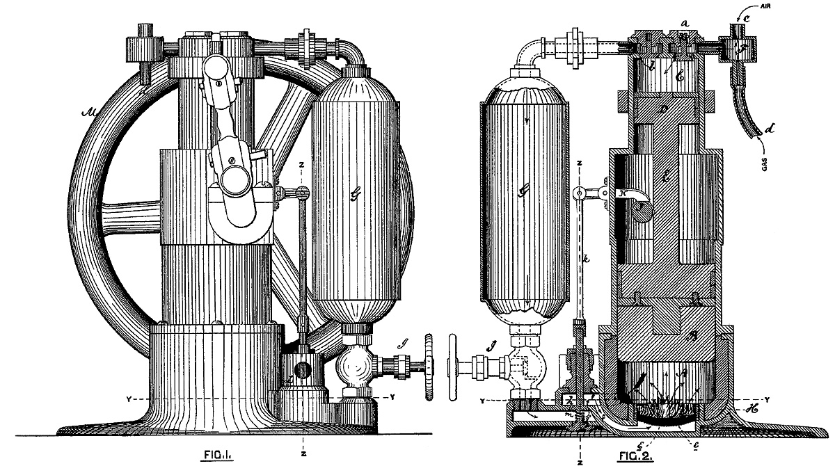
Patent drawings of George Brayton’s 1872 engine. Gas and air was drawn into cylinder C, compressed by piston D, and stored in reservoir G. The mixture was then released into cylinder A and ignited as it passed through wire gauze e. As the mixture combusted and expanded, it acted on piston B.

Brayton was an inventor, engineer, and machinist who had experience with steam engines. Some of his internal combustion engine experiments date back to the early 1850s, but he began serious development around 1870. In 1872, Brayton patented a new type of engine, the first in a series that became known as the Brayton Ready Motor. The name “Ready Motor” described the fact that the engine was immediately ready for operation, unlike a steam engine. The Brayton engine was also called a “Hydro-Carbon Engine.” The engine used fuel (hydrocarbons) mixed with air as the working fluid that directly acted on the piston, rather than the fuel heating some other working fluid, as with a steam engine. The theoretical process by which the Brayton engine worked became known as the constant-pressure cycle or Brayton cycle. The Brayton cycle in a piston engine involves the pressure in the engine’s cylinder being maintained by the continued combustion of injected fuel as the piston moves down on its power stroke. The constant-pressure Brayton cycle is used in gas turbines and jet engines and is also very similar to the Diesel cycle.

Brayton’s 1872 patent engine was a two-stroke that had two pistons mounted to a common connecting rod. The smaller of the two pistons acted as an air pump, compressing the air to around 65 psi (4.5 bar). A gaseous fuel, such as illuminating gas or carbureted hydrogen, was mixed with the air entering the compression cylinder. Alternatively, an oil fuel, such as naphtha, could be vaporized and added to the air entering the compression cylinder. The air/fuel mixture was then compressed, passed through a valve, and stored in a reservoir. An engine-driven camshaft opened a valve that allowed the pressurized air/fuel mixture to flow from the reservoir and into the large combustion cylinder. Before entering the cylinder, the air/fuel mixture passed through layers of wire gauze where a small pilot flame constantly burned. The pilot flame was kept lit by a continuous, small supply of the air/fuel mixture. As the charge passed through the wire gauze and entered the cylinder, it was ignited by the pilot flame. The combusting and expanding gases created around 45 psi (4.1 bar) of pressure that forced the large piston back in its cylinder, creating the power stroke. At the same time, the small piston was moved toward top dead center in its cylinder, compressing another charge of air for continued operation.

brayton-1874-patent-ready-motor-engine

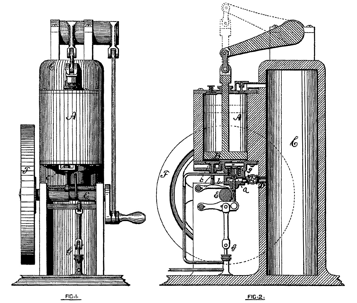
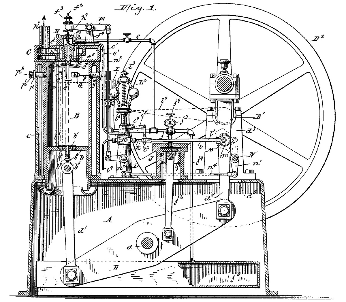
Brayton’s 1874 patent illustrating a double-sided piston. The upper side of piston B compressed air as the lower side was exposed to the combustion process of air and fuel being mixed and ignited in chamber H. Reservoir C only stored compressed air.

Brayton’s experience with steam engines and how steam expands into the cylinder to smoothly act on the piston probably influenced his desire to have the fuel burn in the cylinder. Gas expansion created by burning fuel acts smoothly on the piston, whereas the sudden ignition of fuel by a spark creates more of an explosion that exposes the piston and other engine components to high stresses. The combustion (motor) cylinder was about twice the volume of the compression (pump) cylinder, and the reservoir was no more than twice the volume of the combustion cylinder. The pressure in the reservoir was always greater than the pressure in the combustion cylinder. A water jacket surrounded the combustion cylinder to provide engine cooling.

While the 1872 patent illustrated an engine utilizing a separate compression piston, Brayton explained in the patent that the same principles of his engine could be applied utilizing both sides of the same piston. One side of the piston would compress the working fluid, while the other side of the piston would be driven by the expanding gases as the working fluid undergoes combustion. The patent drawing also shows a flywheel mounted to the camshaft. Engine power would be distributed from a driving pulley on the opposite end of the flywheel. However, images of early Brayton engines show an articulated rod mounted to the connecting rod that drove the flywheel and drive pulley.

brayton-vertical-ready-motor-engine

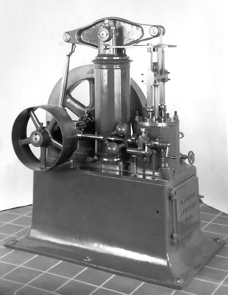
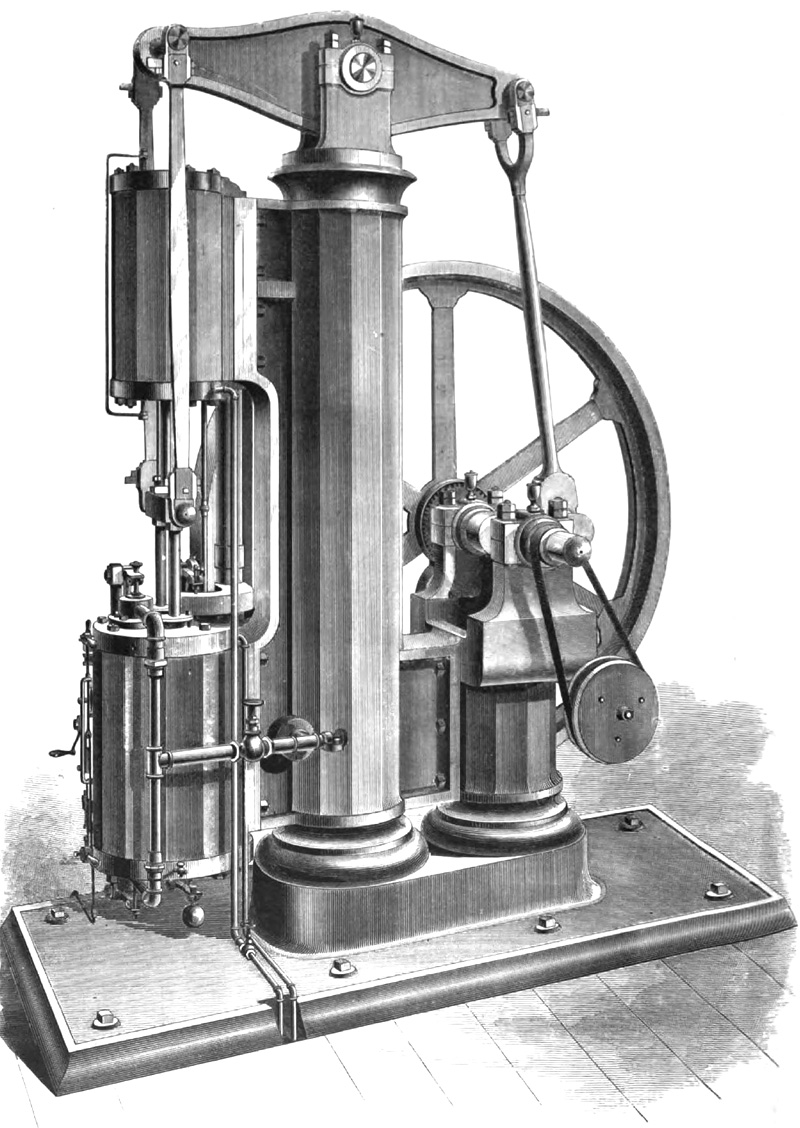
Brayton Ready Motor vertical engine with a double-sided piston. The air reservoir was housed in the rocking beam support column. Note the ball governor.

Around 1873, Brayton installed a 4 hp (3.0 kW) engine in a streetcar in Providence, Rhode Island. The streetcar could obtain a speed of 15 mph (24 km/h), but it would barely move with a full load and had difficulty climbing an incline. A larger 12 hp (8.9 kW) engine was substituted, as it was the most powerful Brayton engine that fit in the space available. The engine took up the space of one passenger and enabled the streetcar to climb a 5 percent grade. All total, the streetcar was tested for 18 months. However, the tests indicated issues with wheel slip on the rails, especially in snow or ice, and financial issues brought an end to the experiment.

A drawback to the 1872 engine was the storage of the volatile gas mixture in the reservoir. If any flame were to get past the wire gauze and continue to burn back to the reservoir, the contents of the reservoir would explode. A safety valve prevented damage to the engine, but such an event was very disconcerting to anyone near the engine. The use of light, gaseous fuel exacerbated the issue. In 1874, Brayton switched to a heavy petroleum oil fuel and patented a refined engine in which only air was stored in the reservoir. A small supply of petroleum fuel was pumped into absorbent, porous material contained in a chamber that surrounded the induction pipe. The top of the chamber formed what was basically a burner. As the liquid fuel was heated by the engine and vaporized, it joined with the air charge being admitted into the cylinder via a camshaft-driven valve. The mixture was then ignited as it flowed through the burner section and into the cylinder. The burner stayed lit by residual fuel from the absorbent material mixing with a small amount of air from the reservoir that constantly passed through the burner.

brayton-ready-motor-chart

Engine speed was controlled by an admission valve that regulated the amount of air passing into the cylinder. Although the fuel quantity supplied to the chamber was metered and dependent on engine speed, making changes to engine speed proved to be difficult. Any change in the amount of air supplied meant that there was a brief period of either too much or too little fuel, and this would occasionally extinguish the burner flame. By 1876, this issue had been resolved by implementing a new fuel injection process. The incoming air passed through the absorbent, porous material that was saturated with injected fuel. A jet of air coincided with the injection of fuel and helped distribute the fuel throughout the absorbent material. This injection technique proved more responsive than the earlier vaporization process.

Other changes incorporated in the 1874 engine were the use of both sides of the piston. A rod connected to the compression side of the piston extended out of the engine. The rod decreased the volume of the compression cylinder to less than that of the combustion cylinder. The rod also provided a means to harness power from the reciprocating movement of the piston. Although the rod was mounted on the compression side of the double-sided piston, it was the power stroke of the combustion side that provided the motive force.

brayton-1876-inverted-walking-beam-engine

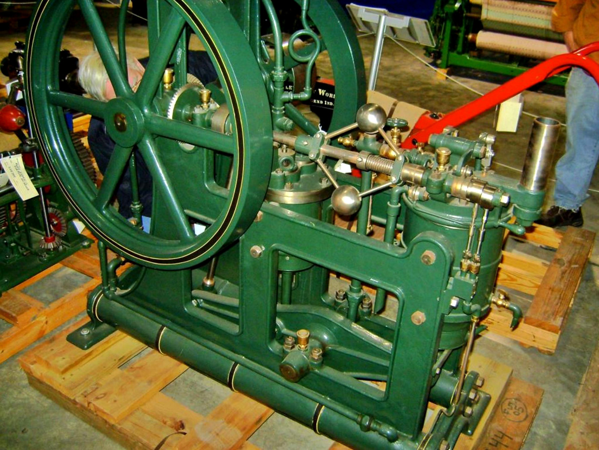
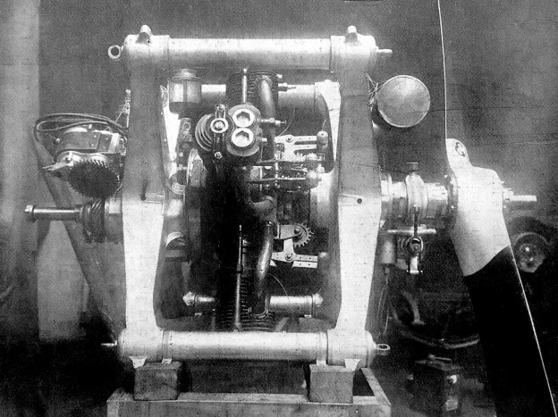
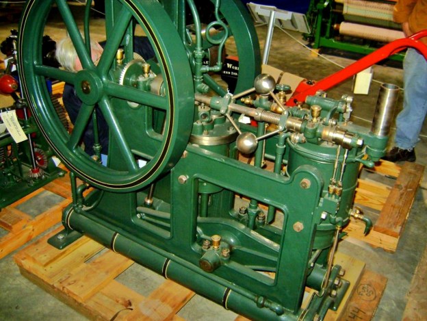
Circa 1876 Brayton inverted rocking beam engine. The combustion cylinder is on the left, and the smaller compression cylinder is at the center of the engine. Two air reservoirs made up the engine’s base; one was used for operating the engine, and the other was used for starting. The engine is currently in storage at the Smithsonian. (Woody Sins image via John Lucas / smokstak.com)

Development of the Brayton Ready Motor continued, and by 1875, the compression cylinder was completely separate from the combustion cylinder. Both cylinders had the same bore, but the stroke of the compression cylinder was about half that of the combustion cylinder. A number of different engine styles, both vertical and horizontal, were built, and the engines used different ways to harness the power of the compression cylinder. Some engines used the compression cylinder to actuate a rocking beam; other engines had the compression cylinder connected to a crankshaft that turned the power wheel.

By 1875 (and possibly as early as 1873), the Pennsylvania Ready Motor Company in Philadelphia had been established to sell Brayton’s engines, but the engines were built in the Exeter Machine Works in Exeter, New Hampshire. The Brayton Ready Motor may have been the first commercially available internal combustion engine. Engines based on the Brayton cycle were also sold by a number of other companies, including the New York & New Jersey Motor Company (by 1877) and Louis Simon & Sons, in Nottingham, England in 1878.

brayton-1876-vertical-engine

Drawing of the 10 hp (7.5 kW) vertical Brayton Ready Motor displayed at the Centennial Exposition in Philadelphia, Pennsylvania in 1876. This is the same engine that inspired George Selden. The compression cylinder was mounted above the combustion cylinder. The column supporting the rocking beam also contained the reservoir.

In 1878, John Holland used a 4 hp (3.0 kW) vertical Brayton engine in the first submarine powered by an internal combustion engine, the Holland I. While functional, this submarine was not a true success. Holland’s second submarine, the Fenian Ram, used a 15 hp (11.2 kW) horizontal Brayton engine and was launched in 1881. This submarine has been preserved and is displayed in the Paterson Museum in Paterson, New Jersey.

Also in 1878, a vertical engine was tested in an omnibus in Pittsburgh, Pennsylvania, but local authorities would not permit its use to transport passengers. Scottish engine pioneer Dugald Clerk converted a 5 hp (3.7 kW) Brayton engine to spark ignition. This engine was the first two-stroke, spark ignition engine ever built. Horizontal engines were installed in a few boats that operated on the Hudson River. In 1880, the USS Tallapoosa was fitted with a Brayton engine capable of 300 rpm. Other Brayton engines were used for industrial purposes such as powering pumps, cotton gins, or grinding mills. These Brayton engines were the first practical oil engines and were noted for their ease of starting and steady operation.

selden-auto-1906

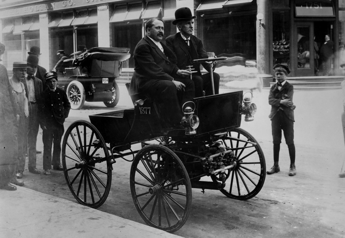
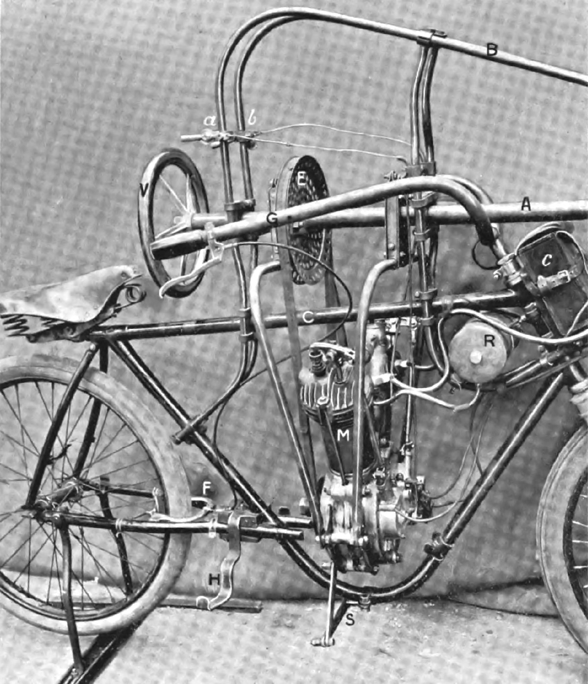
George Selden and Ernest Samuel Partridge in the Selden automobile in 1905. The vehicle was built in 1903 to prove the viability of Selden’s patent design. Between the front wheels is a three-cylinder Brayton-style engine, which ultimately led to Selden’s patent claims being dismissed.

George Selden was inspired by the 10 hp (7.5 kW) Brayton engine he saw at the 1876 Centennial Exposition in Philadelphia and felt the engine could be adapted to power a practical wheeled vehicle (automobile). In 1879, Selden applied for a patent on his three-cylinder Road Engine, which powered a four-wheel carriage. Selden continued to delay his patent with minor modifications until 1895, when the patent was finally granted despite the fact that Selden had never built the actual vehicle. That did not deter Selden from claiming he invented the automobile and demanding royalties from all automobile manufactures—suing those who refused to pay. Henry Ford led the rebellion against Selden and lost the court case in 1909. However, that ruling was overturned on appeal in 1911. For the successful appeal, Ford demonstrated that Selden’s automobile used an engine based on the Brayton cycle (two-stroke and a constant-pressure cycle), while Ford and others used engines based on the design of Nicolaus Otto (Otto cycle: four-stroke and a constant-volume cycle). No automobiles were built with a Brayton cycle engine; therefore, the automobile manufacturers were not infringing on Selden’s patent.

By the late 1880s, it was becoming clear that the Brayton cycle for piston-driven internal combustion engines was outclassed by the more efficient Otto cycle. The main issue facing the Brayton engine was its relatively low pressure (60–80 psi / 4.1–5.5 bar) combined with excessive friction, pumping, and heat losses between the compression and combustion cylinders.

brayton-horizontal-marine-engine

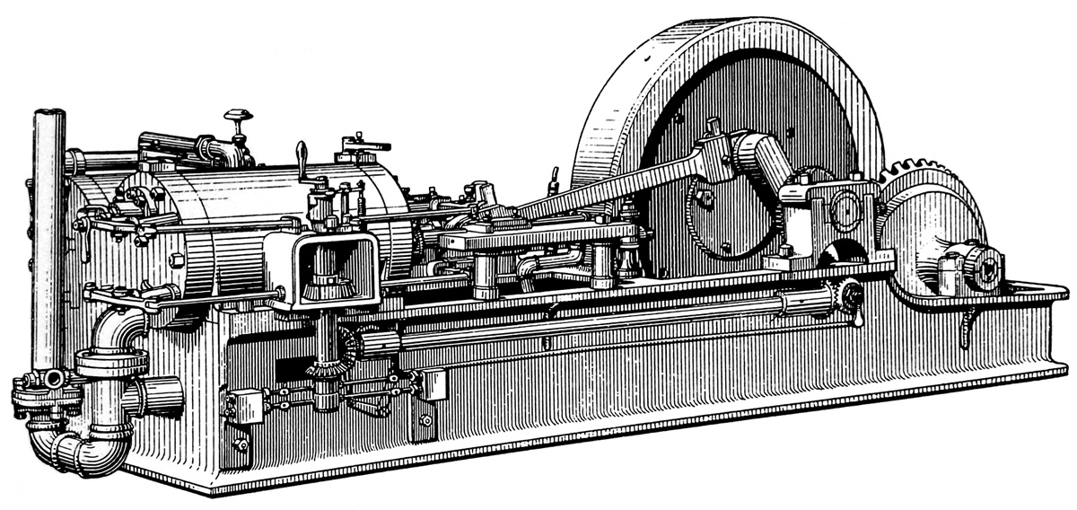
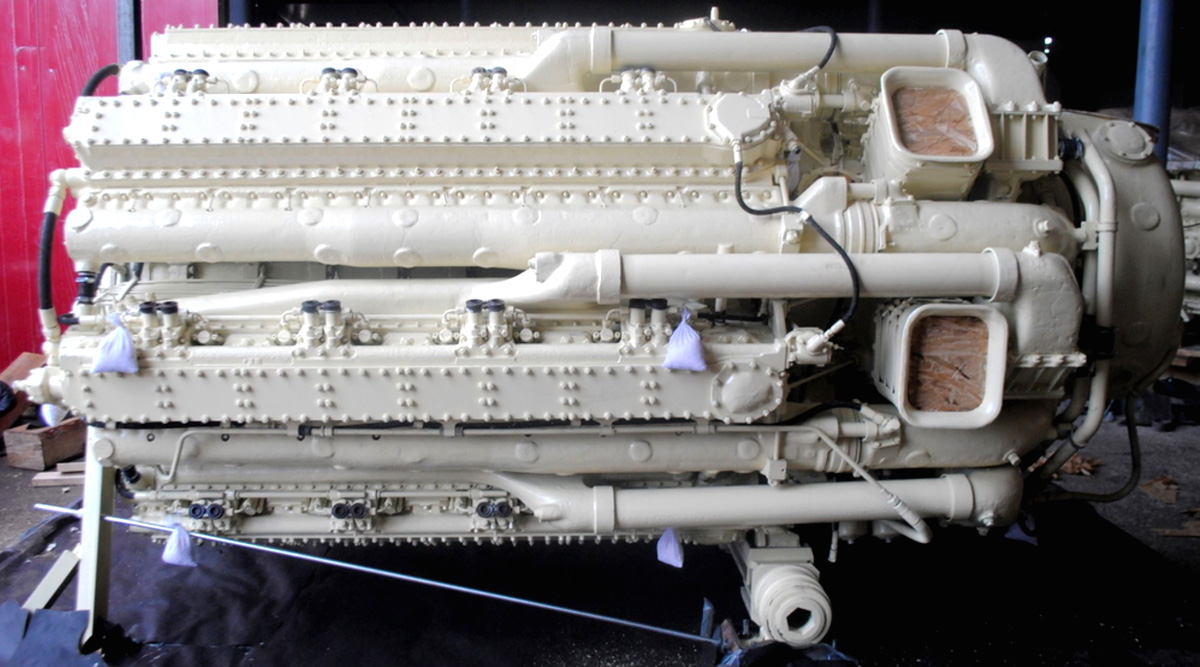
Horizontal Brayton Ready Motor marine engine that was very similar, but not identical, to the engine used in the Fenian Ram submarine. The combustion cylinder is in the foreground, and the compression cylinder is in the background. The bevel gear powered the propeller shaft.

Brayton continued to develop his engine and applied for a patent in 1887 that outlined a horizontal, fuel injected, four-stroke engine. The cylinder was closed at both its combustion (hot) and non-combustion (cool) sides. Exhaust from the hot side of the cylinder passed through a water-cooled condenser that opened to the cool side of the cylinder. As the piston moved up on the exhaust stroke, the vacuum created in the cool side of the cylinder helped draw exhaust gases out of the hot side of the cylinder. An exhaust valve on the cool side of the cylinder was sprung to open at just above atmospheric pressure. As the piston moved toward the cool side of the cylinder on the intake stroke, the exhaust valve opened to expel the products of combustion. When the intake valve was opened, it brought fresh air into the cylinder and sealed the condenser. The intake valve then closed, and the piston moved toward the hot side of the cylinder to compress the air. Brayton stated in his patent that the cylinder’s cycle provided an abundance of fresh air to increase the engine’s power and efficiency.

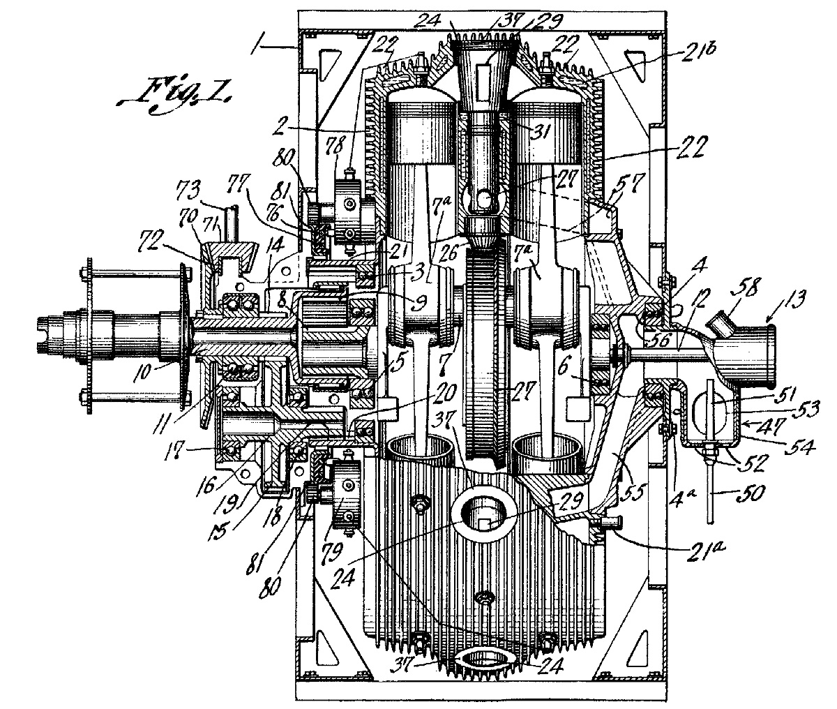
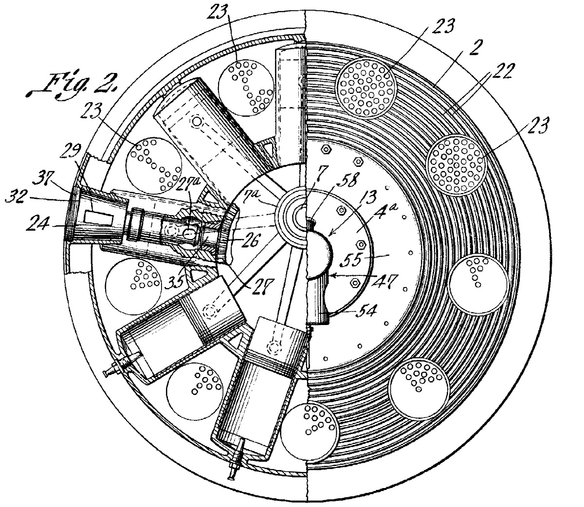
Once the air was compressed, fuel was injected into the cylinder. The act of injecting the petroleum oil under pressure converted the fuel to a fine spray that was easily ignitable. The fuel injection pump was controlled by a follower riding on an engine-driven camshaft, and engine speed was controlled by the quantity of fuel injected. Once injected, the fuel was ignited by an incandescent burner made from a coil of platinum wire. This concept is very similar to a hot bulb in a much later semi-diesel engine. Brayton’s fuel injection was ideally suited for the use of heavy fuels. This engine was built with a 7 in (179 mm) bore and a 10 in (254 mm) stroke, displacing 385 cu in (6.31 L). Running at 200 rpm and driving a 30 in (762 mm) fan at 1,500 rpm for 10 hours, the engine only consumed 3.5 gallons (13.2 L) of kerosene.

brayton-1887-patent-ready-motor-engine

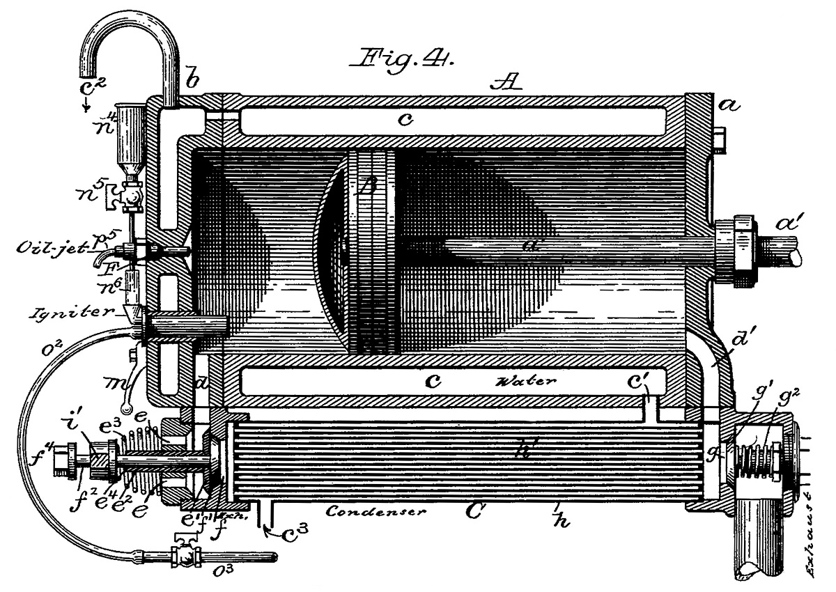
Patent drawing showing the cylinder of Brayton’s horizontal, four-stroke engine of 1887. Passage d was used for both intake and exhaust. Passage d1 harnessed the vacuum created under the piston to help draw the exhaust gases out of the cylinder and through the condenser (C). The exhaust was expelled via valve g1. Fresh air was admitted via valve e1, which sealed the condenser. Fuel was injected via “Oil-jet” F and ignited by a platinum coil.

In 1890, Brayton patented his last engine, a vertical four-stroke that featured fuel injection. As the piston moved down on its intake stroke, a valve in the piston head opened and allowed air from the crankcase to enter the vacuum in the cylinder. As the piston moved up on the compression stroke, the exhaust valve opened for a short time to evacuate any remaining products of combustion. With all valves closed, the remaining air was compressed, and fuel was injected in a combustion chamber space above the piston. A connecting rod attached the piston to an inverted rocking beam, and the opposite end of the rocking beam was connected to a crankshaft. A small air pump was driven from a rod connected to the rocking beam. The air pump provided the pressure for the fuel injection system, enabling a blast of air to disperse the fuel into a fine spray as it was forced into the combustion chamber. The fuel was ignited by an incandescent burner and continued to burn as more fuel was injected and the piston moved down on the power stroke. Brayton’s last engine worked through a similar process as the engines Rudolf Diesel began developing in 1893, but Diesel used much higher cylinder pressures.

While traveling in England and still experimenting with engines, Brayton passed in 1892 at the age of 62. Production of his engines had already decreased by the time of his death but may have continued until the early 1900s. While names like Otto and Diesel are known to many today, Brayton’s is relatively unknown despite his pioneering work. Brayton’s engines were used in land vehicles, boats, and submarines before Otto’s or Diesel’s engines successfully ran. Undoubtedly, Brayton’s engineering contributions helped pave the way for many who followed. Out of the hundreds of Brayton Ready Motors that were made, only around six original engines are known to survive today.

brayton-1890-patent-ready-motor-engine

Patent drawing illustrating Brayton’s 1890 inverted rocking beam (D) engine. Air slightly pressurized in the crankcase (A) passed through a valve (b1) in the piston to fill the cylinder (B). Fuel was injected (via g) and ignited by a burner (G) in a combustion chamber space (B1) at the top of the cylinder. A smaller cylinder (J) acted as a pump to power the fuel injector.

Sources:
– Correspondence with John Lucas
– “Improvement in Gas Engines” US patent 125,166 by George B. Brayton (granted 2 April 1872)
– “Gas Engines” US patent 151,468 by George B. Brayton (granted 2 June 1874)
– “Gas and Air Engine” US patent 432,114 by George B. Brayton (applied 15 September 1887)
– “Hydrocarbon Engine” US patent 432,260 by George B. Brayton (granted 15 July 1890)
Internal Fire by C. Lyle Cummins Jr. (1976/1989)
The Gas and Oil Engine by Dugald Clerk (1904)
A Text-Book on Gas, Oil, and Air Engines by Bryan Donkin Jr (1894)
Pioneers, Engineers, and Scoundrels by Beverley Rae Kimes (2005)
– “The Brayton Ready Motor or Hydrocarbon Engine” Scientific American (13 May 1876)
– “Brayton’s Hydrocarbon Engine” Scientific American Supplement, No. 58 (10 February 1877)
– “Selden Patent Not Infringed” The Automobile (12 January 1911)
– “Road Engine” US patent 549,160 by George B Selden (applied 8 May 1879)
– “Events Which Led Up to the Formation of the American Street Railway Association” by D. F. Longstreet The Street Railway Journal (November 1892)
http://todayinsci.com/B/Brayton_George/BraytonGeorgeBoat.htm
http://todayinsci.com/B/Brayton_George/BraytonGeorgeEngine.htm
http://todayinsci.com/B/Brayton_George/BraytonGeorgeEngine2.htm
http://todayinsci.com/B/Brayton_George/BraytonGeorge.htm
https://www.smokstak.com/forum/showthread.php?t=115633
http://users.zoominternet.net/~pcgray/FenianRam/fenianarticle.htm
http://vintagemachinery.org/mfgindex/imagedetail.aspx?id=6367

mercedes-benz-w154-record-car

Mercedes-Benz W154 Record Car

By William Pearce

For the 1938 European Grand Prix season, the Association Internationale des Automobile Clubs Reconnus (AIACR) issued a rule change that limited the displacement of supercharged engines to 3.0 L (183 cu in) and normally aspirated engines to 4.5 L (275 cu in). Rather than modifying its existing W125 racer with its supercharged 345.6 cu in (5.66 L) straight-eight engine, Mercedes-Benz built an entirely new car for the 1938 season. Designated W154, the car was designed by Rudolf Uhlenhaut, Max Sailer, and Max Wagner.

The 1938 Mercedes-Benz W154 Grand Prix racer. Each of the hand-built cars was unique, and they underwent modifications throughout the 1938 race season. For 1939, the nose of the car was extended and a new grille was installed.

The 1938 Mercedes-Benz W154 Grand Prix racer. Each of the hand-built cars was unique, and they underwent modifications throughout the 1938 race season. For 1939, the nose of the car was extended, and a new grille was installed.

The Mercedes-Benz W154 was an open-wheel, front-engine Grand Prix race car. The W154’s chassis was essentially the same as that used on its predecessor, the W125. The W154 had a 107.4 in (2,728 mm) wheelbase, a 58.0 in (1,473 mm) track for the front wheels, and a 55.6 in (1,412 mm) track for rear wheels. The car’s frame was made of tubular steel and was covered with aluminum body panels contoured to improve aerodynamics.

Powering the W154 was a V-12 engine known as the M154. The M154 engine was designed by Albert Heess and was inspired by the 570 hp (425 kW), 340 cu in (5.58 L) DAB V-12 engine that was intended for the W125 during the 1936 Grand Prix season. The DAB engine made the W125 too heavy for the Grand Prix class, and the engine was replaced by the lighter M125 straight-eight. On 28 January 1938, a tuned DAB engine developing some 736 hp (549 kW) was installed in a special, streamlined W125 chassis. The car and engine combination was known as the Rekordwagen (record car). Driven by Mercedes-Benz driver Rudolf Caracciola, the W125 Rekordwagen set a new Class B (5.001–8.000 L / 305–488 cu in) speed record of 268.863 mph (432.692 km/h) over 1 km (.6 mi) and 268.657 mph (432.361 km/h) over 1 mile (1.6 km).

mercedes-benz-w125-rekordwagen

The W125 Rekordwagen and the DAB V-12 engine were used to set Class B records in 1938. In 1939, a M154 engine was installed, and the car set Class D records in the flying kilometer and mile.

The two cylinder banks of the M154 V-12 engine were set at 60 degrees. Each bank was comprised of two three-cylinder blocks made of steel. The engine used side-by-side connecting rods and a one-piece crankshaft. Mounted to the front of the M154 engine were two Roots-type superchargers. Air entered a carburetor attached to the superchargers at the very front of the engine. The air/fuel mixture was then compressed by the superchargers operating in parallel and flowed through an intake manifold positioned in the Vee of the engine. The superchargers were driven at 1.5 times engine speed and delivered around 20 psi (1.38 bar) of boost.

Each cylinder had two intake and two exhaust valves that were driven by dual overhead camshafts. The M154 engine had a bore of 2.64 in (67 mm), a stroke of 2.76 in (70 mm), and a displacement of 180.7 cu in (2.96 L). The engine’s compression varied from 5.95 to 1 and 6.60 to 1 depending on the desired reliability. The different compression ratios resulted in the engine’s output varying from 433 hp to 474 hp (323 kW to 353 kW) at 8,000 rpm. It was also noted that the superchargers used an additional 160 hp (119 kW) at 8,000 rpm.

mercedes-benz-w154-record-car

This view of the streamlined M154 record-breaker shows the extensive fairings that covered the car’s wheels, suspension, and cockpit sides.

The V-12 engine was angled in the W154’s frame so that the car’s drive shaft extended back along the left side of the driver and to the rear differential. This configuration allowed the driver to be seated next to the driveline and some 4 in (102 mm) lower in the car, which lowered the racer’s center of gravity and improved its aerodynamics and handling. To compensate for the smaller and less-powerful engine compared to the W125, the W154’s gearbox had closer ratio gears with a fifth gear added to maintain top speed. The M154 weighed around 2,161 lb (980 kg) and had a top speed of over 193 mph (310 km/h).

The W154 did very well during the 1938 Grand Prix season, sweeping the top three spots, with two other cars tied for fifth. The car gave Mercedes-Benz driver Rudolf Caracciola his third European Championship title. Some engine and aerodynamic modifications to the W154 were planned for the 1939 season, but before the season got underway, Mercedes-Benz decided to use the W154 to make attempts on the Class D (2.001–3.000 L / 122–183 cu in) standing start speed record.

mercedes-benz-w154-record-front

This low view of the M154’s front illustrates how the fairings wrapped around to the underside of the car. Note the extra space in the front wheel fairings to allow a limited amount of steering. The intake in the nose of the car led directly to the carburetor.

Chassis number 11 of the 15 W154s built was modified by enclosing the wheels and suspension in aerodynamic fairings. The sides of the cockpit were also enclosed by panels; the one on the right side was easily removed for entry into the cockpit. Further streamlining improvements were made to the rest of the body, and unneeded equipment was removed to make the car as light as possible. Overall, 68 lb (31 kg) were shed, reducing the car’s weight to 2,092 lb (949 kg). Since the record runs were brief, the radiator was removed, and an ice tank was installed above the rear axle. Hot coolant from the engine flowed into the tank and melted the ice, and the now-chilled coolant flowed back to the engine. With the radiator removed, an inlet in the nose of the car fed air directly to the engine’s carburetor. The streamlined W154 record car’s engine developed 468 hp (349 kW) at 7,800 rpm.

On 8 February 1939, Caracciola climbed into the streamlined W154 car as it sat on a special section of the Autobahn south of Dessau, Germany. Called the Dessauer Rennstrecke (Dessau Racetrack), this 6.2 mi (10 km) stretch of the Autobahn was specially made for record attempts and was 82 ft (25 m) wide with the median paved over. From a stop, Caracciola and the W154 rocketed down the Autobahn, covering 1 km (.6 mi) in 20.56 seconds and 1 mile (1.6 km) in 28.32 seconds—both times were new Class D records. Unfortunately, the top speed achieved was not recorded, but the times averaged to 108.800 mph (175.097 km/h) over 1 km (.6 mi) and 127.119 mph (204.578 km/h) over 1 mile (1.6 km).

The next day, Caracciola drove the W125 Recordwagen streamliner with a M154 engine installed. The car fell into Class D with the smaller engine and was used to set new records for the flying km and mile. Caracciola traveled 1 km (.6 mi) in 9.04 seconds at 247.449 mph (398.230 km/h) and 1 mile (1.6 km) in 14.50 seconds at 248.276 mph (399.561 km/h).

mercedes-benz-w154-record-start

Rudolf Caracciola sits in the W154 at the start of a record attempt. Swastikas (Hakenkreuz) appeared on the W125 and W154 record cars. Because of its very negative connotations and the fact that the symbol is illegal in present-day Germany, the swastika markings have been removed from most images.

Not entirely satisfied with the standing start record in the special W154 car, Caracciola set another record on 14 February when he covered 1 km (.6 mi) in 20.29 seconds, averaging 110.248 mph (177.427 km/h). This was the last speed record set in Germany before World War II. The Mercedes-Benz T80 was to make an attempt on the world speed record in 1940, but the war derailed those plans.

The W154’s engine was modified for the 1939 Grand Prix season. The new engine was known as the M163 and used two-stage supercharging. Two superchargers were still at the front of the engine, but now they operated in series, with one feeding the other. The superchargers rotated at 1.25 times crankshaft speed. The first supercharger (stage) provided 12 psi (.83 bar) of boost, which was increased to 19 psi (1.31 bar) after the second supercharger (stage). While similar boost was achieved with the earlier supercharger set up, the two-stage system only consumed 84 hp (63 kW) at 7,500 rpm, about half of the earlier system. This allowed the M163 engine to produce 480 hp (358 kW) at 7,500 rpm. While that was only 6 hp (5 kW) more than the M154 engine, the 500 rpm decrease made the M163 engine much more reliable than its predecessor. Because of the M163 engine, the 1939 cars are often referred to as W163s, but they were still W154s. World War II prevented an official winner of the 1939 Grand Prix season to be declared. However, all the races had been run, and Mercedes-Benz cars occupied the top four spots.

W154 chassis number 11, the one used for the record run, was returned to Grand Prix racer configuration. In 1951, the car was raced by Juan Manuel Fangio in two Grand Prix races in Argentina. The car was preserved and is owned by Mercedes-Benz.

mercedes-benz-w154-record-run

A small amount of tire smoke and dust can be seen near the crowd as the M154 sets off to set standing start records in the 1 km (.6 mi) and 1 mile (1.6 km) distances. The runs were made on a special section of the Autobahn south of Dessau. Note how the overpass does not have any center supports and that the median is paved over. These features gave record challengers more space to operate.

Sources:
The Mercedes-Benz Racing Cars by Karl Ludvigsen (1971)
Classic Racing Engines by Karl Ludvigsen (2001)
http://www.kolumbus.fi/leif.snellman/reco.htm
http://www.ultimatecarpage.com/spec/361/Mercedes-Benz-W154.html
https://en.wikipedia.org/wiki/Mercedes-Benz_W154
http://www.ultimatecarpage.com/car/361/Mercedes-Benz-W154.html
https://en.wikipedia.org/wiki/Mercedes-Benz_W125_Rekordwagen
http://www.ultimatecarpage.com/spec/965/Mercedes-Benz-W125.html
https://en.wikipedia.org/wiki/Mercedes-Benz_W125

pander-s4-engine-run

Pander S.4 Postjager Trimotor Mailplane

By William Pearce

In the early 1930s, Dutch pilot Dirk Asjes was disappointed with the slow development of Dutch airmail flights and Fokker aircraft. Asjes sketched out an aircraft design and asked the aircraft manufacturer Pander to build a special mailplane to compete with KLM (Koninklijke Luchtvaart Maatschappij or Royal Dutch Airlines) mail and passenger service. Officially, Pander was called the Nederlandse Fabriek van Vliegtuigen H. Pander & Zonen (H. Pander & Son Dutch Aircraft Company). Pander was a furniture company that had expanded to aircraft construction in 1924 when its owner, Harmen Pander, purchased the bankrupt VIH (Vliegtuig Industrie Holland or Holland Aircraft Industry).

pander-s4-engine-run

The Pander S.4 Postjager displays its clean lines. The trimotor aircraft was purpose-built as a mail carrier to fly from Amsterdam to Batavia.

Airmail service to the Dutch East Indies involved using the relatively slow Fokker F.XVIII, which had a top speed of 149 mph (240 km/h). To improve service, KLM ordered the Fokker F.XX Zilvermeeuw, which had a top speed of 190 mph (305 km/h). While the F.XX was being built, Pander took up the challenge to build a faster aircraft solely to transport mail. Pander’s new design was the S.4 Postjager, and financial support came from a few Dutch shipping companies who hoped to break KLM’s monopoly on air transport to the East Indies.

The Pander S.4 Postjager was designed by Theodorus (Theo) Slot, who was originally with VIH. The aircraft was a low-wing trimotor with retractable main gear. The S.4 was made almost entirely of wood. The aircraft was powered by three 420 hp (313 kW) Wright Whirlwind R-975 engines. The aircraft’s interior was divided into three compartments: cockpit, radio room, and mail cargo hold.

pander-s4-takeoff

On paper, the S.4 appeared to be an impressive, purpose-built aircraft that could improve airmail service for the Netherlands. In practice, the aircraft never had an opportunity to fully demonstrate its capabilities without outside difficulties hindering its performance.

The S.4 used external ailerons that mounted above the wings’ trailing edge. Sometimes called “park bench” ailerons because of their appearance, they are often mistaken for Flettner tabs. A Flettner tab is a supplementary control surface that attaches to and assists the primary control surface. By contrast, a “park bench” aileron is the primary control surface, and there is no other control surface integral with the wing. External ailerons operated in the undisturbed airflow apart from the wing and were more responsive during minor control inputs or during slow flight. In addition, external ailerons allowed the use of full-span flaps to give the aircraft a low landing speed. However, external ailerons had a tendency to flutter at higher speeds, potentially causing catastrophic damage to the aircraft (but flutter was not well understood in the 1930s). On the S.4, the flaps extended from the engine nacelles to near the wingtips.

The S.4 had a wingspan of 54 ft 6 in (16.6 m) and was 41 ft (12.5 m) long. The aircraft had a maximum speed of 224 mph (360 km/h), a cruising speed of 186 mph (300 km/h), and a landing speed of 60 mph (97 km/h). The S.4 was designed to carry 1,102 lb (500 kg) of mail. It had an empty weight of around 6,669 lb (3,025 kg) and a loaded weight of around 12,125 lb (5,200 kg). Six fuel tanks, three in each wing, carried a total of 555 gallons (2,100 L). The aircraft had a range of 1,510 miles (2,430 km) and a ceiling of 17,717 ft (5,400 m).

pander-s4-underside

This underside view of the S.4 shows its PH-OST registration. Also visible are the external ailerons attached to the wings’ upper surfaces. The aircraft’s slot flaps (not visible) extended from the engine nacelle to near the wingtip.

Cleverly registered as PH-OST, the completed S.4 mailplane made its public debut on 23 September 1933. The Fokker F.XX also made its debut at the event, which was attended by Prince Henry of the Netherlands. The S.4 flew the following month, when Gerrit Geijsendorffer and Funker van Straaten made the maiden flight on 6 October 1933. Flight testing went well, and on 9 December 1933, the S.4 departed on an 8,700-mile (14,000-km) flight from Amsterdam to Batavia (now Jakarta, Indonesia). Flown by Geijsendorffer, Asjes, and van Straaten, this flight was a special run to demonstrate the aircraft’s speed and range and also to deliver 596 lb (270 kg) of Christmas mail (made up of some 51,000 letters and postcards) to the Dutch colony. At the time, the Fokker F.XX was being prepared for the same flight.

The S.4 had made a scheduled stopover in Rome, Italy and was proceeding to Athens, Greece when the right engine lost oil pressure. The aircraft made an emergency landing in Grottaglie, Italy, and inspection revealed that the right engine needed to be replaced. With no engines available anywhere in Europe, one was shipped from the United States and set to arrive on 22 December. This setback put the Christmas mail service in jeopardy. To make sure the mail was delivered, arrangements were made for the F.XX to pick up the S.4’s mail and continue to Batavia. But, the F.XX had its own engine issues before it even took off. This left the Fokker F.XVIII, the aircraft the S.4 and F.XX were meant to replace, as the only alternative. A F.XVIII picked up the mail and continued to Batavia with enough time for Christmas delivery. The failed Christmas flight was a huge embarrassment for both the S.4 and F.XX programs.

pander-s4-ground-side

This side view of the S.4, now named Panderjager, shows the aircraft as it appeared in the MacRobertson Race. Note the “park bench” aileron extending above the wing.

The repaired S.4 set out for Batavia on 27 December and arrived on 31 December. It made the return flight, leaving Batavia on 5 January 1934 and arriving in Amsterdam on 11 January. Although the S.4 averaged 181 mph (291 km/h) on the flight from Batavia, the aircraft’s mail flight failed to impress, and the S,4 was not put into service. Pander decided to prepare the aircraft for the MacRobertson Trophy Air Race flown from London to Melbourne, Australia.

The MacRobertson Race started on 20 October 1934 and covered some 11,300 miles (18,200 km). For the race, the S.4 was flown by Geijsendorffer, Asjes, and Pieter Pronk and carried race number 6. The aircraft had been renamed Panderjager, but some referred to it as the Pechjager (“pech” meaning “bad luck” and “breakdown”). After leaving Mildenhall airfield in England, the S.4 arrived in Bagdad, Iraq in third place at the end of the first day of the race. The next day, the aircraft proceeded to Allahabad, India, still in third place. Upon touchdown in Allahabad, the left gear collapsed, resulting in bent left and front propellers and a damaged left cowling and main gear.

pander-s4-rear

This rear view of the S.4 shows the external brace on the horizontal stabilizer and the elevators’ trim tabs. The image also provides a good view of the “park bench” ailerons.

Allahabad did not have the facilities to repair the S.4. Geijsendorffer took the propellers and traveled by train to the KLM depot in Calcutta (now Kolkata), India to make the needed repairs. This delay took the S.4 out of competition, but the decision was made to finish the race. Repairs were completed, and the S.4 was ready to fly on the evening of 26 October 1934. A service vehicle towing a light was positioned across the field from the S.4 to illuminate its path. The S.4’s crew found the light distracting and asked for it to be shut off, as the aircraft could provide its own lighting.

Once the service vehicle’s light was shut off, the S.4 prepared for takeoff. Unfortunately, the crew of the service vehicle misunderstood the instructions. They thought they were to proceed to the S.4 and illuminate the aircraft from behind. As they made their way toward the S.4 in darkness, the aircraft began its takeoff run. At about 99 mph (160 km/h), the S.4’s right wing struck the service vehicle. Fuel spilled from the ruptured wing and quickly ignited as the S.4 skidded 427 ft (130 m) to a stop. Pronk was uninjured, and Geijsendorffer and Asjes escaped with minor burns, but the S.4 was completely destroyed by the fire. The two operators of the service vehicle were severely injured.

Pander planned to convert the S.4 to a scout or bomber after the race and sell it to the military. With the loss of the S.4, there was no aircraft to sell, and Pander was not able to recover its expenses. The company went out of business a short time later.

The S.4 sits at Allahabad, India with bent propellers on its front and left engines. The de Havilland DH 88 Comet “Black Magic” suffered engine trouble, and work to repair its engine was underway as it sat next to the S.4. The S.4 never left Allahabad.

The S.4 sits at Allahabad, India with bent propellers on its front and left engines. The de Havilland DH 88 Comet “Black Magic” suffered engine trouble, and work to repair its engine was underway as it sat next to the S.4. The S.4 never left Allahabad.

Sources:
Nederlandse Vliegtuigen Deel 2 by Theo Wesselink (2014)
Jane’s All the World’s Aircraft 1934 by G. G. Grey (1934)
Blue Wings Orange Skies by Ryan K. Noppen (2016)
– “High-Speed Mail Machine” Flight (7 September 1933)
– “The Aerial Phost” Flight (5 October 1933)
– “Opening of Amsterdam Aero Club’s New Clubhouse” Flight (28 September 1933)
– “The Pander Postjager Pauses” Flight (14 December 1933)
http://www.aviacrash.nl/paginas/panderjager.htm
https://de.wikipedia.org/wiki/Pander_S4
https://en.wikipedia.org/wiki/Pander_%26_Son

kawasaki-ki-64-engine-run

Kawasaki Ki-64 Experimental Fighter

By William Pearce

In the late 1930s, designers at Arsenal de l’Aéronautique in France began working on a new fighter powered by two engines installed in tandem. One engine was positioned in front of the cockpit, and the other engine was behind the cockpit. Each engine drove half of a coaxial contra-rotating propeller. This design was eventually developed into the Arsenal VB 10. Takeo Doi was a Japanese designer at Kawasaki and was aware of Arsenal’s tandem-engine design.

kawasaki-ki-64-hangar

The Kawasaki Ki-64 fighter undergoing gear retraction tests in a hangar in Gifu. Note the exhaust stacks for the front engine and the dorsal air intake scoop for the rear engine.

Doi was also aware of the evaporative cooling system used on the German Heinkel He 100. Japan had sent a delegation to Germany in December 1938 that successfully negotiated the purchase of three He 100 and two He 119 aircraft. The He 100s were delivered to Japan in the summer of 1940.

In 1939, Doi began to contemplate a high-speed fighter for the Imperial Japanese Army Air Force that used tandem engines and evaporative cooling. At the time, the Japanese aircraft industry was more focused on conventional aircraft, and Kawasaki and Doi were busy with designing the Ki-60 and Ki-61 Hien (Swallow, or Allied code name “Tony”) fighters. In October 1940, Kawasaki and Doi received support for the tandem-engine fighter project, which was then designated Ki-64 (Allied code name “Rob”). The aircraft’s design was refined, and a single Ki-64 prototype was ordered on 23 January 1941.

The Kawasaki Ki-64 looked very much like a continuation of the Ki-61 design, and while some of its features were inspired by other aircraft, the Ki-64 was an entirely independent design. The single-seat aircraft had a taildragger configuration and was of all-metal construction. Although designed as a fighter, the Ki-64 was primarily a research aircraft intended to test its unusual engine installation and evaporative cooling system. Proposed armament included one 20 mm cannon installed in each wing and two 12.7 mm machine guns or 20 mm cannons installed in the upper fuselage in front of the cockpit. The armament was never fitted to the prototype.

kawasaki-ki-64-engine-run

The Ki-64 appears to be preparing for an early test flight. The front engine’s intake scoop can be seen just above the exhaust stacks. Note the exhaust stains from the front engine and that the lightning bolt has not yet been painted on the fuselage.

The Ki-64 was powered by a Kawasaki Ha-201 (joint designation [Ha-72]11) engine that was comprised of two Kawasaki Ha-40 inverted V-12 engines coupled to a coaxial contra-rotating propeller. The Ha-40 (joint designation [Ha-60]22) was a licensed-built Daimler-Benz 601A engine and had a 5.91 in (150 mm) bore, a 6.30 in (160 mm) stroke, and a displacement of 2,070 cu in (33.9 L). As installed in the Ki-64, the shaft for the rear engine extended under the pilot’s seat and through the Vee of the front engine to the propeller gearbox. The rear engine drove the front adjustable-pitch propeller of the contra-rotating unit. The front engine drove the rear fixed-pitch propeller. Each set of propellers had three blades that were 9 ft 10 in (3.0 m) in diameter. The Ha-201 displaced a total of 4,141 cu in (67.9 L) and produced 2,350 hp (1,752 kW) at 2,500 rpm for takeoff and 2,200 hp (1,641 kW) at 2,400 rpm at 12,795 ft (3,900 m). Each engine section could operate independently of the other.

The engine sections had separate evaporative cooling systems. Heated water from the engine at 45 psia (3.1 bar) was pumped to a steam separator, where the water pressure dropped to 25 psia (1.7 bar), and about 2% of the water flashed to steam. The steam was then ducted at 16 psia (1.1 bar) through panels in the wings, where it was cooled and condensed back into water. The water then flowed back into the engine. The evaporative cooling system eliminated the drag of a radiator, and this enabled the aircraft to achieve higher speeds. It was believed that battle damage would not be much of a problem for the cooling system. The low pressure of the steam combined with steam’s low density meant that the amount of coolant lost through a puncture would be minimal, and the separate engines and cooling systems helped minimize the risk of a forced landing if damage did render one system ineffective.

The evaporative cooling system for the front engine was housed in the left wing, and the rear engine’s system was housed in the right wing. Each system consisted of two steam separators, an 18.5-gallon (70 L) tank in the wing’s leading edge near the fuselage, four upper and four lower wing condenser panels, an upper and lower condenser section in the outer flap, and a water tank in the fuselage. Sources disagree regarding the size of each fuselage tank, but combined, the tanks held around 52.8 gallons (200 L). Suspended below the right wing was a scoop that held oil coolers for the engines.

kawasaki-ki-64-ground

Another image of the Ki-64 doing a ground run. Note the aircraft’s resemblance to a Ki-61 Hien. Exhaust for the rear engine was collected in a manifold that exited the fuselage just above where the trailing edge of the wing joined the fuselage. That exhaust exit can just barely be discerned in this image.

The Ki-64 had a 44 ft 3 in (13.50 m) wingspan and was 26 ft 2 in (11.03 m) long. The aircraft had a top speed of 435 mph (700 km/h) at 13,123 ft (4,000 m) and 429 mph (690 km/h) at 16,404 ft (5,000 m). The Ki-64 could climb to 16,404 ft (5,000 m) in 5.5 minutes and had a service ceiling of 39,370 ft (12,000 m). Since the wings housed the cooling system, little room was left for fuel tanks. Each wing had a 22-gallon (85 L) fuel tank, and an 82-gallon (310 L) tank was housed in the fuselage; this gave the Ki-64 a 621 mile (1,000 km) range. The aircraft weighed 8,929 lb (4,050 kg) empty and 11,244 lb (5,100 kg) loaded.

While the Ki-64 was being built, a Ki-61 was modified to test the evaporative cooling system. With its radiator removed and evaporative panels added to its wings, the modified Ki-61 first flew in October 1942. Around 35 flights were made before the end of 1943, and they served to develop and refine the cooling system. The aircraft proved the validity of the evaporative cooling system and achieved a speed 25–30 mph (40–48 km/h) in excess of a standard Ki-61. However, the evaporative cooling system did require much more maintenance than a conventional system.

The Ki-64 was completed at Kawasaki’s plant at Gifu Air Field in November 1943. The aircraft underwent ground tests that revealed a number of issues. By December, the issues were resolved enough for flight testing to commence. The aircraft made four successful flights, but the rear engine caught fire on the fifth flight. The pilot was able to make an emergency landing at Kakamigahara, but the rear engine and parts of the rear fuselage and cooling system had been damaged. The Ha-201 engine was sent to Kawasaki’s engine plant in Akashi for overhaul, and the Ki-64 airframe was sent back to Gifu for repairs.

kawasaki-ki-64-in-flight

A poor image, but perhaps the only one, showing the Ki-64 in flight. The lightning bolt has been painted on the fuselage.

The short flying career of the Ki-64 had shown that its cooling system was insufficient. The system worked well for level flight, but it was inadequate for ground running, takeoff, and climb. When the system was overloaded, steam was not condensed back to water and was subsequently vented overboard via a 16 psi (1.1 bar) relief valve. The cooling system lost about 12 gallons (45 L) of water during a rapid climb from takeoff to 18,000 ft (5,500 m). Water freezing within the system, either while in flight or on the ground during cold temperatures, was another concern. Adding an alcohol mixture to the water coolant was a possible solution, but the Ki-64 never underwent any cold weather testing.

While undergoing repairs, the Ki-64 was to be modified and redesignated Ki-64 Kai. The existing propellers would be replaced with fully adjustable and feathering contra-rotating propellers, which would make it easier for one engine to be shut down in flight. The engines were to be replaced with more powerful Ha-140s (joint designation [Ha-60]41), each of which was capable of 1,500 hp (1,119kW). The coupled engine was designated Ha-321 (joint designation [Ha-72]21) and produced 2,800 hp (2,088 kW). With the changes, it was estimated that the Ki-64 Kai would have a top speed of 497 mph (800 km/h). However, the propeller and engines were delayed by more pressing war-time work, and the Ki-64 program was cancelled in mid-1944.

The Ki-64 airframe remained at Gifu where it was captured by American forces in 1945. Various parts of the cooling system were removed from the aircraft and shipped to Wright Field in Dayton, Ohio for further analysis and testing. The remainder of the Ki-64 was eventually scrapped.

kawasaki-ki-64-at-gifu

The K-64 as discovered by American forces at the end of World War II. The engines had been removed, and the aircraft was in a rather poor state. Note the canopy frame sitting on the wing.

Sources:
Japanese Army Fighters Part 1 by William Green and Gordon Swanborough (1977)
Japanese KI-64 Single Fighter with Two Engines in Tandem and Vapor-Phase Cooling, Air Technical Intelligence Review Report No. F-IR-100-RE by Petaja and Gilmore (31 July 1946)
Japanese Secret Projects by Edwin M. Dyer III (2009)
Japanese Aircraft of the Pacific War by René J. Francillon (1979/2000)
Encyclopedia of Japanese Aircraft 1900–1945 Vol. 4: Kawasaki by Tadashi Nozawa (1966)
The Xplanes of Imperial Japanese Army & Navy 1924–45 by Shigeru Nohara (1999)
Heinkel He 100 by Erwin Hood (2007)

tips-1917-18-cylinder-rotary-engine

Tips Aero Motor Rotary Aircraft Engines

By William Pearce

From a very early age, Maurice A. Tips and his younger brother Ernest Oscar were interested in aviation. By 1909, the Belgian siblings had built their first aircraft: a canard-design, pusher biplane. The first engine installed in the aircraft proved underpowered and was replaced with a Gnome rotary. The engine was geared to two shafts, each driving a two-blade pusher propeller. Although the aircraft made some flights, its handling was unsatisfactory, and the design was not developed further. The aircraft did possess unique concepts, a theme continued in Maurice’s subsequent designs.

tips-1908-biplane

Rear view of Maurice and Ernest Oscar Tips’ 1909 biplane pusher. The aircraft was unable to fly with its original Pipe V-8 engine, but the lighter Gnome rotary enabled the aircraft to takeoff. Note the central gearbox that provided power to the shafts that turned the propellers via right-angle drives.

After the 1909 aircraft, Maurice refocused his efforts on aircraft engines. By 1911, Maurice had designed the first in a series of “valveless” rotary engines. All of Tips’ engines used a rotary valve system for cylinder intake and exhaust. Unfortunately, documentation on these engines is nearly non-existent; their exact order of development and specifications are not known with certainty.

tips-1912-7-cylinder-rotary-engine

Drawings of the 25 hp (19 kW) Tips engine of 1912. Air was drawn through the rotating suction tubes (5) which enable the intake port (14) and exhaust port (13) to align with the cylinder. The suction tubes were geared (9 and 10) to the stationary crankshaft (4).

The first engine was a seven-cylinder rotary that produced 25 hp (19 kW). The engine had a 2.76 in (70 mm) bore, a 4.33 in (110 mm) stroke, and a displacement of 181 cu in (3.0 L). Hollow “suction tubes” took the air/fuel mixture from the engine’s crankcase and delivered it to the cylinders. Each suction tube was geared to the engine’s fixed crankshaft. The suction tubes would spin at half the speed of the crankcase as it rotated. The top of the suction tube had two passageways. Each passageway would align with a common port near the top of the cylinder once every two revolutions of the crankcase. One passageway aligned to allow the air/fuel mixture to flow from the suction tube and into the cylinder. The second passageway aligned to allow the exhaust gases to flow from the cylinder out into the atmosphere.

The 25 hp (19 kW) Tips “valveless” rotary engine was installed in a monoplane built by Henri Gérard. It appears the aircraft was completed around 1913. However, the performance results of the engine and aircraft have not been found. As history unfolded, this was the only Tips engine installed in an aircraft.

Maurice and EO Tips Gerard monoplane

Henri Gérard and his mechanic by Gérard’s Tips-powered monoplane. The engine was a 25 hp (19 kW) seven-cylinder “valveless” rotary. Note the spark plug protruding from the top of each cylinder. (Tips Family Archive via Vincent Jacobs)

Maurice continuously refined the design of “valveless” rotary engines. In late 1912, two larger versions of the seven-cylinder engine were planned. A 50 hp (37 kW) version had a 4.33 in (110 mm) bore, a 4.72 in (120 mm) stroke, and a displacement of 487 cu in (8.0 L). The largest engine produced 70 hp (52 kW) and had a 4.41 in (112 mm) bore, a 5.12 in (130 mm) stroke, and a displacement of 547 cu in (9.0 L). An advertisement stated that all three engines would be displayed at the Salon de l’Automobile held in Brussels, Belgium in January 1913. In addition, the 25 hp (19 kW) engine was used to power a Tips airboat that was displayed at the show.

Engine development continued throughout 1913 and 1914. The most obvious change was that the suction tube was moved to be parallel with the cylinder, rather than at an angle as seen in the earlier engines. The newer engine design had an updated drive for the suction tubes, and the air/fuel mixture no longer passed through the crankcase; rather, it was delivered through a hollow extension of the crankshaft to a space under the suction tubes. A nine-cylinder engine of this design was built, but it is not clear if the engine was built in Europe or the United States; it was most likely built in the US.

tips-1913-and-1914-rotary-engines

The 1913 (left) and 1914 (right) versions of the Tips rotary engine. The major changes were to the suction tube drive and rotary valve. The small tube (no. 14 on the 1913 engine and no. 40 on the 1914 engine) in the stationary crankshaft extension provided oil to the crankshaft and connecting rod.

When World War I broke out, Maurice and Ernest Tips fled Belgium. Ernest made his way to Britain, where he worked with Charles Richard Fairey and helped start the Fairey Aviation Company in 1915. Ernest would return to Belgium in 1931 to start the Fairey subsidiary, Avions Fairey. He also produced the Tipsy series of light aircraft.

Maurice Tips traveled to the US in October 1915 and continued to design aircraft engines. It is quite possible that the nine-cylinder engine was built once Tips had established himself in the US. The engine had a 4.92 in (125 mm) bore and a 5.91 in (150 mm) stroke. It displaced 1,011 cu in (16.6 L) and produced 110 hp (82 kW). The nine-cylinder engine was approximately 35 in (.89 m) in diameter and weighed 290 lb (132 kg). A smaller nine-cylinder engine was designed, but it is not clear if it was built. The smaller engine had a 4.92 in (125 mm) bore and a 5.51 in (140 mm) stroke. It displaced 944 cu in (15.5 L) and produced 100 hp (75 kW).

Tips 9-cylinder rear

Rear view of the 110 hp (82 kW) nine-cylinder Tips “valveless” rotary engine. Air was drawn in through the hollow extension to the crankshaft where it mixed with fuel. Ports in the crankshaft extension led to a distribution chamber at the back of the engine. The air/fuel mixture was drawn into the suction tube behind each cylinder and then into the combustion chamber. (Tips Family Archive via Vincent Jacobs)

For more power, Maurice had the idea of coupling two 110 hp (82 kW) nine-cylinder engines in tandem to make an 18-cyinder power unit. The two engine sections would be placed front-to-front and rotate in the same direction. The engines would be suspended some 20 in (508 mm) below the propeller shaft. A Renold Silent (inverted tooth) drive chain positioned between the two engines would deliver power to the propeller shaft. By varying the size of the drives, a propeller speed reduction could be achieved. Drawings show a 5 in (127 mm) drive gear and a 7.5 in (191 mm) gear on the propeller shaft, which would give a .667 speed reduction. The tandem 18-cylinder engine had an output of 220 hp (164 kW) and was 606 lb (275 kg). The power unit was 62 in (1.57 m) long and 40 in (1.02 m) in diameter, not including the propeller shaft. It is unlikely that a tandem engine was built.

In 1917, The Tips Aero Motor Company was founded in Woonsocket, Rhode Island. That same year, Maurice applied for patents covering his new engine design, which incorporated many concepts from the earlier engines. Rather than a tandem engine, the new Tips engine was a single, 18-cylinder power unit. The rotary engine had two rows of nine cylinders and was housed in a stationary frame. The new engine employed both water and air cooling. The cylinders were arranged in pairs, with one in the front row of the engine and the other in the rear row. The crankshaft had only one throw, and the pistons for both cylinders in a pair were at top dead center on their compression strokes at the same time. The engine’s compression ratio was 5.25 to 1. Each cylinder had one spark plug at the center of its combustion chamber. The spark plugs were fired by two magnetos mounted to the front of the engine and driven from the propeller shaft.

Tips Tandem 18-cylinder engine

The Tips Tandem engine consisted of two nine-cylinder engines coupled together. An inverted tooth chain between the engines delivered power to the propeller shaft. (Tips Family Archive via Vincent Jacobs)

Most rotary engines had a fixed crankshaft and a crankcase that rotated. This arrangement created much stress on the crankshaft and crankcase and also imposed severe gyroscopic effects on the aircraft. The Tips engine employed several unique characteristics to resolve the drawbacks of traditional rotary engines. The crankshaft of the Tips engine rotated and was geared to the propeller shaft. The propeller shaft was geared to the crankcase, which allowed it to rotate in the opposite direction from the crankshaft and propeller. The end result was that when the crankshaft was turning at 1,800 rpm, the propeller would turn at 1,080 rpm, and the crankcase would rotate at 60 rpm in the opposite direction. Rotary engines in which the crankshaft and crankcase rotate in opposite directions and at different speeds are often called bi-directional or differential rotary engines.

The propeller shaft of the Tips 18-cylinder engine was geared to the crankshaft at a .600 reduction; the crankshaft gear had 18 teeth, and the propeller shaft’s internal gear had 30 teeth. For crankcase rotation, the 17 teeth on the propeller shaft gear engaged 51 teeth on one side of a countershaft to give a .333 gear reduction. The other side of the countershaft had 11 teeth that meshed with a 66-tooth internal gear attached to the crankcase and resulted in a further .167 reduction. Having the propeller and crankshaft rotating in opposite directions not only eliminated the gyroscopic effect inherent to conventional rotary engines, but it also neutralized the gyroscopic effect created by the propeller attached to a fixed engine.

tips-1917-18-cylinder-rotary-engine

The 18-cylinder Tips engine of 1917 was far more complex than the earlier engines. Note the paired cylinders separated by the rotary valve (24). The propeller shaft (10) was geared to the crankshaft (7) via reduction gears (8 and 9). The crankcase was geared to the propeller shaft via a countershaft (16).

On the exterior of the cylinder castings were numerous cooling fins. In addition, internal passageways for water cooling were in the cylinder castings. Between each pair of cylinders were a series of air passageways to further augment cooling. The engine did not have a water pump; rather, thermosyphoning and the relatively slow rotation of the crankcase enabled the circulation of cooling water from the internal hot areas of the cylinders out toward the cooling fins on the exterior of the cylinders. The engine’s rotation also aided oil lubrication from the pressure-fed crankshaft to the rest of the engine. The oil pump and carburetor were located on the stationary frame at the rear of the engine.

A flange was positioned on the crankshaft, between the connecting rods of the cylinder pair. Mounted on the flange via ball bearings was an eccentric gear with 124 teeth on its outer edge. Attached (but not fixed) to the crankcase was a master valve gear that had 128 teeth on its inner edge. The gears meshing with an eccentric action resulted in the master valve gear turning four teeth per revolution of the crankshaft. On the outer edge of the master valve gear was a bevel gear with 128 teeth. These teeth engaged a 16-tooth pinion attached to a rotary valve positioned between each cylinder pair. The four teeth per revolution of the master valve gear acting on the 16-tooth rotary valve resulted in the rotary valve turning at a quarter engine speed. Each hollow rotary valve had two intake ports and two exhaust ports.

tips-1917-18-cylinder-valves-and-gear

On the left is the rotary valve shown with the intake ports aligned (Fig 3). The air/fuel mixture entered the valve through ports in its lower end (27a). On the right is the valve with the exhaust ports aligned (Fig 5). Fig 4 shows a cross section of the rotary valve with intake ports (28), exhaust ports (29), and passageways for the flow of cooling water (30). Fig 8 shows the valve gear drive. The crankshaft (7) turned an eccentric gear (44) that meshed (42 and 41) with a gear mounted to the crankcase. The result is that a bevel gear (27) engaged a gear screwed to the bottom of the rotary valve (26 on Fig 3) and turned the valve once for every four revolutions of the crankshaft.

Air was drawn in through a carburetor at the rear of the engine. The air/fuel mixture flowed through a manifold bolted to the cylinder casting and into a passageway that led to a chamber around the lower part of the rotary valve. Holes in the valve allowed the air to flow up through its hollow middle and into the cylinder when the intake ports aligned. As the valve rotated, the exhaust ports would align with the cylinder, allowing the gases to escape out the top of the valve head and into the atmosphere. Passageways in the lower part of the rotary valve head brought in cooling water from the cylinder’s water jacket. Water flowed up through the rotary valve and back into the cylinder’s water jacket. The rotary valve was lubricated by graphite pads and held in place by a spiral spring and retaining cap around its upper surface.

The 18-cylinder Tips engine had a 4.5 in (114 mm) bore and a 6.0 in (152 mm) stroke. The engine displaced 1,718 cu in (28.1 L) and produced 480 hp (358 kW) at 1,800 rpm. The Tips engine weighed 850 lb (386 kg). At speed, the engine consumed 22 gallons (83 L) of fuel and 3 gallons (11 L) of oil per hour. The oil consumption was particularly high, even for a rotary engine, but the Tips engine was larger and more powerful than other rotary engines.

tips-1917-18-cylinder-rear

Rear view of the 480 hp (358 kW) Tips engine shows the extensive fining (22) that covered the engine. The fining and air passages (23) combined to turn the whole engine into a radiator to cool the water that flowed through the engine via thermosyphoning and centrifugal force.

In 1919, the engine was mentioned in a few publications. In 1920, Leo G. Benoit, Technical Manager at Tips Aero Motors, passed away. Benoit was said to be in charge of the engine’s design and construction. No further information regarding the engine and no images of the engine have been found. This lack of information could mean that the 480 hp (358 kW) Tips engine was never built. However, given the detailed description of the engine and that it was worked on from 1917 to at least 1920, the possibility certainly exists that the engine was built and tested.

Sometime before World War II, Maurice Tips returned to Belgium. He continued to design engines and applied for a patent on a rotary piston engine in 1938. This engine was not designed for aircraft use and bore no similarities to his early aircraft engines.

Tips 18-cylinder engine crankcase

Maurice Tips stands next to the unfinished crankcase casting for the 18-cylinder differential rotary engine. The holes in the crankcase’s outer diameter were for the rotary valves. The holes in the crankcase’s face were for water radiators, and the holes inside of the crankcase were for the cylinders. It is not known if a complete engine was built. (Tips Family Archive via Vincent Jacobs)

Sources:
Les Avions Tipsy by Vincent Jacobs (2011)
– “Valveless Rotary Combustion Engine” US Patent 1,051,290 by Maurice Tips (granted 21 January 1913)
– “Improvements in Rotary Combustion Engines” GB Patent 191307778 by Maurice Tips (application 15 April 1913)
– “Improvements in or relating to Rotary Combustion Engines” GB Patent 191506821 by Maurice Tips (application 8 May 1914)
– “Rotary Valve” US Patent 1,286,149 by Maurice A. Tips (granted 26 November 1918)
– “Internal Combustion Engine” US Patent 1,306,035 by Maurice A. Tips (granted 10 June 1919)
– “Valve-Operating Mechanism” US Patent 1,306,036 by Maurice A. Tips (granted 10 June 1919)
– “Internal Combustion Engine” US Patent 2,203,449 by Maurice Tips (granted 4 June 1940)
– “The Tips 480 H.P. Aero Motor” Aerial Age Weekly (17 March 1919)
Airplane Engine Encyclopedia by Glenn Angle (1921)
http://www.vieillestiges.be/fr/rememberbook/contents/42

savoia-marchetti-s65-calshot

Savoia-Marchetti S.65 Schneider Racer

By William Pearce

After the Italian team was defeated on its home turf at Venice, Italy in the 1927 Schneider Trophy Race, the Italian Ministero dell’Aeronautica (Air Ministry) sought to ensure victory for the 1929 race. The Ministero dell’Aeronautica instituted programs to enhance aircraft, engines, and pilot training leading up to the 1929 Schneider race. Early in 1929, the Ministero dell’Aeronautica requested racing aircraft designs from major manufacturers and encouraged unorthodox configurations.

savoia-mrachetti-s65-orig-config

The Savoia-Marchetti S.65 in its original configuration. Note the single strut extending from each float to the tail, the short tail and rudder, and the short windscreen.

Alessandro Marchetti was the chief designer for Savoia-Marchetti and was preoccupied with the design of the long-range S.64 aircraft. Originally, he did not submit a Schneider racer design, but the Ministero dell’Aeronautica encouraged him to reconsider. Soon after, Marchetti submitted the rather unorthodox S.65 design. On 24 March 1928, the Ministero dell’Aeronautica ordered two S.65 aircraft and allocated them the serial numbers MM 101 and MM 102.

The Savoia-Marchetti S.65 was a low-wing, tandem-engine, twin-boom monoplane that utilized two long, narrow floats. The aircraft was designed to incorporate the largest amount of power in the smallest package. The S.65’s tension rod and wire-braced wings were made of wood and almost completely covered with copper surface radiators. The floats were made of wood (some say aluminum), had a relatively flat bottom, and housed the S.65’s fuel tanks. The floats were around 28 ft 8 in (8.75 m) long and were mounted on struts. Originally, one strut extended from the rear of each float to the tail, but a second strut was later added.

savoia-marchetti-s65-2nd-config

The S.65 has been modified with an additional strut extending from each float to the tail. The tail and rudder have also been extended below the horizontal stabilizer. Note that the windscreen has not changed, that the rudder has a rather square lower trailing edge, and that there are no handholds in the wingtips.

A narrow boom extended behind each wing to support the tail. The boom was hollow and had flight cables running through its interior. Sources disagree on whether the booms were made of metal or wood. The horizontal stabilizer was mounted between the ends of the booms. The vertical stabilizer was positioned in the center of the horizontal stabilizer. Originally, the rudder and tail extended only above the horizontal stabilizer, and the rudder was notched to clear the elevator. Later, the tail and rudder were enlarged and extended below the horizontal stabilizer, and the elevator was notched to clear the rudder. The tail and all control surfaces were made of wood and were fabric-covered.

Attached to the wing was a small fuselage nacelle that housed two Isotta Fraschini Asso 1-500 engines. The engines were mounted in a push-pull configuration with one engine in front of the cockpit and the other behind. The nacelle was made of a tubular steel frame and covered with aluminum panels. Oil coolers were mounted on both sides of the cockpit between the engines. Two windows to improve the pilot’s lateral visibility were positioned above each oil cooler. Just behind the front engine was a windscreen for the cockpit. Initially, a short windscreen was installed, but this was later replaced by a longer, more streamlined unit. The fuselage nacelle was around 18 ft (5.48 m) long, including the propeller spinners.

isotta-fraschini-1-500-s65-engine

The 1,050 hp (783 kW) Isotta Fraschini Asso 1-500 engine. It is unclear how much this engine differed internally from a standard Asso 500 engine. The three cantilever mounts and the nearly-flush rear of the engine can clearly be seen. The exhaust ports have been relocated from the outer side of the cylinder head to the Vee side. A water pump and magneto are just visible on the extended gear reduction case. The vertical ribbing on the lower crankcase served to increase its strength.

The S.65’s Asso 1-500 V-12 engines were based on the Asso 500 Ri engine and were heavily modified by Giustino Cattaneo, head engineer at Isotta Fraschini. The engine’s crankcase was ribbed and strengthened to become a structural member of the S.65’s fuselage nacelle. Each engine mounted directly to a steel bulkhead on the end of the cockpit via three cantilever supports. The rear of the engine sat flush with the bulkhead. At the front of the engine was an extended gear reduction case which allowed for a streamlined cowling. Engine accessories, such as the two water pumps and two magnetos, were mounted to the gear case. Each Asso 1-500 engine produced 1,050 hp (783 kW) at 3,000 rpm.

At the bottom of each side of the cowling were two inlets. Air flowed from each inlet into a carburetor and then into three cylinders of the engine. Exhaust ports were located on the Vee side of the engine, and the exhaust gases were expelled up though the top of the cowling. Both engines turned counter-clockwise. Since the rear engine was installed backward, the propellers of each engine turned in opposite directions relative to one another. This installation effectively cancelled out the propeller torque that had been an issue for a number of Schneider racers. The metal, two-blade, fixed pitch propellers had a diameter of approximately 7 ft 5 in (2.26 m). The rear propeller’s spinner was about one-third longer than the front spinner.

savoia-marchetti-s65-calshot

The S.65 as seen at Calshot, England. The long windscreen has now been installed. The lower trailing edge of the rudder is now rounded, and the wingtips now have handholds. This image gives a good view of the surface radiators that cover nearly all of the wings. Also visible is the rectangular cover of the exhaust ports between the cylinder banks.

Italian sources and drawings from Savoia-Marchetti list the S.65 as having a wingspan of 31 ft 2 in (9.5 m) and a length of 35 ft 1 in (10.7 m). However, other sources often cite a wingspan of 33 ft (10.05 m) and a length of 29 ft (8.83 m). It is not entirely clear which figures are correct. The weight of the aircraft was approximately 5,071 lb (2,300 kg) empty and 6,173 lb (2,800 kg) loaded. The top speed of the S.65 was estimated between 375 and 400 mph (600 and 645 km/h).

In mid-1929, Alessandro Passaleva, one of Savoia-Marchetti’s pilots, tested the first S.65 (MM 101) on Lake Maggiore, near the company’s factory in Sesto Calende, Italy. Although the aircraft was not flown, Passaleva recommended a number of changes to stiffen and improve the S.65’s tail. The second S.65 (MM 102) was modified with the additional tail brace and extended rudder and tail. It is doubtful that MM 101 was ever flown or that MM 102 was flown on Lake Maggiore. MM 102 was delivered to the Reparto Alta Velocità (High Speed Unit) at Desenzano on Lake Garda in July 1929.

Initial flight tests of the S.65 were conducted by Tommaso Dal Molin and began in late July 1929. This is most likely the first time an S.65 was flown. Dal Molin was an experienced pilot and also small enough to fit inside the S.65’s very cramped cockpit. Some accounts state that Dal Molin did not bother with a parachute because the cockpit was so small, and the rear propeller made bailing out nearly impossible. A number of issues were encountered with the aircraft’s engines and cooling system. In addition, exhaust fumes constantly entered the cockpit.

savoia-marchetti-s65-calshot-runup

This image shows the S.65’s rear engine being run-up at Calshot. The oil radiator is clearly seen between the two engines, and it gives some perspective as to the small size of the cockpit. Note the various engine accessories mounted to the extended gear reduction case.

It was soon obvious that the S.65 would not be ready in time for the Schneider Trophy Race held on 6–7 September 1929 in Calshot, England. However, the Italians decided to send the aircraft anyway, to give the British team something to consider. Before the S.65 arrived at Calshot, the lower rudder extension was rounded; the longer windscreen was installed, and handholds were added to the wingtips. During the races, the S.65 MM 102 was displayed, and its rear engine was run-up on at least one occasion. Some saw the S.65 as a sign of future high-speed aircraft to come.

Italy had developed four new aircraft for the 1929 Schneider Trophy Race: Macchi M.67, FIAT C.29, Savoia-Marchetti S.65, and Piaggio P.7. The end result was that Italian resources were spread too thin, and none of their aircraft were developed to the point of offering serious competition to the British effort, which was victorious. Once back in Italy, the head of the Reparto Alta Velocità, Mario Bernasconi, decided to recover some pride by making an attempt on the world speed record. Britain had just set a new record on 12 September 1929 at 357.7 mph (575.7 km/h) in its Schneider race-winning Supermarine S6 (N247) piloted by Augustus Orelbar.

savoia-marchetti-s65-dal-molin-calshot

Tommaso Dal Molin poses in front of the S.65. Note the longer windscreen and the side windows just above the oil cooler. Each rectangular port on the cowling leads to a carburetor. Also visible are the louvers that cover the cowling.

The S.65 underwent further refinements in late 1929, and it was believed that the aircraft could exceed the S6’s speed by a reasonable margin. It appears the aircraft was fitted with new aluminum (duralumin), V-bottom floats. In addition, the engine cowling had what appear to be six exhaust ports positioned on each side. Exhaust fumes entering the cockpit was an issue due to the central exhaust location, and relocating the ports to the engine sides (their original location in the Asso 500 engine) would help solve the issue. The carburetor intakes were not changed.

Dal Molin took the S.65 on a test flight from Lake Garda on 17 January 1930 to prepare for his speed record attempt the following day. On 18 January, Dal Molin made three takoff attempts, which were all aborted due to excessive yaw. On the fourth attempt, the S.65 became airborne and then pitched up at an extreme angle. The aircraft stalled some 80 to 165 ft (25 to 50 m) above the water and crashed into the lake. Rescue vessels arrived quickly, but the S.65 with Dal Molin still aboard had quickly sunk 330 ft (100 m) to the bottom of the lake. It was Tommaso Dal Molin’s 28th birthday. A special recovery vessel called the Artigilo retrieved the S.65 on 29 January. Dal Molin’s body was recovered on 30 January. While the exact cause of the crash was never determined, many believe the elevator jammed, resulting in the abrupt pitch up and subsequent stall.

Note: As mentioned above, many sources disagree on various aspects of the S.65. For example, sources (some of which were not used in this article) list the wing spars as being made from four different materials: duralumin, walnut, mahogany, and spruce. While images were closely scrutinized to give an accurate account of the S.65 in this article, only so much can be determined from analyzing a grainy, 85-year-old image. In addition, some sources claim that only one S.65 was built (MM 102). Others say construction of MM 101 was started but never completed, and still others contend that MM 101 was completed and stored at the Reparto Alta Velocità at Lake Garda until 1939.

savoia-mrachetti-s65-recovery

The remains of the S.65 after it was recovered from Lake Garda and placed onboard the Artigilo. The rear engine is in the foreground. Note what appear to be exhaust ports along the sides of the cowling. The aircraft’s fuselage seems to be rather undamaged. Reportedly, the S.65 sank quickly, and some sources claim that Dal Molin could not swim.

Sources:
Schneider Trophy Seaplanes and Flying Boats by Ralph Pegram (2012)
Aeroplani S.I.A.I. 1915–1945 by Giorgio Bignozzi and Roberto Gentilli (1920)
Schneider Trophy Aircraft 1913–1931 by Derek N. James (1981)
MC 72 & Coppa Schneider by Igino Coggi (1984)
L’epopea del reparto alta velocità by Manlio Bendoni (1971)
http://wwwteamgrs-marco.blogspot.com/2015/04/il-recupero-della-salma-del-pilota.html

Zvezda M503 Rear

Yakovlev M-501 and Zvezda M503 and M504 Diesel Engines

By William Pearce

Just after World War II, OKB-500 (Opytno-Konstruktorskoye Byuro-500 or Experimental Design Bureau-500) in Tushino (now part of Moscow), Russia was tasked with building the M-224 engine. The M-224 was the Soviet version of the Junkers Jumo 224 diesel aircraft engine. Many German engineers had been extradited to work on the engine, but the head of OKB-500, Vladimir M. Yakovlev, favored another engine project, designated M-501.

Zvezda M503 front

Front view of a 42-cylinder Zvezda M503 on display at the Technik Museum in Speyer, Germany. Unfortunately, no photos of the Yakovlev M-501 have been found, but the M503 was very similar. Note the large, water-jacketed exhaust manifolds. The intake manifold is visible in the engine Vee closest to the camera. (Stahlkocher image via Wikimedia Commons)

Yakovlev and his team had started the M-501 design in 1946. Yakovlev felt the M-224 took resources away from his engine, and he was able to convince Soviet officials that the M-501 had greater potential. All development on the M-224 was stopped in mid-1948, and the resources were reallocated to the M-501 engine.

The Yakovlev M-501 was a large, water-cooled, diesel, four-stroke, aircraft engine. The 42-cylinder engine was an inline radial configuration consisting of seven cylinder banks positioned around an aluminum crankcase. The crankcase was made up of seven sections bolted together: a front section, five intermediate sections, and a rear accessory section. The crankshaft had six throws and was supported in the crankcase by seven main bearings of the roller type.

Each cylinder bank was made up of six cylinders and was attached to the crankcase by studs. The steel cylinder liners were pressed into the aluminum cylinder block. Each cylinder had two intake and two exhaust valves actuated via roller rockers by a single overhead camshaft. The camshaft for each cylinder bank was driven through bevel gears by a vertical shaft at the rear of the bank. All of the vertical shafts were driven by the crankshaft. The pistons for each row of cylinders were connected to the crankshaft by one master rod and six articulating rods.

Zvezda M503 Rear

Rear view of a M503 on display at Flugausstellung L.+P. Junior in Hermeskeil, Germany. The upper cylinder gives a good view of the exhaust (upper) and intake (lower) manifolds, and the engine’s intake screen can just be seen between the manifolds as they join the compounded turbosupercharger. The exhaust gases exited the top of the turbine housing. (Alf van Beem image via Wikimedia Commons)

Exhaust was taken from the left side of each cylinder bank and fed through a manifold positioned in the upper part of the Vee formed between the cylinder banks. The exhaust flowed through a turbosupercharger positioned at the extreme rear of the engine. Exhaust gases expelled from the turbosupercharger were used to provide 551 lbf (2.45 kN / 250 kg) of jet thrust.

The pressurized intake air from the turbosupercharger was fed into a supercharger positioned between the turbosupercharger and the engine. The single-speed supercharger was geared to the crankshaft via the engine’s accessory section. Air from the supercharger flowed into a separate intake manifold for each cylinder bank. The intake manifold was positioned in the lower part of the Vee, under the exhaust manifold, and connected to the right side of the cylinder bank.

The M-501 had a 6.30 in (160 mm) bore and a 6.69 in (170 mm) stroke. The engine displaced 8,760 cu in (143.6 L) and produced 4,750 hp (3,542 kW) without the turbosupercharger. With the turbosupercharger and the thrust it provided, the engine produced 6,205 hp (4,627 kW). The engine weighed 6,504 lb (2,950 kg) without the turbocharger and 7,496 lb (3,400 kg) with the turbocharger.

Zvezda M503 Bulgaria

This partially disassembled M503 at the Naval Museum in Varna, Bulgaria gives some insight to the inner workings of the engine. The turbine wheel can be seen on the far left. Immediately to the right is the air intake leading to the compressor wheel, which is just barely visible in its housing. From the compressor, the air was sent through the seven outlets to the cylinder banks. The exhaust pipe can just be seen inside the water-jacketed manifold on the upper cylinder bank. Note the studs used to hold the missing cylinder bank. (Михал Орела image via Wikimedia Commons)

By 1952, the M-501 had been completed and had achieved over 6,000 hp (4,474 kW) during tests. The program was cancelled in 1953, as jet and turbine engines were a better solution for large aircraft, and huge piston aircraft engines proved impractical. The M-501 was intended for the four-engine Tupolev 487 and Ilyushin IL-26 and was proposed for the six-engine Tupolev 489. None of these long-range strategic bombers progressed beyond the design phase.

The lack of aeronautical applications did not stop the M-501 engine. A marine version was developed and designated M-501M. The marine engine possessed the same basic characteristics as the aircraft engine, but the crankcase casting were made from steel rather than aluminum. The M-501M was also fitted with a power take off, reversing clutch, and water-jacketed exhaust manifolds.

The exact details of the M-501M’s history have not been found. It appears that Yakovlev was moved to Factory No. 174 (K.E. Voroshilov) to further develop the marine engine design. Factory No. 174 was founded in 1932 and was formerly part of Bolshevik Plant No. 232 (now the GOZ Obukhov Plant) in Leningrad (now St. Petersburg). Factory No. 174 had been involved with diesel marine engines since 1945, and Yakovlev’s move occurred around 1958. Early versions of the marine engine had numerous issues that resulted in frequent breakage. In the 1960s, the engine issues were resolved, and Factory No. 174 was renamed “Zvezda” after the engine’s layout. Many languages refer to radial engines as having a “star” configuration, and “zvezda” is “star” in Russian. Zvezda produced the refined and further developed 42-cylinder marine engine as the M503.

Zvezda M503 cross section

Sectional rear view of a 42-cylinder Zvezda M503. The cylinder banks were numbered clockwise starting with the lower left; bank three had the master connecting rod. Note the angle of the fuel injector in the cylinder and that the injector pumps were driven by the camshaft (as seen on the upper left bank).

The Zvezda M503 retained the M-501’s basic configuration. The engine had a compounded turbosupercharger system with the compressor wheel connected to the crankshaft via three fluid couplings. The compressor wheel shared the same shaft as the exhaust turbine wheel. At low rpm, the exhaust gases did not have the energy needed to power the turbine, so the compressor was powered by the crankshaft. At high rpm, the turbine would power the compressor and create 15.8 psi (1.09 bar) of boost. Excess power was fed back into the engine via the couplings connecting the compressor to the crankshaft. Air was drawn into the turbosupercharger via an inlet positioned between the compressor and turbine.

The M503’s bore, stroke, and displacement were the same as those of the M-501. Its compression ratio was 13 to 1. The M503’s maximum output was 3,943 hp (2,940 kW) at 2,200 rpm, and its maximum continuous output was 3,252 hp (2,425 kW) at the same rpm. The engine was 12.14 ft (3.70 m) long, 5.12 ft (1.56 m) in diameter, and had a dry weight of 12,015 lb (5,450 kg). The M503 had a fuel consumption of .372 lb/hp/h (226 g/kW/h) and a time between overhauls of 1,500 to 3,000 hours.

Zvezda M503 Dragon Fire

Dragon Fire’s heavily modified M503 engine under construction. Each cylinder bank is missing its fuel rail and three six-cylinder magnetos. The turbine wheel has been discarded. The large throttle body on the left has a single butterfly valve and leads to the supercharger compressor. Note that the cylinder barrels and head mounting studs are exposed and that each valve has its own port. (Sascha Mecking image via Building Dragon Fire Google Album Archive)

M503 engines were installed in Soviet Osa-class (Project 205) fast attack missile boats used by a number of countries. Each of these boats had three M503 engines installed. Engines were also installed in other ships. A heavily modified M503 engine is currently used in the German Tractor Pulling Team Dragon Fire. This engine has been converted to spark ignition and uses methanol fuel. Each cylinder has three spark plugs in custom-built cylinder heads. The engine also uses custom-built, exposed, cylinder barrels and a modified supercharger without the turbine. Dragon Fire’s engine produces around 10,000 hp (7,466 kW) at 2,500 rpm and weighs 7,055 lb (3,200 kg).

For more power, Zvezda built the M504 engine, which had seven banks of eight cylinders. Essentially, two additional cylinders were added to each bank of the M503 to create the 56-cylinder M504. The M504 did have a revised compounded turbosupercharging system; air was drawn in through ducts positioned between the engine and compressor. The intake and exhaust manifolds were also modified, and each intake manifold incorporated a built-in aftercooler. At full power, the turbosupercharger generated 20.1 psi (1.39 bar) of boost. The M504 engine displaced 11,681 cu in (191.4 L), produced a maximum output of 5,163 hp (3,850 kW) at 2,000 rpm, and produced a maximum continuous output of 4,928 hp (3,675 kW) at 2,000 rpm. The engine had a length of 14.44 ft (4.40 m), a diameter of 5.48 ft (1.67 m), and a weight of 15,983 lb (7,250 kg). The M504 had a fuel consumption of .368 lb/hp/h (224 g/kW/h) and a time between overhauls of 4,000 hours. The engine was also used in Osa-class missile boats and other ships.

Zvezda M504 56-cyl

The 56-cylinder Zvezda M504 engine’s architecture was very similar to that of the M503, but note the revised turbocharger arrangement. Wood covers have been inserted into the air intakes. Just to the right of the visible intakes are the aftercoolers incorporated into the intake manifolds.

In the 1970s, Zvezda developed a number of different 42- and 56-cylinder engines with the same 6.30 in (160 mm) bore, 6.69 in (170 mm) stroke, and basic configuration as the original Yakovlev M-501. Zvezda’s most powerful single engine was the 56-cylinder M517, which produced 6,370 hp (4,750 kW) at 2,000 rpm. The rest of the M517’s specifications are the same as those of the M504, except for fuel consumption and time between overhauls, which were .378 lb/hp/h (230 g/kW/h) and 2,500 hours.

Zvezda also coupled two 56-cylinder engines together front-to-front with a common gearbox in between to create the M507 (and others) engine. The engine sections could run independently of each other. The 112-cylinder M507 displaced 23,361 cu in (383 L), produced a maximum output of 10,453 hp (7,795 kW) at 2,000 rpm, and produced a maximum continuous output of 9,863 hp (7,355 kW) at the same rpm. The engine was 22.97 ft (7.00 m) long and weighed 37,699 lb (17,100 kg). The M507 had a fuel consumption of .378 lb/hp/h (230 g/kW/h) and a time between overhauls of 3,500 hours for the engines and 6,000 hours for the gearbox.

Zvezda engineer Boris Petrovich felt the 56-cylinder M504 engine could be developed to 7,000 hp (5,220 kW), and the M507 (two coupled M504s) could be developed to over 13,500 hp (10,067 kW). However, gas turbines were overtaking much of the diesel marine engine’s market share. Today, JSC (Joint Stock Company) Zvezda continues to produce, repair, and develop its line of M500 (or ChNSP 16/17) series inline radial engines as well as other engines for marine and industrial use.

Zvezda-M507-engine-korabel

The M507 was comprised of two M504 engines joined by a common gearbox. The engine sections had separate systems and were independent of each other. (www.korabel.ru image)

Sources:
Russian Piston Aero Engines by Vladimir Kotelnikov (2005)
Unflown Wings by Yefim Gordon and Sergey Komissarov (2013)
Ungewöhnliche Motoren by Stefan Zima and Reinhold Ficht (2010)
http://www.propulsionplant.ru/dvigateli/dizelnye-dvigateli/proizvodstvennoe-obedinenie-zvezda/dizeli-tipa-chn1617.html
https://de.wikipedia.org/wiki/Swesda_M503
http://www.zvezda.spb.ru
http://www.shipyard.lv/en/services/engineering/
http://lunohoda.net/forum/viewtopic.php?t=6067
http://www.competitiondiesel.com/forums/showthread.php?t=128242
https://en.wikipedia.org/wiki/Osa-class_missile_boat

Aéro-motocyclette Archdeacon Anzani pose

Archdeacon (Buchet) Aéro-motocyclette

By William Pearce

Ernest Archdeacon was an early proponent of the automobile and aviation. Before 1900, Archdeacon had participated in several automobile races, and he founded the Aéro-Club de France in 1898. In the early 1900s, he sponsored various aviation prizes while he continued to dabble in aviation himself. Undoubtedly, his most bizarre idea was a propeller-driven motorcycle known as the aéro-motocyclette (flying motorcycle).

Aéro-motocyclette Archdeacon Anzani pose

Ernest Archdeacon (middle left) and Alessandro Anzani (middle right) pose with the propeller-driven aéro-motocyclette before Anzani heads down the straight, narrow, tree-lined road behind them.

The aéro-motocyclette was built by the French motorcycle constructor Buchet. The machine consisted of a heavily modified Buchet motorcycle frame and was powered by a two-cylinder, air-cooled Buchet engine. The V-twin engine was made of an aluminum crankcase and had steel cylinders. The Buchet engine had a 2.99 in (76 mm) bore, a 3.15 in (80 mm) stroke, displaced 44 cu in (.726 L), and produced 6 hp (4.5 kW) at 1,800 rpm. The engine was mounted transversely, 90 degrees from the normal position, so that its output shaft pointed toward the rear wheel. A pulley on the output shaft was connected via a belt to a larger pulley on the propeller shaft. The size differential between the two pulleys resulted in a .5 to 1 speed reduction at the propeller shaft; when the engine was turning at 1,800 rpm, the propeller turned at 900 rpm. Most likely, a clutch mechanism was installed on the engine’s output shaft to engage and disengage the belt.

The 59.1 in (1.50 m) long propeller shaft was supported above the handlebars by three ball bearings and extended beyond the front wheel of the aéro-motocyclette. At the end of the propeller shaft was a 57.1 in (1.45 m) diameter, two-blade propeller made of aluminum. To lighten the propeller, numerous small holes were drilled in the blades, which were then covered in parchment (goldbeater’s skin). The propeller’s pitch was 70.9 in (1.80 m). A case attached to the front of the head tube carried the battery ignition for the engine. Ignition controls were originally positioned on the rear support tube of the propeller shaft, but these controls were later either relocated or omitted. The completed aéro-motocyclette weighed 154 lb (70 kg).

Aéro-motocyclette drive

Detailed view of the aéro-motocyclette engine and drive system. The carburetor and fuel tank are in their original positions. The image is labeled as follows: A) propeller shaft; B) propeller shaft support frame; C) motorcycle frame; E) propeller shaft pulley connected to the engine’s output shaft by a V-belt; F) brake; G) handlebars; H) footrest; M) Buchet engine; R) fuel tank (later relocated); S) engine mount; V) starting wheel (later removed); a and b) ignition controls; and c) bag for the battery ignition.

An early version of the aéro-motocyclette had a wheel installed on the end of the propeller shaft nearest the rider. The wheel was used to start the engine; however, the wheel is not present in later photographs of the machine being tested. Most likely, the starting wheel was no longer needed after the clutch mechanism was added to the engine’s output shaft. In addition, the starting wheel spinning inches away from the rider must have been a little disconcerting and probably contributed to the decision to remove it. The carburetor was initially positioned between the cylinders, and a small fuel tank was located just behind the head tube. Later, a different carburetor was installed between the engine and rear wheel, and the fuel tank was repositioned to just in front of the rider’s seat, in the space previously taken up by the starting wheel.

Motorcycle racer Alessandro Anzani was selected to test the aéro-motocyclette. Anzani was born in Italy but had immigrated to France. He worked for Buchet as a motorcycle mechanic and racer, but at the time of testing the aéro-motocyclette, Anzani was in the process leaving Buchet to start his own company. In July 1909, Anzani engines would become famous after powering Louis Blériot’s Type XI aircraft in the first flight across the English Channel.

Aéro-motocyclette Archdeacon Anzani run

Archdeacon supports the aéro-motocyclette as Anzani prepares to start off. This image clearly shows that the starting wheel has been removed from the propeller shaft. In addition, the carburetor has been installed between the engine and rear wheel, and the fuel tank has been relocated in front of the seat. There also appears to be a clutch mechanism installed on the engine’s output shaft.

On 12 (some sources say 11) September 1906, Anzani, Archdeacon, and the aéro-motocyclette converged in Achères (near Paris), France. In the afternoon, Anzani fought to tame the aéro-motocyclette as it raced down a narrow, tree-lined road over a timed 1 km (.62 mi) course. At least two runs were made, the faster of which saw Anzani cover the distance in 45.4 seconds at an average speed of 49.272 mph (79.295 km/h). Anzani noted that the aéro-motocyclette accelerated smoothly and quickly to its top speed.

While the concept of a propeller-driven motorcycle was insane, Archdeacon was not. The aéro-motocyclette was never intended as a marketable form of transportation. Rather, the machine was used to test the efficiency of different types of aircraft propellers. The aéro-motocyclette was built in the summer of 1906, before any powered flight had taken place in Europe. Anzani’s timed and publicized run was intended to demonstrate that a propeller could generate sufficient thrust to enable flight of a heavier-than-air craft. A little over a month after the aéro-motocyclette made its run at almost 50mph (80 km/h), Alberto Santos-Dumont in his Antoinette-powered 14-bis made the first powered flight of a heavier-than-air craft in Europe.

Aéro-motocyclette Archdeacon Anzani

Archdeacon (far left) speaking with Anzani (far right) as two others look on. The small holes in the aluminum propeller are just visible through its parchment covering.

Sources:
– “Les Véhicles à Hélice” by J. H. Aubry, Omnia: Revue Pratique de Locomotion (29 September 1906)
– “Air Propellers as an Aid to Locomotion” The Model Engineer and Electrician (11 October 1906)
– “Archdeacon’s Air-Propelled Motor Bicycle” Scientific American (6 October 1906)
– “Tout à hélice” La Chauffeur (1 October 1906)
Blériot: Herald of an Age by Brain A. Elliot (2000)
https://en.wikipedia.org/wiki/Ernest_Archdeacon
https://fr.wikipedia.org/wiki/Aéromotocyclette

Paradox side

Deissner ‘Paradox’ Rotary Aircraft Engine

By William Pearce

Deissner Paradox running

Charles (Carl) Deissner stands next to the 30 hp (22 kW) Paradox engine during a test run. The frame around the engine enabled it to be run in such demonstrations and was not needed when the engine was installed in an aircraft (which probably never happened). Note the carburetor at the front of the engine.

As early aviators began to take flight, it quickly became apparent that most engines were not suitable for use in aircraft. A number of engineers and designers worked to create light and powerful engines that were ideal for aircraft use. Some of these designs, such as the Antoinette, lay the foundation for many engines to follow, but other engine designs were quickly abandoned. Like many others, Charles (Carl) Deissner of London, England designed one of the engines destined to go nowhere. Deissner called his engine the Paradox.

The Paradox was an air-cooled, four-cylinder, four-stroke, rotary engine. In this context, “rotary” refers to a radial engine in which the crankcase and cylinders rotate around the crankshaft. This is not to be confused with a Wankel engine, which uses a rotor spinning in a fixed crankcase to produce power. Most rotary aircraft engines had the crankshaft fixed to the airframe, while the propeller was attached to and spun with the crankcase. However, the Paradox was not like other rotary engines.

While the crankcase of the Paradox rotated just like any other rotary engine, inside the Paradox, the crankshaft turned at twice the speed of the crankcase and in the same direction. The engine’s internals were kept in order by eccentric gears on the crankshaft engaging ring gears inside the crankcase. The stroke of the crankshaft represented one quarter of the piston’s stroke. The path of the eccentric gear also represented one quarter of the piston’s stroke. The relative motions of the crankcase and crankshaft enabled the full stroke to be utilized and allowed the unique Paradox engine to function.

Paradox engine sectional

Sectional view of the 30 hp (22 kW) Paradox engine. The valves can be seen on the front of the L-head cylinders. Below the valves are the pushrods actuated by counter-weighted rockers. The rockers are driven by a short camshaft extending on each side of a pinion. The pinion rotates as its teeth mesh with a gear fixed to a stationary shaft at the front of the engine.

The easiest way to visualize the Paradox engine’s operation is to consider the piston at the top of the cylinder when the cylinder is at the 12 o’clock position. Here, the crankshaft and its throw are at top dead center. When the engine has rotated 180 degrees, putting the cylinder at the six o’clock position, the crankshaft has rotated 360 degrees. The crankshaft is again at top dead center, but since the cylinder is now at the bottom of the engine, the piston is now at the bottom of the cylinder. When the engine has rotated another 180 degrees, the cylinder is back at the 12 o’clock position, and the crankshaft, having rotated 360 degrees, is again at top dead center, returning the piston to the top of the cylinder.

The crankshaft had two throws 180 degrees apart, and each throw served a pair of cylinders. The cylinders of each pair were 180 degrees apart, and the two cylinder pairs were 90 degrees apart. A non-articulating, solid connecting rod served each cylinder pair so that when one piston was at the top of the cylinder, the piston in the opposite cylinder was at the bottom of the cylinder. Deissner stated that since the connecting rod did not articulate, Paradox engines could be made with relatively long strokes and achieve high compression ratios.

Paradox side

The 30 hp (22 kW) Paradox engine complete with propeller. Note the skew gear-driven magneto, counter-weighted rocker arms, and the cylinders’ L-head design.

Three versions of the Paradox engine were planned for construction with different outputs: 30 hp (22 kW), 70 hp (52 kW), and 100 hp (75 kW). However, it appears only the 30 hp (22 kW) and 70 hp (52 kW) engines were actually built. While both engines had four cylinders and shared the same rotary and eccentric crankshaft arrangement, each engine also had a number of unique features.

The 30 hp (22 kW) Paradox was a demonstration engine mounted in a metal frame. The engine utilized an L-head cylinder with side valves. The single intake and exhaust valves were positioned on the front side of the cylinder. Each valve was actuated by a pushrod driven by a large, counter-weighted rocker arm. Part of the rocker rode on a camshaft that extended through the axis of a pinion. The cam on one side of the pinion controlled the intake while the cam on the other side controlled the exhaust. The pinion was driven by a skew gear mounted on a stationary shaft that did not rotate with the engine.

Induction air was brought in through a carburetor at the front of the engine. The air/fuel mixture then passed through the crankcase, where it was warmed, and into separate manifolds for each cylinder. Exhaust was taken through a manifold from each cylinder, piped through the crankcase, and vented out the front of the engine’s propeller shaft, which was fixed to the crankcase.

Paradox Induction Exhaust

Schematic view of the induction and exhaust system in the 70 hp (52 kW) Paradox engine. For clarity, the valves are illustrated on the front and rear of the T-head cylinder, rather than its sides. Note the offset crankshaft.

A magneto was driven by a skew gear at the rear of the engine. The magneto fired the one spark plug installed in each cylinder. However, it appears the engine could accommodate two spark plugs per cylinder. Ball bearings were used throughout the engine. The 30 hp (22 kW) Paradox engine had a 2.76 in (70 mm) bore and a 7.17 in (182 mm) stroke. The engine displaced 171 cu in (2.8 L). Its 30 hp (22 kW) output was obtained at 1,200 rpm. Increasing the engine’s rpm to 1,400 resulted in an output of 40 hp (30 kW).

The 70 hp (52 kW) Paradox engine also used side valves but in a T-head arrangement, with the valves on opposite sides of the cylinder. The valves were actuated by the same method used on the 30 hp (22 kW) engine, but a pushrod and rocker was now positioned on each side of the cylinder. One schematic shows the valves on the front and back sides of the cylinder, rather than the left and right sides. This was most likely done for illustrative purposes, to show how the engine’s induction and exhaust systems worked. Induction air was brought in the front of the engine, passed through the crankcase (where it was warmed), and flowed through a fixed shaft at the rear of the engine. Here, it passed through a carburetor, and the air/fuel mixture flowed back through the shaft to manifolds at the rear of the engine; these manifolds led to each cylinder. The 70 hp (52 kW) Paradox engine had a 4.0 in (102 mm) bore and a 7.0 in (178 mm) stroke. The engine displaced 352 cu in (5.8 L). Its 70 hp (52 kW) output was obtained at 1,400 rpm, and it produced 60 hp (45 kW) at 1,200 rpm. The engine weighed 220 lb (100 kg).

Deissner Paradox Ad

1910 advertisement for the Paradox engine expressing its many virtues over other rotary engines. The pricing for the 70 hp (52 kW) engine is given, although the 30 hp (22 kW) engine is illustrated in the photograph. The price of the 70 hp (52 kW) engine was increased to £460 in March 1911. (via www.aviationancestry.co.uk)

The 30 hp (22 kW) Paradox engine was running by late 1910. It was run both with and without a 7 ft 6 in (2.3 m) Eta propeller. Some of the engine’s noted advantages were that standard lubricating oil could be used—other rotaries typically needed castor oil. The Paradox engine was also said to have good fuel economy, but no specifics were given. In early 1911, the 30 hp (22 kW) engine broke free during a test run, resulting in a destroyed propeller and a damaged engine. The engine was repaired in February, and the 70 hp (52 kW) Paradox engine was to be finished by March 1911. However, no further information has been found regarding any Paradox engine.

The Paradox engines may have offered some improvements in oil consumption, which was always quite high with standard rotaries, but its other unique features did not offer any tangible advantage over more popular engines. Rotary engines would continue to be widely used until after World War I. At that time, conventional engines had out-powered the rotary, and the inherent limitations of its spinning crankcase design could not be overcome.

Sources:
– “The Paradox Rotary Engine” Flight (19 November 1910)
The Art of Aviation by Robert W. A. Brewer (2nd edition, 1911)
http://www.aviationancestry.co.uk/?companies/&companyName=C.Deissner

Koolhoven FK55 mockup front

Koolhoven FK.55 Fighter

By William Pearce

In November 1936, the Dutch aircraft manufacturer Koolhoven surprised many by bringing a very advanced fighter aircraft mockup to the Paris Salon de l’Aviation (Air Show). Mounted on stands to make it appear suspended in flight, the Koolhoven FK.55 mockup caught everyone’s attention. The impressive mockup was so detailed that anyone who did not study it for a period of time would think that it was a real aircraft. But converting the unique ideas showcased in the mockup into a workable aircraft would pose serious problems for Koolhoven.

Koolhoven FK55 mockup front

The sleek lines of the Koolhoven FK.55 can be seen in this image of the mockup at the 1938 Paris Salon de l’Aviation. Note the machine guns mounted in the wings and the radiators in the aircraft’s nose. The outline of the aircraft’s main gear is just visible under the wings.

The FK.55 was designed by company founder Frederick (Frits) Koolhoven. The mockup was of all wooden construction and featured an aerodynamic fuselage with a somewhat triangular cross section. One corner of the triangle formed the lower part of the fuselage, and the wings extended from the other two (upper) corners. The shoulder-mounted wings were well blended into the fuselage and located just behind the cockpit. The wing center section was built integral with the fuselage.

The FK.55 mockup did not include ailerons. Roll control was to be achieved by slot-spoilers in the outer wing sections. While the “slots” did exist, the “spoilers” were never installed on the mockup, and the slots were covered by aluminum panels. The pivot point of the retractable main landing gear was just off the aircraft’s center line. The legs of the main gear had a bend that allowed them to retract flush into the sides of the fuselage and underside of the wings. At the rear of the aircraft was a non-retractable tail skid.

Koolhoven FK55 mockup gear

The elaborate FK.55 mockup being built at the Koolhoven factory. The very long main gear posed problems when adapted to the prototype.

It is not clear whether or not an engine was actually installed in the mockup. If an engine was installed, it was a Lorraine Pétrel water-cooled V-12 engine installed behind the cockpit and at the aircraft’s center of gravity. A shaft extended from the engine, ran under the pilot’s seat, and connected to a propeller gear reduction unit in the nose of the aircraft. The gear reduction unit enabled the use of contra-rotating propellers. Metal, fixed-pitch propellers were fitted to the prototype.

A cannon could be positioned behind the gear reduction unit and fire through the propeller hub. Each wing had a machine gun installed outside of the propeller arc. Radiators were located on each side of the mockup’s cockpit, between the nose and the wings. Two scoops under the mockup’s fuselage provided air to the engine. The position of the cockpit, forward of the wings and at the very front of the aircraft, provided the pilot an excellent view.

The FK.55 mockup had a 29.5 ft (9.0 m) wingspan and was 27.6 ft (8.4 m) long. The complete aircraft was forecasted to weigh 2,425 lb (1,100 kg) empty and 3,638 lb (1,650 kg) loaded. Estimated performance for the FK.55 included a top speed of 323 mph (520 km/h) at 13,123 ft (4,000 m) and a cruising speed of 280 mph (450 km/h) at the same altitude. The aircraft had an initial rate of climb of 2,983 fpm (15.2 m/s), a service ceiling of 31,496 ft (9,600 m), and a range of 559 mi (900 km).

Koolhoven FK55 mockup

Suspended on stands, the FK.55 mockup was an impressive sight. Note the tail skid and the aluminum covers over the openings for the slot-spoilers.

Back in their factory at Waalhaven Airport in Rotterdam, Netherlands, the Koolhoven team went to work building a flying FK.55 prototype. The aircraft grew wider, longer, heavier, and slower than the original estimates. Each change necessitated another change as the FK.55 prototype came together, and what was once the sleek airframe of the FK.55 mockup eventually resembled a “pregnant duck” (in the words of one Dutch pilot).

The triangular cross section of the mockup’s fuselage had been replaced by a larger, mostly circular form. The wings had lost their blended look and now appeared tacked onto the fuselage. Strength issues with the long and complex landing gear necessitated using fixed gear temporarily attached to the fuselage until the retractable gear issues could be resolved. The front and middle sections of the fuselage were made from welded steel tubing, while the rear section and tail were made from wood. The wings were also made of wood and had split flaps and ailerons. The FK.55 maintained provisions for a 20 mm or 37 mm cannon to fire though the propeller hub, and each wing now housed two machine guns with 500 rpg. However, no armament was installed in the prototype.

Lorraine Petrel and Sterna engine CR props

The Lorraine Pétrel engine (top) and the Sterna (bottom). Note how the front propeller rotates clockwise on the Pétrel but counterclockwise on the Sterna. Roughly translated, the sign under the Sterna reads, “The engine Lorraine Sterna 900 hp; Has offset reducer and double propellers; Dutch Koolhoven FK.55 in flight since 1938.”

There is some disagreement about which engine powered the FK.55 prototype. Most sources state an 860 hp (641 kW) Lorraine Pétrel 12Hars was used, but the 12Hars typically produced around 700 hp (522 kW). Some sources claim a 1,000 hp (746 kW) Lorraine Sterna was used. A 900 hp (671 kW) Sterna with an extension shaft and propeller gear reduction unit was displayed at the Paris Salon de l’Aviation in November 1938. A sign under the engine indicated that it was intended for the FK.55, but it is doubtful that the engine was ever installed in the aircraft, as the FK.55 flew before the 1938 Salon. In images of the FK.55 prototype, the gear reduction unit appears to be the one used with the Pétrel engine. In addition, the front propeller of the Pétrel engine rotated clockwise. The front propeller on both the FK.55 mockup and prototype also rotated clockwise; however, the front propeller of the Sterna engine rotated counterclockwise. Therefore, the Pétrel engine was most likely used, with the Sterna intended to replace it in the near future.

Two two-blade, adjustable-pitch, metal Ratier propellers were installed. The engine’s induction scoops had grown in size and were now positioned on the lower sides of the prototype. The radiators were retained in their original position but had also grown in size, again spoiling the aircraft’s aerodynamics.

The FK.55 prototype had a 31.5 ft (9.60 m) wingspan and was 30.3 ft (9.25 m) long. The complete aircraft weighed 3,527 lb (1,600 kg) empty and 5,027 lb (2,280 kg) loaded. The performance estimates for the FK.55 had been reduced to a top speed of 317 mph (510 km/h) at 11,811 ft (3,600 m) and a cruising speed of 280 mph (450 km/h) at the same altitude. The aircraft had an initial rate of climb of 1,367 fpm (6.9 m/s), a service ceiling of 33,136 ft (10,100 m), and a range of 528 mi (850 km).

Koolhoven FK55 prototype front

The FK.55 prototype was an odd and awkward aircraft, especially when compared to the mockup. Note the fixed landing gear and that the front propeller turned clockwise (when viewed from the rear).

In June 1938, the FK.55 was trucked to Welschap Airfield, a more secluded location for flight testing. The prototype was given the serial number 5501 and had been registered as PH-APB, but the registration was never applied to the aircraft. On the morning of 30 June 1938, Koolhoven pilot Thomas Coppers conducted high-speed taxi tests and hopped the FK.55 into the air on three separate occasions. Later that afternoon, Coppers took the FK.55 into the air for its first flight. Shortly after takeoff, Coppers made a 180 degree turn and quickly landed with the wind. Frits Koolhoven approached the aircraft, where he and Coppers engaged in an animated discussion regarding the FK.55. Some sources state that Coppers had found the cockpit unbearably hot. The taxi test should have given some indication of the heat experienced in the cockpit. Whatever the reason, the FK.55 never flew again.

The FK.55 mockup appeared to be a maneuverable fighter aircraft that afforded the pilot an excellent view, and its contra-rotating propellers eliminated engine torque, making the aircraft manageable for inexperienced pilots. The FK.55 prototype was an odd, ungainly aircraft that was underpowered and incomplete. The Koolhoven team endeavored to rework the FK.55’s design, changing to low wings and a Lorraine Sterna engine of at least 1,100 hp (820 kW), but Frits Koolhoven himself wanted nothing more to do with the aircraft. On 10 May 1940, a German bombing raid struck the Waalhaven Airport. The FK.55 mockup and prototype were destroyed, along with the entire Koolhoven factory, affectively putting an end to the company.

Koolhoven FK55 prototype engine run

When viewed from the side, the FK.55 prototype had a rather “pregnant” appearance. This image illustrates how the pilot was positioned between several heat sources.

Sources:
Jane’s All the World’s Aircraft 1936 by C. G. Grey and Leonard Bridgham (1936)
Jane’s All the World’s Aircraft 1937 by C. G. Grey and Leonard Bridgham (1937)
Jane’s All the World’s Aircraft 1938 by C. G. Grey and Leonard Bridgham (1938)
The Complete Book of Fighters by William Green and Gordon Swanborough (1994)
Koolhoven Vliegtuigen by Theo Wesselink (2012)
Les Moteurs a Pistons Aeronautiques Francais Tome I by Alfred Bodemer and Robert Laugier (1987)