Napier-Railton-completed

Cobb Napier-Railton Endurance Racer

By William Pearce

After John Rhodes Cobb made a small fortune as a fur broker, he started auto racing. Early in Cobb’s racing career, he served as a riding mechanic for Ernest Eldridge and his FIAT Mephistopheles racer, and he occasionally drove John Godfrey Parry-Thomas’ Babs racer on the Brooklands raceway in Surrey, England. In the late 1920s, Cobb had established himself as a capable, gentleman racer at Brooklands. His cars were often serviced by Thomas at his shop, located at the Brooklands raceway. The company was formed by Thomas and Ken Thomson, and renamed Thomson & Taylor in 1927, with Ken Taylor joining the firm after the death of Thomas during a Land Speed Record attempt.

Napier-Railton-Cobb

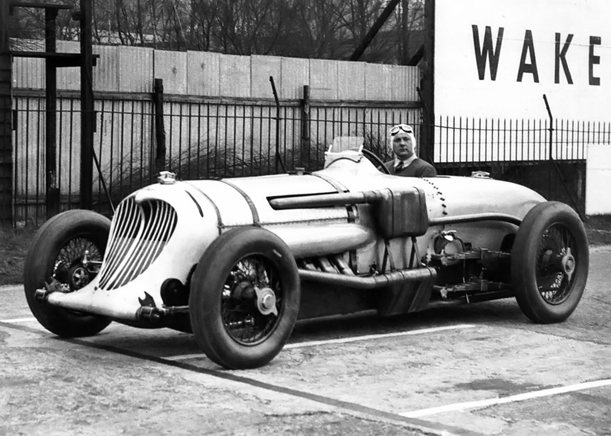
John Cobb sits behind the wheel of the Napier-Railton at the Brooklands track. The exhaust system with mufflers was a requirement for Brooklands and did a good job of muting the engine. Note the vertical bars covering the radiator.

In late 1932, Cobb ordered a special car from Thomson & Taylor that would be able to set lap records at Brooklands as well as establish endurance records up to 24 hours, with sustained speeds in excess of 150 mph (241 km/h). Cobb had previously set the Outer Circuit lap record at Brooklands three times, and it was a record that was special to Cobb. Cobb and Thomson & Taylor gave the task of designing the car to Reid Antony Railton, head engineer. Railton knew he would need to come up with a design that was strong, durable, and reliable to stand up to the rough Brooklands track and the prolonged endurance runs. The car Railton designed would be known as the Napier-Railton.

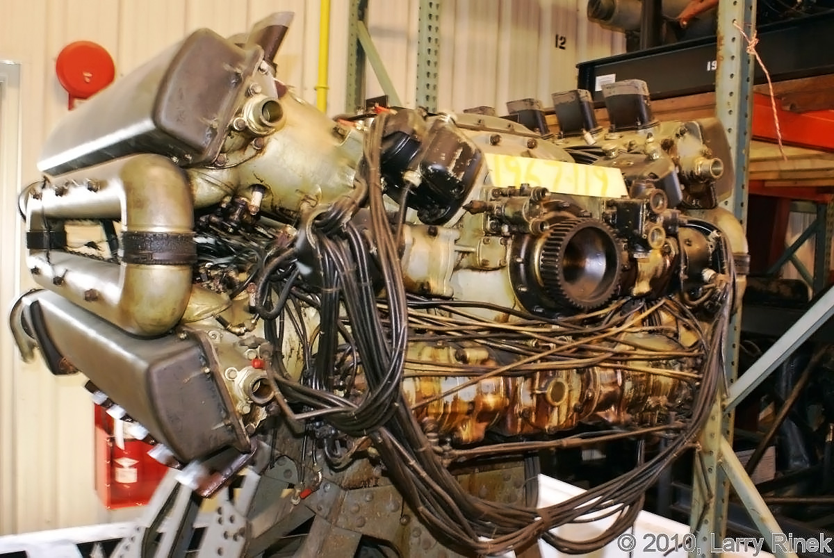
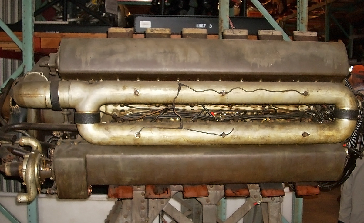
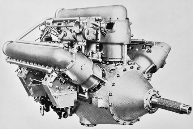
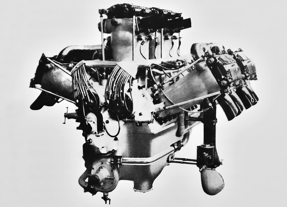
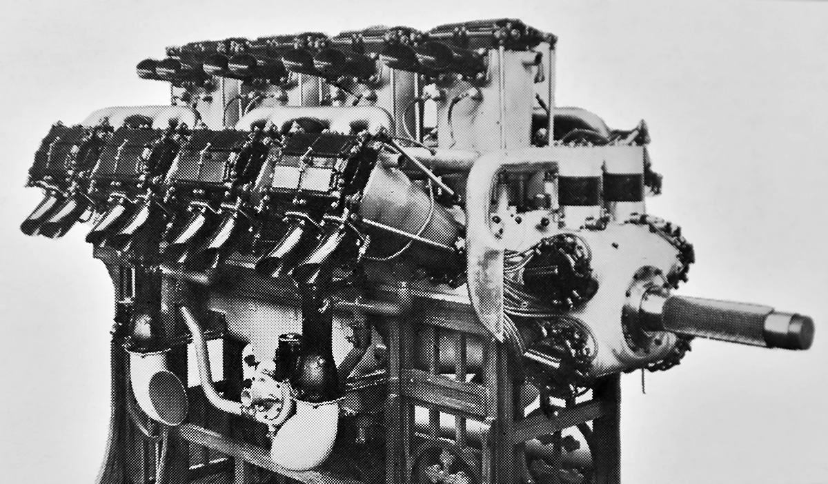
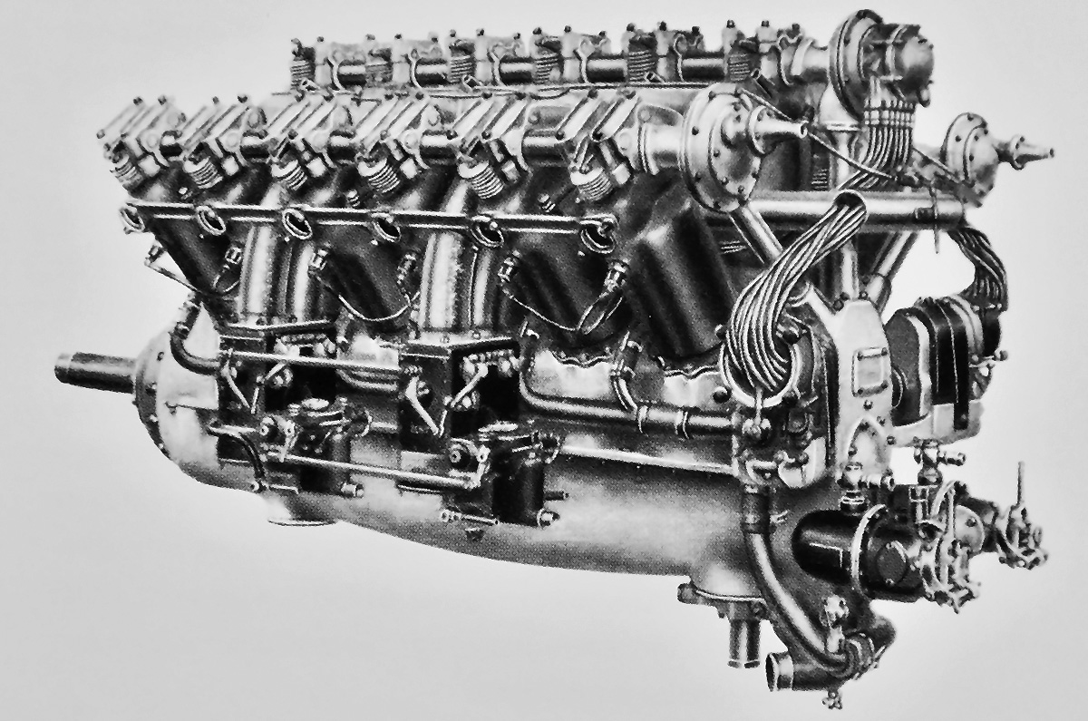
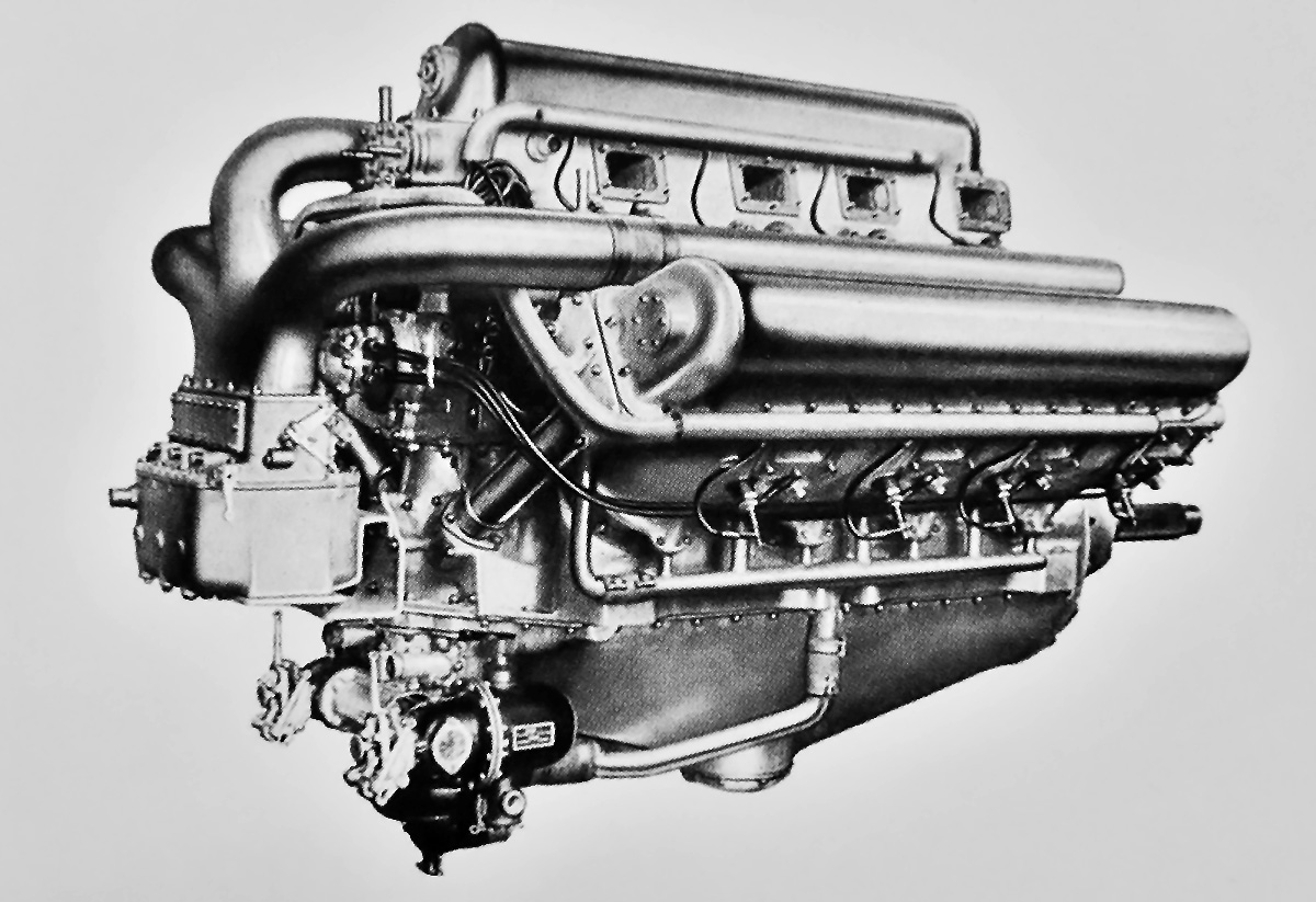
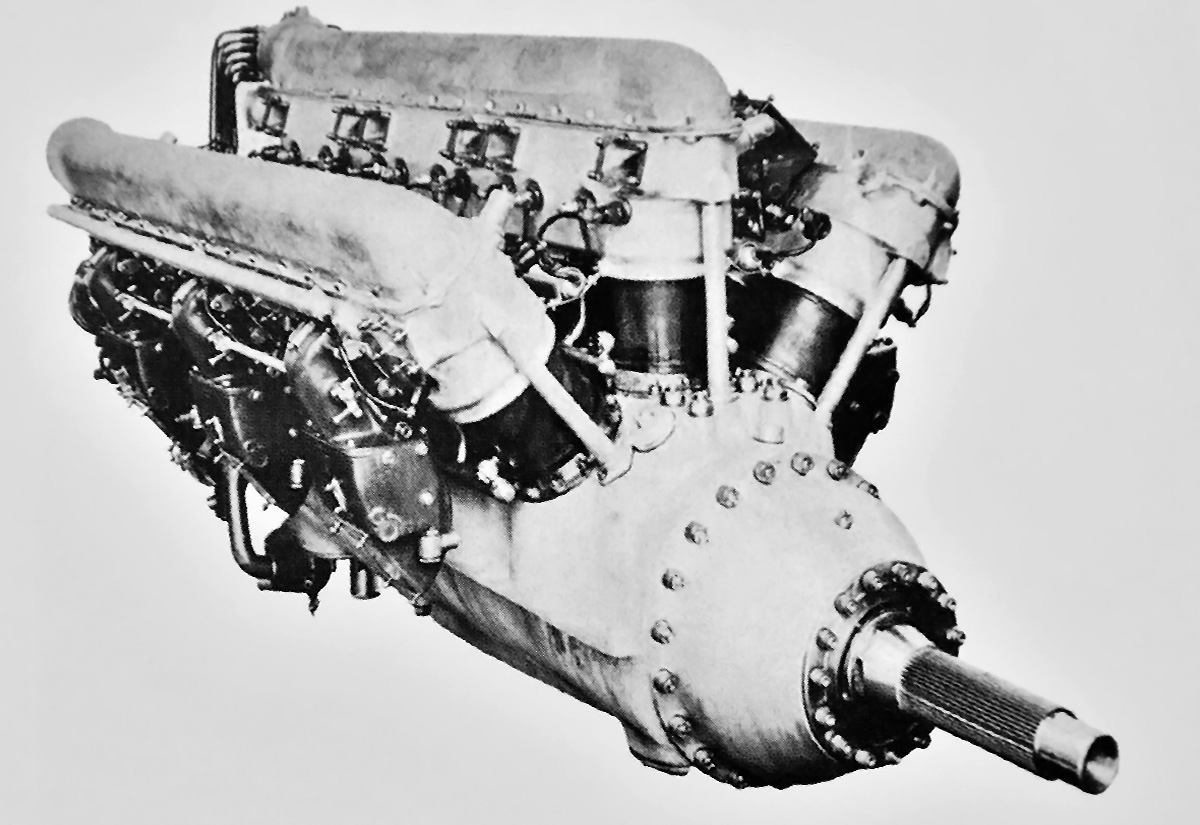
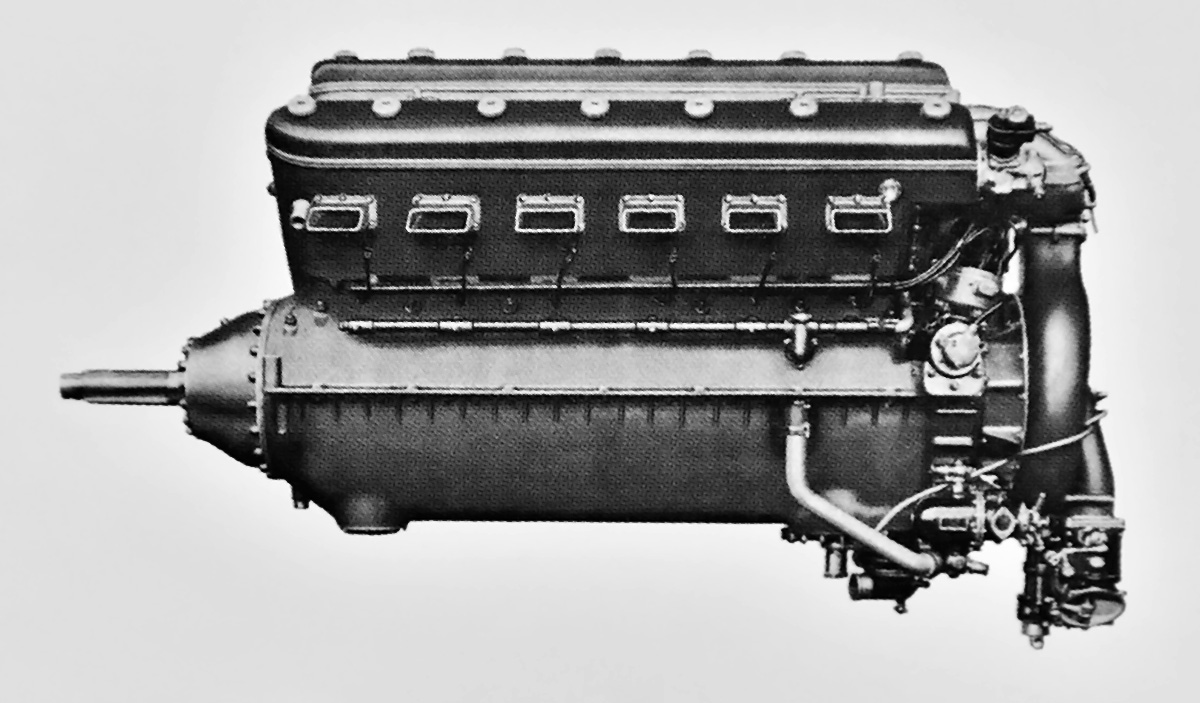
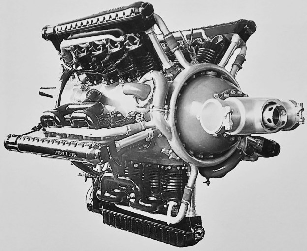
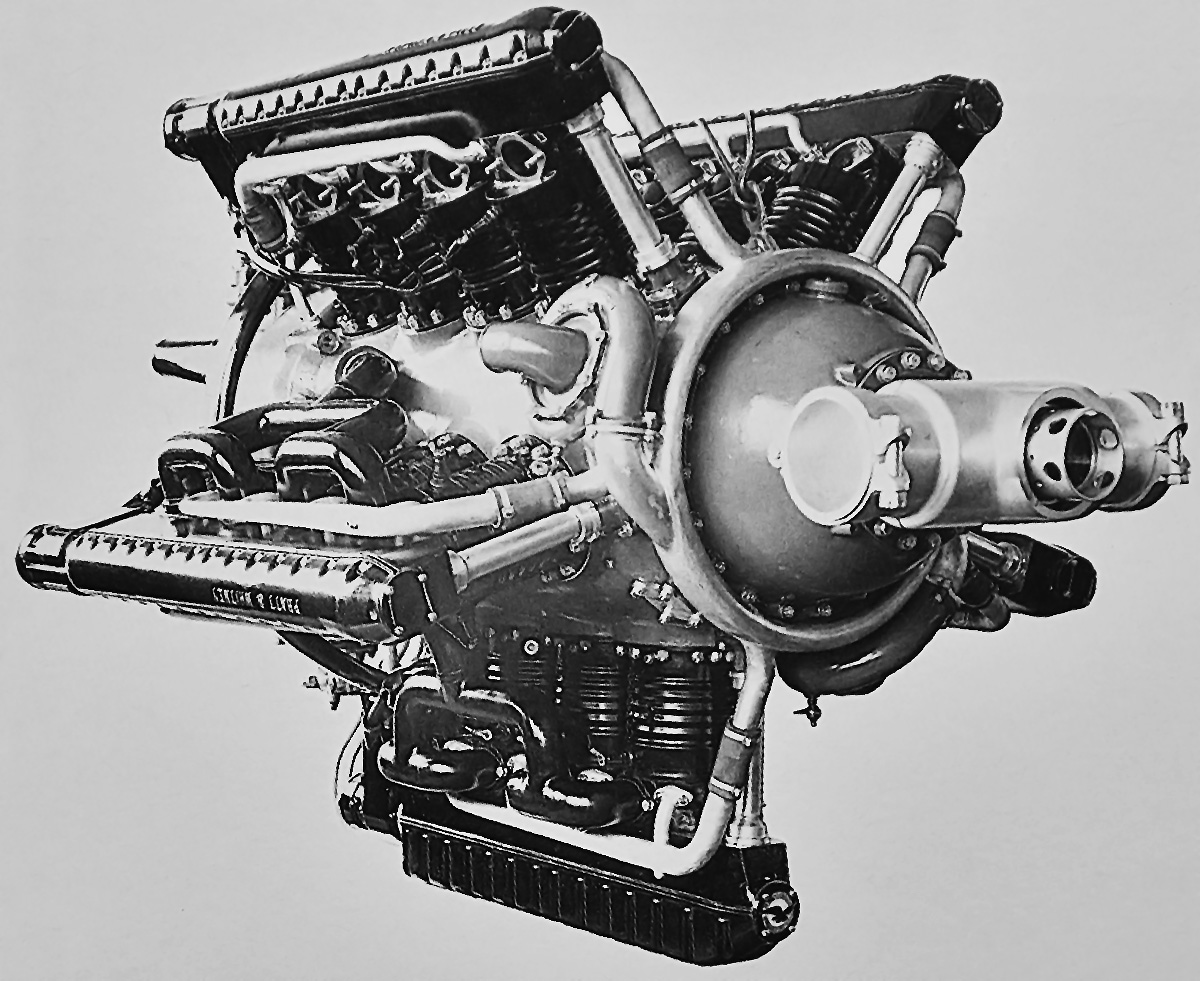
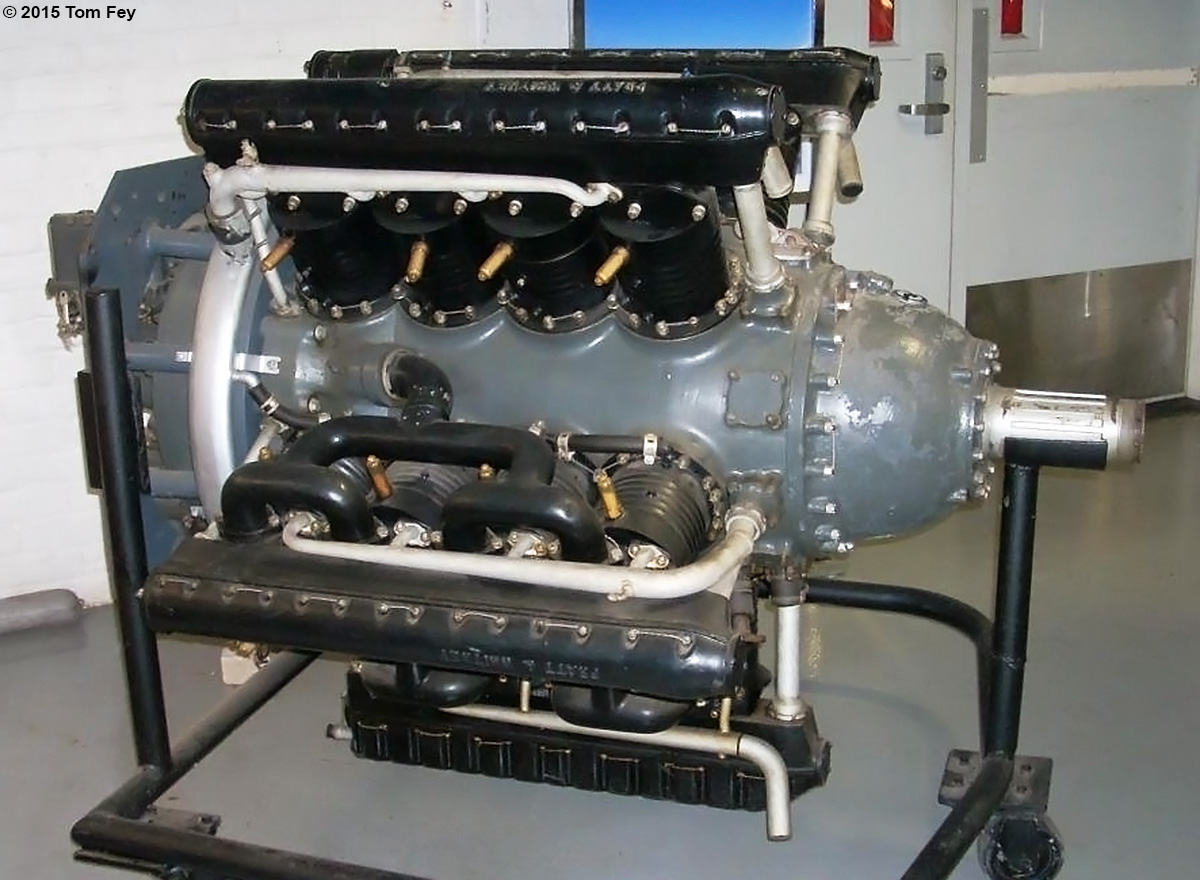
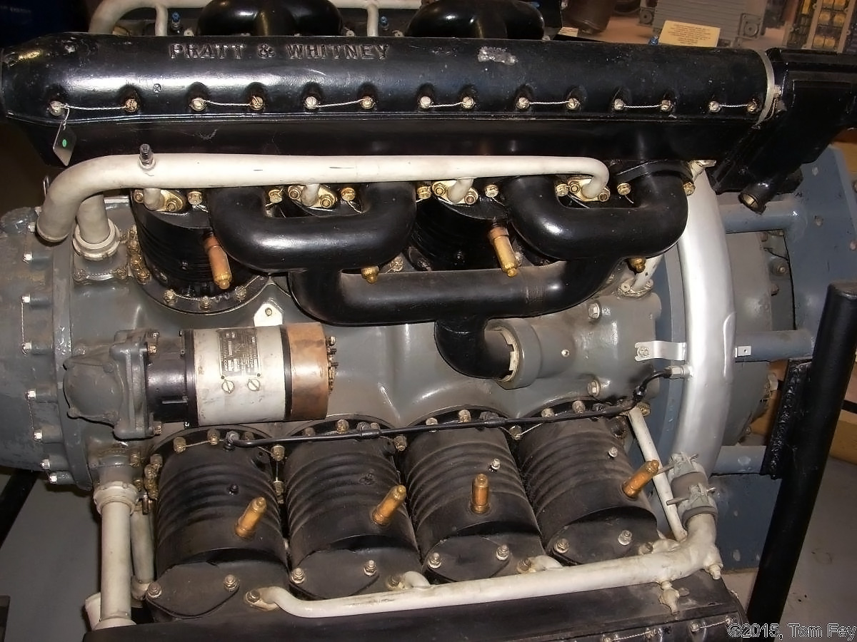
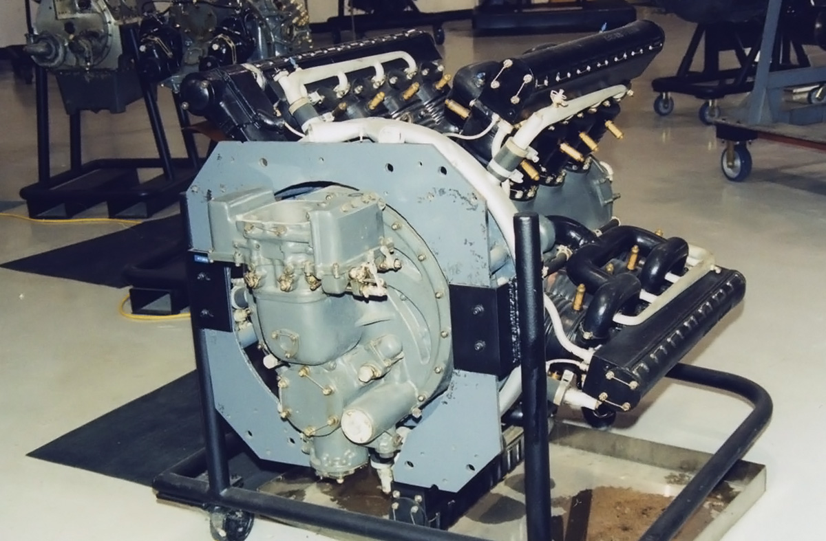
In selecting an engine for the new racer, Railton wanted something that was powerful and reliable—a high-performance engine capable of running at high-power for 24 hours. Railton selected the normally aspirated Napier Lion XIA. The Lion was a 12-cylinder aircraft engine with three banks of four cylinders. The center bank extended vertically from the crankcase, with the left and right banks angled at 60 degrees from the center bank. Normally fitted with a propeller gear reduction, the Lion XIA for the Napier-Railton was modified by Napier with a special, elongated crankshaft and the removal of the gear reduction. As tested by Napier, the special Lion XIA produced 502 hp (374 kW) at 2,200 rpm, 564 hp (421 kW) at 2,350 rpm, and 590 hp (440 kW) at 2,700 rpm. The engine was fitted at the front of the car and mounted between the chassis’ two large frame rails, which were 10 in (254 mm) tall. Five cross members secured the car’s frame.

Napier-Railton-Chassis

The chassis of the Napier-Railton with its Napier Lion engine and three-speed transmission. The two levers by the transmission were for the gear shift and driveshaft brake. The oil tank can be seen extending below the driveshaft and under what would become the cockpit.

Behind the engine was a single-plate clutch and the three-speed transmission. Since the car was to operate almost entirely at high speed, the first and second gears were much weaker than the robust third gear. This enabled the transmission to be smaller and lighter. The transmission drove the rear axle’s very strong differential, which had a 1.66 drive ratio. The forged rear axle housing was made of three sections: a center section that carried the differential, and left and right sections that carried the full-floating axle shafts. An oil sump, finned for cooling, was attached to the bottom of the axle’s center section. The car’s front and rear axles were positioned above the underslung frame rails, which enabled the car to have a low center of gravity. The suspension for the front axle used half-elliptical leaf springs, and the suspension for the rear axle used two sets of cantilever leaf springs on both sides of the car. The Napier-Railton was fitted with drum brakes on the rear axle and no brakes on the front axle. A driveshaft brake was operated by a hand lever and acted as a parking brake.

The chassis was covered by an aluminum body made by Gurney Nutting Ltd. The radiator at the front of the car was encased by the body, with a large opening for cooling air. At various times, the radiator opening was covered with vertical bars, a single bar, or no bars at all. The engine cowling had large humps for the left and right cylinder banks, a louvered top, and was secured by leather straps. Exhaust gases from each of the three cylinder banks were collected into separate manifolds, with the manifold for the center bank located on the left side of the car. An exhaust system consisting of a muffler and tailpipe extending to the rear of the car could be attached to each manifold. This system was used when the car competed at the Brooklands track. An undershield covered the bottom of the chassis.

Napier-Railton-Brooklands-grille

At 6 ft 3 in and around 240 lb, Cobb was one of the few that could make the large Napier-Railton look almost normal-size by comparison. The leather straps that secured the engine cowling passed through the humps covering the left and right cylinder banks.

The cockpit was behind the engine and offset to the right, with the driver’s feet to the right of the transmission. The throttle pedal was in the center, with the brake pedal on the right and the clutch pedal on the left. A raised scuttle panel and windscreen protected the driver. At times, an enlarged scuttle and a shield to the cockpit’s right rear were added to protect the driver from a burst tire. In addition, a covered mirror was occasionally fitted to the scuttle left of the cockpit. An 18 US gallon (15 Imp gal / 68 L) oil tank was positioned to the left of the cockpit. The tank extended under the driveshaft and below the driver’s seat, and its underside was finned for cooling. Behind the cockpit, the body of the car tapered to a short wedge. Housed behind the driver was a 78 US gallon (65 Imp gal / 295 L) fuel tank. The Napier-Railton had a 10 ft 10 in (3.30 m) wheelbase, a track of 5 ft (1.52 m), and was 15 ft 6 in (4.72 m) long. The car weighed approximately 5,000 lb (2,268 kg). Various tire sizes ranging from 19 x 7 in (483 x 178 mm) to 35 x 6 in (889 x 152 mm) were used throughout the car’s career, with smaller tires used for acceleration and larger tires fitted for top speed. The wheels were mounted to the car with knock-off hubs. For long record runs, the throttle could be held open via a cable, and lights could be added to the car. Push starting was employed to bring the Napier-Railton’s Lion engine to life.

The newly completed Napier-Railton made its debut for the press on 6 June 1933. Minor testing by Cobb and Railton occurred before the debut, and serious testing was carried out in July. The car’s public debut was at the Brooklands track on 7 August 1933. Cobb set a Brooklands standing start lap record on the first lap of the Napier-Railton’s first race, covering the 2.75-mile (4.43-km) course at an average of 120.59 mph (194.07 km/h). The Napier-Railton went on to win the short race.

Napier-Railton-completed

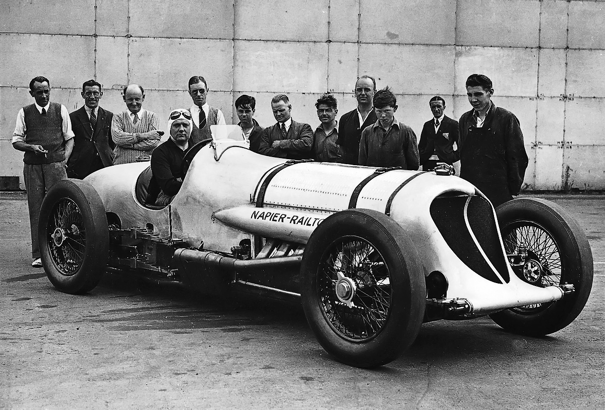
A builder and team photo of the Napier-Railton at Brooklands. Cobb is in the driver’s seat; Ken Taylor is on the far left; Ken Thomson is third from left; Reid Railton is fourth from left. Note the single vertical bar on the radiator housing.

Cobb then took the Napier-Railton to the 1.58-mile (2.55-km) speed ring at the Autodrome de Linas-Montlhéry track south of Paris, France for an attempt on the 24-hour record. Over 6 and 7 August 1933, American Ab Jenkins had established a new 24-hour record of 117.821 mph (189.615 km/h) driving a Pierce-Arrow V-12 at the Bonneville Salt Flats in Utah. This was the speed to beat. Cobb had previously arranged to use some equipment provided by George Eyston, a friend and fellow racer who was familiar with endurance runs at Montlhéry. The Napier-Railton’s exhaust mufflers were removed, and individual stacks were used. An angled shield was added to the scuttle left of the cockpit to block the exhaust flame glare from the center bank during night running. For the 24-hour attempt, Cobb’s co-drivers were Brian Lewis, Cyril Paul, and Tim Rose-Richards. Starting the record run on 2 October 1933, the car tore through its tires, and some difficulty was experienced with changing them. Push-starting the car after pit stops was also problematic. Rules stipulated that the car needed to travel forward under its own power. After shutting the car off during a pit stop, the crew needed to push it back some distance so that it could be pushed forward and started before it reached its original stopping point. Although several records were set with the Napier-Railton, including 200 miles (322 km) at 126.84 mph (204.13 km/h), 500 miles (805 km) at 123.27 mph (198.38 km/h), and six hours at 122.62 mph (197.34 km/h), the 24-hour attempt was abandoned after the radiator developed a leak and parts of the Montlhéry circuit began to break up under the car’s relentless pounding.

Back at Brooklands, Cobb and the repaired Napier-Railton set a new standing-start mile (1.6 km) record at an average of 102.52 mph (164.99 km/h) on 31 October 1933. On 4 November, the standing-start kilometer (.6 mi) record fell at 88.521 mph (142.461 km/h). Cobb was also timed covering 1 km (.6 mi) at 143.67 mph (231.21 km/h), the fastest speed recorded at Brooklands up to that point. On 2 April 1934, the Napier-Railton established a new Brooklands Outer Circuit lap record of 139.71 mph (224.84 km/h). Later that month, the Napier-Railton was back at Montlhéry for another 24-hour attempt. Cobb was supported by co-drivers Charles Brackenbury, Freddie Dixon, and Cyril Paul. Starting on 16 April, six hours passed at an average of 123.01 mph (197.97 km/h), 12 hours at 121.19 mph (195.04 km/h), and 2,000 miles (3,219 km) at 120.71 mph (194.26 km/h). On 17 April, after 19.5 hours had elapsed, Dixon lost control of the car, hit a guardrail and wound up in an infield ditch. Dixon was unharmed, but the Napier-Railton was damaged, and the record run was over. An AMR 33 light Army tank was required to pull the heavy car from the ditch. The Napier-Railton racer returned to the Thomson & Taylor works where it was repaired. At Brooklands on 6 August 1934, Cobb won the Championship Race and set a new Outer Circuit lap record at 140.93 mph (226.77 km/h).

Napier-Railton-Brooklands-jump

Cobb takes flight as the Napier-Railton transitions over the River Wey to the Railway Straight and Brooklands. The bridge over the river created a bump that caused faster cars to become airborne, an indication of how Brooklands was a rough track. The image illustrates both the enlarged scuttle and the rear shield added to protect the driver. Note the bar-less radiator housing.

In mid-August 1934, Jenkins increased the 24-hour record to 127.229 mph (204.756 km/h). Cobb still wanted to set his own 24-hour record, and Jenkins’ success on the 10-mile (16-km) circular track in the wide expanses of the Salt Flats convinced Cobb to make the trip to Bonneville in mid-1935. For the Bonneville record attempt, a 120 US gallon (100 Imp gal / 455 L) fuel tank with two filler necks replaced the 78 US gallon (65 Imp gal / 295 L) tank, and the side panels covering the engine were removed for additional cooling. Like at Montlhéry, individual exhaust stacks were used.

Cobb, his team, and the Napier-Railton arrived at Bonneville in early July 1935. Ever the sportsman, Jenkins had a lot of equipment already setup on the Salt Flats and left it there for Cobb to use. On 12 July 1935, Cobb established a new 1-hour record at 152.70 mph (245.75 km/h) and a 100-mile (161 km) record at 152.95 mph (246.15 km) while testing the car on the salt. Backed by co-drivers Charlie Dodson and Rose-Richards, Cobb and the Napier-Railton set 16 records over 15 and 16 July 1935. The average speed for 500 miles (805 km) was 147.66 mph (237.64 km/h); 1,000 miles (1,609 km) was 144.93 mph (233.24 km/h); 12 hours was 139.84 mph (255.05 km/h); 2,000 miles (3,219 km) was 137.86 mph (221.86 km/h); 3,000 miles (4,828 km) was 134.56 mph (216.55 km/h); and 24 hours was 134.85 mph (217.02 km/h). In that 24-hour period, the Napier-Railton covered 3,236 miles (5,208 km).

Napier-Railton-Bonneville-config

The Napier-Railton in front of Gus F. Koehler’s Hudson dealership in Salt Lake City in 1935. The Hudson Motor Car Company provided courtesy vehicles to Cobb and his team. In its Bonneville configuration the Napier-Railton had a larger fuel tank, individual exhaust stacks, and its engine side covers removed. American and British flags were painted atop the radiator housing. The anti-glare shield appears in place on the left side of the car, but the windscreen is missing.

While Cobb achieved his goal, the record did not stand for long. At the end of August 1935, Jenkins increased the 24-hour record to 135.580 mph (218.195 km/h), covering 3,354 miles (5,398 km) in his new Duesenberg Special. In mid-September, the record was broken again at Bonneville, this time by George Eyston in Speed of the Wind, averaging 140.52 mph (226.15 km/h) and covering 3,372 miles (5,427 km). In three months, three groups of racers in three separate cars established three new 24-hour records, which varied by less than six mph.

After returning to England, Cobb and Rose-Richards won a 500-mile (805-km) race at Brooklands on 22 September 1935. The Napier-Railton averaged 121.28 mph (195.18 km/h), a speed that would not be bettered in a 500-mile (805-km) race until the 1949 running of the Indianapolis 500. On 7 October 1935, Cobb and the Napier-Railton set a final lap record at Brooklands of 143.44 mph (216.36 km/h). This speed was not exceeded before the track was partially torn up during World War II. During the attempt, Cobb covered 1 km (.6 mi) at 151.97 mph (244.57 km/h), the fastest speed recorded at Brooklands.

Napier-Railton-Bonneville-1936

Cobb starting an attempt for the 1-hour record in 1936. The electric starting motor can be seen just before the rear tire. The driver would pull the lever that pressed the roller against the tire. The electric motor would then be turned on, driving the entire car forward. With a little bit of speed, the clutch could be let out, forcing the ever-reliable Lion engine to turn over and fire.

In mid-July 1936, Eyston increased his 24-hour record with an average speed of 149.096 mph (239.947 km/h), covering 3,578 miles (5,759 km). Cobb had already planned to make another attempt on the 24-hour record. By early September 1936, Cobb was back in Bonneville with Brackenbury, Johnny Hindmarsh, and Rose-Richards as his co-drivers. The Napier-Railton had a new external electric starting motor that, when engaged, drove the right rear tire to effectively push-start the car. Also, an exhaust manifold (without mufflers) was fitted to the center bank to reduce the glare from the flames at night. On 10 September, using the 12-mile (19-km) course, Cobb set a new 1-hour record at 167.69 mph (269.87 km/h) and covered 100 miles (161 km) at 168.59 mph (271.32 km/h). On 12 and 13 September, the Napier-Railton established four new records, including averaging 156.85 mph (252.43 km/h) over 1,000 miles (1,609 km), 149.27 mph (240.23 km/h) over 2,000 miles (3,219 km), and 150.16 mph (241.66 km/h) over 24 hours, covering 3,604 miles (5,800 km). Cobb’s new 24-hour record was less than one mph faster than the previous record set by Eyston; once again, the record did not stand for long. In late September 1936, Jenkins took back many of the records and averaged 153.823 mph (247.554 km/h) for 24 hours, covering 3,692 miles (5,942 km).

The Napier-Railton raced only at Brooklands in 1937. On 29 March, it won a race averaging 136.03 mph (218.92 km/h), the fastest race ever run at Brooklands. On 18 September 1937, Cobb, co-driver Oliver Bertram, and the Napier-Railton won a 500 km (311 mi) race averaging 127.05 mph (204.47 km/h). This was the last time the car was run on the track. Cobb retired from circle-track racing to focus attention on his Land Speed Record (LSR) car, the twin-Lion powered Railton. Eyston and Jenkins continued their duel for endurance records, and Eyston tried for absolute LSR records with his Thunderbolt car. The Napier-Railton was stored through World War II and acted as an LSR car for the 1951 film Pandora and the Flying Dutchman. Installed for the film were a streamlined radiator housing, a headrest behind the cockpit, and an elongated tail.

Napier-Railton-parachute-test

The Napier-Railton being utilized by the GQ Parachute Company to test aircraft braking parachutes. The pylon atop the rear of the car could automatically retract the parachute and store it for reuse. The streamlined nose was made for the 1951 film Pandora and the Flying Dutchman and was removed in the mid-1950s.

After Cobb’s death while attempting a water speed record in September 1952, the Napier-Railton was used by Geoffrey Quilter of the GQ Parachute Company. The car remained mostly as it had appeared in the movie, but a smaller fuel tank was fitted, and a parachute testing structure was mounted above the rear axle. To improve stopping, discs replaced the drum brakes on the car’s rear axle. Quilter used the car for a number of years to test aircraft braking parachutes. Eventually, the original radiator housing replaced the movie nose.

The Napier-Railton was purchased by Patrick Lindsay in 1961. Lindsay competed in various Vintage Sports Car Club meets and other events, and was clocked at 165 mph (266 km/h) in the Napier-Railton. After Lindsay passed, the Napier-Railton was acquired by Bob Roberts in 1971. The car was restored to a configuration similar to how it appeared while being raced at Brooklands by Cobb. After Robert’s death, the car was purchased by Victor Gauntlett in 1987 and was subsequently acquired at auction by a German collector in July 1991. Following a protracted three-year negotiation, the Napier-Railton returned to England under the ownership of Lukas Hüni in early 1997. Under an agreement with the Brookland Society, Hüni held the car until funds could be raised to purchase the Napier-Railton for the Brooklands Museum. The car’s purchase was finalized in December 1997, and the Napier-Railton was officially handed over to the Brooklands Museum on 6 May 1998. The Napier-Railton, still equipped with its original engine, is on display at the Brookland Museum and is occasionally run for special events. Over its career, the Napier-Railton set seven records at Brooklands, 11 records at Montlhéry, and 29 records at Bonneville.

Napier-Railton-current

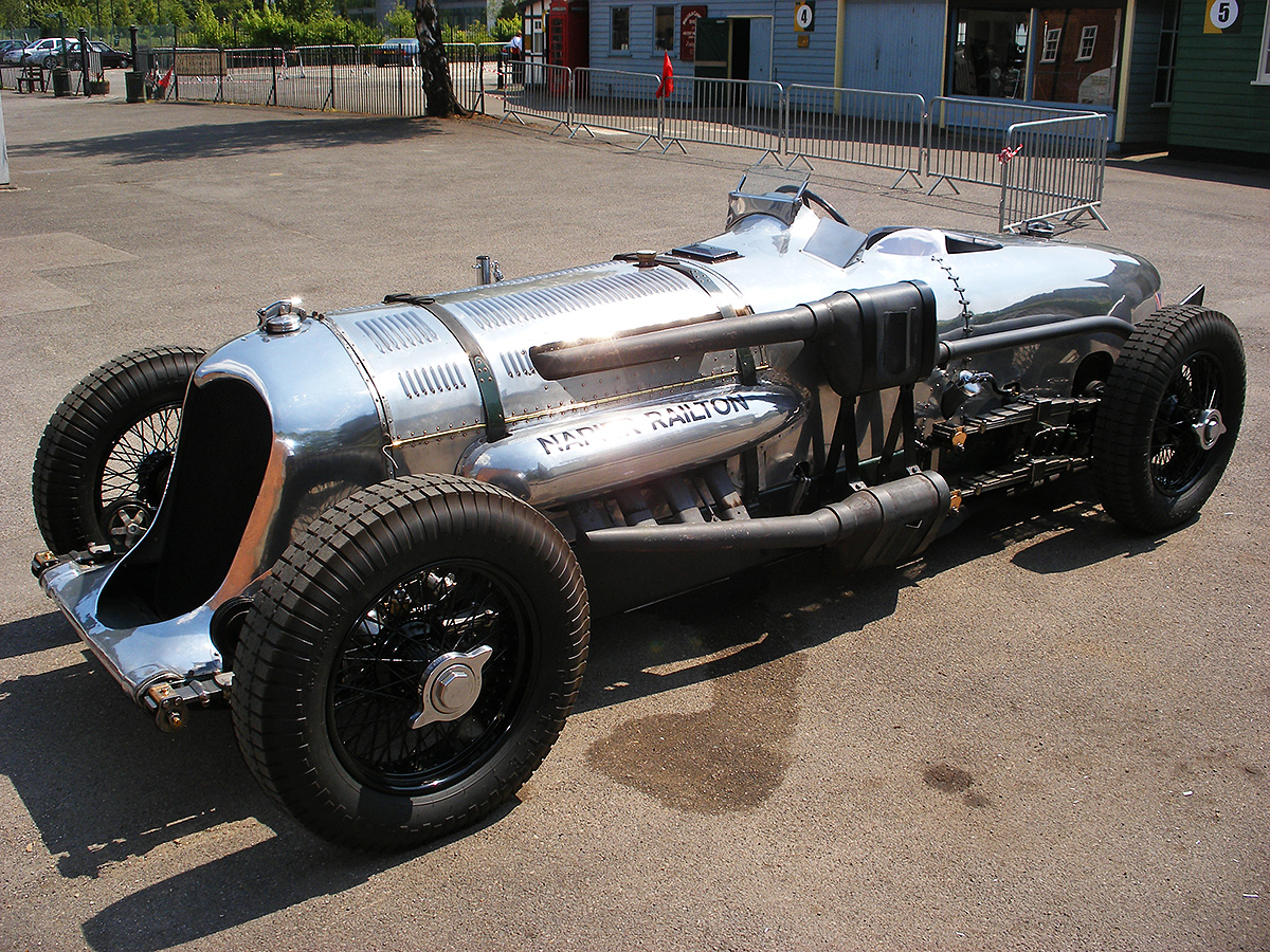
The Napier-Railton in its current form enjoying some sun. The car has been mostly returned to how it appeared for its various runs at Brooklands and is occasionally run at special events. (Dave Rogers image via Wikimedia Commons)

Sources:
Reid Railton: Man of Speed by Karl Ludvigsen (2018)
Brooklands Giants by Bill Boddy (2006)
The 1933 24-litre Napier-Railton, Profile Publications Number 28 by William Boddy (1966)
Napier: The First to Wear the Green by David Venables (1998)
The Fast Set by Charles Jennings (2004)
The John Cobb Story by S. C. H. Davis (1953)
Napier: Lions at Large 1916 – 2016 by Alan F. Vessey (2016)
– “King of Brooklands: The ex-John Cobb Napier-Railton Impressions” by Don Vorderman, Automobile Quarterly Volume IX, Number 1 (Fall 1976)

Curtiss-XF14C-2-front-left

Curtiss XF14C Carrier-Based Fighter

By William Pearce

On 30 June 1941, the United States Navy, in preparation for the future of aerial combat, ordered prototypes of the Grumman F6F Hellcat carrier fighter and the F7F Tigercat heavy fighter. The Hellcat was intended to replace the F4F Wildcat and counter the Japanese Mitsubishi A6M Zero. The Tigercat was intended to out-perform and out-gun all other fighters. The Hellcat and Tigercat went on to serve with distinction for many years. Also on 30 June 1941, the Navy ordered two prototypes of the Curtiss XF14C.

Curtiss-XF14C-2-front-left

The Curtiss XF14C-2 with its contra-rotating propellers and four 20 mm cannons appears as an imposing aircraft. However, its performance did not meet expectations. Note the stagger of the cannons and the glazed, rearward-sliding canopy.

Since 1939, the Navy had been supporting the development of the 2,300 hp (1,715 kW) Lycoming XH-2470 engine. The XH-2470 was a liquid-cooled, 24-cylinder engine in a vertical H configuration. The Navy’s support for the XH-2470 was unusual, as it had a long history of exclusively using air-cooled radial engines. In addition, the Navy had no applications for the engine until the XF14C was proposed as a high-performance fighter.

The Curtiss-Wright XF14C was designed at the company’s main facility in Buffalo, New York. The two XF14C-1 prototypes ordered were assigned Navy Bureau of Aeronautics numbers (BuNo) 03183 and 03184. Most sources state that the XF14C-1 was to be powered by the XH-2470-4 engine. Lycoming documents indicate that the -4 featured contra-rotating propellers. However, some sources state the XF14C-1 had a single rotation propeller that was 14 ft 2 in (4.32 m) in diameter. The XH-2470-2 used a single rotation propeller, but no sources have been found specifically stating that this was the engine for XF14C-1.

Regardless of the exact engine model and propellers, the XF14C-1 was an all-metal, low-wing aircraft with standard landing gear and a conventional layout. The gear was fully retractable, including the tail-wheel, and the main legs had a wide track. The arrestor tail hook extended from the extreme rear of the fuselage. The outer panels of the wings had around 7.5 degrees of dihedral and folded up for aircraft storage on an aircraft carrier. The fixed wing section had a flap along its trailing edge, and the folding section had a small flap on its inner trailing edge. The rest of the folding section had an aileron along its trailing edge. Just inboard of the wing-fold was the aircraft’s armament. Initially, each wing would house three .50-cal machine guns, but this was revised to two 20 mm cannons with 166 rounds per gun.

Curtiss-XF14C-2-right-side

Side profile of the XF14C-2 illustrates the large exhaust pipe from the turbosupercharger under the aircraft. The inscription under the diving figure on the cowling reads “Coral Princess.” Note the large wheel covers and the retracted tail hook.

The XF14C-1 had a 46 ft (14.02 m) wingspan, was 38 ft 4 in (11.68 m) long, and was 14 ft 6 in (4.42 m) tall. With the wings folded, the aircraft’s span was 22 ft 6 in (6.89 m). The XF14C-1 had an estimated speed of 344 mph (554 km/h) at 3,500 ft (1,067 m) and 374 mph (602 km/h) at 17,000 ft (5,182 m). Its initial rate of climb was 2,810 fpm (14.3 m/s), and it had a service ceiling of 30,500 ft (9,296 m). The aircraft had an empty weight of 9,868 lb (4,476 kg), a gross weight of 12,691 lb (5,757 kg), and a maximum weight of 13,868 lb (6,290 kg). The XF14C-1 had a range of 1,080 miles (1,738 km) at 176 mph (283 km/h) on 230 US gallons (192 Imp gal / 871 L) of internal fuel. With two 75-US gallon (62 Imp gal / 284 L) drop tanks, range increased to 1,520 miles (2,446 km) at 164 mph (264 km).

Wind tunnel tests conducted by the Navy in October 1942 indicated that the Curtiss-provided performance specifications for the XF14C-1 were optimistic, but the program moved forward. The first airframe (BuNo 03183) was mostly complete by September 1943. However, delays with the XH-2470 left the XF14C-1 without an engine. The engine delay gives some credence to a contra-rotating version of the XH-2470 being used in the XF14C-1. A single rotation XH-2470 had passed a Navy acceptance test in April 1941, and a single rotation XH-2470 that was delivered to the Army Air Force had made its first flight in the Vultee XP-54 on 15 January 1943. With the availability of the single-rotation XH-2470 for the Army Air Force, it seems that such an engine could have been supplied to Curtiss for the XF14C-1 if that is what the aircraft needed. The Navy subsequently dropped its participation in the XH-2470 engine program, and the XF14C-1 was cancelled in December 1943.

Curtiss and the Navy negotiated to proceed with the XF14C program by changing the engine to the experimental Wright XR-3350-16. The -16 was turbosupercharged and used contra-rotating propellers. Rated at 2,250 hp (1,678 kW) at 32,000 ft (9,754 m), the 18-cylinder, air-cooled, radial engine offered a higher service ceiling than the XH-2470. This interested the Navy, as they were looking toward developing a high-altitude interceptor. With the new engine, the Curtiss aircraft became the XF14C-2 and was pushed into a high-altitude fighter role. The cancellation of the XF14C-1 terminated all work on the second prototype, BuNo 03184, which was never built.

Curtiss-XF14C-2-wings-folded

The XF14C-2’s outer wing section folded up just outside of the cannons. Note the gap around the spinner for cooling the two-row, 18-cylinder R-3350 engine and that the second set of propeller blades have cuffs to aid cooling.

BuNo 03183 became the XF14C-2 and was modified to accept the new engine. A six-blade, contra-rotating Curtiss Electric propeller with a diameter of approximately 12 ft 10 in (3.91 m) was installed on the XR-3350-16 engine. The cowling incorporated an intake scoop under the engine. Oil coolers were placed in extensions of the XF14C-2 wing roots. The turbosupercharger was installed directly behind the engine in a housing that extended back from the lower cowling. A large exhaust pipe from the turbosupercharger extended below the aircraft behind the main wheels.

The Curtiss XF14C-2 had the same 46 ft (14.02 m) wingspan as the XF14C-1 but was shorter at 37 ft 9 in (37.75 m) long and 12 ft 4 in (3.76 m) tall. The aircraft had an estimated speed of 317 mph (510 km/h) at sea level and 424 mph (682 km/h) at 32,000 ft (9,754 m). The XF14C-2’s initial rate of climb was 2,700 fpm (13.7 m/s), and it had a service ceiling of 39,500 ft (12,040 m). The aircraft had an empty weight of 10,582 lb (4,800 kg), a gross weight of 13,405 lb (6,080 kg), and a maximum weight of 14,950 lb (6,781 kg). At a cruising speed of 172 mph (277 km/h), the XF14C-2 had a range of 950 miles (1,529 km) on 230 US gallons (192 Imp gal / 871 L) of internal fuel and 1,355 miles (2,181 km) with two 75-US gallon (62 Imp gal / 284 L) drop tanks.

The XF14C-2 was first flown in July 1944 and delivered to the Navy on 2 September 1944. Testing quickly revealed that the aircraft did not meet the expected performance and offered no advantage over fighters already in service. Top speeds of only 300 mph (483 km/h) at sea level and 398 mph (641 km/h) at 32,000 ft (9,754 m) were achieved. The aircraft’s engine and propeller combination also caused a bad vibration throughout the airframe. With the XF14C-2 underperforming, no urgent need for a high-altitude fighter, and all the R-3350 production dedicated for the Boeing B-29 Superfortress and Convair B-32 Dominator bombers, the Navy cancelled the XF14C-2. The airframe was eventually scrapped. The XF14C-2 was the last piston-engine fighter built by Curtiss.

Curtiss proposed the XF14C-3 to truly fulfill the role of a high-altitude fighter. It had a pressurized cockpit and could operate at 40,000 ft. Studies of the XF14C-3 were conducted at Navy expense until early 1945, but no aircraft was built.

Curtiss-XF14C-2-front-right

The XF14C-2 had oil-coolers in the wing roots. Note the dihedral angle of the outer wing sections. The engine and propeller combination caused an unacceptable level of vibration.

Sources:
Curtiss Fighter Aircraft by Francis H. Dean and Dan Hegedorn (2007)
US Experimental & Prototype Aircraft Projects: Fighters 1939-1945 by Bill Norton (2008)
American Secret Projects 1 by Tony Buttler and Alan Griffith (2015)
To Join with the Eagles by Murry Rubenstein and Richard M. Goldman (1974)
The American Fighter by Enzo Angelucci and Peter Bowers (1987)

Latecoere 631-03

Latécoère 631 Flying Boat Airliner

By William Pearce

On 12 March 1936, the civil aeronautics department of the French Air Ministry requested proposals for a commercial seaplane with a maximum weight of 88,185 lb (40,000 kg) and capable of carrying at least 20 passengers (with sleeping berths) and 1,100 lb (500 kg) of cargo 3,730 miles (6,000 km) against a 37 mph (60 km/h) headwind. In addition, the aircraft needed a normal cruising speed of 155 mph (250 km/h). This large passenger aircraft was to be used on transatlantic service to both North and South America. Marcel Moine, head engineer at Latécoère (Société Industrielle Latécoère, SILAT) had already been working on an aircraft to meet similar goals. In late 1935, Moine had designed an aircraft for service across the North Atlantic with a maximum weight of 142,200 lb (64,500 kg). However, the design was seen as too ambitious. Moine modified the design to meet the request issued in 1936, and the aircraft was proposed to the Air Ministry as the Latécoère 630.

Latecoere 631-04

The Latécoère 631 was one of the most impressive flying boats ever built. Unfortunately, its time had already passed before the aircraft could enter service. Laté 631-04 (fourth aircraft) F-BDRA is seen here, and it was the second of the type in service for Air France. Note the configuration of the flaps and ailerons.

The Laté 630 was an all-metal, six-engine flying boat with retractable floats. The 930 hp (694 kW), liquid-cooled Hispano Suiza 12 Ydrs was selected to power the 98,860 lb (44,842 kg) aircraft, which had a 187 ft (57.0 m) wingspan, was 117 ft 9 in (35.9 m) long, and had a range of 4,909 miles (7,900 km). On 15 November 1936, order 575/6 was issued for detailed design work of the Laté 630 and a model for wind tunnel tests. This was followed by order number 637/7 for a single Laté 630 prototype on 15 April 1937. However, the Air Ministry cancelled the Laté 630 on 22 July 1937, stating that advancements in aeronautics enabled the design and construction of a larger and more capable aircraft. Construction of the Potez-CAMS 161, which was designed under the same specifications as the Laté 630, was allowed to continue.

Taking aeronautical advancements into consideration, the Air Ministry issued an updated request for an aircraft with a maximum weight of 154,323 lb (70,000 kg) and capable of transporting 40 passengers and 11,000 lb (5,000 kg) of cargo with a normal cruising speed of over 186 mph (300 km/h). To meet the new requirements, Moine and Latécoère enlarged and repowered the Laté 630 design, creating the Laté 631. In October 1937, detailed design work and a wind tunnel model of the Laté 631 were ordered. Order number 597/8 for a single prototype was issued on 1 July 1938. A Lioré et Olivier H-49 (which became the SNCASE SE.200) prototype was also ordered under the same specification as the Laté 631.

The Latécoère 631 was an all-metal flying boat with a two-step hull. The monocoque fuselage consisted of an aluminum frame covered with aluminum sheeting. The interior of the hull was divided into numerous passenger compartments and included a lounge/bar under the radio/navigation room (may have been in the nose in some configurations) and a kitchen at the rear. The cockpit and radio/navigation room were located above the main passenger compartment and just ahead of the wings. The cockpit was positioned rather far back from the nose of the aircraft. Numerous access doors were provided, including in the nose, side of the cockpit, and in the sides of the fuselage.

Latecoere 631 cockpit

The cockpit of the Laté 631 was rather spacious. Note the six throttle levers suspended above the pilot’s seat. The copilot could not reach the levers, but the flight engineer had another set of throttles. The central pylon contained the trim wheels and controls for the floats and flaps. At left in the foreground is the navigation station, and the radio station is at right.

The high-mounted wing was blended to the top of the fuselage and carried the aircraft’s six engines in separate nacelles. The wing had two main spars and a false spar. Each wing consisted of an inner section with the engine nacelles and an outer section beyond the nacelles. The outer engine nacelle on each wing incorporated a retractable float that extended behind the wing’s trailing edge. Due to interference, the float needed to be at least partially deployed before the flaps could be lowered. A passageway in the wing’s leading edge was accessible from the radio/navigation room and allowed access to the engine nacelles. Each nacelle had two downward-opening doors just behind the engine that served as maintenance platforms. A section of the firewall was removable, allowing access to the back of the engine from within the nacelle. Between the inboard engine and the fuselage was a compartment in the wing’s leading edge designed to hold mail cargo.

Originally, 1,500 hp (1,119 kW) Gnôme Rhône 18P radial engines were selected to power the Laté 631. However, the availability of these engines was in question, and a switch to 1,600 hp (1,193 kW) Wright R-2600 radial engines was made. The Gnôme Rhône 14R and the Pratt & Whitney R-2800 were also considered, but the 14R was also unavailable, and the export of R-2800 engines was restricted. Each engine turned a three-blade, variable-pitch propeller that was 14 ft 1 in (4.3 m) in diameter and built by Ratier. Later, larger propellers were used, but sources disagree on their diameter—either 14 ft 5 in or 15 ft 1 in (4.4 m or 4.6 m). It is possible that both larger diameters were tried at various times.

At the rear of the aircraft were twin tails mounted to a horizontal stabilizer that had 16.7 degrees of dihedral. All control surfaces had an aluminum frame with a leading edge covered by aluminum. The rest of the control surface was fabric covered. Movement of the control surfaces was boosted by a servo-controlled electrohydraulic system, which could be disengaged by the pilot. The slotted aileron on each wing was split in the middle and consisted of an outer and an inner section. The ailerons also had Flettner servo tabs that were used to trim the aircraft and could be engaged to boost roll control.

Latecoere 631-01 German 63-11

Laté 631-01 (F-BAHG) in German markings as 63+11. The openings for the large passenger windows existed in the airframe but were covered on Laté 631-01. The prototype aircraft was destroyed during an allied attack while in German hands on Lake Constance in April 1944.

Six wing tanks carried 7,582 gallons (28,700 L) of fuel, and each tank fed one engine. During flight, these tanks were replenished by pumping fuel from six tanks in the hull that carried 5,785 gallons (21,900 L) of fuel. The Laté 631’s total fuel capacity was 13,367 gallons (50,600 L). Each engine had its own 111-gallon (422-L) oil tank.

The Latécoère 631 had a 188 ft 5 in (57.43 m) wingspan, was 142 ft 7 in (43.46 m) long, and was 33 ft 11 in (10.35 m) tall. The aircraft had a maximum speed of 245 mph (395 km/h) at 5,906 ft (1,800 m) and 224 mph (360 km/h) at sea level. Its cruising speed was 183 mph (295 km/h) at 1,640 ft (500 m). The Laté 631 had an empty weight of 89,265 lb (40,490 kg) and a maximum weight of 163,347 lb (75,000 kg). The aircraft had a 3,766-mile (6,060-km) range with an airspeed of 180 mph (290 km/h) against a 37 mph (60 km) headwind.

Construction of the Laté 631 was started soon after the contract was issued. However, work was halted on 12 September 1939 so that Latécoère could focus on production of desperately needed military aircraft after war was declared on Germany. After the French surrender, work on the Laté 631 resumed in July 1940 but was halted again on 10 November by German order. The French and Germans negotiated over continuing work on the aircraft, which was purely for civil transportation. The Germans allowed construction to continue, and a second prototype was ordered under the same contract as the first (597/8) on 19 March 1941. The 35 Wright R-2600 engines that had been ordered were stranded in Casablanca, Morocco by the outbreak of the war in 1939. Amazingly, the hold on these engines was released, and they were delivered at the end of 1941.

Latecoere 631-02 stripes

Laté 631-02 (F-BANT) was finished at the end of the war and painted with invasion stripes for (hopefully) easy identification. The aircraft is at Biscarrosse undergoing tests, probably around the time of its first flight on 6 March 1945. Like on the prototype, the passenger windows are covered, but the windows were later added. Note the retractable float and that engine No. 5 is running.

The Laté 631-01, the first prototype, was registered as F-BAHG and completed at Toulouse, France in the summer of 1942. The aircraft was then disassembled and transported, with some difficulty, 310 miles (500 km) to Marignane in southern France. The aircraft was then reassembled for subsequent tests on Étang de Berre. The SNCASE SE.200, the Laté 631’s competitor, was built at Marignane and was nearing completion at the same time. The reassembly of Laté 631-01 was completed in October 1942, and the aircraft made its first flight on 4 November with Pierre Crespy as the pilot. Seven others, including Moine, were onboard as crew and observers. A second flight was made on 5 November, and flutter of the aileron and wing was encountered at 143 mph (230 km/h). The issues were traced to an improperly made part in the aileron control circuit that had subsequently failed.

Laté 631-01 was repaired, but German occupation of the French free zone on November 1942 brought a halt to further flight tests. On 23 November, order 280/42 was issued for two additional Laté 631s, bringing the total to four aircraft. The Germans lifted flight restrictions, and Laté 631-01 was flown again in December 1942. Test flights continued but were halted on several occasions by German orders. In April 1943, the tests were allowed to continue provided the aircraft was painted in German colors with German markings and a Lufthansa pilot was on board during the flights. Germany had essentially seized Laté 631-01 (and the SE.200) at this point and believed the aircraft could be used as a commercial transport once the “quick” war was concluded. The Germans were also interested in ways to add armament to the flying boat and make it a maritime patrol aircraft. Laté 631-01 was repainted and carried the German code 63+11 (for 631-01).

Laté 631-01 flight testing resumed in June 1943. On 20 January 1944, the aircraft took off on its 46th flight, and it was the first flight in which its gross weight exceeded 154,323 lb (70,000 kg). A second flight was made at 157,630 lb (71,500 kg). The tests had demonstrated that at 88,185 lb (40,000 kg), the Laté 631 could hold its course with three engines on the same side shut down. At 154,323 lb (70,000 kg), the course could be held with the outer two engines shut down on the same side. Some additional indications of flutter had been encountered but not understood.

Latecoere 631-02 Brazil

Laté 631-02 at Rio de Janeiro, Brazil in late October 1945. Note the open nacelle platforms, which were accessible through a wing passageway. A Brazilian flag is attached to the forward antenna mast.

Around 22 January 1944, Laté 631-01 was taken over by German forces and flown to Lake Constance (Bodensee) and moored offshore from Friedrichshafen, Germany. The SE.200 had already suffered the same fate on 17 January. On the night of 6 April 1944, Laté 631-01 and the SE.200 were destroyed at their moorings on Lake Constance by an Allied de Haviland Mosquito. The Laté 631 prototype had accumulated approximately 48 hours of flight time.

Construction of other Laté 631 aircraft had continued until early 1944, when German forces wanted Latécoère to focus on building the Junkers 488 bomber (which was never completed and was destroyed by the French Resistance). The disassembled second Laté 631 (631-02) was hidden in the French countryside until the end of the war. On 11 September 1944, order 51/44 was issued for five additional Laté 631 aircraft, which brought the total to nine. In December 1944, the components of Laté 631-02 were transported to Biscarrosse, where the aircraft was completed and assembled for testing on Lac de Biscarrosse et de Parentis. On 6 March 1945, Crespy took Laté 631-02 aloft for its first flight. While testing continued, the aircraft was christened Lionel de Marmier and was registered as F-BANT in April 1945. On 31 July, Laté 631-02 started a round trip of over 3,730 miles (6,000 km) to Dakar, Senegal, returning to Biscarrosse on 4 August. On 24 August, material for two additional Laté 631s was added to order 51/44, enabling the production of up to 11 aircraft.

On 28 September 1945, an issue with the autopilot in Laté 631-02 caused a violent roll to the right that damaged the wing, requiring the replacement of over 8,000 rivets to affect repairs. The aircraft was quickly fixed so that a scheduled propaganda flight to Rio de Janeiro, Brazil could be made on 10 October 1945. On that day, Laté 631-02 collided with a submerged concreate mooring block while taxiing and tore a 6 ft 7 in (2 m) gash in the hull. Upset over this incident, French authorities took the opportunity to nationalize the Latécoère factories. Production of the last six Laté 631 aircraft was spread between AECAT (which was formed from Latécoère), Breguet, SNCASO, and SNCAN. SNCASO at Saint-Nazaire would be primarily responsible for the production of aircraft No. 6, 8, and 10, and SNCAN at Le Havre would be primarily responsible for aircraft No. 7, 9, and 11. Laté 631-02 eventually made the flight to Rio de Janeiro, with 45 people on board, arriving on 25 October 1945.

Latecoere 631-03

Laté 631-03 (F-BANU) was the third aircraft completed. Its first flight was on 15 June 1946, and it crashed during a test flight on 28 March 1950 while investigating the loss (in-flight break up) of Laté 631-06 on 1 August 1948. Investigation of Laté 631-03’s crash revealed vibration issues with the engines and wings, and led to a solution to prevent further accidents.

On 31 October 1945, the first tragedy struck the Laté 631 program. While on a flight between Rio de Janeiro and Montevideo, Uruguay with 64 people on board, Laté 631-02 suffered a propeller failure on the No. 3 (left inboard) engine. The imbalance caused the No. 3 engine to rip completely away from the aircraft. A separated blade damaged the propeller on the No. 2 engine (left middle), which resulted in that engine almost being ripped from its mounts. Another separated blade flew through the fuselage, killed one passenger, and mortally wounded another (who later died in a hospital). An emergency landing was performed on Laguna de Rocha in Uruguay. The failure of the Ratier propeller was traced to its aluminum hub, which was subsequently replaced with a steel unit. The recovery of the aircraft was performed by replacing the missing engine with one from the right wing. The four-engine aircraft, with a minimal crew, was flown to Montevideo on 13 November for complete repairs, which took three months.

In February 1946, three Laté 631 aircraft were purchased by Argentina, but this deal ultimately fell through, with Argentina never paying for the aircraft. In May 1946, an agreement was reached in which Air France would take possession of three Laté 631 aircraft. On 15 June 1946, Jean Prévost made the first flight of Laté 631-03 at Biscarrosse. The aircraft was registered as F-BANU, christened as Henri Guillaumet, and soon transferred to Air France.

Laté 631-04 was registered as F-BDRA, and its first flight occurred on 22 May 1947 at Biscarrosse. The aircraft was the second Laté 631 to go to Air France. Laté 631-05 was registered as F-BDRB, and its first flight occurred on 22 May 1947. Laté 631-06, registered as F-BDRC, made its first flight on 9 November 1947, taking off from the Loire estuary near Saint-Nazaire, France. Laté 631-06 F-BDRC was the third aircraft for Air France.

Latecoere 631-05

Laté 631-05 (F-BDRB) first flew on 22 May 1947. The aircraft was slated to be converted into a cargo transport, but that never occurred. The aircraft was damaged beyond economical repair during a hangar collapse in February 1956.

Laté 631-07, registered as F-BDRD, made its first flight on 27 January 1948. The aircraft was lost on 21 February during a test flight from Le Havre to Biscarrosse. Laté 631-07 had taken off in poor weather and was not equipped for flying on instruments alone. It crashed into the English Channel (Bay of Seine) off Les-Dunes-de-Varreville (Utah Beach). A definitive cause was never found, but it was speculated that either the pilot lost spatial orientation and crashed into the sea, or that the pilot was flying very low or trying to land after the weather closed in and struck wreckage left behind from the D-Day landings at Utah Beach. Regardless, all 19 on board, which were the crew and Latécoère engineers, were killed.

On 1 August 1948, Air France Laté 631-06 F-BDRC was lost over the Atlantic flying between Fort-de-France, Martinique and Port-Etienne (now Nouadhibou), Mauritania. Wreckage was recovered that indicated an in-flight breakup that possibly involved a fire or explosion, but a definitive cause was never determined. None of the 52 people on board survived. F-BDRC had accumulated 185 flight hours at the time of the accident, and Air France subsequently withdrew its two other Laté 631s from service. Laté 631-04 F-BDRA participated in the search for survivors, flying a total of 75 hours, including a single 26-hour flight.

The flying boat era had ended during the 10 years between when the Latécoère 631 was ordered in 1938, and when the aircraft went into service with Air France in 1947. The advances in aviation during World War II had shown that landplanes were the future of commercial aviation. Following the accidents, there was no hope for the Laté 631 to be used as a commercial airliner. With four completed aircraft and another four under construction, the decision was made to convert the Laté 631 into a cargo aircraft.

Latecoere 631-06 Air France

Laté 631-06 (F-BDRC) made its first flight on 9 November 1947. It was the third (and final) aircraft to be received by Air France. On 1 August 1948, Laté 631-06 disappeared over the Atlantic with the loss of all 52 on board. Air France withdrew its remaining Laté 631 aircraft as a result. Note the access hatch atop the fuselage. Another hatch existed behind the wings.

On 28 November 1948, Laté 631-08 F-BDRE was flown for the first time, taking off from Saint-Nazaire. Laté 631-08 was originally intended as an additional aircraft for Air France but was orphaned after the crash of Laté 631-06. Laté 631-08, along with Laté 631-03, were eventually given to a new company, SEMAF (Société d’Exploitation du Matériel Aéronautique Français / French Aircraft Equipment Exploitation Company). SEMAF was founded in March 1949 and worked to develop the Laté 631 as an air freighter. Laté 631-08 F-BDRE was converted to a cargo aircraft by strengthening its airframe and installing a 9 ft 2 in x 5 ft 3 in (2.80 x 1.60 m) cargo door on the left side of the rear fuselage. The aircraft was first flown with the modifications on 8 June 1949. Laté 631-08 soon began hauling fabric and manufactured products between France and various places in Africa. The aircraft had completed 12 trips by March 1950.

Laté 631-09 F-BDRF preceded Laté 631-08 into the air. Laté 631-09’s first flight occurred on 20 November 1948 at Le Harve. Laté 631-10 F-BDRG made its first flight on 7 October 1949 from Saint-Nazaire. Both of these aircraft were flown to Biscarrosse and stored with the never completed Laté 631-11 F-BDRH. Laté 631-09 and -10 were later reregistered as F-WDRF and F-WDRG.

Laté 631-03 F-BANU was reregistered as F-WANU when it underwent tests to measure vibrations of the airframe and engines. This was done in part to discover what led to the loss of Laté 631-06 F-BDRC. On 28 March 1950, Laté 631-03 made its second flight of the day, taking off from Biscarrosse. With engine power pushed up, the left wing began to flutter, and the outer section of the left aileron broke away. Laté 631-03 began to spin, turned on its back, and continued to spin until it impacted the water inverted. The 12 people on board, which included the crew and engineers from Latécoère and Rotol, were killed instantly. Many witnessed the crash, and the wreckage of Laté 631-03 was recovered. Examination revealed that the engines with a .4375 gear reduction and operating at 1,925 rpm during cruise flight turned the propeller at 840 rpm. This resonated with a critical frequency of the wings, ailerons and Flettner tabs, which was 840 cycles per minute. The interaction rapidly fatigued parts in the outer aileron control system and caused them to fail. The damaged aileron system allowed the aileron to flutter, breaking the control system completely and leading to a complete loss of aircraft control.

Latecoere 631-08

Laté 631-08 (F-BDRE) is seen here with its updated registration of F-WDRE. Laté 631-08 was the only aircraft that operated as an air freighter.

At the time if the accident, Laté 631-03 had been reengined with R-2600 engines incorporating a .5625 gear reduction. These engines were installed on later Laté 631 aircraft and retrofitted on the earlier aircraft. However, nearly all of the Laté 631-03’s 1,001 hours were with the other engines, which was enough to have fatigued the aileron control to its breaking point. The loss of Laté 631-03 led to the collapse of SEMAF.

With the cause of the crash known, a new company was formed to upgrade the Laté 631 fleet and modify them for cargo service. La Société France Hydro (France Hydro Company) was given charge of Laté 631-02 and Laté 631-08, which was reregistered as F-WDRE. Modifications to prevent a reoccurrence of Laté 631-03’s crash were incorporated into the aircraft, and Laté 631-08 returned to cargo service in late 1951. Laté 631-08 flew a Biscarrosse-Bizerte-Bahrain-Trincomalee-Saigon route of some 7,460 miles (12,000 km) starting in March 1952. The aircraft departed Bizerte, Tunisia with a takeoff weight of 167,000 lb (75,750 kg), the highest recorded for a Laté 631. By 1953, Laté 631-08 was hauling cotton from Douala, Cameroon to Biscarrosse. This had proven somewhat lucrative, and a cargo-conversion of Laté 631-02 was started. Laté 631-05 was also transferred to France Hydro, but little was done with the aircraft. On 10 September 1955, Laté 631-08 broke apart during a violent thunderstorm while over Sambolabo, Cameroon. All 16 people on board were killed. The Latécoère 631 was withdrawn from service after this accident, and no further attempts were made to use the aircraft.

In February 1956, Laté 631-05, -10, and -11 were damaged beyond economical repair when the roof of the Biscarrosse hangar collapsed after heavy snowfall. All of the remaining Latécoère 631s were subsequently scrapped, most in late 1956. In 1961, the remains of Laté 631-01 and the SE.200 prototype were raised from Lake Constance by a Swiss recovery team and subsequently scrapped.

Latecoere 631-08 France-Hydro

Laté 631-08 while in service with France Hydro. The aircraft crashed in a storm on 10 September 1955; this was the last flight of any Laté 631. The remaining aircraft were later scrapped. Note the open door on the bow and the open hatch forward of the cockpit that led to a cargo hold.

Sources:
Les Paquebots Volants by Gérard Bousquet (2006)
Latécoère: Les avions et hydravios by Jean Cuny (1992)
https://aviation-safety.net/database/types/Latecoere-631/database
https://www.baaa-acro.com/crash-archives?field_crash_aircraft_target_id=Lat%C3%A9co%C3%A8re%20631%20(29691)

Yokosuka YE2H front

Yokosuka YE2H (W-18) and YE3B (X-24) Aircraft Engines

By William Pearce

After World War I, the Japanese Navy established the Aircraft Department of the Hiro Branch Arsenal, which was part of the Kure Naval Arsenal. These arsenals were located near Hiroshima, in the southern part of Japan. The Aircraft Department was the Japanese Navy’s first aircraft maintenance and construction facility. In April 1923, the Hiro Branch Arsenal became independent from the Kure Naval Arsenal and was renamed the Hiro Naval Arsenal (Hiro).

Kawanishi E7K1 floatplane

The Kawanishi E7K1 floatplane served into the 1940s and was powered by the Hiro Type 91 W-12 engine. The Type 91 was based on the Lorraine 12Fa Courlis.

In 1924, the Japanese Navy purchased licenses from Lorraine-Dietrich in France to manufacture the company’s 450 hp (336 kW) 12E aircraft engine. The Lorraine 12E was a liquid-cooled, W-12 aircraft engine, and Hiro was one of the factories chosen to produce the engine. Hiro manufactured three different versions of the Lorraine engine, appropriately called the Hiro-Lorraine 1, 2, and 3. In the late 1920s, Hiro started designing its own engines derived from the Lorraine architecture. Hiro also produced engines based on the updated Lorraine 12Fa Courlis W-12. It is not clear if Hiro obtained a license to produce the 12Fa or if the production was unlicensed. The most successful of the Hiro W-12 engines was the 500–600 hp (373–447 kW) Type 91, which was in service until the early 1940s. Modeled after the 12Fa Courlis, the Type 91 had a bank angle of 60-degrees and four valves per cylinder. The engine had a 5.71 in (145 mm) bore, a 6.30 in (160 mm) stroke, and displaced 1,935 cu in (31.7 L).

Like Lorraine, Hiro also produced W-18 engines. Hiro’s first W-18 engine was built in the early 1930s and used individual cylinders derived from the type used on the 12Fa Courlis / Type 91. While Hiro’s W-18 engine may have been inspired by the Lorraine 18K, the engine was not a copy of any Lorraine engine. Reportedly, Hiro’s first W-18 had a 60-degree bank angle between its cylinders. The engine did not enter production and was superseded in 1934 by the Type 94. The Type 94 replaced the earlier engine’s individual cylinders with monobloc cylinder banks and used a 40-degree angle between the banks. The W-18 engine had a 5.71 in (145 mm) bore and a 6.30 in (160 mm) stroke. The Type 94 displaced 2,902 cu in (47.6 L) and produced 900 hp (671 kW) at 2,000 rpm. The engine was 86 in (2.18 m) long, 44 in (1.11 m) wide, 43 in (1.10 m) tall, and weighed 1,631 lb (740 kg). Only a small number of Type 94 engines were produced, and its main application was the Hiro G2H long-range bomber, of which eight were built. The engine was found to be temperamental and unreliable in service.

Hiro G2H1 bomber

The Hiro G2H1 bomber was the only application for the company’s Type 94 W-18 engine. The engine was problematic, and only eight G2H1s were built. Note the exhaust manifold for the center cylinder bank.

By the mid-1930s, the Navy’s aircraft engine development had been transferred from Hiro to the Yokosuka Naval Air Arsenal (Yokosuka). For a few years, the Navy and Yokosuka let aircraft engine manufacturers develop and produce engines rather than undertaking development on its own. However, around 1940, Yokosuka began development of a new W-18 aircraft engine, the YE2.

The Yokosuka YE2 was based on the Hiro Type 94 but incorporated many changes. The liquid-cooled YE2 had an aluminum, barrel-type crankcase, and its three aluminum, monobloc cylinder banks were attached by studs. The cylinder banks had an included angle of 40 degrees and used crossflow cylinder heads with the intake and exhaust ports on opposite sides of the head. All of the cylinder banks had the intake and exhaust ports on common sides and were interchangeable.

Each cylinder had two intake and two exhaust valves, all actuated by a single overhead camshaft. The camshaft for each cylinder bank was driven via a vertical shaft from an accessory section attached to the drive-end of the engine. The YE2 had a 5.71 in (145 mm) bore, 6.30 in (160 mm) stroke, and displaced 2,902 cu in (47.6 L). The YE2A, B, and C variants had a rated output of 1,600 hp. However, very little is known about these engines, and it is not clear if they were all built.

Yokosuka YE2H front

The Yokosuka YE2-series was developed from the Hiro Type 94. The YE2H was built in the early 1940s, but no applications for the engine have been found. Note the output shaft on the front of the engine that is bare of its extension shaft. The vertical fuel injection pump is just above the horizontally-mounted magnetos. (Smithsonian Air and Space Museum image)

The Yokosuka YE2H variant was developed around 1942 and given the Army-Navy designation [Ha-73]01. It is not clear how the YE2H differed from the earlier YE2 engine. The YE2H was intended for installation in an aircraft’s fuselage (or wing) in a pusher configuration. The rear-facing intake brought in air to the engine’s supercharger. Air from the supercharger was supplied to the cylinders at 12.6 psi (.87 bar) via three intake manifolds—one for each cylinder bank. A common pipe at the drive-end of the engine connected the three intake manifolds to equalize pressure. Fuel was then injected into the cylinders via the fuel injection pump driven at the drive-end of the engine. The two spark plugs per cylinder were fired by magnetos, located under the fuel injection pump. An extension shaft linked the engine to a remote gear reduction unit that turned the propeller at .60 times crankshaft speed.

The YE2H had a maximum output of 2,500 hp (1,864 kW) at 3,000 rpm. The engine had power ratings of 2,000 hp (1,491 kW) at 2,800 rpm at 4,921 ft (1,500 m) and 1,650 hp (1,230 kW) at 2,800 rpm at 26,247 ft (8,000 m). The YE2H was approximately 83 in (2.10 m) long, 37 in (.95 m) wide, and 39 in (1.00 m) tall. The engine weighed around 2,634 lb (1,195 kg). The YE2H was completed and run around March 1944, but development of the engine had tapered off in mid-1943. At that time, Yokosuka refocused on the YE3 engine, which was derived from the YE2H.

Yokosuka YE2H side

The YE2H’s rear-facing intake scoop (far left) indicates the engine was to be installed in a pusher configuration. Note the intake manifolds extending from the supercharger housing. (Smithsonian Air and Space Museum image)

Development of the Yokosuka YE3 started in the early 1940s. The engine possessed the same bore and stroke as the YE2, but the rest of the engine was redesigned. The YE3 was an X-24 engine with four banks of six cylinders. The left and right engine Vees had a 60-degree included angle between the cylinder banks, which gave the upper and lower Vees a 120-degree angle. The YE3’s single crankshaft was at the center of its large aluminum crankcase.

Each cylinder bank had dual overhead camshafts actuating the four valves in each cylinder. The camshafts were driven off the supercharger drive at the non-drive end of the engine. The supercharger delivered air to the cylinders via two loop manifolds—one located in each of the left and right engine Vees. Two fuel injection pumps provided fuel to the cylinders where it was fired by two spark plugs in each cylinder. The fuel injection pumps and magnetos were driven from the drive end of the engine. Exhaust was expelled from the upper and lower engine Vees. Like the YE2, the YE3 was designed for installation in an aircraft’s fuselage or wing, with an extension shaft connecting the engine to the remote propeller gear reduction.

Yokosuka YE3B front

The drive end of the Yoskosuka YE3B gives a good view of the engine’s X configuration. The fuel injection pumps are below the output shaft. (Larry Rinek image via the Aircraft Engine Historical Society)

The YE3A preceded the YE3B, but it is not clear if the YE3A was actually built. The Yokosuka YE3B was given the joint Army-Navy designation [Ha-74]01. The YE3B had a 5.71 in (145 mm) bore and a 6.30 in (160 mm) stroke. The engine displaced 3,870 cu in (63.4 L) and produced 2,500 hp (1,864 kW). The YE3B was rated at 2,150 hp (1,603 kW) at 6,562 ft (2,000 m) and 1,950 hp (1,454 kW) at 16,404 ft (5,000 m). The engine was approximately 79 in (2.00 m) long, 43 in (1.10 m) wide, and 28 in (.70 m) tall.

The YE3B was run by October 1943. The engine used a two-speed remote gear reduction that drove contra-rotating propellers. No real applications for the YE3B are known. However, the engine is often listed as the powerplant for the S-31 Kurowashi (Black Eagle), which was a purely speculative propaganda aircraft. The S-31 was designed as a heavy bomber, and its four YE3B engines were buried in its fuselage.

Yokosuka-YE3B-NASM-2010-TF-1

Side view of the YE3B illustrates the engine’s loop intake manifold. Spark plug leads and fuel injector lines can be seen in the Vee between the cylinder banks. Note the camshaft-driven water pump mounted on the end of the lower cylinder bank. (Tom Fey image)

A further development of the YE3-series was the YE3E. The YE3E was given the joint Army-Navy designation [Ha-74]11. The engine was similar to the earlier YE3-series except that it had two crankshafts. Some sources indicate the engine essentially consisted of two V-12s laid on their sides in a common crankcase with their crankshafts coupled to a common output shaft. The YE3E produced 3,200 hp (2,386 kW) and had power ratings of 2,650 hp (1,976 kW) at 4,921 ft (1,500 m) and 2,200 hp (1,641 kW) at 26,247 ft (8,000 m). The YE3E was approximately 79 in (2.00 m) long, 51 in (1.30 m) wide, and 39 in (1.00 m) tall. The engine was scheduled for completion in spring 1944, but no records have been found indicating it was finished.

A YE2H [Ha-73]01 W-18 engine and a YE3B [Ha-74]01 X-24 engine were captured by US forces after World War II. The engines were sent to Wright Field in Dayton Ohio for further examination. The United States Air Force eventually gave the YE2H and YE3B engines to the Smithsonian National Air and Space Museum, where they are currently in storage.

Yokosuka-YE3B-NASM-2010-TF-2

Detail view of the supercharger mounted to the end of the YE3B. Note the updraft inlet for the supercharger. Camshaft drives can be seen extending from the supercharger housing to the cylinder banks. (Tom Fey image)

Sources:
Japanese Aero-Engines 1910–1945 by Mike Goodwin and Peter Starkings (2017)
https://airandspace.si.edu/collection-objects/yokosuka-naval-air-arsenal-ye2h-ha-73-model-01-w-18-engine
https://airandspace.si.edu/collection-objects/yokosuka-naval-air-arsenal-ye3b-ha-74-model-01-x-24-engine
http://www.enginehistory.org/Piston/Japanese/japanese.shtml
Japanese Secret Projects 1 by Edwin M. Dyer III (2009)

Piaggio P119 engine

Piaggio P.119 Experimental Fighter

By William Pearce

Founded in 1884, Piaggio was an Italian industrial firm that began making aircraft under license in 1917. In 1923, Piaggio began building aircraft of its own design, led by Giovanni Pena. In the early 1930s, Piaggio began to manufacture aircraft engines under license. In 1936, Pena left the company and was replaced by Giovanni Casiraghi. Casiraghi had previously worked for the Waco Aircraft Company in the United States for several years.

Piaggio P119 mockup

Mockup of the Piaggio P.119 in the Finale Ligure plant. Note the guns in the wing. They appear to be 7.7 mm (.303-cal), but it is not clear. Only two machine guns are in the nose.

In 1938, Casiraghi began to design a new single-seat fighter of a rather unconventional configuration. He aspired to create a fast and maneuverable fighter that utilized as many Piaggio-sourced components as possible—the aircraft, engine, and propeller were all manufactured by Piaggio. Designated as the Piaggio P.119, the fighter design was submitted to the Regia Aeronautica (Italian Royal Air Force) on 18 March 1939. While the Regia Aeronautica was busy with other projects, Casiraghi continued to refine the fighter. The experimental P.119 was not ordered until 2 June 1941.

The P.119 had a conventional layout with the exception of the engine installation. The air-cooled, radial engine was located in the fuselage, behind the pilot. An extension shaft extended from the engine, under the cockpit, and to the propeller gear reduction at the front of the aircraft. This configuration provided good pilot visibility and enabled the armament to be centrally located in the aircraft’s nose and the engine to be located at the aircraft’s center of gravity, which enhanced maneuverability.

Piaggio P119 construction

The P.119 under construction at Finale Ligure. Note the tubular-steel center section of the engine mount and the frame of the aileron awaiting its fabric covering.

The P.119 had an all-metal airframe made up of three sections. The front and rear fuselage sections had an aluminum frame covered with aluminum panels, creating a monocoque structure. The center section, which supported the engine and wings, consisted of a tubular steel frame covered with aluminum panels. The entire fuselage possessed a circular cross section. Under the conventional tail was a non-retractable tailwheel. The all-metal wings had two spars and housed the fully retractable main wheels. Large ailerons occupied the outer half of the wings’ trailing edge, with split-flaps running along the remaining trailing edge of the wing. All control surfaces had an aluminum frame and were covered with fabric. Each wing contained an 87-gallon (330 L) fuel tank, and a 90-gallon (340 L) fuel tank was located in the fuselage behind the engine.

The cockpit was placed above the wings’ leading edge and covered with a canopy that hinged to the side (some sources state the canopy slid back). However, it does not appear that the hinged canopy covering was installed. Behind the cockpit was a tubular-steel frame that supported the air-cooled radial engine and connected the aircraft’s nose section, wings, and tail section. Originally, a 1,700 hp (1,268 kW) Piaggio P.XXII engine was to be used, but delays with that engine resulted in the substitution of a 1,500 hp (1,119 kW) Piaggio P.XV. Both engines had 18 cylinders and displaced 3,237 cu in (53.0 L). A scoop located under the aircraft’s nose brought in cooling air that was distributed annularly into the cooling fins of the engine’s cylinders with baffles helping to direct the airflow. The cooling-air exited via a semi-annular line of cowl flaps set atop the fuselage. Just behind the cockpit was the engine’s intake, and the exhaust was expelled from four stacks forward of the cowl flaps. The P.119’s variable-pitch, three-blade propeller was made by Piaggio and was 10 ft 10 in (3.3 m) in diameter.

Piaggio P119 engine

Nicolò Lana in the cockpit of the P.119 preparing for an engine run. The canopy has been removed, and only two machine guns are installed in the nose. The two left-side exhaust stack openings are visible in front of the open cowl flaps.

The aircraft’s armament consisted of four 12.7 mm (.50-cal) machine guns positioned in the nose above the propeller gear reduction and a 20 mm cannon that fired through the propeller hub. The machine guns had 500–550 rpg (the number varies by source), and the 20 mm cannon had 110 rounds. Some sources state that provisions existed to install two additional machine guns in each wing with 400 rpg. However, those sources disagree on whether the guns were 7.7 mm (.303-cal) or 12.7 mm (.50-cal). A mockup of the P.119 included the wing guns, which appear to be 7.7 mm (.303-cal), but the mockup also appears to have only two nose machine guns. Images of the P.119 prototype do not indicate any provisions for wing guns. Reportedly, the prototype did not have the cannon or two of the four nose machine guns installed. Consideration was given to a ground attack version with a 37 mm cannon firing through the propeller hub, and a bomb rack under each wing and under the aircraft’s centerline.

Piaggio P119 rear

Rear view of the P.119 illustrates the aircraft’s relatively clean exterior. The aircraft is at Villanova d’Albenga, presumably before its first flight.

The Piaggio P.119 had a wingspan of 42 ft 8 in (13.0 m), a length of 31 ft 10 in (9.7 m), and a height of 9 ft 10 in (3.0 m). The aircraft had a top speed of 398 mph (640 km/h) at 22,310 ft (6,800 m) and a stalling speed of 81 mph (130 km/h). The P.119 had an empty weight of 5,886 lb (2,670 kg) and a maximum weight of 9,039 lb (4,100 kg). The aircraft had an initial rate of climb of approximately 3,077 fpm (15.6 m/s), and a climb to 19,685 ft (6,000 m) took 7 minutes and 15 seconds. The P.119’s ceiling was 41,011 ft (12,500 m), and it had a maximum range of 932 miles (1,500 km).

Some sources indicate that two P.119 prototypes were ordered and given the Matricola Militare (military registration number) of MM 496 and MM 497, with MM 496 used on the mockup and MM 497 applied to the actual prototype. It is not clear why a mockup would need a serial number, and other sources contend that MM 496 was assigned to the prototype. However, MM 496 appears to have been assigned to the Piaggio P.108C prototype four-engine transport, and the majority of sources state that MM 497 was the P.119 prototype.

Piaggio P119 painted

The P.119 undergoing an engine run. Note the scoop that brought in cooling air for the engine. The aircraft had a fairly wide-track landing gear.

The P.119 was built at Piaggio’s Finale Ligure plant in western Italy. The aircraft was completed in late 1942 and underwent ground tests in mid-November. The P.119’s first flight occurred on 19 December 1942. The aircraft was flown at Villanova d’Albenga by Nicolò Lana. The initial flight testing revealed that the P.119 suffered from engine cooling issues, requiring the cowl flaps to stay open. The open flaps slowed the aircraft and caused its nose to pitch up. Other issues included vibrations from the engine and extension shaft installation and general instability of the P.119. These issues resulted in complete flight trails not being conducted, and aerobatic maneuvers were not attempted. On 2 August 1943, the P.119 was damaged when the brakes locked up on landing, causing the aircraft to nose over. The damage was minor and mostly limited to the propeller and a wing, but the aircraft was not repaired before the Italian surrender on 8 September 1943. Problematic and difficult to fly, the P.119 subsequently disappeared and was presumably scrapped.

Piaggio P119 noseover

The P.119 after it nosed over during landing on 2 August 1943. While the aircraft has been painted, it does not appear that the canopy cover has been installed. Note the deployed split flaps, and the intake scoop behind the cockpit.

Sources:
Dimensione Cielo 3: Caccia Assalto by Emilio Brotzu, Michele Caso, Gherardo Cosolo (1972)
Volare Avanti: The History of Piaggio Aircraft by Paolo Gavazzi (2000)
War Planes of the Second World War: Fighters, Volume Two by William Green (1961)
Italian Civil and Military Aircraft 1930-1945 by Jonathan Thompson (1963)
https://web.archive.org/web/20161121220013/http://italie1935-45.com/regia-aeronautica/appareils/item/323-piaggio-p-119
https://ww2aircraft.net/forum/threads/piaggio-p-119.47582/

Lorraine 12Fa

Lorraine-Dietrich ‘W’ Aircraft Engines

By William Pearce

In the early 1900s, Lorraine-Dietrich was a French manufacturer of wagons, rail equipment, and automobiles. During World War I, the company’s factory in Argenteuil, France started manufacturing aircraft engines under the name “Lorraine.” The Argenteuil factory was led by Marius Barbarou, the engineer that designed the aircraft engines.

Lorraine 12F

The Lorraine 12F of 1919 was the first of the company’s W-12 engines and followed the design outlined in the 1918 patent. Note the exposed pushrods and enclosed valves.

By 1918, Lorraine had developed aircraft engines in the form of an inline-six, a V-8, and a V-12. However, Barbarou began to experiment with engines of a W configuration. The W (or broad arrow) engine configuration had the benefit of being more rigid and slightly lighter than a comparable V-12, with the drawback of being slightly taller and wider. On 5 June 1918, Lorraine (under Barbarou) applied for a patent in which the benefits of a W engine with either four, six, or eight cylinders per bank was described. While the British Napier Lion W-12 was being developed at the same time, the patent illustrates that the Lorraine W engines were a parallel development and not a copy of the Lion. French patent 504,772 was awarded on 22 April 1920 for the W engine design.

The first generation of Lorraine’s W engines was designed around 1918 and known as the 12F (many sources do not give a designation for this engine, and “12F” was used again). The liquid-cooled, 12-cylinder engine consisted of a two-piece aluminum crankcase that was split horizontally along the crankshaft’s axis. Three banks of cylinders were mounted atop the crankcase, and the left and right banks were angled 60 degrees from the center, vertical bank. Each cylinder bank had two pairs of two cylinders. Each pair of steel cylinders was surrounded by a welded steel water jacket. Atop each cylinder was a single intake valve and a single exhaust valve. The enclosed valves were each actuated by a partially exposed rocker and a fully exposed pushrod. All of the pushrods were controlled by two camshafts—one positioned in each Vee between the cylinder banks. The push rods that controlled the exhaust valves for the left and right cylinder banks had a lower roller rocker that followed the camshaft.

A single-barrel updraft carburetor was positioned on the outer side of the right cylinder bank. An intake pipe led from the carburetor, passed between the two cylinder pairs of the right bank, and joined a manifold. The manifold split into four branches that fed each of the cylinders on the right bank. Employing a similar configuration, a two-barrel carburetor on the left side of the engine fed both the left and center cylinder banks. Each cylinder had two spark plugs that were fired by two magnetos located at the rear of the engine. The left magneto fired the spark plugs on the intake side of the cylinders, and the right magneto fired the exhaust-side spark plugs.

Lorraine 24G

With a new crankcase, crankshaft, and camshafts, the 24-cylinder 24G of 1919 was more than just two 12F engines coupled together. Note the ignition system driven from the propeller shaft.

The flat-plane crankshaft had four throws and was supported by three main bearings. A master connecting rod was attached to each crankpin. The master rods were connected to the aluminum pistons in the vertical cylinder bank. Articulated rods connected the pistons in the left and right cylinder banks to the master connecting rods. The engine had a compression ratio of 5.2 to 1. The propeller was attached directly to the crankshaft without any gear reduction. The Lorraine 12F had a 4.96 in (126 mm) bore and a 7.09 in (180 mm) stroke. The W-12 engine displaced 1,826 cu in (29.9 L) and produced 500 hp (372 kW) at 1,600 rpm. The 12F weighed 960 lb (435 kg).

While work on the 12F was underway, a 24-cylinder engine was designed that was basically two 12Fs. The W-24 engine was designated 24G (many sources do not give a designation for this engine, and a different G-series emerged later). Other than having twice the number of cylinders, the main change from the 12F was that the ignition system was driven at the front of the engine. The 12G’s eight throw crankshaft was supported by five main bearings. The W-24 engine displaced 3,652 (59.9 L) and produced 1,000 hp (746 kW) at 1,600 rpm. The direct drive engine weighed 1,874 lb (850 kg), and it was estimated that a 16 ft 5 in (5 m) propeller would be needed to harness its power.

The 12F and 24G engines were built during 1919 and displayed at the Salon de Paris in December of that year. There is some indication that the valve arrangement was problematic at high engine speeds, but the engines were displayed at the next two Salons in November 1921 and December 1922. No applications are known for the 12F or the 24G, which were too large for almost all aircraft. It is unlikely that more than a few of these engines were built.

Lorraine 12Eb no mags

A direct-drive 12E-series engine with exposed valves and overhead camshafts. Unseen are the magnetos positioned at the rear of the engine.

While enduring the rough start with the first generation of W engines, Barbarou had already designed the second generation—starting with the 12E-series. The first engine in this series was the 12Ew, which was derived from the 370 hp (276 kW) Lorraine 12D (V-12) and conceived to fill the power gap between that engine and the 500 hp (373 kW) 12F. The 12Ew was similar in layout to the 12F, but had a completely different valve arrangement. The exposed valves for each cylinder bank were actuated via rockers by a single overhead camshaft. The camshaft was driven by the crankshaft via bevel gears and a vertical shaft at the rear of the engine. It appears that the two magnetos were initially located at the front of the engine but later relocated to the rear of the engine. The engine had a compression ratio of 5.5 to 1. The propeller was attached directly to the crankshaft without any gear reduction.

The Lorraine 12Ew had a 4.72 in (120 mm) bore and a 7.09 in (180 mm) stroke. The engine displaced 1,491 cu in (24.4 L) and produced 420 hp (313 kW) at 1,800 rpm. The 12Ew was 54.1 in (1.37 m) long, 47.6 in (1.21 m) wide, and 44.8 in (1.14 m) tall. The engine weighed around 860 lb (390 kg). The 12Ew was first run around late 1919, but development was slowed due to work on other engines and other projects. The 12Ew was used in a few aircraft, and the engine was developed into the 12Eb.

The Lorraine 12Eb was dimensionally the same as the 12Ew, but it had a compression ratio of 6.0 to 1 and produced 450 hp (336 kW) at 1,850 rpm. The engine weighed 822 lb (373 kg). The 12Eb was first run in late 1922 or early 1923, and 30 test engines were built in 1923. The 12Eb quickly proved itself to be a successful engine. In March 1924, the 12Eb was the most economic engine at an endurance competition (Concours de Moteurs de Grande Endurance) held at Chalais-Meudon, near Paris. The engine operated for a total of 410 hours at 1,850 rpm. During that time, three cylinders were replaced due to water leaks.

Lorraine 12Eb museaum

A 12Eb engine with the magnetos driven from the front of the engine. Power from the magnetos was taken to the distributors, which were driven by the back of the left and right cylinder bank camshafts. (Pline image via Wikimedia Commons)

12Eb production started in late 1924, and approximately 150 engines were built in 1925. From 1924 to 1927, a number of licenses were purchased by other countries to manufacture the 12Eb: CASA and Elizalde in Spain; SCAT in Italy; FMA in Argentina; Hiro, Nakajima, and Aichi in Japan; PZL in Poland; Škoda and ČKD in Czechoslovakia; and IAR in Romania. The Blériot-SPAD S.61 fighter, the Breguet 19 light bomber, and the Potez 25TOE reconnaissance bomber were the 12Eb’s primary applications.

In 1925, a geared version of the 12Eb was developed, and it was designated 12Ed (sometimes referred to as 12Ebr). The planetary gear reduction turned the propeller at .647 times crankshaft speed. At 59.9 in (1.52 m), the 12Ed was 5.8 in (.15 m) longer than the direct-drive engine. Engine weight also increased 86 lb (39 kg) to 908 lb (412 kg). The 12Ed produced the same 450 hp (336 kW), but this was achieved at 1,900 engine rpm and 1,226 propeller rpm. The main application for the 12Ed was the CAMS 37 reconnaissance flying boat.

Lorraine 12Ed

The 12Ed engine with a propeller gear reduction was the same basic engine as the 12Eb. The early engines had a smooth gear reduction housing, but ribs were added later for extra strength.

The 12Ee debuted in 1926. This engine was basically a 12Eb with its compression ratio increased to 6.5 to 1. The 12Ee produced 480 hp (358 kW) at 2,000 rpm and had a maximum output of 510 hp (380 kW). The engine weighed 846 lb (383 kg). The 12E-series engines were used in the FBA-21 flying boat and Villiers IV seaplane to set numerous seaplane payload and distance records. Lorraine built around 5,500 E-series W-12 engines, and licensed production added another 1,775, for a total of approximately 7,275 engines. In all, the 12E-series engines were used in around 24 countries.

In December 1926, a Lorraine W-18 engine was displayed at the salon de l’Aviation in Paris. The 18-cylinder engine was designated 18K, and it was based on the E-series. The engine had been under development by Barbarou since at least 1923. The 18K had individual cylinders, rather than the paired units used on the E-series. The cylinder banks had an included angle of 40 degrees. Each of the cylinder banks had two carburetors, with each carburetor feeding three cylinders. Otherwise, the induction system was similar to that used on the 12E, including the two barrel carburetors on the left side of the engine for the left and center cylinder banks. The 18K had a compression ratio of 6.0 to 1, and its crankshaft was supported by seven main bearings.

The Lorraine 18K had the same 4.72 in (120 mm) bore and a 7.09 in (180 mm) stroke as the 12E-series engines. The W-18 engine displaced 2,236 cu in (36.6 L) and weighed around 1,287 lb (584 kg). The 18Kb was the direct drive variant that produced 650 hp (485 kW) at 2,000 rpm. The engine was 79.2 in (2.01 m) long, 36.2 in (.92 m) wide, and 43.3 in (1.10 m) tall.

Lorraine 18K

The 18K engine had the same construction as the 12E engines but used individual cylinders. Note that each carburetor fed two inductions pipes—one supplied the left cylinder bank and the other the center bank. The two one-piece magneto/distributor units are driven from the camshaft drive.

A version with a propeller gear reduction was designated 18Kd. The 18Kd turned the propeller at .647 times crankshaft speed and produced up to 785 hp (585 kW) at 2,500 rpm, but its continuous rating was the same as the 18Kb. With a total length of 83.5 in (2.12 m), the 18Kd was 4.3 in (109 mm) longer than the direct drive variant. The 18Kd weighed 1,365 lb (619 kg).

The 18Kd underwent official trials in mid-February 1927, and it was selected for the single-engine Amiot 122 bomber. The 18K may have been installed in other prototype aircraft, but the Amiot 122 was its only production application. A total of approximately 100 18Kb and 18Kd engines were made, and it was not considered a commercial success.

In 1928, Barbarou and Lorraine developed the third generation of W-12 engines, known as 12Fa Courlis. This was a reuse of the “12F” designation that was first applied in 1918. The F-series Courlis engines had a crankcase similar to that of the E-series, but the cylinder bank was a monobloc aluminum casting with enclosed valves. The steel cylinder liners were screwed into the cylinder banks, and the engine’s compression ratio was 6.0 to 1. Compared to the 12E, the cylinder bore diameter was increased, and the stroke length was decreased. Each cylinder had two intake and two exhaust valves, all actuated by a single overhead camshaft. The intake and exhaust ports were on the same side of the cylinder bank, and the carburetors mounted directly to the cylinder bank. The crankshaft was supported by five main bearings.

The Lorraine 12Fa Courlis had a 5.71 in (145 mm) bore and a 6.30 in (160 mm) stroke. The engine displaced 1,944 cu in (31.7 L) and produced 600 hp (447 kW) at 2,000 rpm. Sources indicate that the engine was capable of 765 hp (570 kW) at 2,400 rpm. Without gear reduction, the 12Fa Courlis was 62.2 in (1.66 m) long, 44.9 in (1.14 m) wide, 41.7 in (1.06 m) tall, and weighed 933 lb (423 kg). While the .647 propeller gear reduction did not increase the engine’s length by any noteworthy value, it did add 59 lb (27 kg), resulting in a weight of 992 lb (450 kg).

Lorraine 12Fa

With its enclosed valves and monobloc cylinder banks, the 12Fa Courlis was a modern engine design when it appeared in 1929. The gear reduction mounted to the crankcase in place of the direct-drive propeller shaft housing. The rest of the engine, including the crankshaft, was the same between the direct drive and geared variants.

The 12Fa Courlis was first run around 1928 and was tested by the Ministére de l’Air (French Air Ministry) from 10 to 17 June 1929. During the test, 52 hours were run at 2,000 rpm. In July 1929, the 12Fa made its public debut at the Olympia Aero Show in London. The French authorities officially approved the engine for service on 21 August 1929. The 12Fa was installed in a Potez 25 for engine development tests, which were conducted in 1930.

Developed in 1930, the 12Fb Courlis had a simplified induction system compared to the 12Fa. The 12Fb Courlis had a single, three-barrel carburetor mounted at the rear of the engine. Three separate intake manifolds extended from the carburetor, with one manifold connecting to each cylinder bank. The engine had cross-flow cylinder heads, with the exhaust ports on the side opposite of the intake ports. The 12Fb had the same basic specifications as the 12Fa, but fuel delivery issues initially reduced its rating to 500 hp (372 kW) at 1,900 rpm. However, continued development of the 12Fb soon brought its power up to 600 hp (447 kW) at 2,000 rpm, the same as the 12 Fa. Although installed in a few prototypes, the 12Fb did not power any production aircraft. By the early 1930s, air-cooled radial engines were increasing in popularity for transports and liquid-cooled V-12 engines for fighters. The Lorraine F-series Courlis did not find the success of the E-series. Around 30 F-series Courlis engines were built.

Lorraine 12Fb

The 12Fb had a simplified induction system with one carburetor and three intake manifolds. However, unequal fuel distribution was an issue.

Around 1932, an updated 12Eb was designed that incorporated some features from the 12F-series. Designated 12E Hibis, the engine used aluminum four-valve heads similar to those employed on the 12F engines. The Hibis had a 4.80 in (122 mm) bore and a 7.09 in (180 mm) stroke. The engine’s total displacement was 1,541 cu in (25.3 L), and it produced 500 hp (373 kW) at 2,000 rpm. While the engine was proposed around 1932, it is not clear if any were actually produced. The Hibis had disappeared by 1934.

In 1930, Barbarou created the 18-cylinder Lorraine 18Ga Orion. This W-18 engine combined the configuration of the 18K and the improved construction techniques of the F-series Courlis engines. The 18Ga had three monobloc cylinder banks set at 40 degrees. Each bank had six cylinders with a single overhead camshaft that operated the four valves per cylinder. The left and right cylinder banks had their intake and exhaust ports on their outer side. The carburetors were also mounted directly to the outer side of the cylinder bank. The center cylinder banks had a crossflow head with the carburetor and intake ports on the left side and the exhaust port on the right side. The crankshaft was supported by seven main bearings, and the engine had a .647 planetary gear reduction. It does not appear that there was a direct-drive variant.

Lorraine 18Ga

The 18Ga Orion combined the 18-cylinder 18K engine with the modern construction of the 12F-series. Note that the outer cylinder banks have intake and exhaust ports on the same side, while the center cylinder bank has intake and exhaust ports on opposite sides.

The 18Ga Orion had a 4.92 in (125 mm) bore and a 7.09 in (180 mm) stroke. The engine displaced 2,426 cu in (39.8 L) and produced 700 hp (522 kW) at 2,100 rpm and 870 hp (649 kW) at 2,500 rpm. The W-18 engine was 83.1 in (2.11 m) long, 36.6 in (.93 m) wide, and 43.7 in (1.11 m) tall. The engine weighed 1,252 lb (568 kg). The 18Ga completed a 50-hour type test prior to its public debut at the salon de l’Aviation in Paris in November 1930. The engine was used in at least one prototype aircraft, the Amiot 126 bomber. The 18Ga did not enter production, and only around 10 engines were built.

In November 1934, a supercharged version of the 18G Orion was displayed at the salon de l’Aviation in Paris. An updraft carburetor fed the gear-driven, centrifugal supercharger that was mounted to the rear of the engine. Three intake manifolds delivered the air and fuel mixture to the cylinder banks, just like the 12Fb engine. The revised cylinder banks included four valves per cylinder that were actuated by dual overhead camshafts. Each camshaft pair was driven by a vertical shaft at the rear of the engine. The supercharged 18G produced 1,050 hp (783 kW) at 2,150 rpm, but no additional specifications have been found.

A few 12E-series engines are preserved in various museum. No Lorraine F-series, 18-cylinder, or 24-cylinder engines are known to exist.

Lorraine 18G supercharged

The supercharged 18G Orion that was debuted in November 1934. Note the appearance of the new cylinder banks, which included four valves per cylinder.

Sources:
Lorraine-Dietrich by Sébastien Faurès Fustel de Coulanges (2017)
Aerosphere 1939 by Glenn D. Angle (1940)
Les Moteurs a Pistons Aeronautiques Francais Tome I by Alfred Bodemer and Robert Laugier (1987)
Le moteur Lorraine 12 Eb de 450 ch by Gérard Hartmann (undated)
Moteur “Lorraine” 450 C.V. 12 Cylinders en W by Société Lorraine (circa 1925)
Les Moteurs Lorraine by Société Générale Aéronautique (circa 1932)
Moteur “Lorraine” 600 CV (Type 12 Fa.) by Société Lorraine (10 November 1929)

Lun MD-160 Ekranoplan cruiser

Lun-class / Spasatel Ekranoplans

By William Pearce

In March 1980, the Soviet government envisioned a fast-attack force utilizing missile-carrying ekranoplans. An ekranoplan (meaning “screen plane”), also known as wing-in-ground effect (WIG) or ground-effect-vehicle (GEV), is a form of aircraft that operates in ground effect for added lift. The machines typically operate over water because of their need for large flat surfaces.

Lun MD-160 Ekranoplan moored

The missile-carrying Lun ekranoplan at rest on the Caspian Sea. The craft exhibits worn paint in the undated photo. Note the gunner’s station just below the first missile launcher. A Mil Mi-14 helicopter is in the background.

When the missile-carrying ekranoplan was being considered, the huge KM (Korabl Maket) ekranoplan was being tested, and testing was just starting on the three production A-90 Orlyonok transport ekranoplans. Known as Project 903, the missile-carrying Lun-class ekranoplans would be built upon the lessons learned from the earlier machines. The word “lun” (лунь) is Russian for “harrier.” An order for four examples was initially considered, with the number soon jumping to 10 Lun-class machines.

The first Lun-class ekranoplan was designated S-31, with some sources stating the designation MD-160 was also applied. Most sources referred the craft simply as “Lun.” The Lun was designed by Vladimir Kirillovykh at the Alekseyev Central Hydrofoil Design Bureau in Gorky (now Nizhny Novgorod), Russia. The new craft differed from previous ekranoplans by not having dedicated cruise engines.

Lun MD-160 Ekranoplan at speed

The Lun at speed traveling over the water’s surface. Note the contoured, heat-resistant surface behind each missile tube to deflect the exhaust of the launching missile. The large domes on the tail are evident in this image.

The Lun’s all-metal fuselage closely resembled that of a flying boat with a stepped hull. Mounted just behind the cockpit were eight Kuznetsov NK-87 turbojets, each capable of 28,660 lbf (127.5 kN) of thrust. The engines were mounted in sets of four on each side of the Lun. The nozzle of each jet engine rotated down during takeoff to increase the air pressure under the Lun’s wings (power augmented ram thrust). This helped the craft rise from the water’s surface and into ground effect. The nozzles were positioned straight back for cruise flight.

Lun MD-160 Ekranoplan ship

With flaps down, the Lun passes by a Soviet Navy ship. The rear gunner’s position is just visible at the rear of the craft.

The mid-mounted, short span wings had a wide cord and an aspect ratio of 3.0. Six large flaps made up the trailing edge of each wing, with the outer flaps most likely operating as flaperons (a combination flap and aileron). The tip of each wing was capped by a flat plate that extended down to form a float. A single hydro-ski was positioned under the fuselage, where the wings joined. The hydraulically-actuated ski helped lift the craft out of the water as it picked up speed. A swept T-tail with a split rudder at its trailing edge rose from the rear of the fuselage. Radomes in the tail’s leading edge housed equipment for navigational and combat electronics. The large, swept horizontal stabilizer had large elevators mounted to its trailing edges.

Lun MD-160 Ekranoplan cruiser

Looking more like an alien ship out of a science fiction movie than a cold-war experiment, the Lun was an impressive sight. Note the chines on the bow to help deflect water from the engines.

Mounted atop the Lun were three pairs of angled missile launchers. No cruise engines were mounted to the Lun’s tail over concerns that the engines would cut out when they ingested the exhaust plume from a missile launch. The launchers carried the P-270 (3M80) Moskit—a supersonic, ramjet-powered, anti-ship cruise missile. The P-270 traveled at 1,200 mph (1,930 km/h) and had a range of up to 75 miles (120 km). The belief was that the Lun-class ekranoplans would be able to close in on an enemy ship undetected and launch the P-270 missile, which would be nearly unstoppable to the enemy ships. The Lun also had two turrets, each with two 23 mm cannons. One turret was forward-facing and positioned below the first pair of missile launchers. The second turret was rear-facing and positioned behind the Lun’s tail.

Lun MD-160 Ekranoplan Kaspiysk

View of the Lun in March 2009 as it sits slowly deteriorating at the Kaspiysk base on the Caspian Sea. The special dock was made for the Lun. The dock was towed out to sea and submerged to allow the Lun to either float free for launch or be recovered.

The Lun had a wingspan of 144 ft 4 in (44.0 m), a length of 242 ft 2 in (73.8 m), and a height of 62 ft 11 in (19.2 m). The craft had a cruise speed of 280 mph (450 km/h) and a maximum speed of 342 mph (550 km/h). Operating height was from 3 to 16 ft (1 to 5 m), and the Lun had an empty weight of 535,723 lb (243,000 kg) and a maximum weight of 837,756 lb (380,000 kg). The craft had a range of 1,243 miles (2,000 km) and could operate in seas with 9.8 ft (3 m) waves. The Lun had a crew of 15 and could stay at sea for up to five days.

The Lun was launched on the Volga River on 16 July 1986. Operating from the base at Kaspiysk, Russia, testing occurred on the Caspian Sea from 30 October 1989 to 26 December. By that time, plans for the Lun-class of missile-carrying ekranoplans had faded, and the decision was made that only one of the type would be built. The Lun was withdrawn from service sometime in the 1990s and stored at Kaspiysk, where it remains today. In 2002, there was talk of reviving the missile-carrying ekranoplan, but no action was taken.

Lun MD-160 Ekranoplan Kaspiysk igor113

An interesting view of the Lun sitting at Kaspiysk in late-2009. Note the downward angle of the jet nozzles, and the flaps appear to be disconnected. The elements have taken a toll on the ekranoplan. (igor113 image)

The second machine (S-33), which was about 75-percent complete, was converted to serve as a Search and Rescue (SAR) craft. This decision was in part due to the loss of the K-278 Komsomolets submarine on 7 April 1989. A fire caused the loss of the submarine, and 42 of the 69-man crew died, many from hypothermia as they awaited rescue. This accident illustrated the need for a fast-response SAR craft.

Spasatel Ekranoplan Volga

The Spasatel in mid-2014 at the Volga Shipyard with a protective wrap to help preserve the craft. The wings and horizontal stabilizers are resting on the ekranoplan’s back. Note the machine’s reinforced spine. (rapidfixer image)

For its new purpose, S-33 was named Spasatel for “Rescuer.” Conversion work was started around 1992. The Spasatel had the same basic configuration as the Lun but had a reinforced spine and an observation deck placed atop its tail. The Spasatel possessed the same dimensions and performance as the Lun. However, sources state that the Spasatel would fly out of ground effect. For sea search missions, the craft would fly at an altitude of 1,640 ft (500 m), and it had a ceiling of 24,606 ft (7,500 m). The Spasatel had a range of 1,864 miles (3,000 km).

Spasatel Ekranoplan Volga Andrey Orekhov

The Spasatel seen in late 2018 at the Volga / Krasnoye Sormovo Shipyard in Nizhny Novgorod. The craft has been outside and exposed to the elements since 2016. Note the observation deck incorporated into the tail. (Андрей Орехов / Andrey Orekhov image)

The SAR ekranoplan would be quickly altered based on its mission. The Spasatel could carry up to 500 passengers, or temporarily hold 800 people for up to five days waiting for rescue. As a hospital ship, 80 patients could be treated on the Spasatel. A tank with 44,092 lb (20,000 kg) of fire retardant could be mounted atop the Spasatel for fighting fires on ships or oil platforms. Or, a submersible with space for 24 people could be mounted on the Spasatel for responding to submarine accidents. The Spasatel could even respond to oil spills and lay out 9,843 ft (3,000 m) of barriers. Even more ambitious was the noble plan to have several Spasatel ekranoplans in-service around the world ready to respond to any call of marine distress at a moment’s notice.

The Spasatel was about 80-percent complete when work was halted in the mid-1990s due to a lack of funds. In 2001, there was renewed hope that the Spasatel would be completed, but again, no money was forthcoming. The Spasatel was housed in the construction building at the Volga Shipyard until 2016, when it was moved outside. In 2017, there was again some hope that the Spasatel would be completed, now for SAR missions in the Arctic. Under this plan, work on the Spasatel would continue from 2018 until its completion around 2025. However, it does not appear that any work has been done, and the Spasatel continues to deteriorated as it sits exposed to the elements.

Spasatel Ekranoplan Model

Spasatel model from 2017 depicting its new purpose as an artic rescue craft. It does not appear that any work has been performed on the actual machine, but who knows what the future may hold. (Valery Matytsin/TASS image via The Drive)

Sources:
Soviet and Russian Ekranoplans by Sergy Komissarov and Yefim Gordon (2010)
WIG Craft and Ekranoplan by Liang Lu, Alan Bliault, and Johnny Doo (2010)
https://s1rus.livejournal.com/154716.html
https://www.thedrive.com/the-war-zone/15542/russia-supposedly-bringing-back-giant-ekranoplans-for-arctic-missions
http://iiaat.guap.ru/?n=main&p=pres_spasatel
https://en.wikipedia.org/wiki/Spasatel
https://igor113.livejournal.com/51213.html
https://igor113.livejournal.com/52174.html
https://igor113.livejournal.com/52878.html

Alexeyev A-90 Orlyonok top

Alexeyev SM-6 and A-90 Orlyonok Ekranoplans

By William Pearce

Rostislav Alexeyev (sometimes spelled Alekeyev) of the Central Hydrofoil Design Bureau (CHDB or Tsentral’noye konstruktorskoye byuro na podvodnykh kryl’yakh / TsKB po SPK) had been working out of the Krasnoye Sormovo Shipyard in Gorky (now Nizhny Novgorod), Russia since the 1940s. In the 1950s, Alexeyev began experimental work with ekranoplans (meaning “screen planes”), also known as wing-in-ground effect (WIG) or ground-effect-vehicle (GEV). His work led to the construction of the massive, experimental KM (Korabl Maket or ship prototype) ekranoplan in the mid-1960s.

Alexeyev SM-6 rear

The SM-6 was a 50-percent scale proof-of-concept vehicle for the A-90 Orlyonok ekranoplan. First flown in 1971, testing of the SM-6 continued until the mid-1980s.

As work on the KM was underway, the Soviet Navy expressed interest in a troop transport ekranoplan, and Alexeyev had started design studies of such a craft as early as 1964. In 1966, the decision was made to construct a 50-percent scale test model of the troop transport. The test ekranoplan was designated SM-6 (samokhodnaya model’-6 or self-propelled model-6).

The SM-6 had a flying boat-style stepped hull that was made of steel and aluminum. The two-place, side-by-side cockpit was near the front of the machine and covered with a large canopy. Two hydro-skis were placed under the hull: one under the nose (bow) and one under the wings. The hydraulically-actuated skis helped lift the craft out of the water as it picked up speed.

Alexeyev SM-6 square

An undated image of the SM-6 on display at Lenin Square in Kaspiysk, Russia. The ekranoplan has since been removed, and its fate is unknown. However, another undated image shows the its derelict fuselage (hull) in a sorry state.

Mounted in the SM-6’s nose were two Milkulin RD-9B jet engines, each of which produced 4,630 lbf (20.6 kN) of thrust. The inlets for the engines were in the upper surface of the nose, and the nozzles protruded out the sides of the SM-6, just behind and below the cockpit. For takeoff, the jet nozzle of each engine was rotated down to increase air pressure under the craft’s wings (power augmented ram thrust). In cruise flight, the nozzles were pointed back for forward thrust.

The low-mounted wing had a short span and a wide cord, and had an aspect ratio of 2.8. Five flaps were attached along each wing’s trailing edge. The outer flaps most likely acted as flaperons, a combination flap and aileron, but definitive proof has not been found. The tip of each wing extended down to form a float. A large vertical stabilizer extended from the rear of the craft. A rudder was positioned on the trailing edge of the vertical stabilizer. When the SM-6 was on the water’s surface, the bottom part of the rudder was submerged and helped steer the craft. Mounted atop the tail was a 3,750 shp (2,796 kW) Ivchenko AI-20K turboprop engine driving a four-blade propeller that was approximately 12 ft (3.65 m) in diameter. Behind the engine and atop the tail was the large horizontal stabilizer with swept leading and trailing edges. Large elevators were incorporated into the trailing edges of the horizontal stabilizer.

Alexeyev A-90 Orlyonok top

The A-90 Orlyonok cruising above the Caspian Sea. The jet intakes positioned atop the bow helped reduce the amount of water ingested into the engines and kept the craft rather streamlined.

The SM-6 had a wingspan of 48 ft 7 in (14.8 m), a length of 101 ft 8 in (31.0 m), and a height of 25 ft 9 in (7.85 m). The craft had a cruise speed of 186 mph (300 km/h) and a maximum speed of 217 mph (350 km/h). Its operating height was from 2 to 5 ft (.5 to 1.5 m), and the SM-6 had a maximum weight of 58,422 lb (26,500 kg). The craft had a range of 435 miles (700 km) and could operate in seas with 3.3 ft (1.0 m) waves.

Construction of the SM-6 started in October 1966 at the Krasnoye Sormovo Shipyard. Insufficient funding caused some delays, and the SM-6 was not finished until 30 December 1970. At that time, the Volga Shipyard was established as an experimental production facility of the CHDB and operated out of the same plant in which the SM-6 was built. The CHDB was also renamed the Alekseyev Central Hydrofoil Design Bureau.

Alexeyev A-90 Orlyonok cargo

The entire front of the Orlyonok swung open to allow access to the cargo hold. A 22,708 lb (10,300 kg) BTR-60PB armored personnel carrier is seen loaded on the Orlyonok. Note the engine’s exhaust nozzle and the machine gun turret.

In July 1971, the SM-6 was transported about 53 miles (85 km) up the Volga River to Chkalovsk, Russia. Initial tests of the craft were conducted in August 1971 on the Gorky Reservoir. In early 1972, the SM-6 was successfully tested on ice and snow. In 1973, modifications were made that included mounting wheels to the hydro-skis. The wheels were used as beaching gear, allowing the SM-6 to power itself out of the water and onto land, or vice versa. Having proven itself as a fully functioning ekranoplan, the SM-6 was transferred to the Kaspiysk base on the Caspian Sea in late 1974. The SM-6 continued to undergo modifications and testing until the mid-1980s. At different points in its career, the SM-6 was marked as 6M79 and 6M80. After it was withdrawn from service, the SM-6 was displayed for a number of years at a public square (Lenin Square?) in Kaspiysk. The elements took a toll on the ekranoplan, and it was eventually removed from the square. The derelict remains of the SM-6 sat near the shore of the Caspian Sea for a time, and mostly likely, the machine was later scrapped.

Following the successful tests of the SM-6 in 1971, plans moved forward for constructing a full-scale, troop transport ekranoplan. The full-size ekranoplan was known as the A-90 Orlyonok (Eaglet) or Project 904. Although twice its size, the Orlyonok had mostly the same configuration as the SM-6.

Alexeyev A-90 Orlyonok front

The Orlyonok’s beaching gear allowed the craft to propel itself out of the water and onto a hard surface. The turning arc of the nose wheel has not been found, but with the main wheels under the wing, the Orlyonok may have been able to turn rather sharply on land.

Mounted in the Orlyonok’s nose (bow) were two Kuznetsov NK-8-4K jet engines that provided 23,149 lbf (103.0 kN) of thrust each. Just behind the craft’s cockpit was a turret with two 12.7-mm (.50-Cal) machine guns. The entire nose of the Orlyonok, including its cockpit, swung open to the right a maximum of 92 degrees. A set of folding ramps allowed for direct entry into the machine’s cargo hold, which was 68 ft 11 in (21.0 m) long, 9 ft 10 in (3.0 m) wide, and 10 ft 6 in (3.2 m) tall. The hold could carry 250 troops or 44,092 lb (20,000 kg) of equipment, including armored vehicles.

The beaching gear mounted to the hydro-skis consisted of a steerable, two-wheel nose unit and a ten-wheel main unit under the hull. The low-mounted wing had a short span and a wide cord, with an aspect ratio of 3.0. The trailing edge of the wing had flaperons at its tips with flaps spanning the rest of the distance. The tip of each wing extended down to form a float. A large vertical stabilizer extended from the rear of the craft. Mounted atop the tail was a 15,000 ehp (11,186 kW) Kuznetsov NK-12MK turboprop engine driving an eight-blade, contra-rotating propeller that was approximately 19 ft 8 in (6.0 m) in diameter. The Orlyonok was equipped with a full-range of navigational and combat electronics.

Alexeyev A-90 Orlyonok slow

At low speed, a fair amount of spray enveloped the Orlyonok. The circular markings on the sides of the craft designated over-wing access doors, which were actually rectangular.

The Orlyonok had a wingspan of 103 ft 4 in (31.5 m), a length of 190 ft 7 in (58.1 m), and a height of 52 ft 2 in (15.9 m). The craft had a cruise speed of 224 mph (360 km/h) and a maximum speed of 249 mph (400 km/h). Operating height was from 2 to 16 ft (.5 to 5.0 m). The Orlyonok had an empty weight of 220,462 lb (100,000 kg) and a maximum weight of 308,647 lb (140,000 kg). The craft had a range of 932 miles (1,500 km) and could operate in seas with 6.6 ft (2.0 m) waves.

The Orlyonok prototype was built at the Volga Shipyard and made its first flight in 1972, taking off from the Volga River. The craft was later disguised as a Tupolev Tu-134 airliner fuselage and transported by barge to the Kaspiysk base on the Caspian Sea for further testing. In 1975, the prototype was accidently beached on a rocky sandbar. The craft was able to power itself back into the water, but the hull was damaged and its structural integrity was compromised. The damage went undetected until the rear fuselage and tail broke off during a landing on rough seas. Alexeyev was onboard and took control of the crippled ekranoplan. Using full-power of the bow jet engines, Alexeyev as able to keep the open back of the hull above water and return to base. The authorities attributed the accident to a design deficiency and blamed Alexeyev, who was removed as the chief designer and reassigned to experimental work.

Alexeyev A-90 Orlyonok GKS-13

The Orlyonok prototype flies past a Soviet Navy ship on the Caspian Sea. Unlike the SM-6, the Orlyonok’s rudder did not extend into the water when the craft was on the sea.

The Russian Navy had been sufficiently impressed by the Orlyonok to order three production machines and a static test article. The damaged prototype was returned to the Volga Shipyard and completely rebuilt as the first production Orlyonok, S-21 (610), which was completed in 1978 and delivered to the Navy on 3 November 1979. The second Orlyonok, S-25 (630), was completed in 1979 and delivered on 27 October 1981. The final Orlyonok, S-26 (650), was completed in 1980 and delivered on 30 December 1981. Plans to produce an additional eight units were ultimately abandoned.

The three Orlyonoks were tested and operated for several years on the Caspian Sea. The captain and crew of S-21 took it upon themselves to test the machine to its limits. Away from witnesses and in the middle of the Caspian Sea, S-21 was flown out of ground effect and up to 328 ft (100 m) for an extended time. At that height, the ekranoplan was sluggish, unstable, and a challenge to fly, but positive control was maintained.

Alexeyev A-90 Orlyonoks

Two production Orlyonoks at Kaspiysk on the Caspian Sea. Note the open over-wing doors and the open engine access panel of the first machine.

By 1989, the three Orlyonoks had performed a total of 438 flights and 118 beachings. On 12 September 1992, S-21 was lost when a control malfunction coupled with pilot error caused it to rise to 130 ft (40 m) and stall. One member of the ten-man crew was killed, and S-21 was eventually sunk by the Navy—the cost of salvaging the craft was too high. Reportedly, the last Orlyonok flight was made by S-26 in late 1993, after which, the Orlyonoks fell into a state of disuse followed by disrepair.

In 1998, the Navy wrote off the two remaining Orlyonoks. Around 2000, S-25 was scrapped, but S-26 was somehow preserved. In 2006, S-26 was given to the Museum and Memorial Complex of the History of the Navy of Russia (Muzeyno-Memorial’nyy Kompleks Istorii Vmf Rossii) located on the Volga River in Moscow. The S-26 was demilitarized in 2007 and restored and installed at the museum in 2008. The Orlyonok design inspired other military and commercial ekranoplan design, but none were built.

Alexeyev A-90 Orlyonok 2008

Orlyonok S-26 shortly after it was put on display at the Naval museum in Moscow. The wheels of the beaching gear are visible, although it appears the main set is missing two wheels. Sadly, the condition of the impressive ekranoplan has deteriorated over the years. (Alex Beltyukov image via Wikimedia Commons)

Sources:
Soviet and Russian Ekranoplans by Sergy Komissarov and Yefim Gordon (2010)
WIG Craft and Ekranoplan by Liang Lu, Alan Bliault, and Johnny Doo (2010)
https://aviationhumor.net/the-last-flight-of-the-soviet-beach-assault-ekranoplan-a-90-orlyonok/#
http://www.volga-shipyard.com/index.php?section=history&lang=eng

Alexeyev KM rear

Alexeyev KM Ekranoplan (Caspian Sea Monster)

By William Pearce

Rostislav Alexeyev (sometimes spelled Alekeyev) was born in Novozybkov, Russia on 18 December 1916. On 1 October 1941, he graduated from the Gorky Industrial Institute (now Gorky Polytechnic Institute) as a shipbuilding engineer. Alexeyev was sent to work at the Krasnoye Sormovo Shipyard in Gorky (now Nizhny Novgorod), Russia. In 1942, Alexeyev was tasked to develop hydrofoils for the Soviet Navy, work that was still in progress at the end of World War II. However, there was sufficient governmental interest for Alexeyev to continue his hydrofoil studies after the war. This work led to the development of the Raketa, Meteor, Kometa, Sputnik, Burevestnik, and Voskhod passenger-carrying hydrofoils spanning from the late 1940s to the late 1970s.

Alexeyev SM-2

The SM-2 was the first ekranoplan that possessed the same basic configuration later used on the KM. The nozzle of the bow (booster) engine is visible on the side of the SM-2. The intake for the rear (cruise) engine is below the vertical stabilizer. Note the three open cockpits.

Alexeyev appreciated the speed of the hydrofoil but realized that much greater speeds could be achieved if the vessel traveled just above the water’s surface. Wings with a short span and a wide cord could be attached to a vessel to lift its hull completely out of the water as it traveled at high speed, allowing it to ride on a cushion of air. Such a craft would take advantage of the ground (screen) effect as air is compressed between the craft and the ground. In Russian, this type of vessel is called an ekranoplan, meaning “screen plane.” They are also known as wing-in-ground effect (WIG) or a ground-effect-vehicle (GEV), since the craft’s wing must stay near the surface and in ground effect. Because ground effect vehicles fly without contacting the surface, they are technically classified as aircraft. However, ground effect vehicles need a flat surface over which to operate and are typically limited to large bodies of water, even though they can traverse very flat expanses of land. Because they operate from water, ground effect vehicles are normally governed by maritime rules.

In the late 1950s, Alexeyev and his team began work on several scale, piloted, test machines to better understand the ekranoplan concept. The first was designated SM-1 (samokhodnaya model’-1 or self-propelled model-1) and made its first flight on 22 July 1961. The SM-1 was powered by a single jet engine and had two sets (mid and rear) of lifting wings. Lessons learned from the SM-1 were incorporated into the SM-2, which was completed in March 1962. The SM-2 had a single main wing and a large horizontal stabilizer. The craft also incorporated a booster jet engine in its nose (bow) to blow air under the main wing to increase lift (power augmented ram thrust). The SM-2 was demonstrated to Premier of the Soviet Union Nikita Khrushchev, who then lent support for further ekranoplan development to Alexeyev and his team.

Alexeyev SM-5

The SM-5 was a 25-percent scale version of the KM. The craft followed the same basic configuration as the SM-2 but was more refined. The structure ahead of the dorsal intake was to deflect sea spray.

Ekranoplan design experimentation was expanded further with the SM-3. The craft had very wide-cord wings and was completed late in 1962. That same year, Alexeyev began working at the Central Hydrofoil Design Bureau (CHDB or Tsentral’noye konstruktorskoye byuro na podvodnykh kryl’yakh / TsKB po SPK). In 1963, the next test machine, the SM-4, demonstrated that a good understanding of ekranoplan design had been achieved. Also in 1963, the Soviet Navy placed an order for a large, experimental ekranoplan transport known as the KM (Korabl Maket or ship prototype).

While the CHDB began design work on the KM, the SM-5 was built in late 1963. The SM-5 was a 25-percent scale model of the KM and was powered by two Mikulin KR7-300 jet engines. The craft had a wingspan of 31 ft 2 in (9.5 m), a length of 59 ft 1 in (18.0 m), and a height of 18 ft 1 in (5.5 m). The SM-5 had a takeoff speed of 87 mph (140 km/h), a cruise speed of 124 mph (200 km/h), and a maximum speed of 143 mph (230 km/h). Its operating height was from 3 to 10 ft (1 to 3 m), and the craft had a maximum weight of 16,094 lb (7,300 kg). The SM-5 could operate in seas with 3.9 ft (1.2 m) waves. Initial tests of the SM-5 were so successful that the decision was made to construct the KM without building a larger scale test machine. Sadly, the SM-5 was destroyed, and its two pilots were killed in a crash on 24 August 1964. During a test, a strong wind was encountered that caused the craft to gain altitude. Rather than reduce power, the pilot added power. The SM-5 rose out of ground effect and stalled.

Alexeyev KM at speed

The KM (Korabl Maket) at speed on the Caspian Sea. Note the “04” tail number and the spray deflectors covering the cruise engine intakes on the vertical stabilizer.

The KM’s all-metal fuselage closely resembled that of a flying boat with a stepped hull. Mounted just behind the cockpit were eight Dobrynin VD-7 turbojets, with four engines mounted in parallel on each side of the KM. Each VD-7 was capable of 28,660 lbf (127.5 kN) of thrust. The jet nozzle of each engine rotated down during takeoff to increase the air pressure under the craft’s wings. These engines were known as boost engines.

The shoulder-mounted, short span wings had a wide cord and an aspect ratio of 2.0. Two large flaps made up the trailing edge of each wing. The tip of each wing was capped by a flat plate that extended down to form a float. Two additional VD-7 turbojets were mounted near the top of the KM’s large vertical stabilizer. These engines were known as cruise engines and were used purely for forward thrust. A heat-resistant panel covered the section of the rudder just behind the cruise engines. At low speeds, the rudder extended into the water and helped steer the KM. Atop the vertical stabilizer was the horizontal stabilizer, which had about 20 degrees of dihedral. A large elevator was mounted to the trailing edge of the horizontal stabilizer.

Alexeyev KM top

The servicemen atop the KM help illustrate the craft’s immense size. Note the access hatches in the wings. This view also shows the ekranoplan’s large control surfaces. The nozzles of the left engines are in the down (boost/takeoff) position while the nozzles on the right are in the straight (cruise flight) position.

The KM had a wingspan of 123 ft 4 in (37.6 m), a length of 319 ft 7 in (97.4 m), and a height of 72 ft 2 in (22.0 m). The craft had a cruise speed of 267 mph (430 km/h) and a maximum speed of 311 mph (500 km/h). Operating height was from 13 to 46 ft (4 to 14 m), and the KM had an empty weight of 529,109 lb (240,000 kg) and a maximum weight of 1,199,313 lb (544,000 kg). The craft had a range of 932 miles (1,500 km) and could operate in seas with 11.5 ft (3.5 m) waves. The KM had a crew of three and could carry 900 troops, but the craft was intended purely for experimental purposes.

The KM was built at the Krasnoye Sormovo Shipyard in Gorky. Alexeyev was the craft’s chief designer and V. Efimov was the lead engineer. The KM was launched on the Volga River on 22 June 1966 and was subsequently floated down the river to the Naval base at Kaspiysk, Russia on the Caspian Sea. To keep the KM hidden during the move, its wings were detached, it was covered, and it was moved only at night. After arriving at the Kaspiysk base, the KM was reassembled, and sea-going trials started on 18 October 1966. V. Loginov was listed as the pilot, but Alexeyev was actually at the controls. At 124 mph (200 km/h), the KM rose to plane on the water’s surface but did not take to the air. Planning tests were continued until 25 October 1966. The early tests revealed that the KM’s hull was not sufficiently rigid and that engine damage was occurring due to water ingestion. Stiffeners were added to the hull, and plans were made to modify the engines.

Alexeyev KM front

While at rest, the KM’s water-tight wings added to the craft’s stability on the water’s surface. Note the far-left engine’s open access panels. Covers are installed in all of the engine intakes.

The first true flight of the KM occurred on 14 August 1967 with Alexeyev at the controls. The flight lasted 50 minutes, and a speed of 280 mph (450 km/h) was reached. Further testing revealed good handling characteristics, and sharp turns were made with the inside wing float touching the water. At one point, the KM was mistakenly flown over a low-lying island for about 1.2 miles (2 km), proving the machine could operate over land, provided it was very flat.

The KM was discovered in satellite imagery by United States intelligence agencies in August 1967. Rather baffled by the craft’s type and intended purpose, the Central Intelligence Agency (CIA) began to refer to the enormous machine as the “Kaspian Monster,” in reference to the KM designation. The “Kaspian Monster” name slowly changed to “Caspian Sea Monster,” which is how the craft is generally known today. The sole KM was painted with at least five different numbers (01, 02, 04, 07, and 08) during its existence. Some sources state the numbers corresponded to different developmental phases, while others contend that the numbers were an attempt to obscure the actual number of machines built.

Alexeyev KM rear

The KM, now with an “07” tail number, cruises above the water. Note the heat resistant panel on the rudder, just behind the exhaust of the cruise jet engines.

While the KM was being built, a second 25-percent scale model was constructed. The model was designated SM-8, and its layout incorporated changes made to the KM’s design that occurred after the SM-5 was built. Like the SM-5, the SM-8 was powered by two Mikulin KR7-300 jet engines. The craft had a wingspan of 31 ft 2 in (9.5 m), a length of 60 ft 8 in (18.5 m), and a height of 18 ft 1 in (5.5 m). The SM-8 had a cruise speed of 137 mph (220 km/h). Operating height was from 3 to 10 ft (1 to 3 m), and the craft had a maximum weight of 16,094 lb (8,100 kg). The SM-8 could operate in seas with 3.9 ft (1.2 m) waves. The craft was first flown in 1968 and tested over a grassy bank in June 1969. The SM-8 also served to train pilots for the KM.

Alexeyev SM-8

The SM-8 was a second 25-percent scale model of the KM and constructed after the loss of SM-5. Its configuration more closely matched that of the KM. The stack above the wings surrounded the intake for the front (booster) engine and deflected sea spray. The front engine was installed so that its exhaust traveled forward to the eight outlets (four on each side) behind the cockpit.

By the late 1960s, the KM had proven that the ekranoplan was a viable means to quickly transport personnel or equipment over large expanses of water. Alexeyev’s focus had moved to another ekranoplan project, the A-90 Orlyonok. By 1979, the KM had been modified by relocating the cruise engines from the vertical stabilizer to a pylon mounted above the cockpit. All engines were fitted with covers to deflect water and prevent the inadvertent ingestion of the occasional unfortunate seabird.

In December 1980, the KM was lost after an accident occurred during takeoff. Excessive elevator was applied and resulted in a relatively high angle of attack. Rather than applying power and correcting the pitch angle, the angle was held and power was reduced. A stall occurred with the KM rolling to the left and impacting the water. The crew escaped unharmed, but the KM was left to slowly sink to the bottom of the Caspian Sea. Reportedly, the craft floated for a week before finally sinking. Either the Soviets were done with the KM, or its immense size prevented reasonable efforts to salvage the machine. From the time it first flew, the KM was the heaviest aircraft in the world until the Antonov An-225 Mriya made its first flight on 21 December 1988. The KM is still the longest aircraft to fly. Experience gained from the KM was applied to the Lun-class S-31 / MD-160.

Alexeyev KM 1979

The KM as seen in 1979 with the cruise engines relocated from the vertical stabilizer to a pylon above the cockpit. A radome is mounted above the engines. All of the engines have been fitted with spray deflectors.

Sources:
Soviet and Russian Ekranoplans by Sergy Komissarov and Yefim Gordon (2010)
WIG Craft and Ekranoplan by Liang Lu, Alan Bliault, and Johnny Doo (2010)
https://en.wikipedia.org/wiki/Rostislav_Alexeyev
https://en.wikipedia.org/wiki/Caspian_Sea_Monster
https://rtd.rt.com/stories/caspian-monster-ekranoplan-vessel/
https://www.theregister.co.uk/2006/09/22/caspian_sea_monster/

Pratt Whitney R-2060 Yellow Jacket

Pratt & Whitney R-2060 ‘Yellow Jacket’ 20-Cylinder Engine

By William Pearce

Around 1930, the United States Army Air Corps (AAC) was interested in a 1,000 hp (746 kW), liquid-cooled aircraft engine. Somehow, the AAC persuaded Pratt & Whitney (P&W) to develop an experimental engine at its own expense to meet this goal. The engine was the R-2060 Yellow Jacket, and it carried the P&W experimental engine designation X-31. The “Yellow Jacket” name followed the “Wasp” and “Hornet” engine lines from P&W.

Pratt Whitney R-2060 Yellow Jacket

The Pratt & Whitney R-2060 Yellow Jacket was an experimental liquid-cooled engine. Note the annular coolant manifold around the front of the engine that delivered water to the water pumps.

While the R-2060 would be P&W’s first liquid-cooled engine, the company had experimented with liquid-cooled cylinders as early as 1928. In addition, many of P&W’s engineers had experience with liquid-cooled engines while working for other organizations—in particular, those workers who had helped develop liquid-cooled engines at Wright Aeronautical.

The R-2060 had a one-piece, cast aluminum, barrel-type crankcase. Attached radially around the crankcase at 72-degree intervals were five cylinder banks. The lowest (No. 3) cylinder bank was inverted and hung straight down from the crankcase. Each cylinder bank consisted of four individual cylinders arranged in a line. This configuration created a 20-cylinder inline-radial engine. Attached to the front of the crankcase was a propeller gear housing that contained a planetary bevel reduction gear. Mounted to the rear of the crankcase was the supercharger and accessory section.

The crankshaft had four throws and was supported by five main bearings. Mounted to each crankpin was a master connecting rod with four articulated connecting rods—a typical arrangement found in radial engines. Each individual cylinder was surrounded by a steel water jacket. Mounted atop each bank of cylinders was a housing that concealed a single overhead camshaft. The camshaft actuated the one intake valve and one exhaust valve in each cylinder. Each camshaft was driven from the front of the engine by a vertical shaft and bevel gears. Driven from the rear of each camshafts was a magneto that fired the two spark plugs in each cylinder for that cylinder bank. The spark plugs were installed horizontally into the combustion chamber and placed on each exposed side of the cylinder. The camshaft housing on the lower cylinder bank was deeper and served as an oil sump.

Pratt Whitney R-2060 Yellow Jacket right

The 20-cylinder R-2060 was a fairly compact and light engine. Note the camshaft housings atop each cylinder bank and that the housing of the lower bank was deeper to serve as an oil sump. (Tom Fey image via the Aircraft Engine Historical Society)

Air was drawn into the downdraft carburetor mounted at the rear of the engine. Fuel was added, and the mixture then passed into the supercharger, which was primarily used to mix the air and fuel rather than provide boost. The air and fuel flowed from the supercharger through five outlets—one between each cylinder bank. The outlets were cast integral with the crankcase. Attached to each outlet was an intake manifold that branched into two sections, with each section branching further into two additional sections. The four pipes were then connected to the four cylinders of the cylinder bank. The exhaust ports were on the opposite side of the cylinder bank.

Cooling water flowed from the radiator into two inlets on an annular manifold mounted around the rear of the engine. The manifold had five outlets, one for each cylinder bank. Water flowed from the annular manifold into a pipe that ran along each cylinder bank. Branching off from the pipe were connections for each cylinder, with the mounting point near the exhaust port. The water passed by the exhaust port and through the water jacket, exiting near the intake port. The water from each cylinder was collected in another pipe that led to a smaller annular manifold mounted around the front of the engine. Two water pumps driven at the front of the engine took water from the front manifold and returned it to the radiator.

Pratt Whitney R-2060 Yellow Jacket left close

For each cylinder bank, the inlet for the intake manifold was cast into the crankcase. Note the water manifolds attached to the cylinders. The generator can be seen mounted on the left. (Tom Fey image via the Aircraft Engine Historical Society)

The Pratt & Whitney R-2060 Yellow Jacket had a 5.1875 in (132 mm) bore and a 4.875 in (124 mm) stroke. Creating an oversquare (bore larger than the stroke) engine was not typical for P&W and was repeated only with the R-2000, which was derived from the R-1830 with minimal changes. However, the comparatively short stroke helped decrease the engine’s diameter. The R-2060 displaced 2,061 cu in (33.8 L) and was projected to produce 1,500 hp (1,119 kW) at 3,300 rpm. The Yellow Jacket was 68 in (1.73 m) long and 47 in (1.19 m) in diameter. The engine weighed 1,400 lb (635 kg).

Serious design work on the R-2060 was started in March 1931, and single-cylinder testing began in August of the same year. The engine was first run in July 1932, and issues were soon encountered with oil circulation and coolant leaks. Throughout the rest of 1932, P&W worked to solve the oiling issues, control excessive oil consumption, prevent hot spots in various cylinder banks, and eliminate cracks in the cylinder water jackets. On one of its last tests, the R-2060 achieved 1,116 hp (820 kW) at 2,500 rpm, but reaching 1,500 hp (1,119 kW) at 3,300 rpm was beyond what the engine could handle. A major redesign of the engine was needed, and the Yellow Jacket project was subsequently cancelled in early 1933 after accumulating just 46 hours of test running. Only one R-2060 engine was built.

Cancellation of the R-2060 allowed P&W to focus on the development of the air-cooled, two-row, 14-cylinder R-1830 Twin Wasp radial engine. The R-1830 became the most produced aircraft engine of all time, with 173,618 examples built. The sole R-2060 Yellow Jacket was preserved and is part of Pratt & Whitney’s Hangar Museum in East Hartford, Connecticut.

Pratt Whitney R-2060 Yellow Jacket rear

Rear view of the R-2060 illustrates the engine’s carburetor and supercharger housing. The annular manifold around the rear of the engine supplied cooling water to the five cylinder banks. (Kimble D. McCutcheon image via the Aircraft Engine Historical Society)

Sources:
– The Liquid-Cooled Engines of Pratt & Whitney by Kimble D. McCutcheon (presentation at the 2006 Aircraft Engine Historical Society Convention)
Development of Aircraft Engines and Fuels by Robert Schlaifer and S. D. Heron (1950)
The Engines of Pratt & Whitney: A Technical History by Jack Connors (2009)