Hughes XF-11 no1 taxi

Hughes XF-11 Photo-Reconnaissance Aircraft

By William Pearce

In the early World War II years, the Hughes Aircraft Company (HAC) worked to design and build its D-2 aircraft intended for a variety of roles. However, the United States Army Air Force (AAF) was not truly interested in the twin-engine wooded aircraft. To cure design deficiencies and make the aircraft more appealing to the AAF, HAC proposed a redesign of the D-2, designated D-5.

Hughes XF-11 no1 front

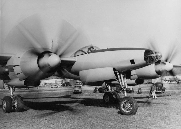
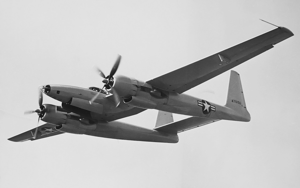
The Hughes XF-11 was an impressive and powerful aircraft intended for the photo-reconnaissance role. The eight-blade, contra-rotating propellers were over 15 ft (4.6 m) in diameter. Note the deployed flaps between the tail booms. (UNLV Libraries image)

The initial D-5 design was an enlarged D-2 and employed Duramold construction using resin-impregnated layers of wood, molded to shape under pressure and heat. The proposed aircraft had a 92 ft (28.0 m) wingspan, was 58 ft (17.7 m) in length, and weighed 36,400 lb (16,511 kg). The D-5 was powered by Pratt & Whitney (P&W) R-2800 engines and had a forecasted top speed of 488 mph (785 km/h) at 30,000 ft (9,144 m) and 451 mph (726 km/h) at 36,000 ft (10,973 m). A 4,000 lb (1,814 kg) bomb load could be carried in an internal bay. The AAF was still not interested in the aircraft and felt that HAC did not have the capability to manufacture such an aircraft in large numbers.

In early August 1943, Col. Elliot Roosevelt, President Franklin Roosevelt’s son, was in the Los Angeles inquiring with various aircraft manufacturers to find a photo-reconnaissance aircraft. Col. Roosevelt, who had previously commanded a reconnaissance unit, was hosted by Hughes and taken on a personal tour of the D-2. At the time, the aircraft was undergoing modification to become the D-5 and was not available for flight, but Col. Roosevelt was sufficiently impressed.

Hughes XF-11 no1 taxi

Howard Hughes taxies the first XF-11 out for its first and last flight. The nose of the aircraft accommodated a variety of camera equipment. Note the cowl flaps and the large scoops under the engine nacelles. (UNLV Libraries image)

General Henry “Hap” Arnold of the AAF was put under pressure from the White House to order the D-5 reconnaissance aircraft into production. To ease the AAF’s concerns about the D-5’s Duramold construction, the design was changed to metal wings and tail booms and only the fuselage built from Durmold. Arnold made the decision to order the D-5 aircraft “much against [his] better judgment and the advice of [his] staff.” The AAF issued a letter of intent on 6 October 1943 for the purchase of 100 examples of the D-5 reconnaissance aircraft. An official contract for the aircraft, designated F-11, was issued on 5 May 1944. Two aircraft would serve as prototypes with the remaining 98 aircraft as production versions.

As contracted, the Hughes XF-11 prototypes were of an all-metal construction and powered by two P&W R-4360 engines. The aircraft had the same layout as the Lockheed P-38 Lightning but was much larger. The fuselage consisted of a streamlined nacelle mounted to the center of the wing. At the front of the fuselage were provisions for photographic equipment. The cockpit was positioned just before the wing’s leading edge, and the cockpit was covered by a large, fixed bubble canopy. The pressurized cockpit could maintain an altitude of 10,500 ft (3,200 m) up an aircraft altitude of 33,500 ft (10,211 m). Entry to the cockpit was via a hatch and extendable ladder just behind the nose wheel landing gear well. The pilot’s seat was offset slightly to the left. Behind and to the right of the pilot sat a second crew member, who would fulfill the role of a navigator/photographer. The second crew member could crawl past the pilot and into the aircraft’s nose to service the cameras while in flight. The nose landing gear retracted to the rear and was stowed under the cockpit.

Hughes XF-11 no1 first flight

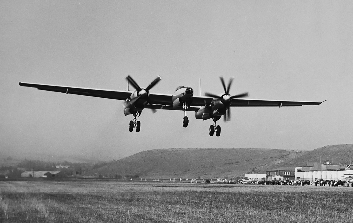
One of the very few images of the first XF-11 in flight as it takes off from Hughes Airport in Culver City, California on 7 July 1946. Note the rural background that is now completely developed. (UNLV Libraries image)

The XF-11’s wings had a straight leading and trailing edges, with the leading edge swept back approximately 6 degrees and the trailing edge swept forward around 3.5 degrees. Mounted to each wing about a third of the distance from the fuselage to the wing tip was the engine. The engine nacelle was slung under the wing and extended back to the aircraft’s tail. A large flap was located on the wing’s trailing edge between the tail booms. Each wing had an addition flap that extended from outside of the tail boom to near the wing tip. Relatively small ailerons spanned the approximate 66 in (1.68 m) distance from the flap to the wing tip. The aircraft’s main source of roll control were spoilers positioned on the upper surface of the outer wing and in front of the flap. Each wing incorporated a hardpoint outside of the tail boom for a 700 gallon (2,650 L) drop tank, and 600 gallon (2,271 L) jettisonable tip tanks were proposed but not included on the prototype aircraft.

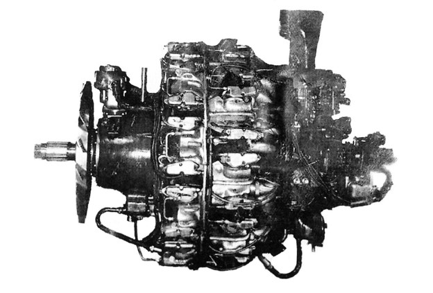
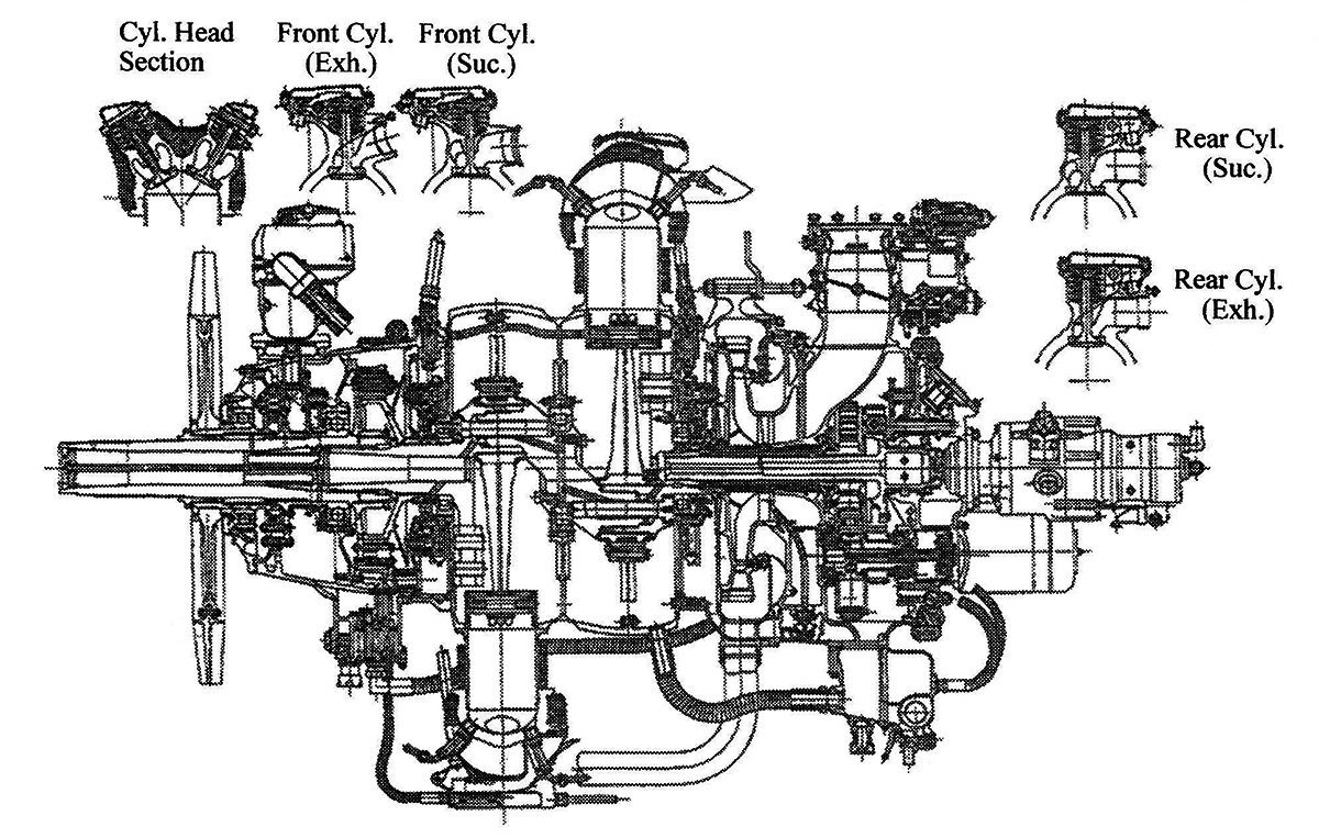
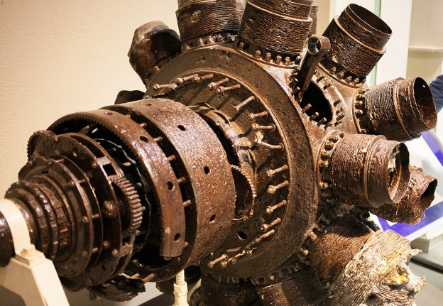
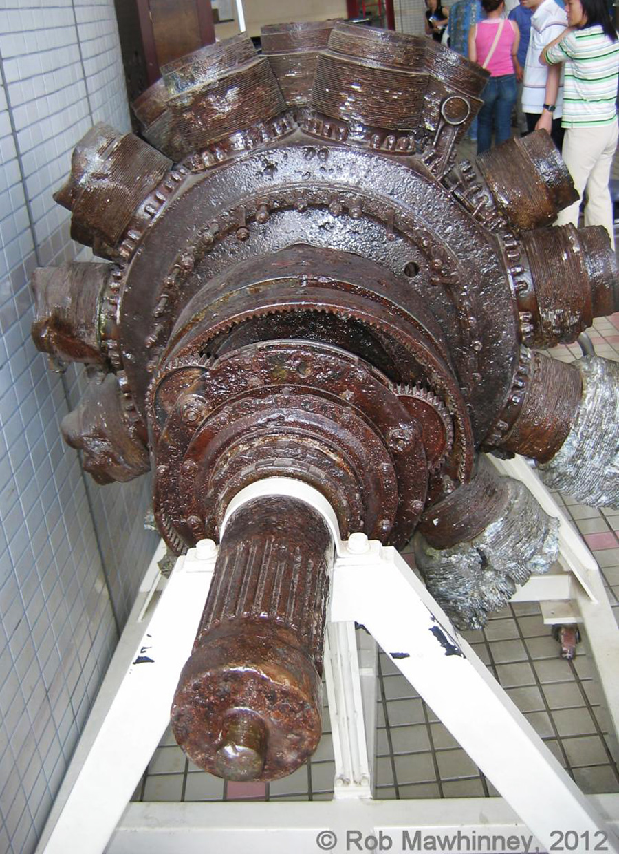
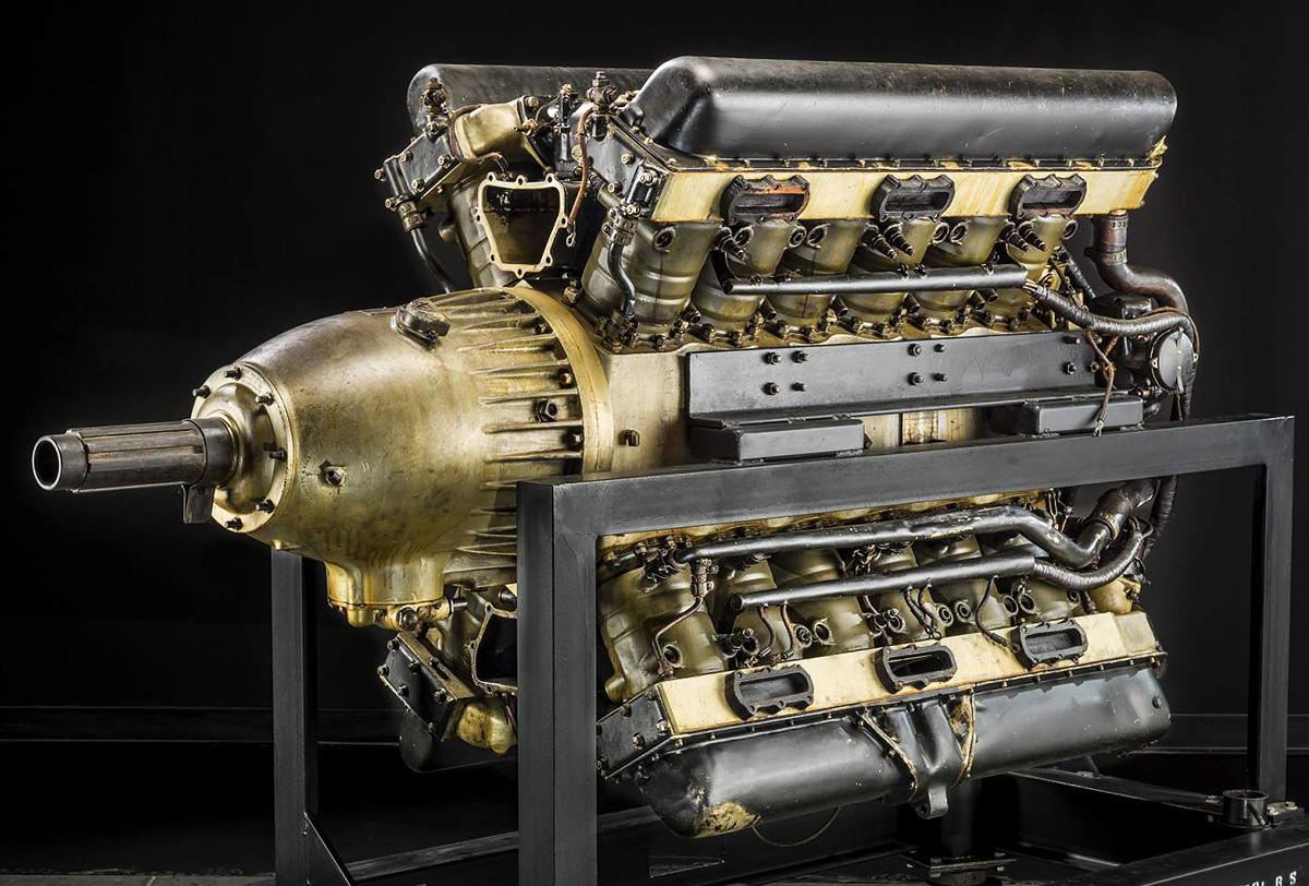
Each 3,000 hp (2,237 kW), 28-cylinder R-4360 engine was installed in the front of the wing and was housed in a streamlined cowling. Cowl flaps for engine cooling circled the sides and top of the cowling. Under the engine nacelle was a scoop that housed the oil cooler and provided air to the intercooler and the two General Electric BH-1 turbosuperchargers installed in each tail boom. Air that flowed through the oil cooler exited at the back of the scoop. Air that flowed through the intercooler was routed to an exit door on top of the engine nacelle, just above the wing’s leading edge. Exhaust from the superchargers was expelled from the sides of the engine nacelle, just under the wing. The turbosupercharger on the inner side of each tail boom could be shut down during cruise flight to take full advantage of the remaining turbosupercharger operating at its maximum performance. The main landing gear was positioned behind the engine and retracted to the rear into the tail boom. Attached to the end of each tail boom was a large, 11 ft 8 in (3.56 m) tall vertical stabilizer. Mounted in the 25 ft 8 in (7.82 m) space between the vertical stabilizers was the horizontal stabilizer. The left tail boom housed additional camera equipment behind the main landing gear well.

Hughes XF-11 no1 cockpit crash

The cockpit of the crashed XF-11 illustrates how lucky Hughes was to have survived. Hughes crawled out through the melted Plexiglas and was aided by residents who had witnessed the crash. Note the armored seat. The XF-11 had 350 lb (159 kg) of cockpit armor and self-sealing fuel tanks. (UNLV Libraries image)

The XF-11 had a wingspan of 101 ft 4 in (30.9 m), a length of 65 ft 5 in (19.9 m), and a height of 23 ft 3 (7.09 m). The aircraft had a top speed of 450 mph (725 km/h) at 33,000 ft (10,058 m) and 295 mph (475 km/h) at sea level. The XF-11 had a service ceiling of 42,000 ft (12,802 m), an initial climb rate of 2,025 fpm (10.3 m/s) and could climb to 33,000 ft (10,058 m) in 17.4 minutes. The aircraft had an empty weight of 39,278 lb (17,816 kg) and a maximum weight of 58,315 lb (26,451 kg). With its 2,105 gallon (7,968 L) internal fuel load, the XF-11 had a 5,000 mile (8,047 km) maximum range.

Delivery of the first XF-11 (44-70155) was originally scheduled for November 1944 with peak production of 10 aircraft per month being reached in March 1945—an ambitions timeline for any aircraft manufacturer. Delays were encountered almost immediately and gave credence to the AAF’s belief that HAC was not up to the task of designing and manufacturing aircraft for series production. By mid-1945, the XF-11 had still not flown, and the war was winding down. It was clear that the XF-11 would not be involved in World War II, and there was much doubt as to the usefulness of the aircraft post-war. As a result, the order for 98 production examples was cancelled on 26 May 1945, but the construction of the two prototypes was to proceed.

Hughes XF-11 no2 front

With the exception of its propellers, the second XF-11 was essentially the same as the first aircraft. The bulges on the nacelles under the wings were the exhaust outlets for the inner turbosuperchargers. (UNLV Libraries image)

The first XF-11 prototype was fitted with Hamilton-Standard Superhydromatic contra-rotating propellers. The front four-blade propeller was 15 ft 1 in (4.60 m) in diameter, and the rear four-blade propeller was 2 in (51 mm) longer at 15 ft and 3 in (4.65 m) in diameter. The impressive aircraft was finally finished by April 1946 and began taxi test. With Howard Hughes at the controls, an aborted high-speed taxi test on 15 April resulted in some minor damage and the need to rework some of the aircraft’s systems.

Once repaired, Hughes decided to make the XF-11’s first flight on 7 July 1946. The AAF had stipulated that the XF-11’s first flight should be no more that 45 minutes, the landing gear should not be retracted, the aircraft should stay near the airport and away from populated areas, communication should be established with the chase plane, and the flight should follow the plan discussed beforehand. While the flight was discussed with some, many involved with the aircraft were unaware of Hughes’ plans. Had his intentions been better known, someone may have reminded him about the propeller seal leak on the right engine. Hughes request 1,200 gallons (4,542 L) of fuel to be on board, which was twice as much as should be needed for the scheduled 45-minute flight. HAC’s Douglas A-20 Havoc would serve as a chase plane for the flight, but radio issues prevented communication between the two aircraft.

Hughes XF-11 no2 top

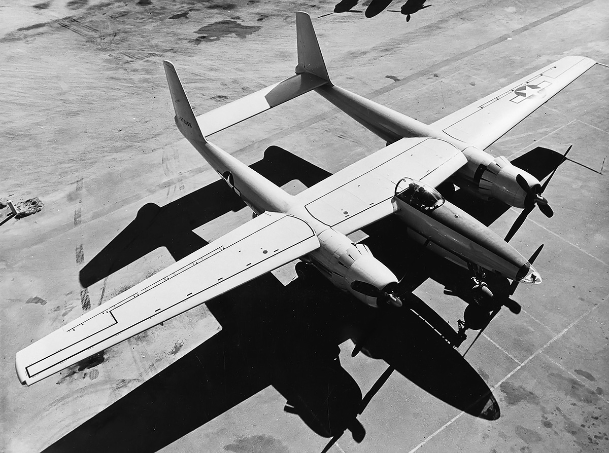
Top view of the second XF-11 illustrates the aircraft’s layout, which was similar to that of a Lockheed P-38. However, the XF-11 was a massive aircraft. Note that the rear of the fixed canopy has been removed. (UNLV Libraries image)

At around 5:20 PM, Hughes took the XF-11 off from Hughes Airport in Culver City, California on its maiden flight. Shortly after takeoff, Hughes retracted the gar, and the right main light remined illuminated, indicating a possible issue with the retraction. Hughes and the XF-11 flew out over the Pacific Ocean and turned back toward land. The landing gear was cycled several times during the flight in an attempt to resolve the perceived issue on account of the illuminated light.

After about an hour and 15 minutes, the oil supply in the right propeller was exhausted and the rear set of blades moved into a flat or reversed pitch. Had Hughes stuck to the 45-minute flight as the AAF ordered, the oil supply would not have been depleted. The reversed pitch propeller created a massive amount of drag on the right side of the aircraft. To the A-20 chase plane, it appeared that Hughes was maneuvering to land back at Culver City, some distance away. The chase plane broke formation to return to the airfield on its own. Had the two aircraft been in communication, the situation could have been discussed.

Hughes XF-11 no2 top rear

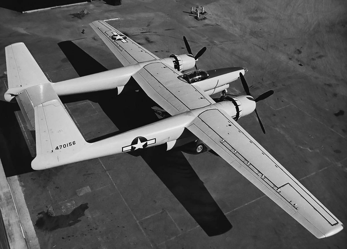
The trailing edge of the XF-11’s wing had a flap between the tail booms. Long flaps extended from the outer side of the tail booms almost to the wing tips. Note the relatively small ailerons at the wing tips. The wing spoilers are visible just in front of the outer flaps. (UNLV Libraries image)

Hughes, now alone, believed that the right main gear had deployed on its own and was causing the drag. Had Hughes left the gear down, he would have known the drag was a result of some other issue with the aircraft. Trying to keep the XF-11 straight resulted in the deployment of the left-wing spoilers, which further slowed the aircraft. Low, slow, and over a populated area, Hughes tried to make it to the open space of the Los Angles Country Club golf course in Beverly Hills. Landing short, the XF-11 crashed into four houses, broke apart, and caught fire. Hughes managed to pull himself from the wreckage, where he was helped further by neighborhood residents and arriving paramedics. Hughes suffers major injuries, including severe burns, at least 11 broken ribs, a punctured lung, and a displaced heart. Remarkably, he made a near-full recovery, but the incident started an addiction to codine, which would cause Hughes problems throughout the rest of his life.

Construction of the second XF-11 prototype (44-70156) continued after the accident. The second prototype used single rotation, four-blade propellers that were 14 ft 8 in (4.47 m) in diameter and made by Curtis Electric. Despite all of the new rules implemented because of his crash, Hughes was adamant that he pilot the first flight of the second XF-11 prototype. The AAF initially refused, but Hughes pressed the issue and made personal appeals to Lt.Gen. Ira Eaker and Gen. Carl Spaatz. Hughes also offered to put up a $5 million bond payable to the AAF if he crashed. With the posting of the bond, the AAF gave in. On 4 April 1947, Hughes flew the second XF-11 on its first flight, taking off from Hughes Airport. The flight was a personal victory for Hughes.

Hughes XF-11 no2 flight

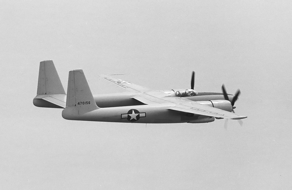
The second XF-11 on an early test flight. The aircraft was later fitted with spinners. Note the turbosupercharger’s exhaust just under the wing and the oil cooler’s air exit at the end of the scoop. (UNLV Libraries image)

The second XF-11 was later delivered to the AAF at Wright Field, Ohio in November 1947. After further flight tests, the aircraft went to Eglin Air Force Base in Florida. The XF-11 was noted for having good flight characteristics, but in-flight access of the camera equipment was extremely difficult and some of the aircraft’s systems were unreliable. In 1948, the aircraft was redesignated XR-11 in accordance to the new Air Force designation system. The XF-11 was tested at Eglin from December 1947 through July 1949.

Other, existing aircraft, mainly Boeing RB-29s and RB-50s, were serving in the reconnaissance role intended for the XF-11. These aircraft proved much less expensive than the XF-11, making the impressive and powerful XF-11 irrelevant. While the XF-11 probably could have done the reconnaissance job better, money was tight in the post-war years and there were other, more-promising projects to fund. The XF-11 was transferred to Sheppard Air Force Base in Wichita Falls, Texas on 26 July 1949 and subsequently served as a ground training aid, never flying again. The aircraft was struck from the Air Force’s inventory in November 1949 and was eventually scrapped.

Hughes XF-11 no2 1948

The second XF-11 sometime in 1948 with the revised (red stripe) Air Force insignia. The aircraft has recently taken off and the very large nose gear doors are just closing. Note the underwing pylons. (UNLV Libraries image)

Sources:
World’s Fastest Four-Engined Piston-Powered Aircraft by Mike Machat (2011)
R-4360: Pratt & Whitney’s Major Miracle by Graham White (2006)
Howard Hughes: An Airman, His Aircraft, and His Great Flights by Thomas Wildenberg and R.E.G. Davies (2006)
McDonnell Douglas Aircraft since 1920: Volume II by René J. Francillon (1990)
– “A Visionary Ahead of His Time: Howard Hughes and the U.S. Air Force—Part II” by Thomas Wildenberg, Air Power History (Spring 2008)
https://en.wikipedia.org/wiki/Hughes_XF-11

Mathis Vega 42 front

Mathis Vega 42-Cylinder Aircraft Engine

By William Pearce

Émile E. C. Mathis was a French automobile dealer who began manufacturing cars under his own name in 1910. Mathis was based in Strasbourg, which was part of Germany at the time. The Mathis automobile began to achieve success just before World War I. After the start of the war, Émile was conscripted into the German Army. Because of his knowledge of automobiles, the Germans sent Émile on a mission to Switzerland to purchase trucks and other supplies. Émile was given a substantial amount of money for the transaction, and he took the opportunity to desert the Germany Army and keep the funds. When Germany was defeated, Émile returned to his automobile company in Strasbourg, which was then in French territory near the German border, and resumed production.

Mathis Vega 42 front

The high-performance, 42-cylinder Mathis Vega aircraft engine. Note the camshaft-driven distributors attached to the front of each cylinder bank.

In 1937, the Mathis company began designing aircraft engines. A new company division, the Société Mathis Aviation (Mathis Aviation Company), was founded with offices in Paris and factories in Strasbourg and Gennevilliers. These were mostly the same facilities as the automobile business, with auto development out of Strasbourg and aircraft engine development centered in Gennevilliers, near Paris. Raymond Georges was the technical director in charge of the aircraft engines. The Mathis company started their involvement in aircraft engines with the rather ambitious Vega.

The origins of the Mathis Vega can be traced back to 1935, when the Ministère de l’Air (French Air Ministry) sought a high-power aircraft engine with cylinder bores of 4.92 in (125 mm) or less. The Vega was a 42-cylinder inline radial aircraft engine. The liquid-cooled engine had seven cylinder banks, each with six cylinders. The cylinder banks had an integral cylinder head and were made from aluminum. Steel cylinder barrels were screwed into the cylinder bank. Each cylinder had one intake valve and one sodium-cooled exhaust valve. A single overhead camshaft actuated the valves for each cylinder bank. The camshafts were driven from the front of the engine. Camshaft-driven distributors mounted to the front of each cylinder bank fired the two spark plugs in each cylinder. The spark plugs were positioned on opposite sides of the cylinder. The two-piece crankcase was made from aluminum.

At the front of the engine was a planetary gear reduction that turned the propeller shaft at .42 times crankshaft speed. At the rear of the engine was a single-speed and single-stage supercharger that turned at 5.53 times crankshaft speed. A single, two-barrel, downdraft carburetor fed fuel into the supercharger. Seven intake manifolds extended from the supercharger housing to feed the air/fuel mixture to the left side of each cylinder bank. Individual exhaust stacks were mounted to the right side of each cylinder bank. Attached to the back of the supercharger housing was a coolant water pump with seven outlets, one for each cylinder bank.

Mathis Vega 42 side

The Vega was a relatively compact engine. Note the exhaust port spacing on the cylinder banks. Presumably, different exhaust manifolds would be designed based on how the engine was installed in an aircraft.

The Vega had a 4.92 in (125 mm) bore and a 4.53 in (115 mm) stroke. The 42-cylinder engine displaced 3,617 cu in (59.3 L) and had a compression ratio of 6.5. The Vega was 42.1 in (1.07 m) in diameter and 59.8 in (1.52 m) long. The French Air Ministry was very enthusiastic about the Vega and paid for its development and the construction of two prototypes. The first Vega was known as the 42A, and the engine was first run in 1938. The 42A produced 2,300 hp (1,715 kW) at 3,000 rpm and 3,000 hp (2,237 kW) at 3,500 rpm. The engine weighed 2,756 lb (1,250 kg). Reportedly, two examples were built as well as a full-scale model. It is not clear how much testing was undertaken, but some sources indicate the engine was flown 100 hours in a test bed during 1939. Unfortunately, details of the engine’s testing and the aircraft in which it was fitted have not been found.

An improved version, the 42B, was under development when the Germans invaded in May 1940. The Vega engine program was evacuated from Gennevilliers and hidden in the Pyrenees mountains in southern France for the duration of the war. Believing that the Germans would not have forgotten his desertion and miss-appropriation of funds during World War I, Émile fled to the United States in 1940.

In 1941, Émile founded the Matam Corporation in New York, and Matam manufactured ammunition for the US Navy. In October 1942 Émile offered the Vega engine to the US Army Air Force (AAF) and indicated that he was in possession of the engine’s blueprints and that the prototype engine had been hidden in Lyon, France. Émile also stated that an unsupercharged version could equip speed boats for the US Navy. However, the AAF felt that attempting to obtain the engine or any of its components from France was impossible and that, with mass production of other engine types well underway, resources could be better allocated than undertaking the time-consuming process of converting the Vega to English measurements and planning production.

Mathis Vega 42 rear

Rear view of the Vega displays the intake manifolds, single carburetor, and the seven-outlet water pump. On paper, the Vega was a light and powerful engine, but no details have been found regarding its reliability.

After World War II, Émile returned to France, and work resumed on the Vega engine. The 42B was updated as the 42E (42E00). In all likelihood, the 42B and the 42E were the same engine; an example was exhibited in Paris, France in 1945. The Vega 42E produced 2,800 hp (2,088 kW) at 3,200 rpm with 8.5 psi (.59 bar) of boost for takeoff. The engine was rated for 2,300 hp (1,715 kW) at 3,000 rpm at 6,562 ft (2,000 m) and 1,700 hp (1,268 kW) at 2,500 rpm at 13,123 ft (4,000 m). The engine weighed 2,601 lb (1,180 kg).

The design of an enlarged Vega engine was initiated in 1942. Originally designated 42D, the larger engine was later renamed Vesta. The 42-cylinder Vesta was equipped with a two-speed supercharger that rotated 3.6 times crankshaft speed in low gear and 5.7 times crankshaft speed in high gear. The engine had a .44 gear reduction and utilized direct fuel injection. The Vesta had a 6.22 in (158 mm) bore, a 5.71 in (145 mm) stroke, and a displacement of 7,287 cu in (119.4 L). The engine had a takeoff rating of 5,000 hp (3,728 kW) at 2,800 rpm with 8.5 psi (.59 bar) of boost and a normal rating of over 4,000 hp (2,983 kW). The Vesta was 52.0 in (1.32 m) in diameter and weighed 4,519 lb (2,050 kg).

Like many other large engines built toward the end of World War II, the Vega failed to find an application, and the Vesta was never built. Mathis continued work on aircraft engines and produced a number of different air-cooled engines for general aviation. The design of these smaller engines was initiated during the war, and every attempt was made to maximize the number of interchangeable parts between the smaller engines. Some of the material for the smaller engines was liberated “scrap” provided by the Germans and intended for German projects. However, the general aviation engines were not made in great numbers, and production ceased in the early 1950s. No parts of the Vega engines are known to have survived.

Mathis Vega 42 R Georges

Raymond Georges overlooks the Vega engine mounted on a test stand in 1939. The pipes above the Vega are taking hot water from the engine.

Sources:
Les Moteurs a Pistons Aeronautiques Francais Tome 2 by Alfred Bodemer and Robert Laugier (1987)
Aircraft Engines of the World 1946 by Paul H. Wilkinson (1946)
L’aviation Francaise de Bombardement et de Renseignement (1918/1940) by Raymond Danel and Jean Cuny (1980)
– “The Mathis 42E 00” Flight (6 September 1945)
http://www.enginehistory.org/Piston/French/Mathis42/Mathis42.shtml
https://sites.google.com/site/moteursmathis/
https://ww2aircraft.net/forum/threads/mathis-vega-42-cylinder-french-aero-engine.49170/

Hughes XH-17 hover front

Hughes (Kellett) XH-17 Heavy-Lift Helicopter

By William Pearce

On 31 January 1946, the Unites States Army Air Force issued a Request for Proposal involving the design of a heavy-lift helicopter capable of transporting a 10,000 lb (4,536 kg) external load. Additional specifications include the use of jet turbine propulsion and rotors equipped with tip jets. The Kellett Aircraft Corporation of Upper Derby, Pennsylvania was awarded a design contract on 2 May 1946, and the new helicopter was designated XR-17. If all went well with the XR-17’s design, a contract to build a test rig would be issued.

Hughes XH-17 side

The massive Hughes XH-17 sits at rest before its first public flight on 23 October 1952. The notches in the rotor blade are where jets of pressurized air exit the rotor. (LIFE image via Google)

Kellett moved forward with the XR-17 design, which was centered around a pair of 4,000 lbf (17.79 kN) General Electric J35 (TG-180) engines driving a two-blade rotor. However, the engines were not mechanically attached to the rotors. Air was bled off from the compressor section of the modified engines and was ducted through the hollow rotors. The 400°F (204°C) air was exhausted from each rotor via four pressure-jets in the tip’s trailing edge. The jet of air emanating from the rotor tips caused the rotors to turn. This propulsion system was referred to as cold-cycle pressure-jet, because the air from the engine’s compressor section was much cooler than the air from the engine’s exhaust. To further augment power, General Electric GE33F pressure-jet burners sprayed and ignited fuel into the jet of air exiting the rotor. Kellett estimated that 1,000 hp (746 kW) was produced with the cold-cycle air jet alone, and 3,480 hp (2,595 kW) was produced with the tip burners in use.

By 27 August 1947, the XR-17 design had progressed well, and Kellett was awarded a contract to produce a test rig of the helicopter’s rotor system. Kellett went to work constructing the test rig and tried to save money wherever possible by using components of other aircraft. The company was having financial issues, and the XR-17 project had an uncertain future.

Hughes XH-17 group

From left to right: Rea Hopper, Howard Hughes, Clyde Jones, Warren Reed, Colonel Carl Jackson, Gale Moore, Chalmer Bowen, and Marion Wallace. (LIFE image via Google)

In June 1948, the helicopter was redesignated XH-17. Through 1948, work continued on the XH-17 test rig, but the financial issues at Kellett only worsened. With the Air Force’s blessing, Hughes Aircraft purchased the XH-17 project and moved all materials and many Kellett personnel to Culver City, California. Work on the XH-17 resumed in March 1949 and progressed rapidly with full support from Hughes.

The Hughes XH-17 consisted of a cockpit from a Waco CG-15 glider attached to a custom-built tube steel frame. Its steerable front landing gear was made using the main wheels from a North American B-25 Mitchell, and its rear landing gear was made using the main wheels from a Douglas C-54 Skymaster. The XH-17’s fuel tank was originally a 636-gallon (2,408-L) extended-range bomb bay tank for a Boeing B-29 Superfortress. The helicopter’s 130 ft (39.62 m) two-blade main rotor turned at 88 rpm. Each blade was 12 in (.30 m) thick, 58 in (1.47 m) wide, and weighed 5,000 lb (2,268 kg). The large pressure-jet rotors had a very short fatigue life.

Hughes XH-17 rear

Rear view of the XH-17 illustrating the helicopter’s tube frame construction and relatively small tail rotor. (LIFE image via Google)

The XH-17 test rig was run for the first time around October 1949. Only bleed air was used to turn the rotors. After about three months of testing, the rotor burners were fired for the first time on 22 December 1949. This created a very a loud whop-whop-whop noise that coincided with the passing of each set of lit burners on the rotors’ tips. The noise was so loud that it could be heard eight miles (13 km) away, and the XH-17 caused numerous noise complaints to be filed against Hughes.

Hughes XH-17 front


The XH-17’s wide stance was to facilitate positioning equipment under the helicopter. Note the large horn balance on the rotor’s leading edge. The stress and vibration of operating the 130 ft (39.62 m) rotor gave the blades a very short life. (LIFE image via Google)

Testing of the rig steadily progressed until June 1950, when a control link broke and caused the XH-17 test rig to rise about 10 feet (3 m) off the ground before it crashed back down. The rig was damaged, but the rotors and power system were unharmed. Rather than just rebuild the test rig, the decision had already been made to convert the rig into a flight-capable helicopter. Numerous systems were revised, and a tail rotor from a Sikorsky H-19 Chickasaw was added. The tail rotor was small compared to the rest of the XH-17. The rotor jets did not create a major torque reaction that needed to be counteracted like the main rotors of a conventional helicopter. The tail rotor was mainly for differential directional control. The wide-set and tall landing gear allowed loads to be driven under the helicopter and then attached for lifting.

The XH-17 was ready for flight in the summer of 1952. The complete helicopter was 53 ft 4 in (16.55 m) long and 30 ft 2 in (9.17 m) tall. The XH-17 had an estimated top speed of 90 mph (145 km/h) and a range of only 40 miles (64 km), due to the high fuel consumption of the rotor’s pressure-jet burner system. The helicopter had a normal weight of around 41,700 lb (18,915 kg) and a maximum weight with a 10,284 lb (4,665 kg) payload of 52,000 lb (23,587 kg).

Hughes XH-17 hover front

The XH-17 was a rather awkward-looking machine, and it is easy to see why it was referred to as “Monster.” The glowing spots on the rotor blade’s tip are the pressure-jet burners. (LIFE image via Google)

During a test on 16 September 1952, the XH-17 made its first unofficial flight. Piloted by Gale Moore and Chalmer Bowen, the helicopter was accidently bounced off the ground during a hover test due to overly-sensitive controls. The controls were modified, and a much more controlled hover was established the following day. The XH-17 made its public debut on 23 October 1952 at Hughes Airport in Culver City. Two flights were made that day, and the XH-17 hovered, flew forward up to 45 mph (72 km/h), flew backward, and rotated 360 degrees. Moore and Bowen were again the pilots and were joined by Marion Wallace. They had nicknamed the XH-17 “Monster” on account of its odd appearance, but the helicopter was also known as the “Flying Crane.”

As the XH-17 program was progressing, the Air Force asked Hughes to design an improved and more powerful version in October 1951. The new helicopter was designated XH-28 and would use a cold-cycle rotor system with pressure-jet burners, similar to the arrangement on the XH-17 but with four blades. Power was provided by two Allison XT40-A-8 turboprop engines. Each 5,300 hp (3,952 kW) XT40 engine consisted of two T38 engines coupled to a common gear reduction. The engines in the XH-28 would drive a compressor unit to send air to the rotors. The XH-28 would weigh 52,000 lb (23,587 kg) empty and would be capable of lifting 50,000 lb (22,680 kg), for a total gross weight of 105,000 lb (47,627 kg). The Air Force awarded a design contract for the XH-28 to Hughes in January 1952.

Hughes XH-17 hover side

The blades of the XH-17 operating at 88 rpm were easily distinguished, even when the helicopter was in flight. Note the glow of the tip burners and the size of the GE J35 engine. (LIFE image via Google)

A XH-28 mockup was constructed, and extensive testing was involved to create rotors with an extended fatigue life. Ultimately, rotors of a bonded titanium construction were chosen. Allison was hesitant to devote engineering resources to the engine design because the company was involved with so many other projects that it felt held more promise. In December 1952, the Air Force decided that its funds should be spent on jet fighters and bombers and that it would not support the XH-28 beyond 1953. The Air Force was willing to hand the project over to the Army, which was interested in the XH-28 as a way to transport tanks and other equipment. However, the Army soon decided that its funds would be better spent on smaller and less expensive helicopters and never took over the XH-28 project. On 17 August 1953, the Air Force cancelled the XH-17 and XH-28.

XH-17 flight testing progressed sporadically over three years. Later flights pushed the helicopter’s speed up to 70 mph (113 km/h) and altitude to 350 ft (107 m). The XH-17 made 33 flights for a total of 10 hours flying time. Flight tests were halted in December 1955 on account of the rotor blades reaching their fatigue life. On the XH-17’s last flight, the helicopter carried an 8,000 lb (3,629 kg) communication trailer, which pushed the XH-17’s gross weight to over 50,000 lb (22,680 kg) for the flight. At the time, the XH-17 was the world’s largest helicopter and could carry more than any other helicopter. Its 130 ft (39.62 m) rotor system is still the largest ever used. However, the XH-17’s noisy operation and short range limited its usefulness. The XH-17 and the XH-28 mockup and parts were eventually scrapped.

Hughes XH-28 mockup

Full-scale mockup of the Hughes XH-28, which was planned as a larger, more capable heavy-lift helicopter than the XH-17. Vehicles could be driven onto the platform and secured, eliminating the need for the load to be suspended from the helicopter. (LIFE image via Google)

Sources:
McDonnell Douglas Aircraft since 1920: Volume II by René J. Francillon (1990)
Howard’s Whirlybirds by Donald J. Porter (2013)
Howard Hughes: An Airman, His Aircraft, and His Great Flights by Thomas Wildenberg and R.E.G. Davies (2006)
http://www.1000aircraftphotos.com/Contributions/VanTilborg/3138.htm

Studebaker’s XH-9350 and Their Involvement with Other Aircraft Engines

By William Pearce

Before the United States entered World War II, the Army Air Corps conceptualized a large aircraft engine for which fuel efficiency was the paramount concern. It was believed that such an engine could power bombers from North America to attack targets in Europe, a tactic that would be needed if the United Kingdom were to fall. This engine project was known as MX-232, and Studebaker was tasked with its development. After years of testing and development, the MX-232 program produced the Studebaker XH-9350 engine design.

Although a complete XH-9350 engine was not built, Studebaker’s XH-9350 and Their Involvement with Other Aircraft Engines details the development of the MX-232 program and the XH-9350 design. In addition, the book covers Studebaker’s work with other aircraft engines: the power plant for the Waterman Arrowbile, their licensed production of the Wright R-1820 radial engine during World War II, and their licensed production of the General Electric J47 jet engine during the Korean War.

Contents:

Preface
1. Studebaker History
2. Waldo Waterman and the Arrowbile
3. Studebaker-Built Wright R-1820 Cyclone
4. XH-9350 in Context
5. XH-9350 in Development
6. XH-9350 in Perspective
7. Studebaker-Built GE J47 Turbojet
Conclusion
Appendix: MX-232 / XH-9350 Documents
Bibliography
Index

$19.99 USD
Softcover
8.5 in x 11 in
214 pages (222 total page count)
Over 185 images, drawings, and tables, and over 75,000 words
ISBN 978-0-9850353-1-0

Studebaker’s XH-9350 and Their Involvement with Other Aircraft Engines is available at Amazon.com. If you wish to purchase the book with a check, please contact us for arrangements.

Sample Pages:
         

Hitachi Nakajima Ha-51 side

Hitachi/Nakajima [Ha-51] 22-Cylinder Aircraft Engine

By William Pearce

In December 1942, the Imperial Japanese Army (IJA) sought a new radial aircraft engine capable of more than 2,500 hp (1,864 kW). At the time, the most powerful Japanese production engines produced around 1,900 hp (1,417 kW). The new engine was given the IJA designation Ha-51 and was later assigned the joint Japanese Army and Navy designation [Ha-51]. However, the Imperial Japanese Navy did not show any interest in the engine.

Hitachi Nakajima Ha-51 side

The 22-cylinder Hitachi/Nakajima [Ha-51] engine had a general similarity to the Nakajima [Ha-45]. Note the cooling fan on the front of the engine and the dense nature of the cylinder positioning.

Some sources state that Nakajima was tasked to develop the new [Ha-51] engine, while other sources contend that Hitachi was in charge of the engine from the start. Both Nakajima and Hitachi had produced previous engines with the same bore and stroke as the [Ha-51]. However, the [Ha-51] shares some characteristics, such as fan-assisted air cooling, with other Nakajima engines. Regardless, development of the [Ha-51] was eventually centered at the Hitachi Aircraft Company (Hitachi Kikuki KK) plant in Tachikawa, near Tokyo, Japan. The Hitachi Aircraft Company was formed in 1939 when the Tokyo Gas & Electric Industry Company (Tokyo Gasu Denki Kogyo KK, or Gasuden for short) merged with the Hitachi Manufacturing Company.

The [Ha-51] was a 22-cylinder, two-row radial engine. Its configuration of 11-cylinders in each of two rows was only common with two other engines: the Mitsubishi A21 / Ha-50 and the Wright R-4090. Although the three engines were developed around the same time, it is not believed that any one influenced the others. Moving from nine cylinders in each row to 11 was a logical step for producing more power without increasing a radial engine’s length. The tradeoff was accepting the increased frontal area of the engine and additional strain on the crankpins.

The engine’s three-piece crankcase was made of steel and split vertically along the cylinder center line. The crankcase bolted together via internal fasteners located between the cylinder mounting pads. The cylinders consisted of an aluminum head screwed and shrunk onto a steel barrel. Each cylinder had one intake valve and one exhaust valve. The valves were inclined at a relatively narrow angle of around 62 degrees. The intake and exhaust ports for each cylinder faced the rear of the engine. The cylinders had a compression ratio of 6.8. The second row of cylinders was staggered behind the first row. Only a very narrow gap existed between the front cylinders to enable cooling air to the rear cylinders. Baffles were used to direct the flow of cooling air.

Hitachi Nakajima Ha-51 drawing

Drawing of the [Ha-51] with details of the cylinder intake and exhaust valves. The angle between the intake and exhaust valves was fairly narrow for a radial engine, a necessity to fit 11 cylinders around the engine while keeping its diameter as small as possible.

A single-stage, two-speed supercharger was mounted to the rear of the [Ha-51]. The supercharger’s impeller was 13 in (330 mm) in diameter and turned at 6.67 times crankshaft speed in low gear and 10.0 times crankshaft speed in high gear. Fuel was fed into the supercharger by a carburetor. At the front of the engine was a planetary gear reduction that used spur gears to turn the propeller at .42 times crankshaft speed. A cooling fan driven from the front of the gear reduction was intended to keep engine temperatures within limits once the [Ha-51] was installed in a close-fitting cowling.

The [Ha-51]’s fan-assisted cooling system was originally developed for the 1,900 hp (1,417 kW) Nakajima [Ha-45] Homare engine, which gives some credence to Nakajima being involved with the [Ha-51]. The [Ha-45] and the [Ha-51] also had the same bore and stroke. Nearly all Gasuden/Hitachi radial engines had a single row of nine-cylinders and produced no more than 500 hp (373 kW). Developing a two-row, 22-cylinder, 2,500 hp (1,864 kW) engine would be a significant jump for Hitachi, but much less so for Nakajima.

The [Ha-51] had a 5.12 in (130 mm) bore and a 5.91 in (150 mm) stroke. Its total displacement was 2,673 cu in (43.8 L). The engine had an initial rating of 2,450 hp (1,827 kW) at 3,000 rpm and 8.7 psi (.60 bar) of boost for takeoff, and 1,950 hp (1,454 kW) at 3,000 rpm with 7.7 psi (.53 bar) of boost at 26,247 ft (8,000 m). However, planned development would increase the [Ha-51]’s output up to 3,000 hp (2,237 kW). The engine was 49.4 in (1.26 m) in diameter, 78.7 in (2.00 m) long, and weighed 2,205 lb (1,000 kg).

Construction of the first [Ha-51] prototype was started in March 1944. Testing of the completed engine revealed high oil consumption and issues with bearing seizures between the crankpins and master rods. The gear reduction and cooling fan drive experienced failures, and difficulty with the supercharger led to broken impellers. Due to these issues, the engine was unable to pass a 100-hour endurance test. Three [Ha-51] engines and parts for a fourth had been built when the prototypes were damaged during a US bombing raid on the factory at Tachikawa in April 1945. Combined with the current state of the war, the setback caused by the air raid signaled the end of the [Ha-51] project. When US troops inspected the Tachikawa plant in late 1945, they found the three damaged and partially constructed [Ha-51] engines. One engine was mostly complete but lacked its supercharger section. Reportedly, this engine was reassembled by order of the US military, but no further information regarding its disposition has been found. All [Ha-51] engines were later scrapped, and no parts for them are known to exist.

Hitachi Nakajima Ha-51 rear

Rear view of a [Ha-51] engine as found by US troops at Hitachi’s Tachikawa plant. The engine was fairly complete, with the exception of the supercharger and accessory section. This engine was reportedly reassembled at the request of the US military.

Sources:
Japanese Aero-Engines 1910–1945 by Mike Goodwin and Peter Starkings (2017)
– “The Radial 22 Cylinder Engine “HA51” and Genealogic Survey of the Gas-Den Aero-Engine” by Takashi Suzuki, Kenichi Kaki, Toyohiro Takahashi, and Masayoshi Nakanishi Transactions of the Japan Society of Mechanical Engineers (Part C) Vol. 74, No. 746 (October 2008)
– “Hitachi Aircraft Company” The United States Strategic Bombing Survey, Corporation Report No. VII (February 1947)
http://www.enginehistory.org/Piston/Japanese/japanese.shtml
https://ja.wikipedia.org/wiki/ハ51_(エンジン)

Mitsubishi Ha-50 campns

Mitsubishi A21 / Ha-50 22-Cylinder Aircraft Engine

By William Pearce

Mitsubishi Heavy Industries was Japan’s largest aircraft engine producer and had developed a number of reliable and powerful engines. During 1942, Mitsubishi investigated a 3,000 hp (2,237 kW) engine design. Given the designation A19, the radial engine design had four rows of seven cylinders. The A19 had a 5.51 in (140 mm) bore and a 6.30 in (160 mm) stroke. This gave the 28-cylinder engine a displacement of 4,208 cu in (69.0 L). However, in the spring of 1943, Mitsubishi engineers concluded after extensive testing that the rear rows of the engine would not have enough airflow for sufficient cooling. The A19 was never built.

Mitsubishi Ha-50 campns

Although in a sorry state, the Mitsubishi A21 / Ha-50 preserved at the Museum of Aviation Science in Narita, Japan gives valuable insight into a lost generation of Japanese aircraft engines and 22-cylinder aircraft engines. Nearly all of the non-steel components have rotted away. (campns.jp image)

To solve the cooling issues, Mitsubishi turned to a two-row radial engine design with 11-cylinders per row. The new engine carried the Mitsubishi designation A21. The Imperial Japanese Army (IJA) approved of the engine design and instructed Mitsubishi to proceed with construction. The A21 was given the IJA designation Ha-50. Many sources state the engine was later assigned the joint Japanese Army and Navy designation [Ha-50]. However, [Ha-52] would have been more fitting for the engine’s configuration, and the [Ha-50] designation may be the result of confusion with the IJA’s Ha-50 designation. The Imperial Japanese Navy (IJN) was not involved with the engine’s development.

At the time, Mitsubishi was already developing an 18-cylinder radial based on their 14-cylinder [Ha-32] Kasei engine. To speed development of the Ha-50, Mitsubishi decided to continue the practice of adding additional Kasei-type cylinders to a new crankcase. The resulting air-cooled, 22-cylinder, two-row, radial configuration was common with only two other engines: the Hitachi/Nakajima [Ha-51] and the Wright R-4090. Using two rows of 11 cylinders kept the engine short and relatively simple compared to a four-row configuration. The two-row configuration also enabled a rather straightforward engine cooling operation without resorting to complex baffles. However, the large number of cylinders in each row increased the engine’s frontal area and caused greater stresses on the crankshaft’s crankpins.

Mitsubishi Ha-50 side

The Ha-50 had a substantial amount of space between the first and second cylinder rows. Note the pistons frozen in their cylinders. (Rob Mawhinney image via the Aircraft Engine Historical Society)

The Ha-50 used a three-piece, steel crankcase that was split vertically along the cylinder center line and secured via internal fasteners. Aluminum alloy housings were used for the gear reduction and the supercharger. Each cylinder was secured to the crankcase by 16 studs. The cylinders were formed with a cast aluminum head screwed and shrunk onto a steel barrel. Relatively thin fins were cut into the steel cylinder barrels to aid cooling. Each cylinder had one intake valve and one exhaust valve. The intake and exhaust ports for each cylinder faced toward the rear of the engine. The cylinders had a compression ratio of 6.7. Following the typical two-row radial configuration, the second row of cylinders was staggered behind the first row. Ample space existed between the cylinders in the front row for cooling air to reach the cylinders in the rear row. A fairly large space existed between the front and rear cylinder rows, perhaps signifying a rather robust center crankshaft support.

Two-stage supercharging was used in the form of a remote turbosupercharger for the first stage and a gear-driven, two-speed supercharger for the second stage. However, the test engines had only the gear-driven supercharger, which turned at 7.36 times crankshaft speed in low gear and 10.22 times crankshaft speed in high gear. The Ha-50 used fuel injection, and water-injection was available to further boost power. At the front of the engine was a planetary gear reduction that turned the propeller at .412 times crankshaft speed. Some sources state that contra-rotating propellers were to be used, but only a single propeller shaft was provided on the initial engines. A cooling fan was driven from the front of the gear reduction.

Mitsubishi Ha-50 cylinders

Left—An Ha-50 aluminum cylinder head still attached to the cylinder barrel. Note the valve in the intake port. Right—Detailed view of a cylinder barrel illustrates the cooling fins cut into its middle and the threaded portion at the top for cylinder head attachment. (Rob Mawhinney images via the Aircraft Engine Historical Society)

The Ha-50 had a 5.91 in (150 mm) bore and a 6.69 in (170 mm) stroke. Its total displacement was 4,033 cu in (66.1 L). The engine had a takeoff rating of 3,100 hp (2,312 kW) at 2,600 rpm and 8.7 psi (.60 bar) of boost. Normal ratings for the engine were 2,700 hp (2,013 kW) at 4,921 ft (1,500 m) and 2,240 hp (1,670 kW) at 32,808 ft (10,000 m). The normal ratings were achieved at an engine speed of 2,500 rpm and with 5.8 psi (.40 bar) of boost. The Ha-50 was 56.9 in (1.45 m) in diameter, 94.5 in (2.40 m) long, and weighed 3,395 lb (1,540 kg).

Mitsubishi Ha-50 front

Front view of the Ha-50 illustrates the ample space between the front-row cylinders, enabling air to reach the rear-row cylinders. Note the single rotation propeller shaft. (Rob Mawhinney image via the Aircraft Engine Historical Society)

Construction of the Ha-50 started in April 1943, and the first engine was completed in 1944. Engine testing began immediately, and severe vibrations were encountered that reportedly shook one engine apart on the test stand. Some sources indicate the Ha-50 was an optional power plant for the Kawanishi TB, a four-engine transoceanic bomber ordered by the IJA. The Kawanishi TB was a smaller and lighter competitor to the Nakajima Fugaku, which had become exclusively an IJN project. Six Ha-50 engines were ordered for the Kawanishi TB, but the bomber project was cancelled before any aircraft were built. Three of the Ha-50 engines were finished, but their operational issues and the cancelling of the Kawanishi TB resulted in the Ha-50 engine project being abandoned. Two of the engines were damaged in a bombing raid, but the surviving Ha-50 reportedly achieved 3,200 hp (2,386 kW) in July 1945.

The three Ha-50 engines were thought to have been destroyed at the end of World War II and before the arrival of US forces. However, one Ha-50 engine was discovered in November 1984 during expansion work at the Haneda Airport (Tokyo International Airport). Some sources indicate the surviving engine was found by US forces shortly after the war and delivered to Haneda Airport for later shipment to the United States. Apparently, plans changed, and the engine was subsequently bulldozed into a pit and covered with dirt. The discovered Ha-50 was in an advanced state of decay, but it was recovered, and efforts were made to preserve the engine and prevent its continued deterioration. The engine’s condition was stabilized, and it was put on display at the Museum of Aviation Science in Narita, Japan. The surviving Ha-50 is the sole example of any 22-cylinder aircraft engine.

Mitsubishi Ha-50 rear

The supercharger and accessory case completely rotted off the Ha-50 during its near 40-year interment. Note the threads cut into the top of the steel cylinder barrels. (Rob Mawhinney image via the Aircraft Engine Historical Society)

Sources:
Japanese Aero-Engines 1910–1945 by Mike Goodwin and Peter Starkings (2017)
The History of Mitsubishi Aero-Engines 1915–1945 by Hisamitsu Matsuoka (2005)
http://www.arawasi.jp/on%20location/narita1.html
https://ja.wikipedia.org/wiki/ハ50_(エンジン)

Smith Enterprise tow

Fred H. Stewart Enterprise (Smith-Harkness) LSR Car

By William Pearce

In 1930, Australian driver Norman Leslie “Wizard” Smith attempted to set a Land Speed Record (LSR) on Ninety Mile Beach (which is actually 55 miles / 88 km long) in New Zealand. His car, the Anzac, was built by well-known race driver, engineer, and fellow Australian, Donald James Harkness. Harkness was also the riding mechanic for the Anzac record runs. Smith and Harkness knew the 360 hp (268 kW) Anzac was not capable of setting an absolute speed record for the flying mile (1.6 km), but they hoped to set national records for Australia and New Zealand as well as a 10-mile (16-km) world record. Technically they were successful, but the 10-mile (16-km) record was not verified on account of a single run being made without a return run in the opposite direction. The Anzac was also used to gain experience that would be applied to the design and construction of a much more powerful car capable of 300 mph (483 km/h).

Smith Enterprise Harkness

Norman “Wizard” Smith and Don Harkness pose with the nearly completed Fred H. Stewart Enterprise in 1931. Note how the body sloped up in front of the cockpit. This was done in an attempt to increase downforce at the center of the car to aid stability at high speeds.

Setting world speed records is an expensive endeavor. While Smith and a few friends funded most of the Anzac, the much larger and faster LSR car would need financial resources beyond that which Smith and his partners could provide. Fortunately, Smith was able to leverage his success with the Anzac and as a racer to gain the financial backing of Australian businessman and politician Frederick Harold Stewart. The one stipulation set by Stewart was that the new LSR car be named the Fred H. Stewart Enterprise. The car was originally to be named Anzac II, but at the time, Australian policy stated that ANZAC can only refer to the Australian and New Zealand Army Corps and cannot be used in any other fashion without prior permission. As a result, Smith had to take the name off his previous racer and select a different name for the new racer. The financing terms were agreed upon, and Smith and Harkness focused on building the LSR car, the Fred H. Stewart Enterprise (Enterprise).

To power the Enterprise, Smith and Harkness needed an engine much more powerful than anything they could obtain themselves. They sought a 1,600 hp (1,193 kW) Rolls-Royce R engine developed for the 1929 Schneider Trophy contest. The Enterprise team turned to the Australian government for assistance, and the Australian Prime Minister, James Scullin, reached out to the British government. Ultimately, the British Air Ministry loaned Smith the latest Napier Lion VIID W-12 engine, capable of 1,450 hp (1,081 kW) at 3,600 rpm. This was the same type of engine that Malcolm Campbell would soon install in his latest Blue Bird revision, the Campbell-Napier-Railton Blue Bird. At the time, the engine’s particulars were considered secret, and the Air Ministry stipulated that only Smith, Harkness, and two Enterprise crew members be allowed to work on it. Some reports indicate that a deposit of £5,000 was required, which was paid by Stewart, and that a Rolls-Royce engine was expected right up until the crate was opened to reveal the Napier. The taller and less-powerful Lion necessitated a slight redesign of the Enterprise, and the car’s estimated top speed decreased to 280 mph (451 km/h).

Smith Enterprise build

The Enterprise under construction at Harkness & Hillier Engineering Works. Smith is sitting, with Harkness at his right. In front of the Napier Lion engine is Smith’s wife, Harriet. Note the screw jacks at the rear of the car, the leaf-spring rear suspension, and the size of the frame rails.

The Fred H. Stewart Enterprise was designed by Harkness and built at the Harkness & Hillier Engineering Works in Five Dock, near Sydney. The car resembled the 930 hp (694 kW) Irving-Napier Golden Arrow, which Henry Segrave had used to set the then-current LSR at 231.362 mph (372.341 km/h) on 11 March 1929. Like the Golden Arrow, the Enterprise had a chisel-shaped front end leading to a tightly-cowled Lion engine. Its wheels were set outside of the bodywork, and the cockpit was positioned toward the rear and flanked by driveshafts connected to the rear axle. One major difference in appearance was that the Enterprise had two stabilizing tails, each extending back behind the rear wheels. With an additional 520 hp (388 kW) and 17-percent less frontal area, Smith and Harkness thought the Enterprise would go faster than the Golden Arrow.

The Enterprise’s chassis consisted of two large frame rails connected by various cross members. Each corner of the frame had provisions for a screw jack to easily raise the car. The Lion engine was nestled between the frame rails and connected to a three-speed transmission. Output from the transmission was split into two drive shafts that passed through armor-plated housings on both sides of the driver’s seat. Each drive shaft connected to a drive box that was connected to a rear wheel. The front wheels appear to have had very minimal suspension, and the rear wheels were supported by leaf springs positioned above the frame. The frame, powertrain, and suspension were all designed to minimize the Enterprise’s height.

Smith Enterprise debut

At its christening on 26 October 1931, the Enterprise was fitted with relatively small aerodynamic fairings behind the rear wheels. It is not clear if this was Harkness’ final vision for the car, as other photos show no front fairings at all.

Separate drag links extended from the steering box positioned in front of the cockpit to the front wheels. A tie rod connected the front wheels together. The steering system enabled 20 degrees of wheel movement. A close-fitting body covered the Enterprise. The body was designed to push the middle of the car down at high speeds. A hump on each side of the cockpit enclosed the suspension for the rear wheels. The humps tapered down to form a wedge at the rear of the car. The body surrounding the cockpit tapered back to a point. The stabilizing tail fins, built from steel tube frames and covered with fabric, extended behind the rear wheels. A flat-plate windscreen was mounted at an angle just before the cockpit, and the fuel tank was positioned behind the cockpit.

The Enterprise was 26 ft (7.92 m) long, 69 in (1.75 m) wide, 36 in (.91 m) tall in front of the cockpit, 42 in (1.07 m) tall at the top of the cockpit, and 48 in (1.22 m) tall at the tail fins. The car had 7.5 in (191 mm) of ground clearance and weighed around 6,700 lb (3,039 kg). Only the rear wheels had provisions for brakes. Smith purchased a set of special Dunlap slicks guaranteed to 310 mph (500 km/h) for the speed runs. These tires were 37 in (940 mm) tall and 7 in (178 mm) wide. Like Smith’s Anzac, the Enterprise was finished in a golden color and had Australian flags painted on its tails. While the Enterprise was being built, Campbell set a new flying-mile (1.6-km) LSR at 245.736 mph (395.474 km/h) on 5 February 1931.

Smith Enterprise tow

The Enterprise without any front wheel fairings and with Smith in the cockpit. As designed, the Enterprise was a rather sleek machine. Note the brake link extending from the cockpit back to the rear wheel and the lack of brakes on the front wheels.

The Enterprise was anticipated to be completed around February 1931. However, delays with the car’s construction along with separate business matters preoccupying Smith, Harkness, and everyone else involved with the car, resulted in the Enterprise not being completed until the end of 1931. During this time, the Auckland Automobile Association built a garage at Hukatere, near the mid-point of Ninety Mile Beach. The garage was constructed for Smith and for others who might pursue future record attempts, as Malcolm Campbell was considering using Ninety Mile Beach. A side effect of the new garage was that Smith would no longer use Star Garage in Kaitaia, and some locals saw this as a slight against the town. This issue, combined with the lengthy delays, made many on the northern tip of the North Island have a general disdain for Smith and his record runs.

The incomplete Enterprise made a few public appearances in April and August 1931. Part of the delay in finishing the car was caused by a disagreement between Harkness and Smith on how to cool the Napier Lion. Harkness had designed the Enterprise to use ethylene glycol chemically cooled in a heat exchanger by methyl chloride (Chloromethane or Refrigerant-40). This method would leave the car aerodynamically clean without incorporating any radiators. Because of the relatively untried nature of chemical cooling and its high cost, Smith wanted to employ conventional water cooling with a radiator housed in a streamlined fairing at the front of the car, which was the method used on the Campbell-Napier-Railton Blue Bird. It should also be considered that Napier may have demanded that water-cooling be used on the loaned engine. Frustrated and running out of time, Harkness designed and constructed a pair of conventional radiators that mounted just before the front tires. Fairings mounted behind the front tires would serve as water reservoirs for the cooling system. With the exception of bracing for the radiators, this left the front of the car aerodynamically clean, and the radiators probably did not create any more drag that the tires just behind them. However, the system looked cobbled-together and very unrefined. Smith felt Harkness’ design was totally inadequate.

Smith Enterprise radiator

The Enterprise most likely seen arriving in Hukatere. The truck in the background transported the car from Awanui to Hukatere. The large radiator at the front of the car has been shrouded in a canvas cover. The new reservoir fairings are attached behind the front wheels, but the tail fins are not installed.

When the Enterprise was christened on 26 October 1931, it still had no visible means of cooling the engine, and small fairings behind the front wheels were installed for aerodynamic purposes only. The strain of everything had become too much, and Harkness suffered a nervous breakdown at the beginning of November. The Enterprise was started for the first time on 18 November, and preparations were made to ship the car to New Zealand.

At the request of Smith, and without the knowledge of Harkness, Lawrence James Wackett, perhaps Australia’s foremost authority on aviation and aerodynamics at the time, had analyzed the Enterprise’s cooling system and submitted a report to Smith a few days before the trip to New Zealand. Wackett had noted that the radiators did not have sufficient capacity to cool the Lion engine and that their installation would likely fail at high speed. When the Enterprise arrived in Auckland, New Zealand on 8 December, the disagreement on engine cooling had yet to be resolved. The radiators were not installed, but they had been shipped with the car to be added once the Enterprise arrived in New Zealand.

Around 10 December 1931, the Enterprise was fully assembled with its twin radiators and underwent a safety inspection, which it failed. The mounting of the radiators was deemed insufficient and was predicted to collapse at high speeds. Harkness persisted with the twin radiator design, and the tremendous strain that Harkness was under really began to show—political maneuvering brought an end to his company’s main source of income; his other business ventures were failing, and he was experiencing issues in his personal relationships. With the failed safety inspection in hand, Smith made his move and served Harkness with a restraining order, ousting him from further involvement with the Enterprise. Smith was not happy about the situation, but he felt that his priority needed to be fixing the Enterprise so that he could proceed with record attempts. Harkness stayed in Auckland while the rest of the party moved north, and he left New Zealand around 8 January 1932.

Smith Enterprise AAA garage

The Enterprise being towed out of the newly-constructed garage at Hukatere. The large, odd radiator truly spoiled the car’s looks and aerodynamics. Note the Dunlop road tires.

Before leaving Australia, Smith had made arrangements to design, build, and mount a new radiator to the Enterprise. Since Smith now had control of the car and knew the twin radiator design was flawed, he moved the Enterprise to an Auckland garage to fabricate a conventional radiator. The radiator work was conducted somewhat secretly, and the changes to the Enterprise surprised many when the car arrived in Awanui by skiff on 3 January 1932. The massive rectangular radiator absolutely ruined the lines of the Enterprise, but the radiator was an emergency fix done with little time. Smith defended the cooling system, comparing it to the type then used by Campbell on the latest Blue Bird. While the configuration was similar, the implementation on the Enterprise was not as refined as the radiator installation on the Campbell-Napier-Railton Blue Bird. The large, flat-faced, three-core radiator was covered in a fairing that stretched from the front of the car back to the engine cowling. In addition, the large wheel fairings constructed as water reservoirs had been installed behind the front wheels in place of the original, smaller fairings. The radiator added around 300 lb (136 kg) of weight and almost 2 ft (.61 m) of length, making the Enterprise approximately 7,000 lb (3,175 kg) and 27 ft 11 in (8.51 m) long.

Bad weather and poor conditions kept the Enterprise in its garage at Hukatere and off Ninety Mile Beach until 11 January 1932, when Smith made his first practice run. A speed of 125 mph (201 km/h) was achieved, and this was basically the first time the Enterprise was driven at any speed. Smith was satisfied with the shakedown run and prepared for an attempt on the 10-mile (16-km) record. The bad weather and poor conditions persisted, and it was not until 26 January that Smith felt the still-mediocre conditions were acceptable enough for an attempt. As the Enterprise ripped southeast on the beach, the wet sand literally sandblasted Smith and the car. At a speed around 228 mph (367 km/h), the car went out of control as it hit a patch of wet sand. Smith had to slow to 90 mph (145 km/h) before recovering, and then he pressed on to finish the run in 3:59.945 with an average speed of 150.034 mph (241 km/h). The toheroa shells on the beach had ripped up the special Dunlop slick tires during the run, and Smith decided to install the treaded road tires for the return run. The road tires were 36 in (914 mm) tall and 6 in (152 mm) wide. Because of the tires and conditions, Smith kept the Enterprise at a more sedate and even pace on the northwest run, completing the distance in 3:22.097 with an average of 178.132 mph (286 km/h). The average speed over both 10-mile (16-km) runs was 164.084 mph (264.077 km/h), breaking the previous record of 137.206 mph (220.811 km/h) set by Gwenda Stewart on 13 February 1930. Of course, Smith had hoped for and anticipated much more.

Smith Enterprise slicks

Smith sits in the cockpit before making a 10-mile (16-km) record attempt on Ninety Mile Beach. The Enterprise is equipped with the Dunlop slicks. Note the fuel filler cap behind the cockpit and the fabric covering of the tail fins distorted by the steel frame.

Smith was battered and bruised from the run; wet sand covered everything, including his goggles and the Enterprise’s windscreen. Better conditions were an absolute necessity before further attempts could be made and higher speeds attained. Curiously, various news outlets reported that Smith and the Enterprise made an LSR attempt on 27 January 1932, with 224.945 mph (362.014 km/h) on the first run and 199.285 mph (320.718 km/h) on the second. The speeds averaged to 211.115 mph (339.757 km/h), more than 34 mph (55 km) short of Campbell’s record. However, Smith, Harkness, and New Zealand and Australian newspapers deny that such an attempt was ever made. Where the erroneous report originated is not known.

After the run on 26 January 1932, Smith and the Enterprise took some time off. A new, smaller radiator was fitted because the previous radiator had worked a bit too well. The new radiator was only about 10% smaller and did not improve the Enterprise’s looks. Smith took the Enterprise out for a test run on 24 February and confirmed the new radiator was working well. That same day and half a world away, Campbell increased the 5-km (3.1-mi) record to 241.569 mph (388.768 km/h), the flying mile (1.6 km) record to 253.968 mph (408.722 km/h), and the flying kilometer (.6 mi) record to 251.340 mph (404.493 km/h).

Smith Enterprise Beach

The Enterprise running along Ninety Mile Beach with Dunlop road tires. With its radiator slightly out of frame, the car does not appear too odd.

Smith and the Enterprise made ready for future attempts at the 5-mile (8-km) and absolute speed records on 25 February 1932, but the weather did not cooperate, and tensions were brought to an all-time high. A disagreement at the hotel resulted in Smith and his party checking out and returning to Auckland; the Enterprise stayed in the garage at Hukatere. The party returned to a different hotel around 19 March, hoping for improved conditions and a smooth beach. However, some of the worst weather in 30 years continued to prevent any record attempts. More bad luck came in early April with legal proceedings filed against Smith by Harkness. Harkness, who was in Sydney, was absolutely furious when he saw the radiator modifications applied to the Enterprise. In addition, Smith’s constantly-delayed attempts on the record caused many to question his abilities, but most of these individuals were far from Ninety Mile Beach and did not have a grasp on its unsuitable condition.

In the meantime, on 26 February 1932, Campbell at Daytona Beach set new records for 5 km (3.1 km), 5 miles (8 km), and 10 km (6.2 mi). The respective speeds achieved in the Blue Bird were 247.941 mph (399.023 km/h),  242.751 mph (390.670 km/h), and 238.669 mph (384.101 km/h).

On 5 April 1932, Smith took the Enterprise on a brief drive along the unsuitable beach. The following day, Smith packed up the Enterprise and started the journey back to Auckland. While in Auckland, a new windscreen that revolved to clean itself of sand was installed. By the end of April, Smith and the Enterprise had returned to Hukatere, where the wait continued as rough weather made the conditions unacceptable for a record run. Because so many delays had occurred with the car’s arrival in New Zealand and with the record runs, detractors coined a new nickname: “Windy” Smith, implying he talked a lot about his plans but failed to come through. Locals had long since grown tired of the spectacle and inconvenience Smith’s record runs had caused.

Smith Enterprise wet run

This photo of Smith in the Enterprise, on what is most likely one of the 10-mile (16-km) runs, gives a good impression of the wet and less-than-ideal conditions on Ninety Mile Beach. The heavy rain created a couple of shallow streams that ran across the course, making it very unsuitable for a car traveling at high-speeds.

After all of the waiting and associated drama, Smith was ready to make another run in the Enterprise on 1 May 1932. Ninety Mile Beach was wet and still not in a good condition, but something had to be done, and Smith targeted the 5-mile (8-km) record. As the Enterprise traveled northwest on Ninety Mile Beach and accelerated through 170 mph (274 km/h) toward the start of the course, the Napier engine began backfiring and caught fire. Saltwater spray had inundated the engine compartment and caused arcing from the magnetos. The sparks ignited fuel around the Lion’s carburetors. Smith slowed as fast as he could and jumped from the car as it was still moving. The fire was quickly brought under control, and the Enterprise was returned to the garage at Hukatere. The damage was judged as not too severe, but Smith had spent a rough five months in New Zealand and was not interested in staying any longer.

Smith vowed to return the next year to go after the record, but he never did. Smith, his entourage, and the Enterprise returned to Sydney, and the car was tucked away in the garage of Smith’s friend Ted Poole. The cost of the record attempts began to set in as Harkness and others accused Smith of being either afraid to make a record attempt or incapable of driving at the speeds needed. Neither of the accusations were true. The truth was that pursuit of the LSR had cost Smith much of his savings, some of his dignity, and a few of his friendships. Eventually, Smith prevailed in a slander suit he brought against an Australian newspaper, but the rift with Harkness was never closed. In mid-1933, Smith talked about racing the Enterprise on Lake George, but plans for the site never came to fruition. Smith’s 10-mile (16-km) record stood until 6 September 1935, when George Eyston in Speed of the Wind achieved an average of 167.09 mph (268.91 km/h), 3 mph (5 km) faster than Smith, at the Bonneville Salt Flats in Utah. Later in life, Smith was happy to talk about his racing exploits, with the exception of the LSR attempts. Smith stored the Enterprise for a time, but the car was ultimately disassembled, and the Lion engine was sold for use in a speedboat. The Enterprise’s frame sat outside of Smith’s shop until at least 1958, the year Smith passed away, but no part of the car is known to exist.

Smith Enterprise engine fire

The damage to the Enterprise after the Napier Lion caught fire during the 5-mile (8-km) attempt was fairly isolated. The coolant line to the radiator extended from the center of the cowling. The return lines ran outside of each frame rail.

This article is part of an ongoing series detailing Absolute Land Speed Record Cars.

Sources:
Wizard of Oz by Clinton Walker (2012)
The Real Wizard Smith by Steve Simpson (1977)
The Land Speed Record 1930-1939 by R. M. Clarke (2000)
– “Australian Fails To Beat Campbell’s Auto Speed Record” The Syracuse Herald (27 January 1932)
– “Radiators On Racing Cars” The Sydney Morning Herald (2 February1932)
– “Did “Wizard” Smith Attempt Record?” Truth (3 April 1932)
http://www.gregwapling.com/hotrod/land-speed-racing-australia/land-speed-racing-australia-enterprise.html
http://www.gregwapling.com/hotrod/land-speed-racing-australia/land-speed-racing-australia-norman-smith.html
http://www.gregwapling.com/hotrod/land-speed-racing-australia/land-speed-racing-australia-don-harkness.html
http://adb.anu.edu.au/biography/smith-norman-leslie-8481

Smith Harkness Anzac test

Smith-Harkness Anzac LSR Car

By William Pearce

Norman Leslie Smith was an Australian professional racing driver. In the 1920s, he began to dominate hill climb, endurance, and point-to-point speed events. The nickname “Wizard” was bestowed upon him in December 1922 after his uncanny abilities behind the wheel were demonstrated while he won a 1,000-mile (1,609-km) Alpine rally in Melbourne. Earle Croysdill was Smith’s riding mechanic, and more than 50 racers had entered the event. Smith drove his racer from his home in Sydney, completed the race, and then drove the 560 miles (900 km) back to Sydney.

Smith Harkness Anzac nearly complete

The nearly-finished Anzac LSR car sits outside of the Harkness & Hillier Engineering Works in Five Dock. The car is missing its windscreen, seats, and gold paint. An additional louver was added under each exhaust stack, and the Australian flag painted on the tail would later be moved higher with “Advance Australia” written under it. Don Harkness is on the extreme right; he is looking at Norman “Wizard” Smith, who is holding one of the two black shop cats that, for a time, made the Anzac their home.

During 13 and 14 March 1928, Smith captured the Australian records for distances covered in 6, 12, and 24 hours while driving a Studebaker Commander that was stock, with the exception of an additional fuel tank. The respective distances and speeds traveled for the records were 455 miles at 75.8 mph (732 km at 122.0 km/h), 857 miles at 71.4 mph (1,379 km at 114.9 km/h), and 1,701 miles at 70.9 mph (2,737 km at 114.1 km/h). Not quite done, Smith, with Ted Poole and Len Emerson, drove from the western coastal town of Fremantle (near Perth) to the eastern coastal town of Brisbane by way of Adelaide, Melbourne, and Sydney. Their 6-day, 5-hour, and 22-minute journey spanned from 31 March to 6 April and covered some 3,700 miles (5,955 km), including backtracking. The trip set new point-to-point records between all of the major Australian cities they visited.

In late 1928, Smith happened upon Jack Mostyn, former Mayor of Sydney, who was fixing a flat tire. It was during this impromptu roadside meeting that the idea of creating an Australian Land Speed Record (LSR) car was born. At the time, the speed record stood at 207.552 mph, set by Ray Keech in the White Triplex Special on 22 April 1928. Smith and Mostyn did not intend to go directly after this record. First, they would build a car that could achieve around 175 mph. This car would be capable of setting Australian speed records and records over longer distances. If everything went well, a second LSR car would be built with a top speed of 250 mph in mind. But to achieve such lofty goals, the men needed an engineer to design and construct the cars.

Smith Harkness Anzac test

Finished, the Anzac is taken on a test run by Smith and Harkness. The name “the Anzac” was not painted on the car until later. It is not clear when the name was assigned to the car. Note that both front tires are essentially off the ground.

Smith and Mostyn turned to Donald James Harkness, a well-known race driver and engineer. Being around the same age, from the same area, and competing in the same events, Smith and Harkness had known each other for some time. Harkness agreed to partner with Smith and Mostyn to design and build the LSR cars for just the cost of their parts. The first car was the Anzac, named as a tribute to the Australian and New Zealand Army Corps, which had fought in World War I. Smith had joined to fight in World War I, but rheumatic fever ended his service and returned him to Australia.

The Anzac was designed by Harkness and built at the Harkness & Hillier Engineering Works in Five Dock, near Sydney. The car was of a conventional layout and about 20 ft (6.1 m) long with an 11 ft (3.4 m) wheel base and a 4 ft 8 in (1.4 m) track. The Anzac was built on a heavily modified and strengthened Cadillac frame and powered by a 360 hp (268 kW) Rolls-Royce Eagle IX V-12 engine. The Eagle IX was the latest and last of the Eagle line, the first of which was designed in 1915. Purchased as surplus from the Royal Australian Air Force, it was the most powerful engine Smith and Harkness could acquire.

The three-speed transmission, originally from the Cadillac, and drivetrain of the Anzac had been configured for an engine with a clockwise rotating crankshaft. As installed in the Anzac, the engine’s crankshaft rotated counterclockwise. A special transfer case was built and installed to take the counterclockwise input from the engine and convert it to a clockwise output for the drivetrain. The transfer case added weight and complexity and consumed some engine power. However, the transfer case had a 2:1 overdrive gearing. Modifications to the engine enabled 2,800–3,000 rpm, which gave the Anzac a theoretical top speed of 175–188 mph (282–303 km/h).

Smith Harkness Anzac Mobil

Smith looks on as Harkness pours oil into the Anzac’s tank during this publicity shot. Note the Vacuum Oil Company’s Mobiloil BB (SAE 50) oil can with the gargoyle logo. The Vacuum Oil Company was one of the few sponsors of the Anzac. When Vacuum merged with the Standard Oil Company of New York (Socony) in 1931, the “Mobil” name was retained for the oil, but Socony’s red Pegasus was used as the logo.

Efforts were made to keep the Anzac relatively clean aerodynamically, but it was not very streamlined. The Eagle’s individual exhaust stacks protruded from the engine’s cowling, and a radiator cap with a temperature gauge sat proud at the front of the car. A large triangular opening at the front of the car brought in air to the radiator, and the air exited from louvers cut into the sides of the engine cowling. The cockpit accommodated a driver and a riding mechanic. A small windscreen protected the driver, but the riding mechanic was exposed to the slipstream. The fuel tank was positioned behind the cockpit, and an oil tank was located behind the rear axle. The car’s body tapered behind the cockpit, and a stabilizing tail was attached to its extreme rear. The Anzac was funded primarily by Smith, with few sponsors. When it was finished, the car was painted gold with an Australian flag on its tail.

When the Anzac was completed at the end of 1929, the LSR stood at 231.362 mph (372.341 km/h), set by Henry Segrave in the 930 hp (694 kW) Irving-Napier Golden Arrow on 11 March 1929. A number of other record contenders were preparing cars, including Kaye Don in the “4,000 hp” Sunbeam Silver Bullet and Malcolm Campbell, who was reworking his Blue Bird from 900 hp (671 kW) to 1,450 hp (1,081 kW)—both Don and Campbell were eyeing 250 mph (402 km/h). Smith and Harkness knew the 360 hp (268 kW) Anzac was at best capable of 175 mph (282 km/h) and would not be able to compete with the LSR monsters. The absolute LSR was far out of reach, but the Anzac was capable of setting local speed records and of setting records over longer distances. The Anzac also served to gain LSR experience that would be applied to the construction of a faster car.

Smith Harkness Anzac beach group

Smith and Harkness, both on the far left, pose with others and the Anzac on Ninety Mile Beach. Note the louvers added under the exhaust stacks. The Firestone Tire and Rubber Company provided the tires for the record runs.

Smith had spent some time searching for a suitable location to run the Anzac and had found Ninety Mile Beach, which is actually 55 miles (88 km) long. Ninety Mile Beach is situated just north of Kaitaia, at the north end of New Zealand. Apparently, Smith did not investigate Lake Eyre or Lake Gairdner, both in Australia and both the future sites of many speed runs. Before shipping the car off to New Zealand, test runs were conducted on Seven Mile Beach near Gerringong, about 80 miles (130 km) south of Sydney. The Eagle engine was started and warmed up using a set of “soft” spark plugs, which ran hotter to burn off deposits but were prone to heat damage. Once at temperature, the engine was shut down, and the 24 “soft” plugs were replaced with “hard” plugs, which ran cooler and better withstood the high temperatures inside the engine at power. On 1 December 1929, Smith, Harkness (as a riding mechanic), and the Anzac set a new Australian absolute speed record at 128.571 mph (206.915 km/h). The previous record stood at 107.14 mph (172.43 km/h) and was set by Harkness on 17 October 1925.

Smith and the Anzac had arrived in Auckland, New Zealand by 31 December 1929 and made their way to Kaitaia. On his previous visit, Smith had arranged with Fred Mitchell, owner of Star Garage in Kaitaia, to use the garage as his base of operations. In addition, the garage’s chief mechanic, Charlie Bowman, would assist Smith with maintaining the Anzac. With the car ready and the weather acceptable, Smith drove the Anzac around on public roads for a little extra publicity before the record attempts. While the large and loud Anzac certainly turned heads, this escapade also damaged the clutch. Repairs were subsequently completed at Star Garage, but the job was made much more difficult because of the added transfer case. Rather than fix the clutch and risk it failing again, the transmission was coupled directly to the transfer case. From then on, the Anzac was started and stopped in gear, and Smith shifted without the aid of a clutch.

Smith Harkness Anzac beach run

The Anzac in its final form makes a test run on Ninety Mile Beach in New Zealand. The filler cap for the fuel tank can be seen on the rear of the car.

A storm had made Ninety Mile Beach temporarily unsuitable for any record attempts, but the tides quickly repaired the damage and returned the beach to a near-perfect condition. However, sharp toheroa shells littered the beach and cut into tires. On 11 January 1930, Smith and Harkness pushed the Anzac and established a New Zealand flying mile (1.6 km) speed record. The southeast run was completed in 24.6 seconds for an average speed of 146.341 mph (235.513 km/h)—this speed is often mistakenly reported for the event. Rain slowed the northwest run, which was completed in 25.4 seconds at an average of 141.732 mph (228.096 km/h). The average of the two runs was 144.037 mph (231.805 km/h). Six days later on 17 January 1930, Smith and Harkness made an attempt on the 10-mile (16-km) World LSR, then held by Leon Duray* at 135.333 mph (217.798 km/h). The Anzac averaged 148.637 mph (239.208 km/h) on the southeast run, which took 242.2 seconds. Smith was told that because of the distance, no return run would be necessary and that a new 10-mile (16-km) world speed record had been established, breaking the existing record by over 13 mph (21 km/h).

Despite the Anzac’s impressive performance, Smith and Harkness learned in April 1930 that their 10-mile (16-km) record was not officially recognized because of the one run and the outdated equipment used to time the event. Perhaps there was some disappointment, but before even leaving for New Zealand, Smith and Harkness had begun design work on the second car, a true LSR monster with a 300-mph (483-km/h) top speed intended to bring the absolute speed record Down Under. That LSR car would become the 1,450 hp (1,081 kW) Fred H. Stewart Enterprise. Smith had planned to use the Anzac for future record attempts, but preoccupation with the Fred H. Stewart Enterprise took all of Smith’s time, and the Anzac made no further record runs.

*Some sources state the then-current 10-mile speed record exceeded by Smith was held by Céasar Marchand (France) at 133.540 mph (214.912 km/h) and set on 12 January 1928. However, records indicate Leon Duray (USA) broke this record on 10 August 1929.

Smith Harkness Anzac model

Full of hope, Smith and Harkness celebrate as they sail from Australia to New Zealand. The men hold a floral model of the car with “Anzac” written behind the rear wheel.

This article is part of an ongoing series detailing Absolute Land Speed Record Cars.

Sources:
Wizard of Oz by Clinton Walker (2012)
The Real Wizard Smith by Steve Simpson (1977)
The Land Speed Record 1930-1939 by R. M. Clarke (2000)
– “Wizard Smith’s Record Drive” The Mercury (28 April 1928)
– “Wizard Smith’s Story of New Record” The Referee (15 January 1930)
– “Record Breaking: Norman Smith’s Car” The Western Mail (13 February 1930)
http://www.gregwapling.com/hotrod/land-speed-racing-australia/land-speed-racing-australia-anzac.html
http://www.gregwapling.com/hotrod/land-speed-racing-australia/land-speed-racing-australia-norman-smith.html
http://www.gregwapling.com/hotrod/land-speed-racing-australia/land-speed-racing-australia-don-harkness.html

Packard X-2775 front

Packard X-2775 24-Cylinder Aircraft Engine

By William Pearce

In late 1926, Lt. Alford Joseph Williams approached the Packard Motor Car Company (Packard) regarding a high-power engine for a special aircraft project. Williams was an officer in the United States Navy and believed that air racing contributed directly to the development of front-line fighter aircraft. The United States had won the Schneider Trophy two out of the last three races, and another win would mean permanent retention of the trophy for the US. However, the US government was no longer interested in supporting a Schneider team.

Packard X-2775 front

The original Packard X-2775 (1A-2775) was a direct-drive engine installed in the Kirkham-Williams Racer. A housing extended the propeller shaft to better streamline the engine. Two mounting pads were integral with the crankcase, and a third was part of the timing gear cover at the rear of the engine. Note the vertical intake in the center of the upper Vee.

Williams was assembling a group of investors to fund the design and construction of a private racer to participate in the Schneider contest. In addition, the US Navy was willing to indirectly support the efforts of a private entry. With the Navy willing to cover the development of the engine, Packard agreed to build a powerful engine for Williams’ Schneider racer. On 9 February 1927, the US government officially announced that it would not be sending a team to compete in the 1927 Schneider race, held in Venice, Italy. On 24 March 1927, it was announced that a private group of patriotic sportsmen had formed the Mercury Flying Corporation (MFC) to build a racer for the Schneider Trophy contest that would be piloted by Williams. The aircraft was built by the Kirkham Products Corporation and was known as the Kirkham-Williams Racer.

Packard had started the initial design work on the engine shortly after agreeing to its construction, even though a contract had not been issued. Once the Navy had the funds, Contract No. 3224 was issued to cover the engine’s cost. To speed development of the powerful engine, Packard combined components of two proven V-1500 engines to create a new 24-cylinder engine. The new engine was designated the Packard 1A-2775, but it was also commonly referred to by its Navy designation of X-2775.

Packard X-2775 case drive rod crank

The X-2775’s hexagonal, barrel-type crankcase, timing gear drive and housing, connecting rods, and crankshaft. Note the walls inside of the crankcase, and the crankshaft’s large cheeks that acted as main journals.

The Packard X-2775 was designed by Lionel Melville Woolson. The engine was arranged in an X configuration, with four banks of six cylinders. The upper and lower banks retained the 60-degree bank angle of the V-1500. This left 120-degree bank angles on the sides of the engine. As many V-1500 components were used as possible, including pistons, the basic valve gear, and the induction system. At the front of the X-2775, the propeller shaft ran in an extended housing and was coupled directly to the crankshaft, without any gear reduction. The extended housing allowed for a more streamlined engine installation.

A single-piece, cast aluminum, hexagonal, barrel-type crankcase was used. Two engine mounting pads were provided on each side of the crankcase, and a third pad was incorporated into the side of the timing gear housing, which mounted to the rear of the engine. The crankcase was designed to support landing gear or floats connected to the forwardmost engine mounting pad. Seven integrally cast partitions were provided inside the crankcase. The partitions were hollow at their center and were used to support the crankshaft. The seven single-piece main bearings were made of Babbitt-lined steel rings, shrunk into the crankcase’s partitions, and retained by screws from the outer side of the flanged partition. The partitions had a series of holes around their periphery that allowed for the internal flow of oil as well as enabled assembly of the engine’s connecting rods.

Packard X-2775 manifold and valve spring

Upper image is the valve port arrangement that was integral with the valve and camshaft housing. The drawing includes the ports to circulate hot exhaust gases around the intake manifold to ensure fuel vaporization. The lower image is the unique valve spring arrangement designed by Lionel Woolson. Helically-twisted guides (left) held the seven small springs (center) to make the complete spring set (right).

The crankshaft was positioned about 1.5 in (38 mm) above the crankcase’s centerline and had six crankpins. The crankshaft’s cheeks acted as main journals. The cheeks were perfectly circular and were 7.75 in (197 mm) in diameter. This design increased the main bearing surface area to support the engine’s power but kept the crankshaft the same overall length as the crankshaft used on the V-1500 engine. A longer crankshaft would result in a longer and heavier engine, as well as necessitating the design and manufacture of new valve housings and camshafts. At 161 lb (73 kg), the crankshaft was around twice the weight of the crankshaft used in the V-1500 engine. The X-2775’s crankshaft was inserted through the center of the crankcase for assembly.

Each connecting rod assembly was made up of a master rod and three articulated rods. The end cap, with its two bosses for the articulating rods, was attached to the master rod by four studs. The articulated rods had forked ends that connected to the blade bosses on the master rod. The forked end of each articulated rod was tapped and secured to the master rod by a threaded rod pin. Once assembled, two bolts passed through the connecting rod assembly to further secure its two halves and also secured the pins of the articulated rods. To accommodate the crankshaft being approximately 1.5 in (38 mm) above center in the crankcase, the lower articulated rods were 1.5 in (38 mm) longer than the other rods. When the engine was viewed from the rear, the master rods were attached to pistons in the upper left cylinder bank.

Packard X-2775 section

Sectional view of the X-2775 engine. The engine mount is depicted on the left, and the landing gear or float mount is on the right. Note the spark plug position. The revised engine had provisions for four spark plugs—two on each side of the cylinder.

Individual steel cylinders of welded construction with welded-on steel water jackets were mounted to the crankcase via 10 studs. The cylinder’s combustion chamber had machined valve ports and was welded to the top of the cylinder barrel. Five studs protruded above each cylinder’s combustion chamber and were used to secure the cast aluminum valve and camshaft housing. Each bank of six cylinders had a single valve and camshaft housing.

Each cylinder had two intake and two exhaust valves. The valves were arranged so that one intake and one exhaust valve were on the Vee side of the cylinder, and the pairing was duplicated on the other side of the cylinder. The valve and camshaft housing collected the exhaust gases from two adjacent cylinders and expelled it out one of three exhaust ports. The valve and camshaft housing also had an integral intake manifold that fed three cylinders. The valves for each cylinder bank were actuated by a single overhead camshaft driven by an inclined shaft at the rear of the engine. The two inclined shafts for each Vee engine section were driven by a vertical shaft geared to the crankshaft. The lower vertical shaft was extended to drive one fuel, one water, and four oil pumps. The shafts were enclosed in the timing gear housing that mounted to the back of the engine. The valve covers of the lower cylinders also formed sumps for engine oil collection. Oil was circulated through various passageways in addition to the hollow crankshaft and hollow camshaft. The exhaust valve had a hollow stem for oil cooling.

The valve springs were designed by Woolson and were a unique design. Rather than the valve stem passing through the center of one or two valve springs, a set of seven smaller springs encircled the valve stem. Each of the seven springs was mounted on a guide, and the set was contained in a special retainer. The seven spring guides were given a slight helical twist. The special valve spring set distributed the spring load evenly around the valve stem, reduced the likelihood of a valve failure due to a spring breaking, prevented valve springs from setting, and also rotated the valve during engine operation. The valve rotation was one revolution for about every 40 revolutions of the crankshaft.

Packard X-2775 front and back

Front and rear views of the original X-2775 illustrate that the engine was narrow but rather tall. The ring around the propeller shaft was a fixed attachment point for the engine cowling.

Each cylinder’s combustion chamber had a flat roof with a spark plug on each side of the cylinder. The spark plugs were fired by a battery-powered ignition system via four distributors driven at the rear of the engine. Two distributors were positioned behind each 60-degree cylinder bank Vee. In each cylinder, one spark plug was fired by an upper distributor, and one spark plug was fired by a lower distributor. Separate induction systems were positioned in the upper and lower cylinder Vees. Each system consisted of a central inlet that branched into a forward and rear section. Each section had a carburetor and fed six cylinders. This gave the engine a total of four carburetors—two in each upper and lower vee. Control rods linked the carburetors to the distributors so that ignition timing was altered with throttle position. A port in the valve and camshaft housing fed exhaust gases through a jacket surrounding the manifold to which the carburetor mounted. The exhaust gases heated the intake manifold to better vaporize the incoming fuel charge.

Packard’s V-1500 engine had a 5.375 in (137 mm) bore and a 5.5 in (140 mm) stroke. The X-2775 had the same 5.375 in (137 mm) bore, but the stroke was shortened to 5.0 in (127 mm). However, the three articulated connecting rods had a slightly longer stroke of 5.125 in (130 mm). Each of the six cylinders served by a master rod had a displacement of 113.5 cu in (1.86 L), and each of the 18 cylinders served by an articulated rod had a displacement of 116.3 cu in (1.91 L). The total displacement for the engine was 2,774 cu in (45.5 L). The X-2775 produced a maximum of 1,250 hp (932 kW) at 2,780 rpm and was rated for 1,200 hp (895 kW) at 2,600 rpm. At 2,000 rpm, the engine had an output of 800 hp (597 kW). The X-2775 was 77.5 in (1.97 m) long, 28.3 in wide (.72 m), and 45.2 in (1.15 m) tall. The weight of the initial X-2775 was 1,402 lb (636 kg).

Packard X-2775 no 2 supercharged

The second X-2775 incorporated a Roots-type supercharger driven from the propeller shaft. Difficulty was encountered with fuel metering since the carburetors were positioned on the pressure side of the supercharger. The supercharged engine was never installed in an aircraft.

The X-2775 engine was completed in June 1927 and subsequently passed an acceptance test, which involved the engine running continuously at full throttle for one hour. Williams was involved with testing the X-2775 at Packard to gain experience with its operation. The engine was then shipped out for installation in the Kirkham-Williams Racer, which was finished in late July. The racer and the X-2775 made their first flight on 25 August. Despite achieving speeds around 270 mph (435 km/h), the racer had issues that could not be resolved in time for the Schneider Trophy contest, scheduled to start on 23 September. The Kirkham-Williams Racer was subsequently converted to a land plane, and Williams flew the aircraft over a 3 km (1.9 mi) course unofficially timed at 322.42 mph (518.88 km/h) on 6 November 1927. However, that speed was with the wind, and Williams later stated that the true speed was around 287 mph (462 km/h). Higher speeds had been anticipated. The aircraft was then shipped to the Navy Aircraft Factory (NAF) at Philadelphia, Pennsylvania.

Around late June 1927, rumors indicated that the Schneider competition would be faster than the Kirkham-Williams Racer. As a result, the Navy added a second X-2775 engine to its existing contract with Packard. The second engine incorporated a supercharger for increased power output. In the span of 10 weeks, Packard had designed, constructed, and tested the new engine. The second X-2775 engine was, again, direct drive. However, the propeller shaft also drove a Roots-style supercharger with three rotors (impellers). A central rotor was coaxial with the propeller shaft, and it interacted with an upper and lower rotor that supplied forced induction to the respective upper and lower cylinder banks. For the upper Vee, air was brought in the right side of the supercharger housing and exited the left side, flowing into a manifold routed between the upper cylinder banks. For the lower Vee, the flow was reversed—entering the left side of the supercharger and exiting the right. The supercharged X-2775 weighed around 1,635 lb (742 kg).

Because of the very tight development schedule, the rotors were given generous clearances. This reduced the amount of boost the supercharger generated to only 3.78 psi (.26 bar), which increased the X-2775’s output to 1,300 hp (696 kW) at 2,700 rpm. Tighter rotor tolerances would yield 4.72 psi (.33 bar) of boost and 1,500 hp (1,119 kW) at 2,700 rpm. However, it is not known if improved rotors were ever built. Although completed around August 1927, the supercharged engine was never installed in the Kirkham-Williams Racer.

Packard X-2775 NASM left

The first X-2775 engine was reworked with a propeller gear reduction, new cylinders, new valve housings, and a new induction system. This engine was installed in the Williams Mercury Racer. (NASM image)

The Navy felt that adding a propeller gear reduction to the engine would be more beneficial than the supercharger. To this end, the unsupercharged engine was removed from the Kirkham-Williams Racer as the aircraft was disassembled in the NAF around early 1928. The engine was returned to Packard for modifications. A new aircraft, the Williams Mercury Racer, was to be built, and the first X-2775 engine with the new gear reduction and other modifications would power the machine.

A planetary (epicyclic) gear reduction was built by the Allison Engineering Company in Indianapolis, Indiana. This gear reduction mounted to the front of the engine and turned the propeller at .677 crankshaft speed. Other modifications to the X-2775 included using cylinders and valve housings from an inverted 3A-1500 (the latest V-1500) engine and revising the induction and ignition systems.

The new cylinders increased the engine’s compression (most likely to 7.0 to 1) and had provisions for two spark plugs on both sides of the cylinder. Still, only two spark plugs were used, with one on each side of the cylinder. The new induction was a ram-air system with inlets right behind the propeller. The air flowed into a manifold located deep in the cylinder bank’s Vee. Two groups of two carburetors were mounted to the manifold. Each carburetor distributed the air/fuel mixture to a short manifold that fed three cylinders. The revised ignition system used two magnetos and did away with battery power. The magnetos were mounted to the rear of the engine and driven from the main timing gear. The improved X-2775 was occasionally referred to as the 2A-2775, but it mostly retained the same 1A-2775 Packard designation of its original configuration. The geared X-2775 produced 1,300 hp (969 kW) at 2,700 rpm and weighed around 1,513 lb (686 kg). The gear reduction added about 3 in (76 mm) to the engine, resulting in an overall length of 80.5 in (2.04 m). The width was unchanged at 28.3 in (.72 m), but the revised induction system reduced the engine height slightly to 43.25 in (1.10 m).

Packard X-2775 NASM front

The revised X-2775 took advantage of ram-air induction. Intakes directly behind the Williams Mercury Racer’s spinner fed air into manifolds at the base of the cylinder Vees. Note the spark plugs on both sides of the cylinders. (NASM image)

The updated X-2775 engine was installed in the Williams Mercury Racer in July 1929. In early August, flight testing was attempted on Chesapeake Bay near the Naval Academy in Annapolis, Maryland. While the aircraft was recorded at 106 mph (171 km/h) on the water, it could not lift off. The Williams Mercury Racer was known to be overweight, and there were questions about its float design. The trouble with the racer caused it to be withdrawn from the Schneider Trophy contest, scheduled to start on 6 September in Calshot, England. Later, it was found that the Williams Mercury Racer was some 880 lb (399 kg), or 21%, overweight. Some additional work was done on the aircraft, but no further attempts at flight were made.

Of the original X-2775, Woolson stated that the engine ran for some 30 hours, and at no time was mechanical trouble experienced or any adjustments made. Williams made some comments about the X-2775 losing power, but he otherwise seemed satisfied with the engine and did not report any specific issues. Assistant Secretary of the Navy for Aeronautics David S. Ingalls did not make any negative comments about the engine, but he said Commander Ralph Downs Weyerbacher of the NAF felt that the engine was not satisfactory. However, the basis for Weyerbacher’s opinion has not been found.

There were essentially no X-2775 test engines. Only two engines were made, and the second engine was never installed in any aircraft. The very first X-2775 built was installed in the Kirkham-Williams Racer, and the majority of the issues encounter seemed to come from the aircraft, and not the engine. This scenario repeated itself two years later with the Williams Mercury Racer. The X-2775 did not have any issues propelling the updated racer at over 100 mph (161 km/h) on the surface of the water, but it was the aircraft that was overweight and unable to take flight. If the engine were significantly flawed, it would not have survived its time in the Kirkham-Williams Racer, have been subsequently modified, and then installed in the Williams Mercury Racer. This same engine, Serial No. 1, was preserved and is in storage at the Smithsonian National Air and Space Museum.

Packard offered to build additional X-2775 engines for anyone willing to spend $35,000, but no orders were placed. In the late 1930s, Packard investigated building an updated X-2775 as the 2A-2775. The 2A-2775 was listed as a supercharged engine that produced 1,900 hp (1,417 kW) at 2,800 rpm and weighed 1,722 lb (781 kg). Some sources indicate the engine was built, although no pictures or test data have been found.

Packard X-2775 NASM top

Top view of the X-2775 illustrates the two sets of two carburetors, with each carburetor attached to a manifold for three cylinders. The intake manifold can be seen running under the carburetors. (NASM image)

Sources:
– “The Packard X 24-Cylinder 1500-Hp. Water-Cooled Aircraft Engine” by L. M. Woolson S.A.E. Transactions 1928 Part II. (1928)
– “Internal Combustion Engine” US patent 1,889,583 by Lionel M, Woolson (granted 29 November 1932)
– “Valve-Operating Mechanism” US patent 1,695,726 by Lionel M, Woolson (granted 18 December 1928)
– “Lieut. Alford J. Williams, Jr.—Fast Pursuit and Bombing Planes” Hearings Before a Subcommittee of the Committee on Naval Affairs, United States Senate, Seventy-first Congress, second session, on S. Res. 235 (8, 9, and 10 April 1930)
– “Packard “X” Type Aircraft Engine is Largest in World” Automotive Industries (8 October 1927)
Master Motor Builders by Robert J. Neal (2000)
Packards at Speed by Robert J. Neal (1995)
Jane’s All the World’s Aircraft 1929 by C. G. Gray (1929)
https://airandspace.si.edu/collection-objects/packard-1a-2775-x-24-engine

Williams Mercury Racer

Williams Mercury Seaplane Racer (1929)

By William Pearce

In 1927, Lt. Alford Joseph Williams and the Mercury Flying Corporation (MFC) built the Kirkham-Williams Racer to compete in the Schneider Trophy contest. Although demonstrating competitive high-speed capabilities, the aircraft had handling issues that could not be resolved in time to make the 1927 race. Williams, backed by the MFC, decided to build on the experience with the Kirkham-Williams Racer and make a new aircraft for an attempt on the 3 km (1.9 mi) world speed record.

Williams Mercury Racer model

R. Smith, chief draftsman of the wind tunnel at the Washington Navy Yard, holds a model of the original landplane version of the Williams Mercury Racer. Lt. Al Williams was originally not focused on the Schneider Trophy contest but was later convinced to enter the event.

Although there was no official support from the US government, the US Navy indirectly supported Williams and the MFC’s continued efforts to build a new racer. Williams’ previous racer was designed and built by the Kirkham Products Corporation. However, Williams felt that Kirkham lacked organization, and he was not interested in having the company build another aircraft. Williams had already shipped the previous racer to the Naval Aircraft Factory (NAF) to undergo an analysis on how to improve its speed. With the Navy’s support, the NAF was a natural place to design and build the new racer, which was called the Williams Mercury Racer. The aircraft was also referred to as the NAF Mercury and Mercury-Packard.

In mid-1928, a model of the Williams Mercury Racer landplane was tested in the wind tunnel at the Washington (DC) Navy Yard. However, the decision was made to design a pair of experimental floats and test them on the aircraft, since there was a pressing need to explore high-speed seaplane float designs. It appears all subsequent work on the aircraft was focused on the seaplane version. Williams did not originally intend the Williams Mercury Racer to be used in the 1929 Schneider race. But the US had won the Schneider Trophy two out of the last four races, and another win would mean permanent retention of the trophy. With the Williams Mercury Racer now a seaplane, Williams relented to pressure and agreed to work toward competing in the 1929 Schneider Trophy contest and to attempt a new speed record.

Packard X-2775 NASM

The Packard X-2775 engine installed in the Williams Mercury Racer was actually the same engine originally installed in the Kirkham-Williams Racer. It has been updated with a propeller gear reduction, new induction system, and other improved components. This engine is in storage at the Smithsonian National Air and Space Museum. (NASM image)

Under the supervision of John S. Kean, work on the racer began in September 1928 at the NAF’s facility in Philadelphia, Pennsylvania. On first glance, the Williams Mercury Racer appeared to be a monoplane version of the previous Kirkham-Williams Racer. While some parts such as the engine mount and other hardware were reused, the rest of the aircraft was entirely new. The Williams Mercury Racer was powered by the same Packard X-2775 engine (Packard model 1A-2775) as the Kirkham-Williams Racer, but the engine had been fitted with a .667 propeller gear reduction, and its induction system had been improved. The 24-cylinder X-2775 was rated at 1,300 hp (969 kW), and it was the most powerful engine then available in the US. The X-2775 was water-cooled and had its cylinders arranged in an “X” configuration. The engine turned a ground adjustable Hamilton Standard propeller that was approximately 10 ft 3 in (3.12 m) in diameter. A Hucks-style starter driven by four electric motors engaged the propeller hub to start the engine. Carburetor air intakes were positioned just behind the propeller and in the upper and lower Vees of the engine. The intakes faced forward to take advantage of the ram air effect as the aircraft flew.

The Williams Mercury Racer consisted of a monocoque wooden fuselage built specifically to house the Packard engine. The racer’s braced mid-wing was positioned just before to cockpit. The wing’s upper and lower surfaces were covered in flush surface radiators. A prominent headrest fairing tapered back from the cockpit to the vertical stabilizer, which extended below the aircraft to form a semi-cruciform tail. A nine-gallon (34 L) oil tank was positioned behind the cockpit. The wings and tail were made of wood, while the cowling, control surfaces, and floats were made of aluminum.

Streamlined aluminum fairings covered the metal struts that attached the two floats to the racer. The underside of the floats had additional surface radiators, which provided most of the engine cooling while the aircraft was in the water at low speed. However, the radiators were somewhat fragile and required gentle landings. The floats housed a total of 90 gallons (341 L) of fuel. Some sources state the fuel load was 147 gallons (556 L). The Mercury Williams Racer had an overall length of approximately 27 ft 6 in (8.41 m). The fuselage was 23 ft 7 in (7.19 m) long, and the floats were 19 ft 8 in (5.99 m) long. The wingspan was 28 ft (8.53 m), and the aircraft was 11 ft 9 in (3.58 m) tall. The racer’s forecasted weight was 4,200 lb (1,905 kg) fully loaded. The Williams Mercury Racer had an estimated top speed of around 340 mph (547 km/h). The then-current world speed record stood at 318.620 mph (512.776 km/h), set by Mario de Bernardi on 30 March 1928.

Williams Mercury Racer Packard X-2775

Lt. Al Williams sits in the cockpit of the Williams Mercury Racer during an engine test. The Hucks-style starter is engaged to the propeller hub of the geared Packard X-2775 engine. Note the ducts above and below the spinner that deliver ram air into the intake manifolds situated in the engine Vees.

The completed Williams Mercury Racer debuted on 27 July 1929. On 6 August, the aircraft was shipped by tug to the Naval Academy in Annapolis, Maryland for testing on Chesapeake Bay. Initial taxi tests were conducted on 9 August, and a top speed of 106 mph (171 km/h) was reached. The first flight was to follow the next day, and Williams had boldly planned to make an attempt on the 3 km (1.9 mi) world speed record on either 11 or 12 August. To that end, a course had been set up, and timing equipment was put in place. However, it was soon discovered that spray had damaged the propeller. The propeller was removed for repair, and the flight plans were put on hold.

Although not disclosed at the time, the aircraft was believed to be 460 lb (209 kg) overweight. Williams found that the floats did not have sufficient reserve buoyancy to accommodate the extra weight. The spray that damaged the propeller was a result of the floats plowing into the water. Williams found that efforts to counteract engine torque and keep the aircraft straight as it was initially picking up speed made the left float dig into the water and create more spray. Williams consulted with retired Navy Capt. Holden Chester Richardson, a friend and an expert on floats and hulls. Richardson recommended leaving all controls in a neutral position until a fair amount of speed had been achieved. As the aircraft increased its speed, the water’s planing action on the floats would offset the torque reaction of engine and right the aircraft.

Williams Mercury Racer rear

The racer being offloaded from the tug and onto beaching gear at the Naval Academy in Annapolis, Maryland. The rudder extended below the aircraft and blended with the ventral fin. Note how the fairings for the lower cylinder banks blended into the float supports.

Weather and mechanical issues delayed further testing until 18 August. Williams lifted the Williams Mercury Racer off the water for about 300 ft (91 m) while experiencing a bad vibration and fuel pressure issues. After the engine was shut down, the prop was found damaged again by spray. Like with Williams’ 1927 Schneider attempt, time was quickly running out, and the racer had yet to prove itself a worthy competitor to the other Schneider entrants. Three takeoff attempts on 21 August were aborted for different reasons, the last being a buildup of carbon monoxide in the cockpit that caused Williams to pass out right after he shut off the engine. Attempts to fly on 25 August saw another three aborted takeoffs for different reasons.

The general consensus was that the aircraft’s excessive weight and insufficient reserve buoyancy prevented the racer from flying. With time running out, one final proposal was offered. The Williams Mercury Racer could be immediately shipped to Calshot, England for the Schneider contest, set to begin on 6 September. While en route, a more powerful engine and new floats would be fitted. It is unlikely that the more powerful engine incorporated a supercharger, as supercharger development had given way to the gear reduction used on the X-2775 installed in the Williams Mercury Racer. The gear reduction was interchangeable between engines, but it is not clear what modification had been done to the second X-2775 engine at this stage of development. Regardless, the improved Mercury Williams Racer would then be tested before the race, and, assuming all went well, participate in the event. However, given all the failed attempts at flight and the very uncertain capabilities of the aircraft, the Navy rescinded its offer to transport the racer to England.

Williams Mercury Racer

The completed racer was a fantastic looking aircraft. A top speed of 340 mph (547 km/h) was anticipated, which would have given the British some competition for the Schneider race. However, the speed was probably not enough to win the event.

The Williams Mercury Racer was shipped back to the NAF at Pennsylvania. Williams wanted to install the more powerful engine, which had already been shipped to the NAF, and make an attempt on the 3 km record. The Williams Mercury Racer arrived at the NAF on 1 September 1929, but no work was immediately done on the aircraft. The Navy had not decided what to do with Williams or the aircraft. At the end of October, the Navy gave Williams four months to rework the racer, after which he would be required to focus on his Naval duties and go to sea starting in March 1930.

Studies were made to decrease the Williams Mercury Racer’s weight and improve the aircraft’s cooling system. It was estimated that the suggested changes would lighten the aircraft by 400 lb (181 kg). When the four months were up on 1 March 1930, Assistant Secretary of the Navy for Aeronautics David S. Ingalls felt that enough time, effort, and energy had been spent on the racer and ordered all work to stop. Ingalls also ordered Williams to sea duty. This prompted Williams to resign from the Navy on 7 March 1930. Williams had spent nearly all of his savings on his two attempts at the Schneider contest and knew that the MFC and the Navy had also made a substantial investment in the racer. He wanted to see the project through to some sort of completion, even if it did not result in setting any records.

No more work was done on the Williams Mercury Racer. In April 1930, Williams testified before a subcommittee of the Senate Naval Affairs Committee regarding the racer, his resignation, and other Navy matters. During his testimony, he stated that he wanted another year to finish the aircraft. This time frame would have made the racer ready for the 1931 Schneider Trophy contest, but even in perfect working order it probably would not have been competitive. Williams said the aircraft was 880 lb (399 kg) overweight and that this 21% of extra weight was the reason it could not takeoff. The racer actually weighed 5,080 lb (2,304 kg), rather than the 4,200 lb (1,905 kg) forecasted. Williams said he was initially told that it weighed 4,660 lb (2,114 kg), which was 460 lb (209 kg) more than expected. But Williams thought they could get away with the extra weight. It was only when Williams requested the aircraft to be weighed upon its return to the NAF that its true 5,080-lb (2,304-kg) weight was known.

Williams Mercury Racer Al Williams

The Williams Mercury Racer being towed in after another disappointing test on Chesapeake Bay. Williams stands in the cockpit, knowing his chances of making the 1929 Schneider contest are quickly fading. Note the low position of the floats in the water.

Williams stated that he wanted to take the Williams Mercury Racer to England even if it was not going to be competitive or even fly. Williams said, “I felt we should see it through no matter what the outcome was. If she would not fly over there—take this, to be specific—I was just going to destroy the ship. It could have been done very easily on the water. I intended to smash it up; but I did intend and [was] determined to get to Europe with it. It made no difference to me what the ship did.”

Ingalls also testified before the committee. He had been involved with the Williams Mercury Racer, was a contributor to the MFC, and had friends who were also contributors. Ingalls said that Williams had informed him about the possibility of crashing the Williams Mercury Racer in England if it was unable to fly. Ingalls said that it was ridiculous to send an aircraft to England that may not be able to fly just so that it could be crashed. It was this consideration that led him to withdraw Navy support for sending the aircraft to England. Ingalls also said that of the aircraft’s extra 880 lb (399 kg), around 250 lb (113 kg) was from the NAF’s construction of the aircraft, and around 600 lb (272 kg) was from outside sources, such as Packard for the engine and Hamilton Standard for the propeller. Ingalls reported that Williams supplied the engine’s and propeller’s weight to the NAF, but those values have not been found. Perhaps the original engine weight supplied to the NAF was for the lighter, direct-drive engine and smaller propeller—the combination installed in the Kirkham-Williams Racer.

On 24 June 1930, the Navy purchased the Williams Mercury Racer from the MFC for $1.00. Reportedly, $30,000 was invested by the MFC with another $174,000 of money and resources from the Navy to create the aircraft. It is not clear if the Navy’s investment was just for the Williams Mercury Racer, as the Packard X-2775 engine was also used in the earlier Kirkham-Williams Racer. The Navy stated they acquired the racer for experimental purposes, but nothing more was heard about the aircraft, and the Mercury Williams Racer faded quietly into history.

Williams Mercury Racer taxi

Williams taxis the racer in a wash of spray, most likely damaging the propeller again. Note how the floats are almost entirely submerged, especially the left float. The aircraft being very overweight severely hampered its water handling.

Sources:
Schneider Trophy Seaplanes and Flying Boats by Ralph Pegram (2012)
Wings for the Navy by William F. Trimble (1990)
Master Motor Builders by Robert J. Neal (2000)
Racing Planes and Air Races Volume II 1924–1931 by Reed Kinert (1967)
– “Lieut. Alford J. Williams, Jr.—Fast Pursuit and Bombing Planes” Hearings Before a Subcommittee of the Committee on Naval Affairs, United States Senate, Seventy-first Congress, second session, on S. Res. 235 (8, 9, and 10 April 1930)
– “Making Aircraft Airworthy” by K. M. Painter, Popular Mechanics (October 1928)