Category Archives: Aircraft Engines

Packard X-2775 front

Packard X-2775 24-Cylinder Aircraft Engine

By William Pearce

In late 1926, Lt. Alford Joseph Williams approached the Packard Motor Car Company (Packard) regarding a high-power engine for a special aircraft project. Williams was an officer in the United States Navy and believed that air racing contributed directly to the development of front-line fighter aircraft. The United States had won the Schneider Trophy two out of the last three races, and another win would mean permanent retention of the trophy for the US. However, the US government was no longer interested in supporting a Schneider team.

Packard X-2775 front

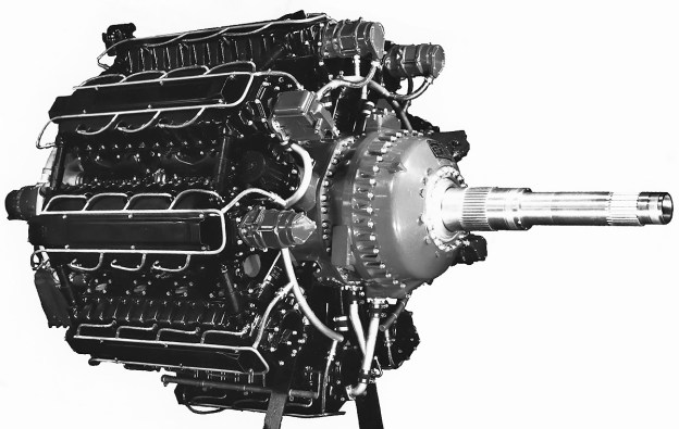
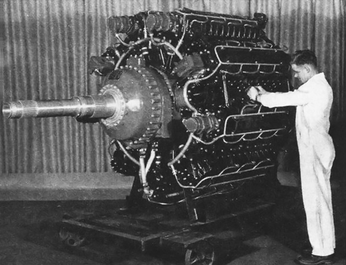
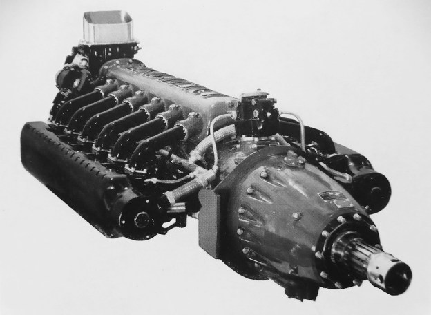
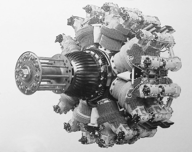
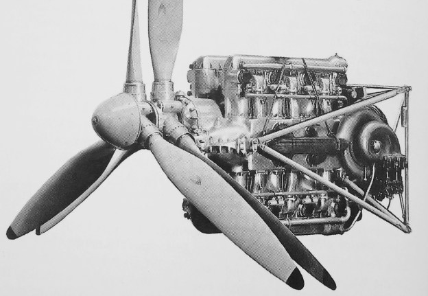
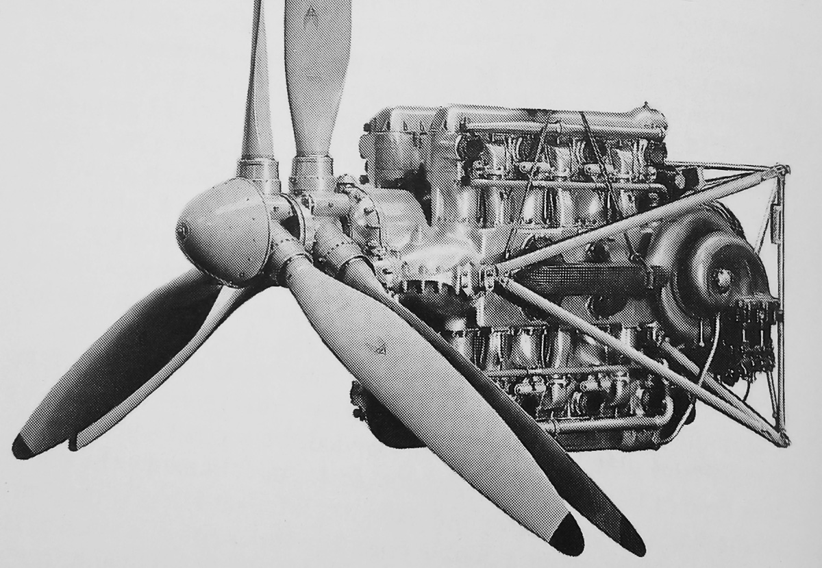
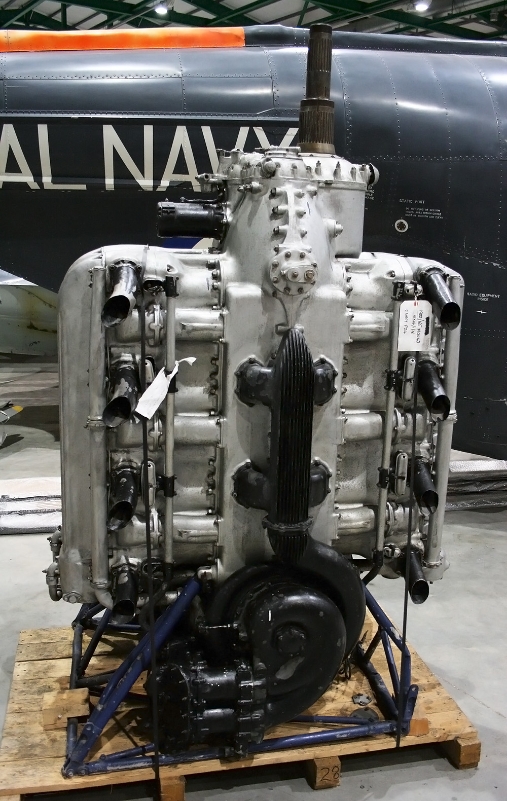
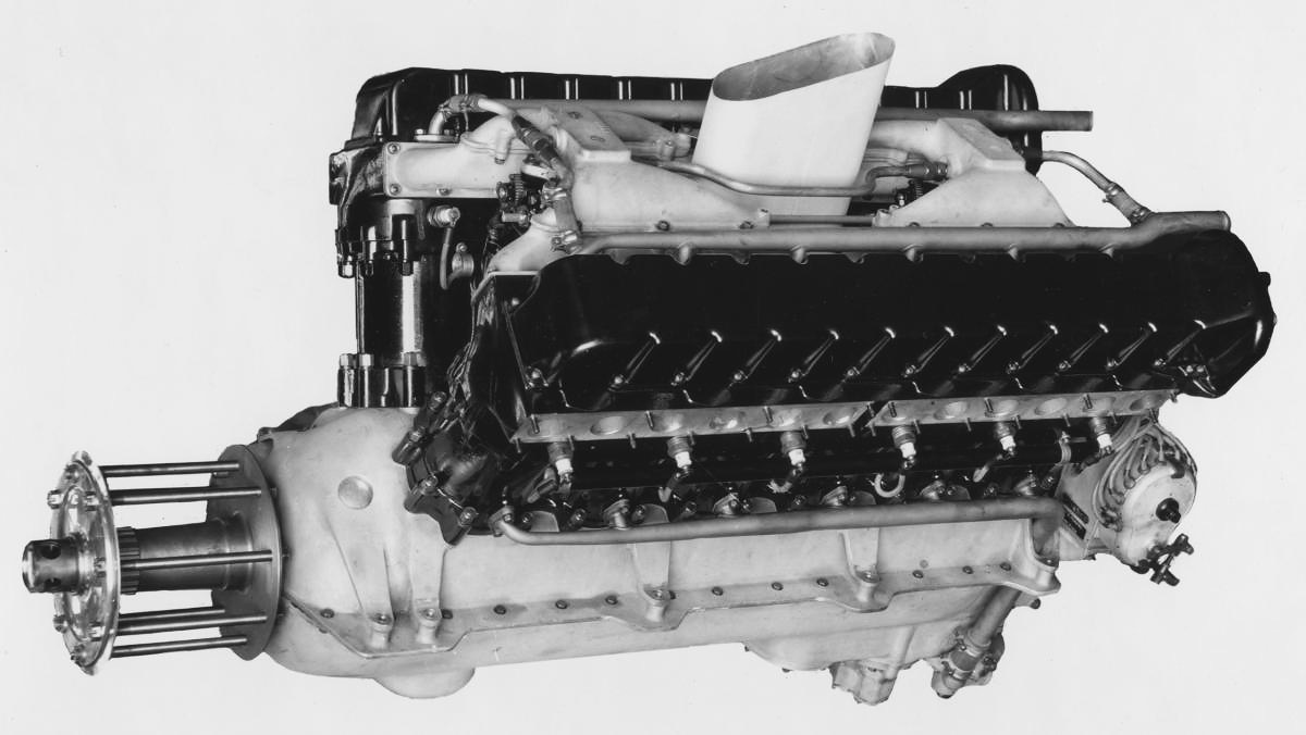
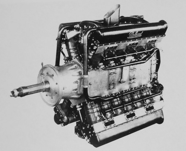
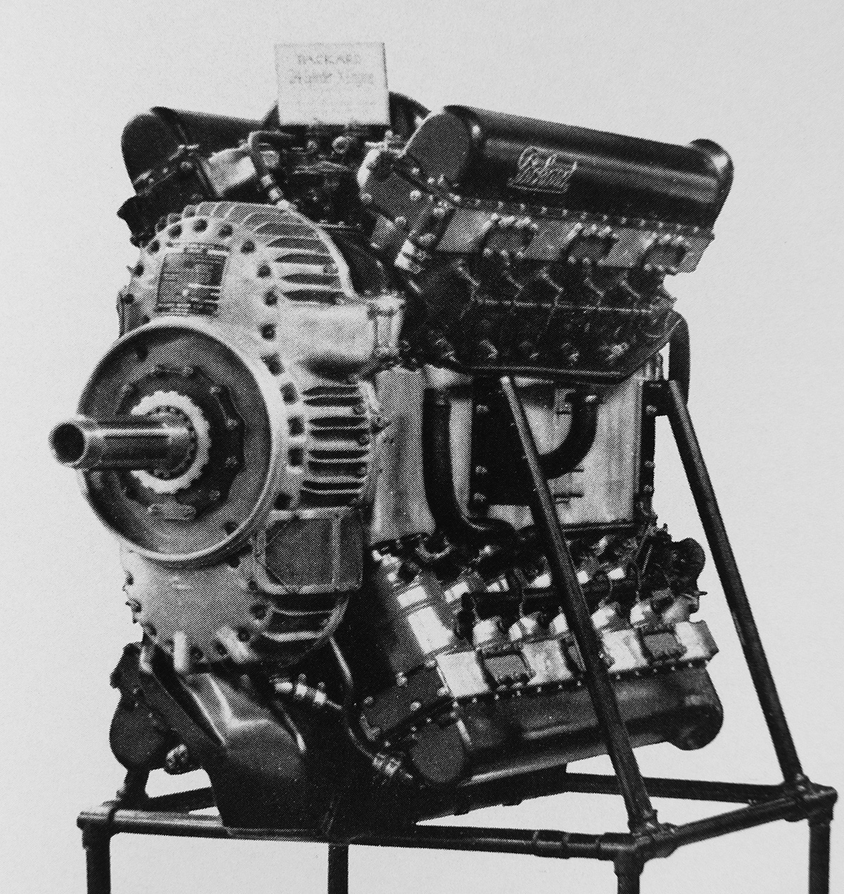
The original Packard X-2775 (1A-2775) was a direct-drive engine installed in the Kirkham-Williams Racer. A housing extended the propeller shaft to better streamline the engine. Two mounting pads were integral with the crankcase, and a third was part of the timing gear cover at the rear of the engine. Note the vertical intake in the center of the upper Vee.

Williams was assembling a group of investors to fund the design and construction of a private racer to participate in the Schneider contest. In addition, the US Navy was willing to indirectly support the efforts of a private entry. With the Navy willing to cover the development of the engine, Packard agreed to build a powerful engine for Williams’ Schneider racer. On 9 February 1927, the US government officially announced that it would not be sending a team to compete in the 1927 Schneider race, held in Venice, Italy. On 24 March 1927, it was announced that a private group of patriotic sportsmen had formed the Mercury Flying Corporation (MFC) to build a racer for the Schneider Trophy contest that would be piloted by Williams. The aircraft was built by the Kirkham Products Corporation and was known as the Kirkham-Williams Racer.

Packard had started the initial design work on the engine shortly after agreeing to its construction, even though a contract had not been issued. Once the Navy had the funds, Contract No. 3224 was issued to cover the engine’s cost. To speed development of the powerful engine, Packard combined components of two proven V-1500 engines to create a new 24-cylinder engine. The new engine was designated the Packard 1A-2775, but it was also commonly referred to by its Navy designation of X-2775.

Packard X-2775 case drive rod crank

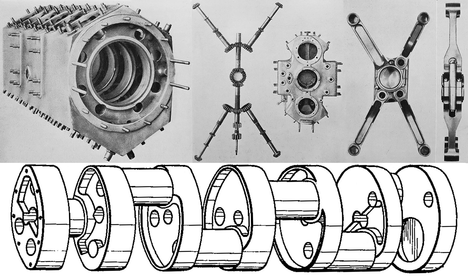
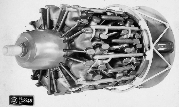
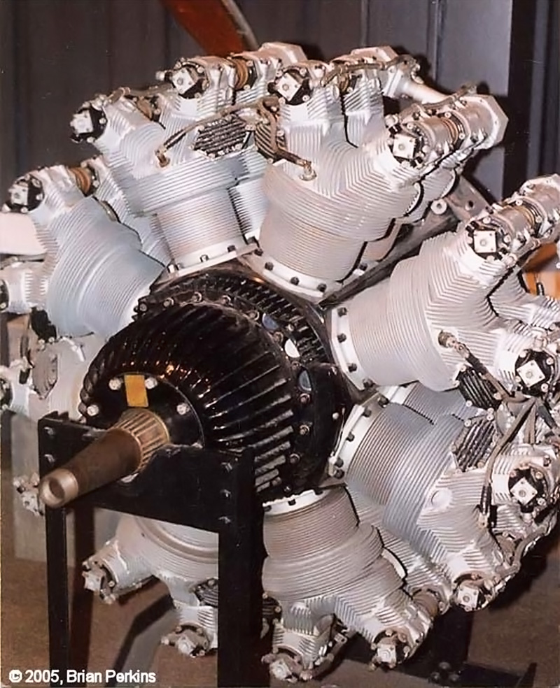
The X-2775’s hexagonal, barrel-type crankcase, timing gear drive and housing, connecting rods, and crankshaft. Note the walls inside of the crankcase, and the crankshaft’s large cheeks that acted as main journals.

The Packard X-2775 was designed by Lionel Melville Woolson. The engine was arranged in an X configuration, with four banks of six cylinders. The upper and lower banks retained the 60-degree bank angle of the V-1500. This left 120-degree bank angles on the sides of the engine. As many V-1500 components were used as possible, including pistons, the basic valve gear, and the induction system. At the front of the X-2775, the propeller shaft ran in an extended housing and was coupled directly to the crankshaft, without any gear reduction. The extended housing allowed for a more streamlined engine installation.

A single-piece, cast aluminum, hexagonal, barrel-type crankcase was used. Two engine mounting pads were provided on each side of the crankcase, and a third pad was incorporated into the side of the timing gear housing, which mounted to the rear of the engine. The crankcase was designed to support landing gear or floats connected to the forwardmost engine mounting pad. Seven integrally cast partitions were provided inside the crankcase. The partitions were hollow at their center and were used to support the crankshaft. The seven single-piece main bearings were made of Babbitt-lined steel rings, shrunk into the crankcase’s partitions, and retained by screws from the outer side of the flanged partition. The partitions had a series of holes around their periphery that allowed for the internal flow of oil as well as enabled assembly of the engine’s connecting rods.

Packard X-2775 manifold and valve spring

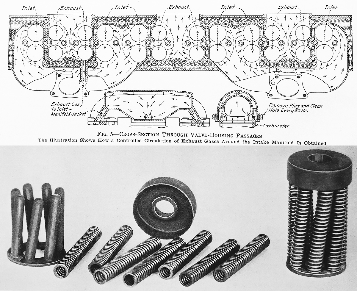
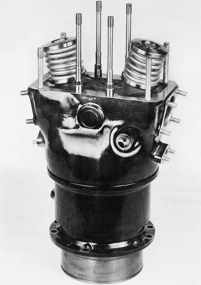
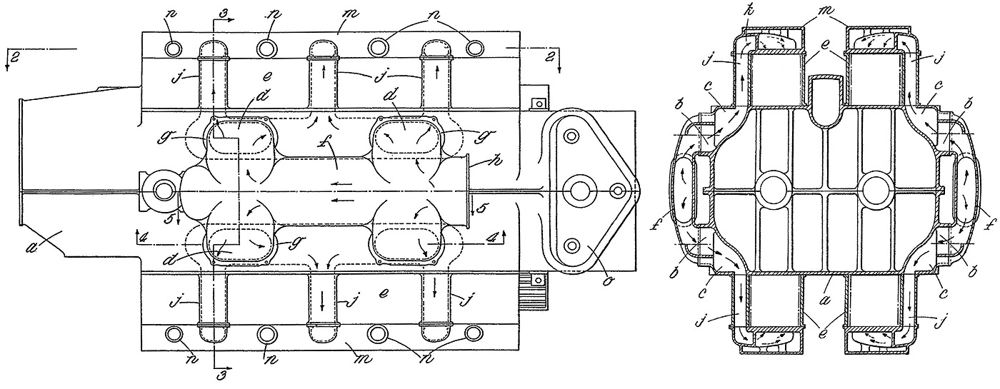
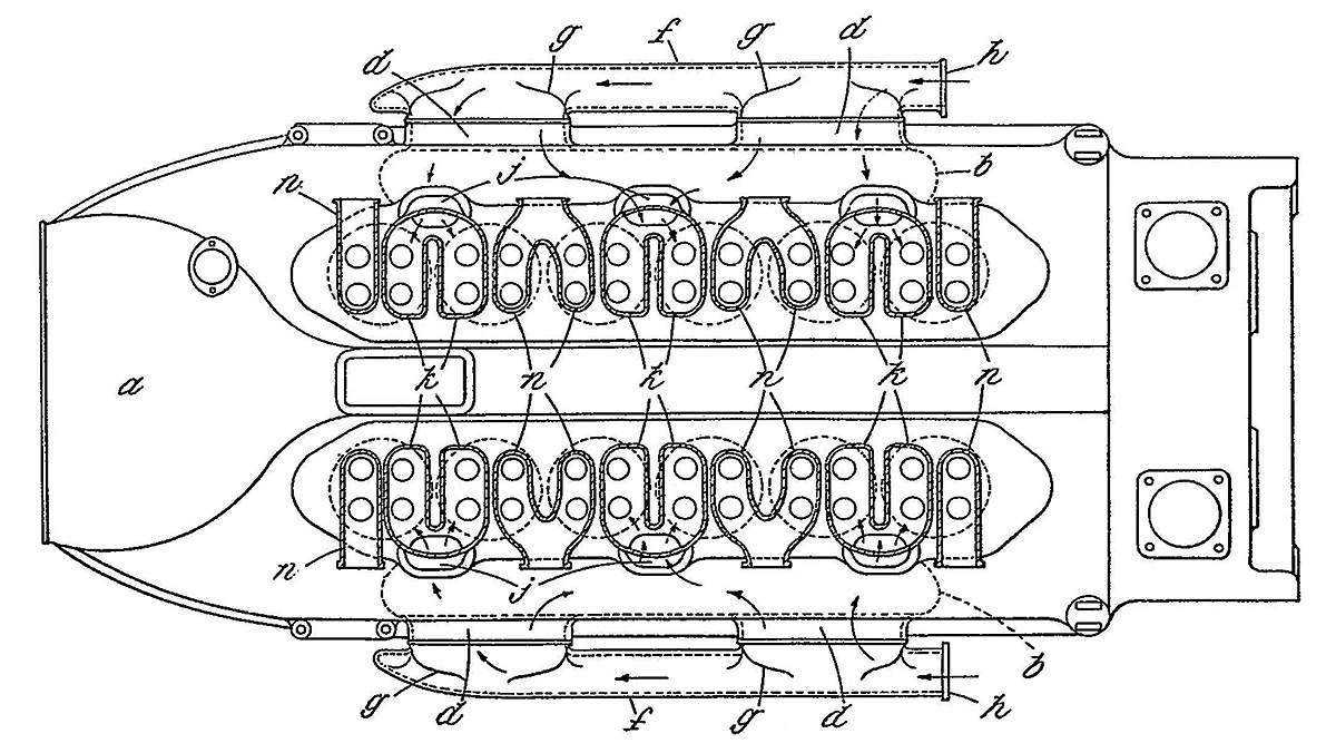
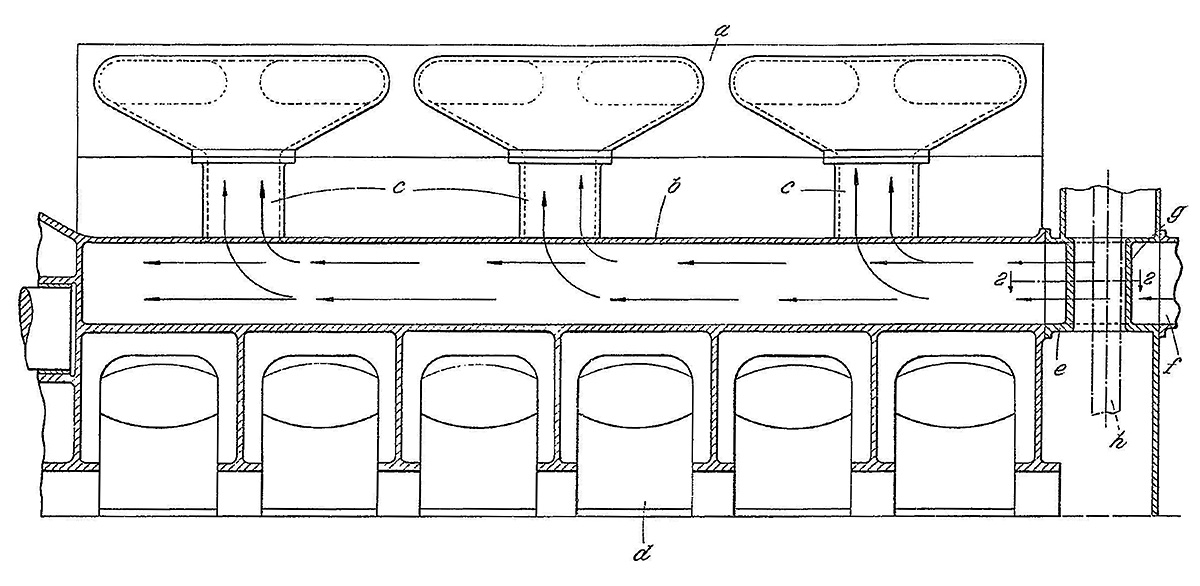
Upper image is the valve port arrangement that was integral with the valve and camshaft housing. The drawing includes the ports to circulate hot exhaust gases around the intake manifold to ensure fuel vaporization. The lower image is the unique valve spring arrangement designed by Lionel Woolson. Helically-twisted guides (left) held the seven small springs (center) to make the complete spring set (right).

The crankshaft was positioned about 1.5 in (38 mm) above the crankcase’s centerline and had six crankpins. The crankshaft’s cheeks acted as main journals. The cheeks were perfectly circular and were 7.75 in (197 mm) in diameter. This design increased the main bearing surface area to support the engine’s power but kept the crankshaft the same overall length as the crankshaft used on the V-1500 engine. A longer crankshaft would result in a longer and heavier engine, as well as necessitating the design and manufacture of new valve housings and camshafts. At 161 lb (73 kg), the crankshaft was around twice the weight of the crankshaft used in the V-1500 engine. The X-2775’s crankshaft was inserted through the center of the crankcase for assembly.

Each connecting rod assembly was made up of a master rod and three articulated rods. The end cap, with its two bosses for the articulating rods, was attached to the master rod by four studs. The articulated rods had forked ends that connected to the blade bosses on the master rod. The forked end of each articulated rod was tapped and secured to the master rod by a threaded rod pin. Once assembled, two bolts passed through the connecting rod assembly to further secure its two halves and also secured the pins of the articulated rods. To accommodate the crankshaft being approximately 1.5 in (38 mm) above center in the crankcase, the lower articulated rods were 1.5 in (38 mm) longer than the other rods. When the engine was viewed from the rear, the master rods were attached to pistons in the upper left cylinder bank.

Packard X-2775 section

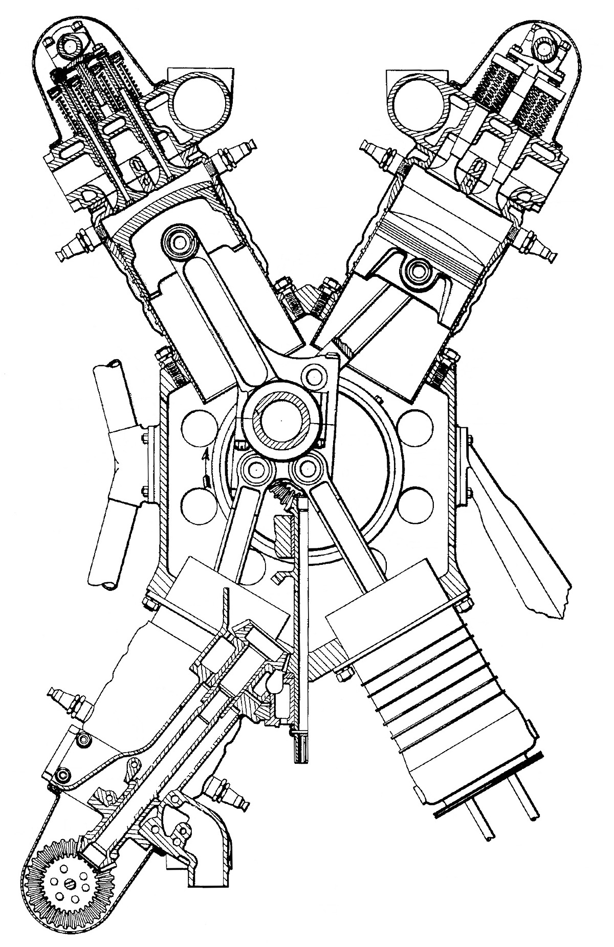
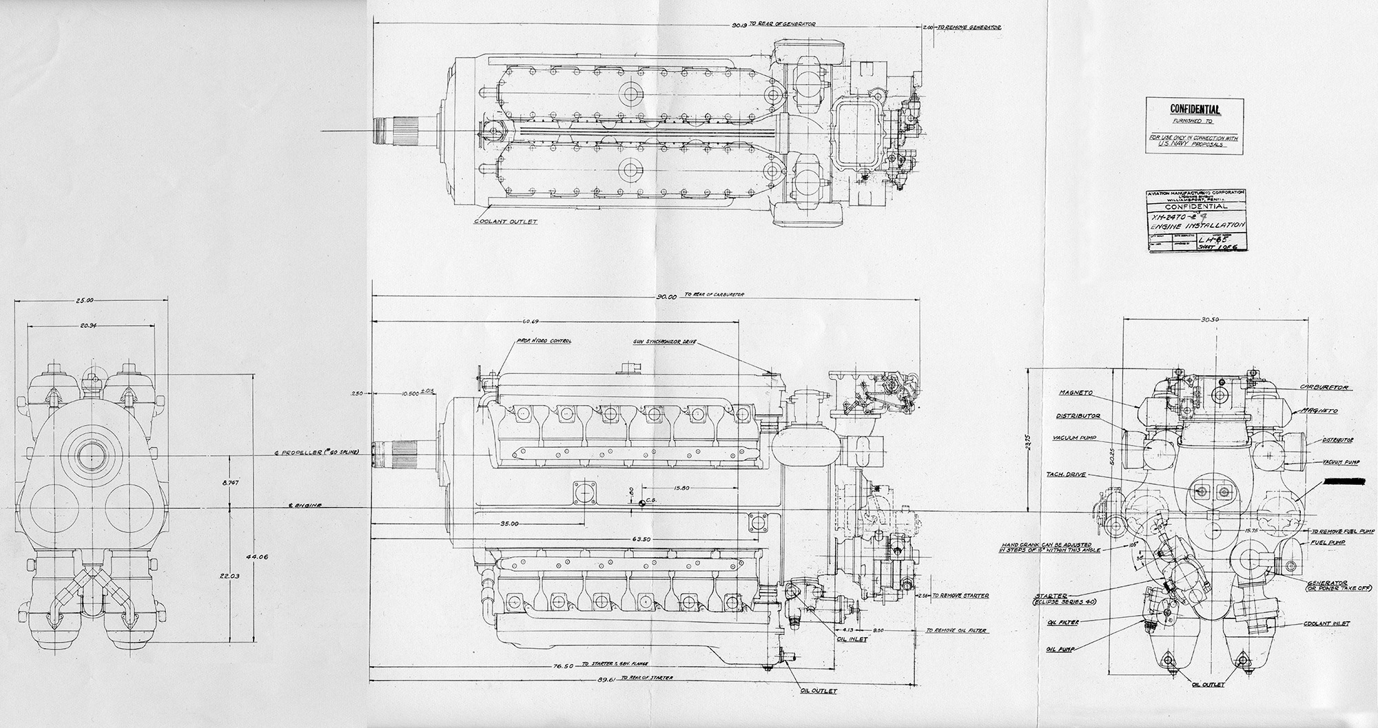
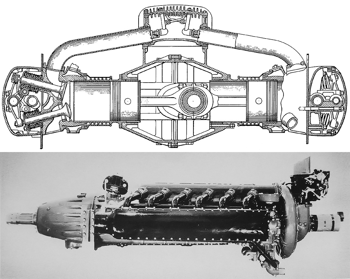
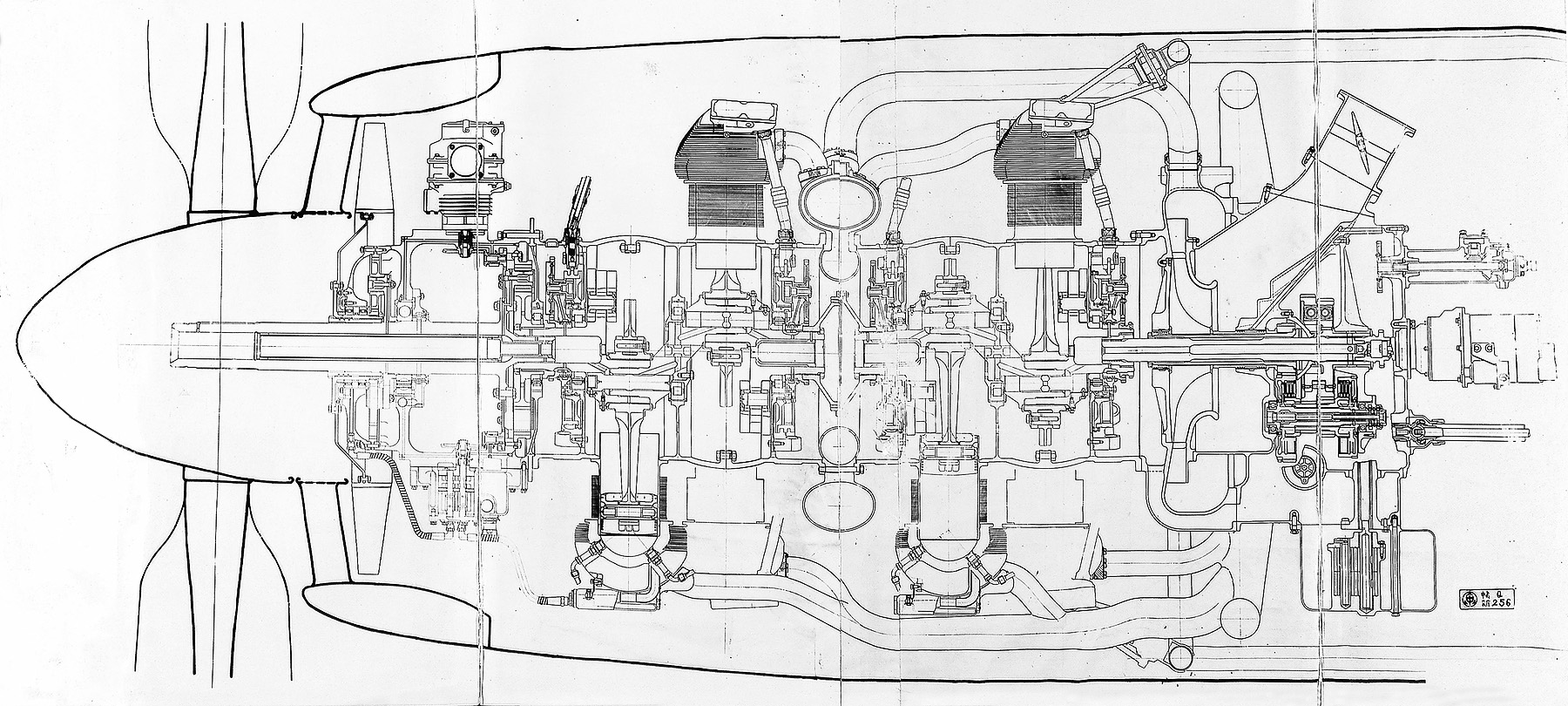
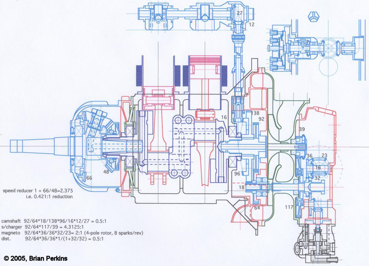
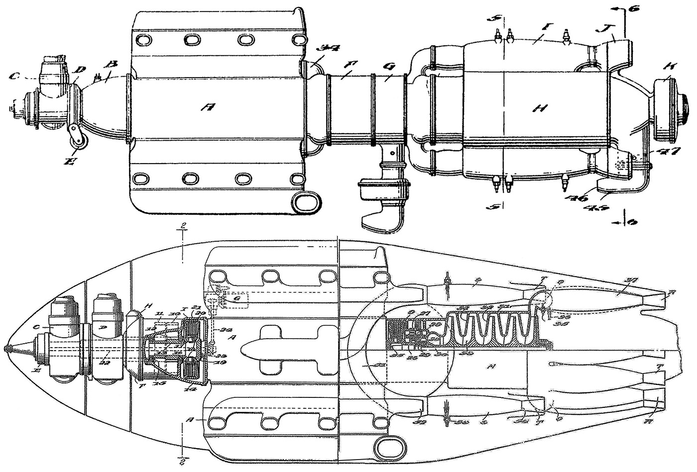
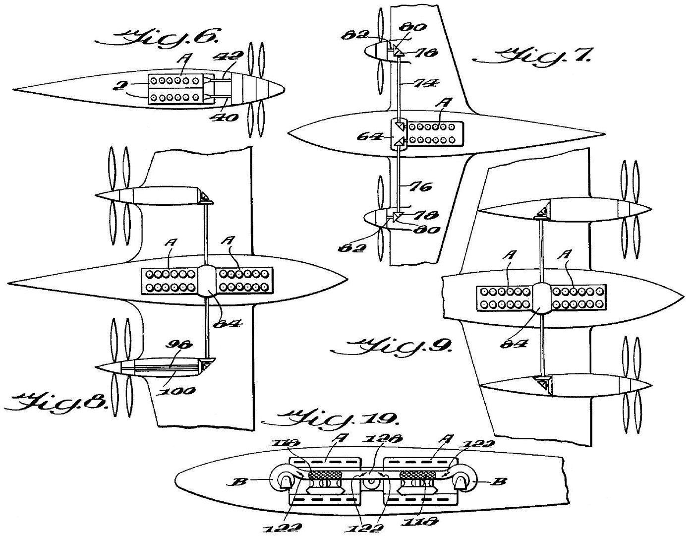
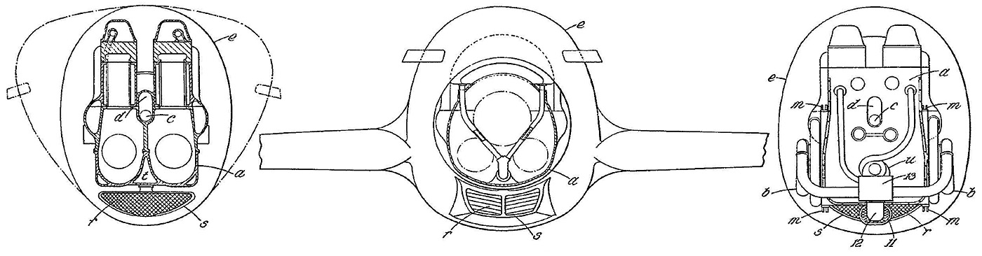
Sectional view of the X-2775 engine. The engine mount is depicted on the left, and the landing gear or float mount is on the right. Note the spark plug position. The revised engine had provisions for four spark plugs—two on each side of the cylinder.

Individual steel cylinders of welded construction with welded-on steel water jackets were mounted to the crankcase via 10 studs. The cylinder’s combustion chamber had machined valve ports and was welded to the top of the cylinder barrel. Five studs protruded above each cylinder’s combustion chamber and were used to secure the cast aluminum valve and camshaft housing. Each bank of six cylinders had a single valve and camshaft housing.

Each cylinder had two intake and two exhaust valves. The valves were arranged so that one intake and one exhaust valve were on the Vee side of the cylinder, and the pairing was duplicated on the other side of the cylinder. The valve and camshaft housing collected the exhaust gases from two adjacent cylinders and expelled it out one of three exhaust ports. The valve and camshaft housing also had an integral intake manifold that fed three cylinders. The valves for each cylinder bank were actuated by a single overhead camshaft driven by an inclined shaft at the rear of the engine. The two inclined shafts for each Vee engine section were driven by a vertical shaft geared to the crankshaft. The lower vertical shaft was extended to drive one fuel, one water, and four oil pumps. The shafts were enclosed in the timing gear housing that mounted to the back of the engine. The valve covers of the lower cylinders also formed sumps for engine oil collection. Oil was circulated through various passageways in addition to the hollow crankshaft and hollow camshaft. The exhaust valve had a hollow stem for oil cooling.

The valve springs were designed by Woolson and were a unique design. Rather than the valve stem passing through the center of one or two valve springs, a set of seven smaller springs encircled the valve stem. Each of the seven springs was mounted on a guide, and the set was contained in a special retainer. The seven spring guides were given a slight helical twist. The special valve spring set distributed the spring load evenly around the valve stem, reduced the likelihood of a valve failure due to a spring breaking, prevented valve springs from setting, and also rotated the valve during engine operation. The valve rotation was one revolution for about every 40 revolutions of the crankshaft.

Packard X-2775 front and back

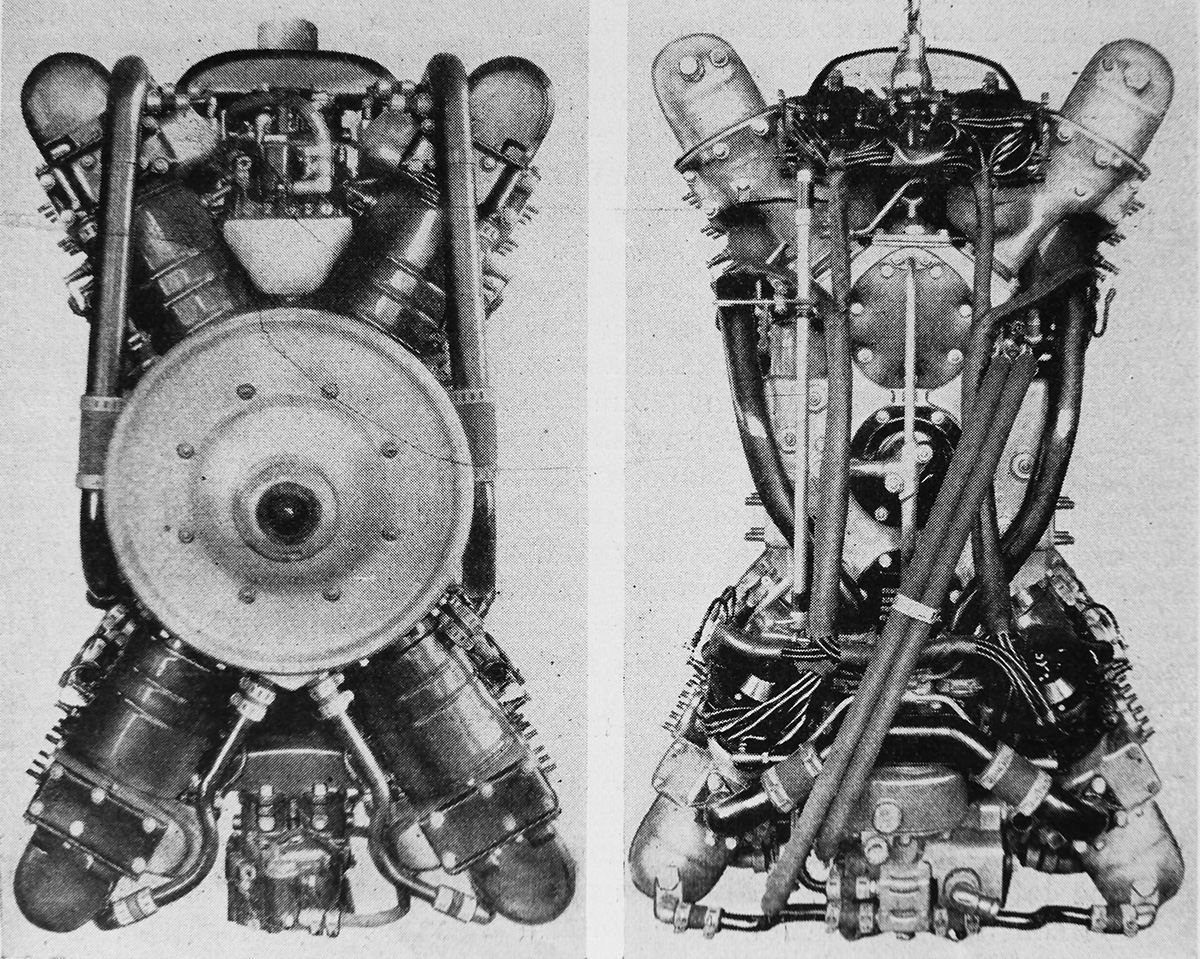
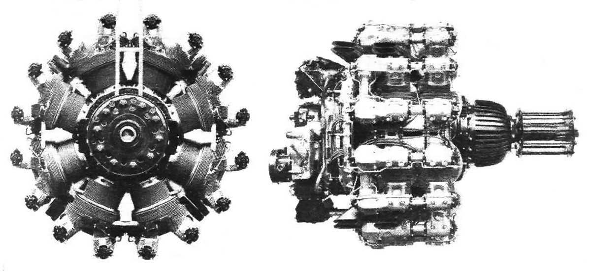
Front and rear views of the original X-2775 illustrate that the engine was narrow but rather tall. The ring around the propeller shaft was a fixed attachment point for the engine cowling.

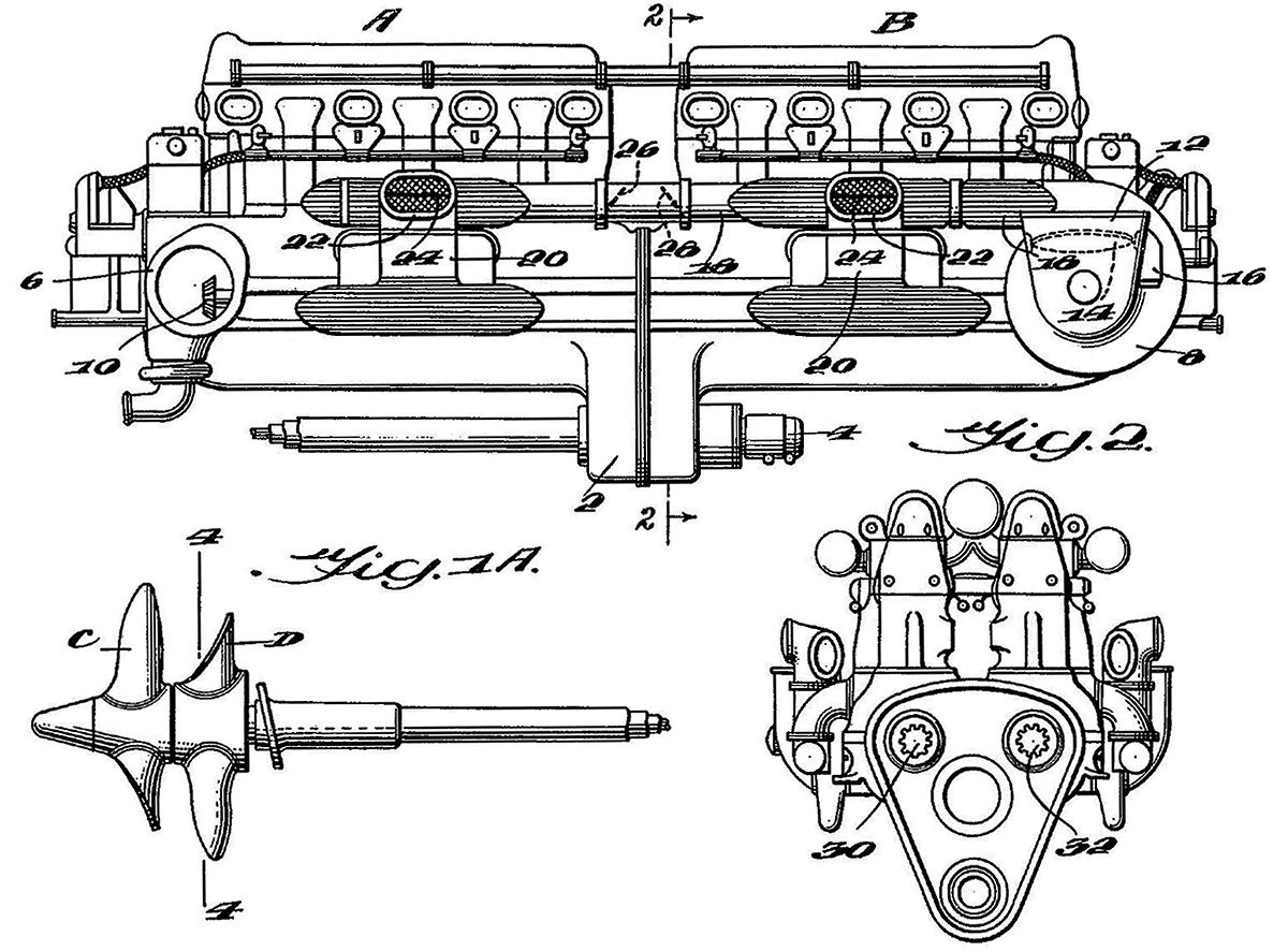
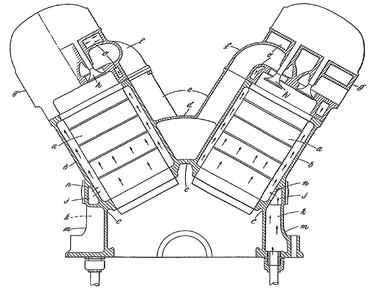
Each cylinder’s combustion chamber had a flat roof with a spark plug on each side of the cylinder. The spark plugs were fired by a battery-powered ignition system via four distributors driven at the rear of the engine. Two distributors were positioned behind each 60-degree cylinder bank Vee. In each cylinder, one spark plug was fired by an upper distributor, and one spark plug was fired by a lower distributor. Separate induction systems were positioned in the upper and lower cylinder Vees. Each system consisted of a central inlet that branched into a forward and rear section. Each section had a carburetor and fed six cylinders. This gave the engine a total of four carburetors—two in each upper and lower vee. Control rods linked the carburetors to the distributors so that ignition timing was altered with throttle position. A port in the valve and camshaft housing fed exhaust gases through a jacket surrounding the manifold to which the carburetor mounted. The exhaust gases heated the intake manifold to better vaporize the incoming fuel charge.

Packard’s V-1500 engine had a 5.375 in (137 mm) bore and a 5.5 in (140 mm) stroke. The X-2775 had the same 5.375 in (137 mm) bore, but the stroke was shortened to 5.0 in (127 mm). However, the three articulated connecting rods had a slightly longer stroke of 5.125 in (130 mm). Each of the six cylinders served by a master rod had a displacement of 113.5 cu in (1.86 L), and each of the 18 cylinders served by an articulated rod had a displacement of 116.3 cu in (1.91 L). The total displacement for the engine was 2,774 cu in (45.5 L). The X-2775 produced a maximum of 1,250 hp (932 kW) at 2,780 rpm and was rated for 1,200 hp (895 kW) at 2,600 rpm. At 2,000 rpm, the engine had an output of 800 hp (597 kW). The X-2775 was 77.5 in (1.97 m) long, 28.3 in wide (.72 m), and 45.2 in (1.15 m) tall. The weight of the initial X-2775 was 1,402 lb (636 kg).

Packard X-2775 no 2 supercharged

The second X-2775 incorporated a Roots-type supercharger driven from the propeller shaft. Difficulty was encountered with fuel metering since the carburetors were positioned on the pressure side of the supercharger. The supercharged engine was never installed in an aircraft.

The X-2775 engine was completed in June 1927 and subsequently passed an acceptance test, which involved the engine running continuously at full throttle for one hour. Williams was involved with testing the X-2775 at Packard to gain experience with its operation. The engine was then shipped out for installation in the Kirkham-Williams Racer, which was finished in late July. The racer and the X-2775 made their first flight on 25 August. Despite achieving speeds around 270 mph (435 km/h), the racer had issues that could not be resolved in time for the Schneider Trophy contest, scheduled to start on 23 September. The Kirkham-Williams Racer was subsequently converted to a land plane, and Williams flew the aircraft over a 3 km (1.9 mi) course unofficially timed at 322.42 mph (518.88 km/h) on 6 November 1927. However, that speed was with the wind, and Williams later stated that the true speed was around 287 mph (462 km/h). Higher speeds had been anticipated. The aircraft was then shipped to the Navy Aircraft Factory (NAF) at Philadelphia, Pennsylvania.

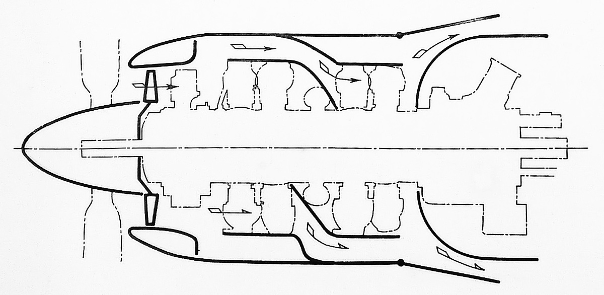
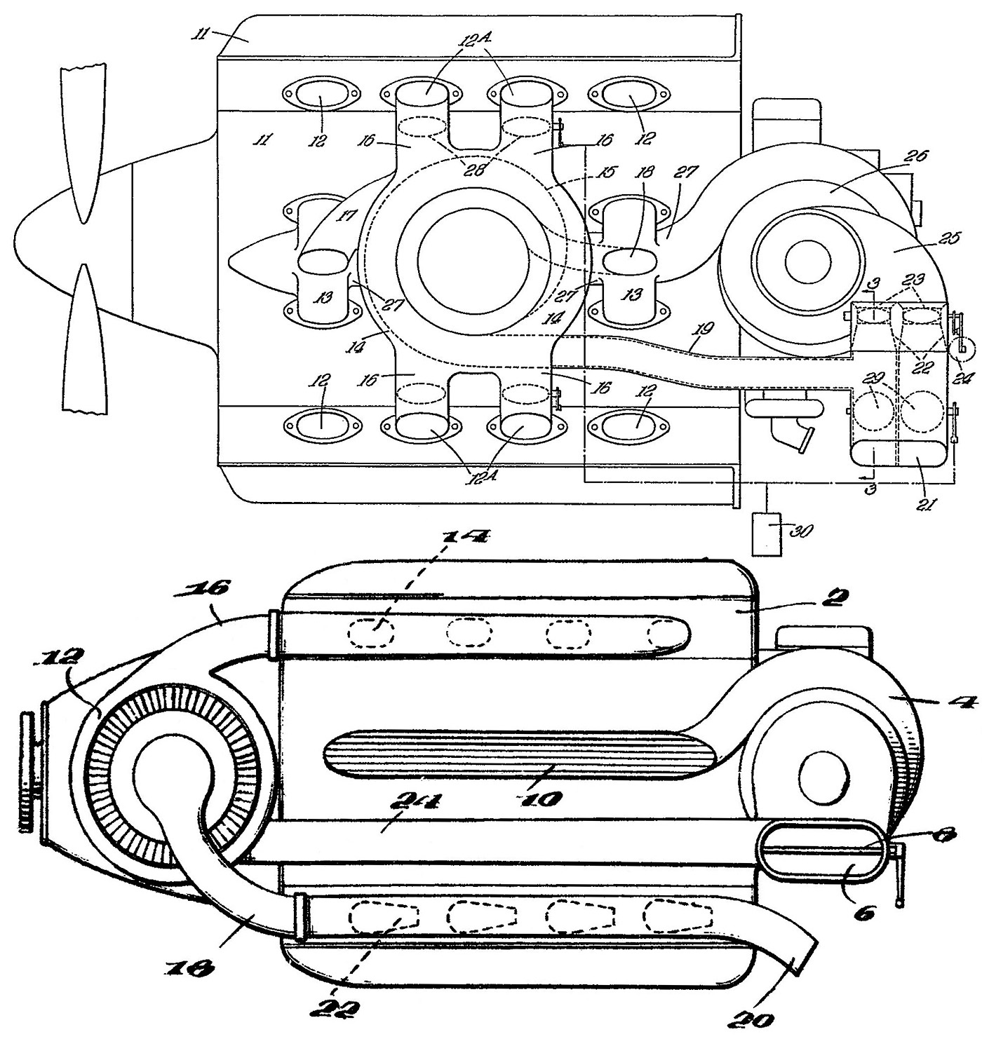
Around late June 1927, rumors indicated that the Schneider competition would be faster than the Kirkham-Williams Racer. As a result, the Navy added a second X-2775 engine to its existing contract with Packard. The second engine incorporated a supercharger for increased power output. In the span of 10 weeks, Packard had designed, constructed, and tested the new engine. The second X-2775 engine was, again, direct drive. However, the propeller shaft also drove a Roots-style supercharger with three rotors (impellers). A central rotor was coaxial with the propeller shaft, and it interacted with an upper and lower rotor that supplied forced induction to the respective upper and lower cylinder banks. For the upper Vee, air was brought in the right side of the supercharger housing and exited the left side, flowing into a manifold routed between the upper cylinder banks. For the lower Vee, the flow was reversed—entering the left side of the supercharger and exiting the right. The supercharged X-2775 weighed around 1,635 lb (742 kg).

Because of the very tight development schedule, the rotors were given generous clearances. This reduced the amount of boost the supercharger generated to only 3.78 psi (.26 bar), which increased the X-2775’s output to 1,300 hp (696 kW) at 2,700 rpm. Tighter rotor tolerances would yield 4.72 psi (.33 bar) of boost and 1,500 hp (1,119 kW) at 2,700 rpm. However, it is not known if improved rotors were ever built. Although completed around August 1927, the supercharged engine was never installed in the Kirkham-Williams Racer.

Packard X-2775 NASM left

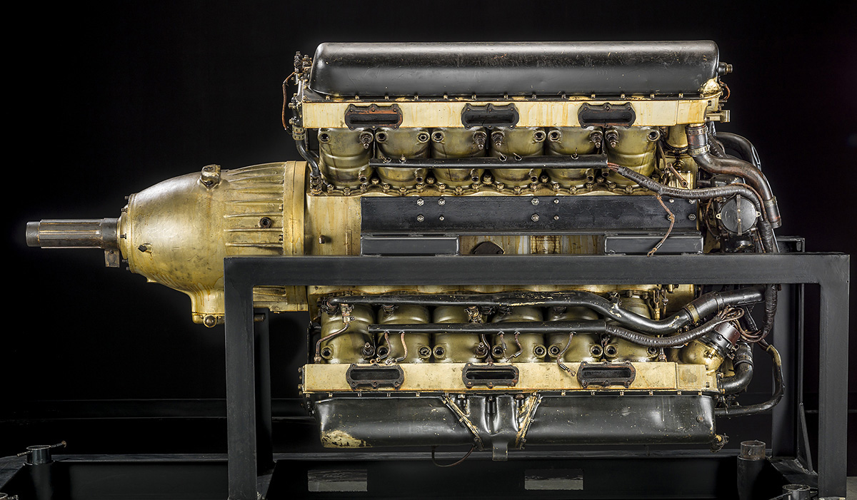
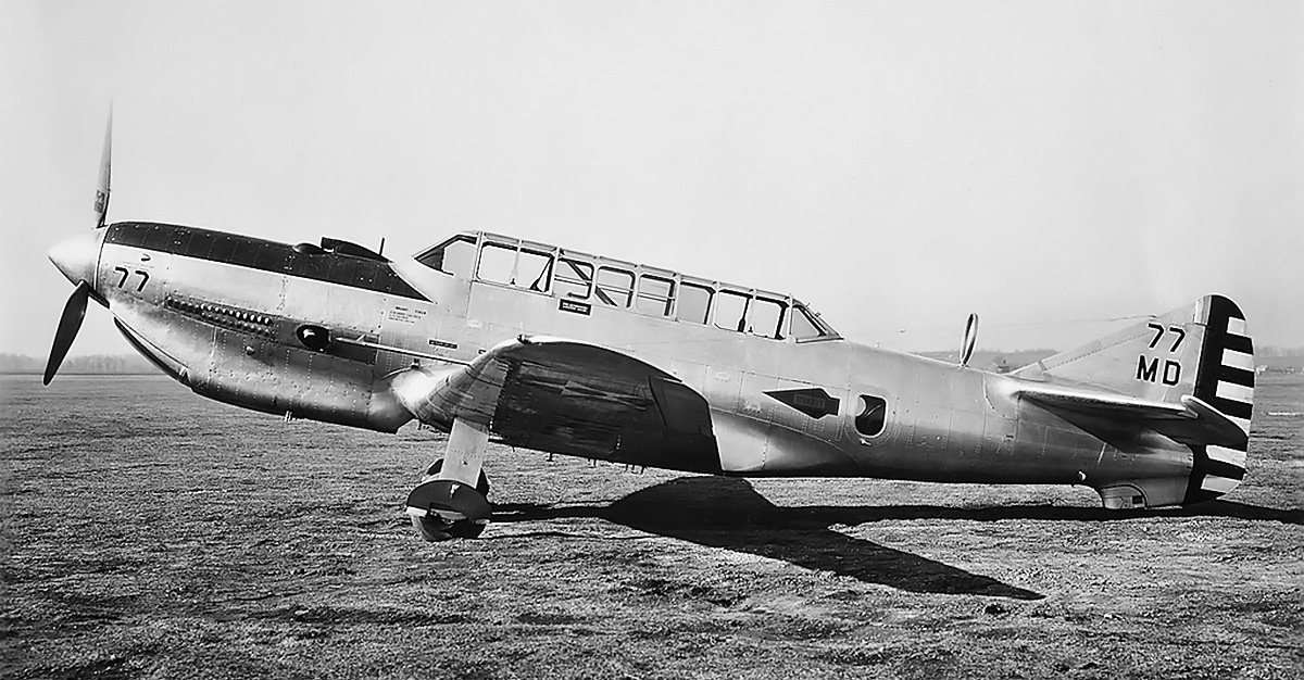
The first X-2775 engine was reworked with a propeller gear reduction, new cylinders, new valve housings, and a new induction system. This engine was installed in the Williams Mercury Racer. (NASM image)

The Navy felt that adding a propeller gear reduction to the engine would be more beneficial than the supercharger. To this end, the unsupercharged engine was removed from the Kirkham-Williams Racer as the aircraft was disassembled in the NAF around early 1928. The engine was returned to Packard for modifications. A new aircraft, the Williams Mercury Racer, was to be built, and the first X-2775 engine with the new gear reduction and other modifications would power the machine.

A planetary (epicyclic) gear reduction was built by the Allison Engineering Company in Indianapolis, Indiana. This gear reduction mounted to the front of the engine and turned the propeller at .677 crankshaft speed. Other modifications to the X-2775 included using cylinders and valve housings from an inverted 3A-1500 (the latest V-1500) engine and revising the induction and ignition systems.

The new cylinders increased the engine’s compression (most likely to 7.0 to 1) and had provisions for two spark plugs on both sides of the cylinder. Still, only two spark plugs were used, with one on each side of the cylinder. The new induction was a ram-air system with inlets right behind the propeller. The air flowed into a manifold located deep in the cylinder bank’s Vee. Two groups of two carburetors were mounted to the manifold. Each carburetor distributed the air/fuel mixture to a short manifold that fed three cylinders. The revised ignition system used two magnetos and did away with battery power. The magnetos were mounted to the rear of the engine and driven from the main timing gear. The improved X-2775 was occasionally referred to as the 2A-2775, but it mostly retained the same 1A-2775 Packard designation of its original configuration. The geared X-2775 produced 1,300 hp (969 kW) at 2,700 rpm and weighed around 1,513 lb (686 kg). The gear reduction added about 3 in (76 mm) to the engine, resulting in an overall length of 80.5 in (2.04 m). The width was unchanged at 28.3 in (.72 m), but the revised induction system reduced the engine height slightly to 43.25 in (1.10 m).

Packard X-2775 NASM front

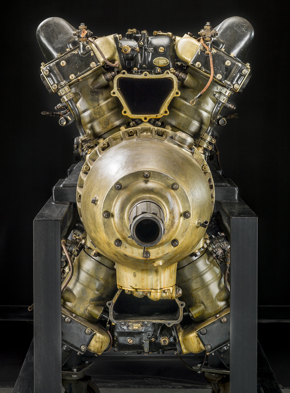
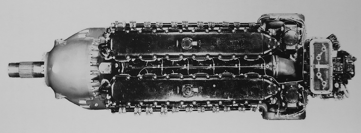
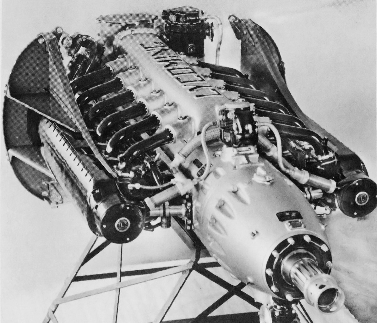
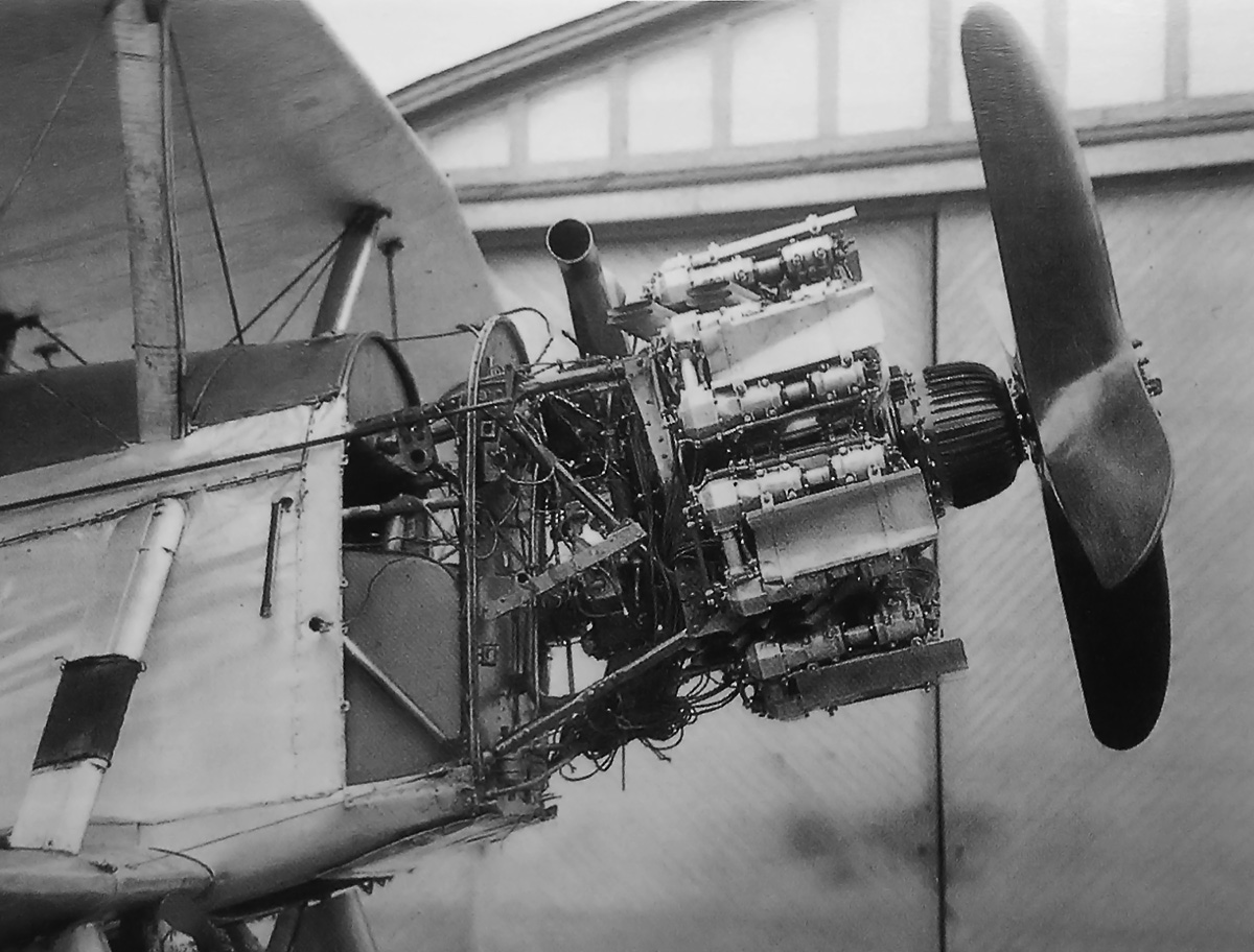
The revised X-2775 took advantage of ram-air induction. Intakes directly behind the Williams Mercury Racer’s spinner fed air into manifolds at the base of the cylinder Vees. Note the spark plugs on both sides of the cylinders. (NASM image)

The updated X-2775 engine was installed in the Williams Mercury Racer in July 1929. In early August, flight testing was attempted on Chesapeake Bay near the Naval Academy in Annapolis, Maryland. While the aircraft was recorded at 106 mph (171 km/h) on the water, it could not lift off. The Williams Mercury Racer was known to be overweight, and there were questions about its float design. The trouble with the racer caused it to be withdrawn from the Schneider Trophy contest, scheduled to start on 6 September in Calshot, England. Later, it was found that the Williams Mercury Racer was some 880 lb (399 kg), or 21%, overweight. Some additional work was done on the aircraft, but no further attempts at flight were made.

Of the original X-2775, Woolson stated that the engine ran for some 30 hours, and at no time was mechanical trouble experienced or any adjustments made. Williams made some comments about the X-2775 losing power, but he otherwise seemed satisfied with the engine and did not report any specific issues. Assistant Secretary of the Navy for Aeronautics David S. Ingalls did not make any negative comments about the engine, but he said Commander Ralph Downs Weyerbacher of the NAF felt that the engine was not satisfactory. However, the basis for Weyerbacher’s opinion has not been found.

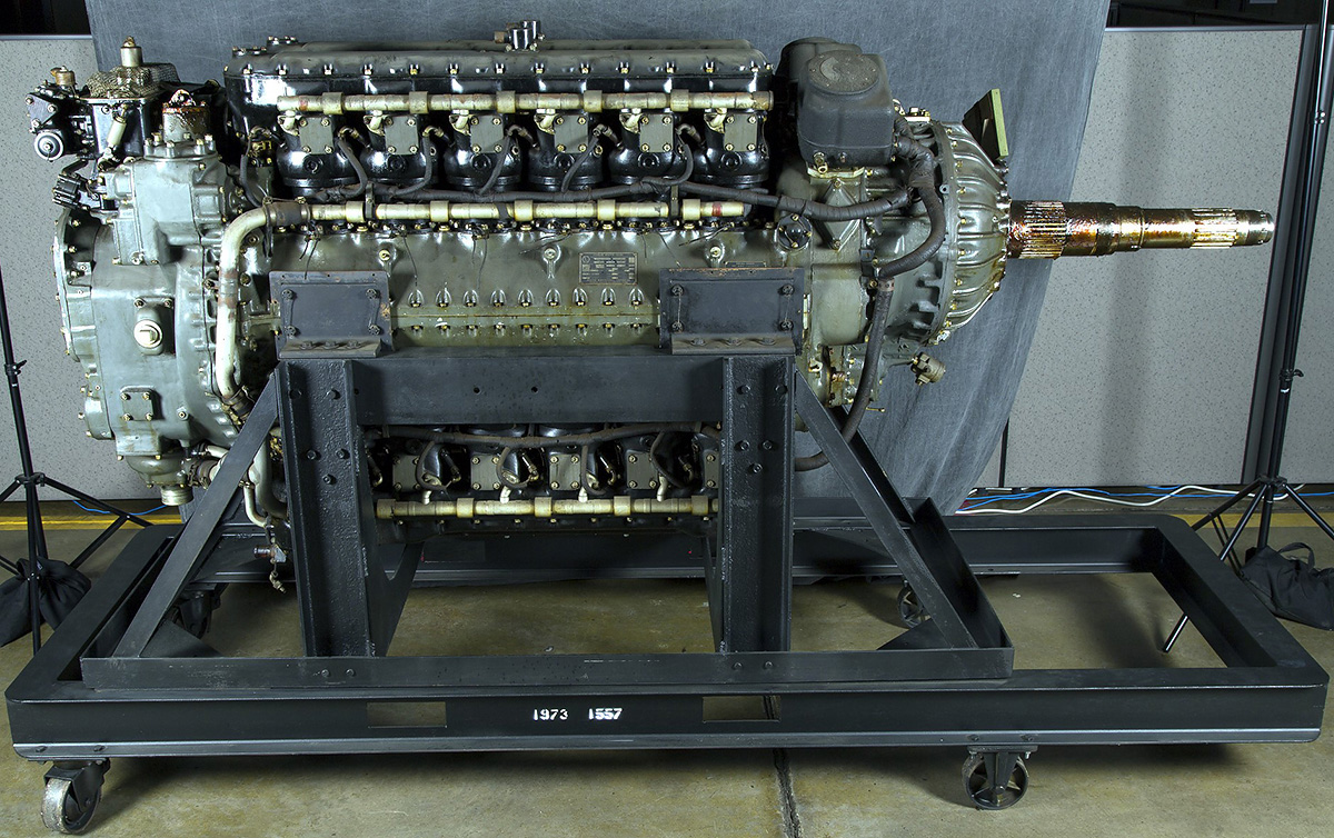
There were essentially no X-2775 test engines. Only two engines were made, and the second engine was never installed in any aircraft. The very first X-2775 built was installed in the Kirkham-Williams Racer, and the majority of the issues encounter seemed to come from the aircraft, and not the engine. This scenario repeated itself two years later with the Williams Mercury Racer. The X-2775 did not have any issues propelling the updated racer at over 100 mph (161 km/h) on the surface of the water, but it was the aircraft that was overweight and unable to take flight. If the engine were significantly flawed, it would not have survived its time in the Kirkham-Williams Racer, have been subsequently modified, and then installed in the Williams Mercury Racer. This same engine, Serial No. 1, was preserved and is in storage at the Smithsonian National Air and Space Museum.

Packard offered to build additional X-2775 engines for anyone willing to spend $35,000, but no orders were placed. In the late 1930s, Packard investigated building an updated X-2775 as the 2A-2775. The 2A-2775 was listed as a supercharged engine that produced 1,900 hp (1,417 kW) at 2,800 rpm and weighed 1,722 lb (781 kg). Some sources indicate the engine was built, although no pictures or test data have been found.

Packard X-2775 NASM top

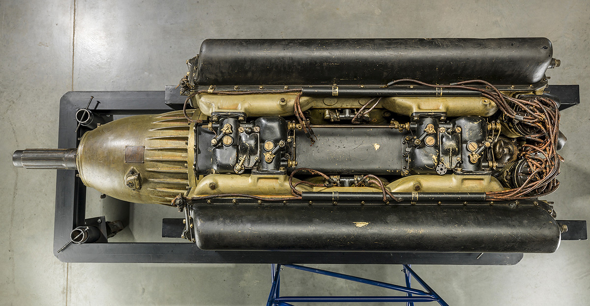
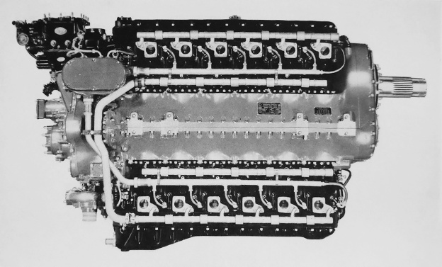
Top view of the X-2775 illustrates the two sets of two carburetors, with each carburetor attached to a manifold for three cylinders. The intake manifold can be seen running under the carburetors. (NASM image)

Sources:
– “The Packard X 24-Cylinder 1500-Hp. Water-Cooled Aircraft Engine” by L. M. Woolson S.A.E. Transactions 1928 Part II. (1928)
– “Internal Combustion Engine” US patent 1,889,583 by Lionel M, Woolson (granted 29 November 1932)
– “Valve-Operating Mechanism” US patent 1,695,726 by Lionel M, Woolson (granted 18 December 1928)
– “Lieut. Alford J. Williams, Jr.—Fast Pursuit and Bombing Planes” Hearings Before a Subcommittee of the Committee on Naval Affairs, United States Senate, Seventy-first Congress, second session, on S. Res. 235 (8, 9, and 10 April 1930)
– “Packard “X” Type Aircraft Engine is Largest in World” Automotive Industries (8 October 1927)
Master Motor Builders by Robert J. Neal (2000)
Packards at Speed by Robert J. Neal (1995)
Jane’s All the World’s Aircraft 1929 by C. G. Gray (1929)
https://airandspace.si.edu/collection-objects/packard-1a-2775-x-24-engine

Daimler-Benz DB 604

Daimler-Benz DB 604 X-24 Aircraft Engine

By William Pearce

In July 1939, the RLM (Reichsluftfahrtministerium, or Germany Air Ministry) issued specifications for a new medium bomber capable of high-speeds. Originally known as Kampfflugzeug B (Warplane B), the aircraft proposal was eventually renamed Bomber B. The Bomber B specification requested an aircraft that could carry a 2,000 kg (4,410 lb) bomb load 3,600 km (2,237 mi) and have a top speed of 600 km/h (373 mph). To power the Bomber B aircraft, the RLM requested engine designs from BMW, Junkers, and Daimler-Benz. The respective companies responded with the BMW 802, the Junkers Jumo 222, and the Daimler-Benz DB 604.

Daimler-Benz DB 604

The Daimler-Benz DB 604 was designed in 1939 to power the next generation of German fast bombers under the Bomber B program. However, the engine was not selected for production.

The DB 604 was an all-new, liquid-cooled, 24-cylinder engine. Four banks of six cylinders were arranged in an “X” configuration with each cylinder bank spaced at 90 degrees. The X-24 engine consisted of a two-piece aluminum alloy crankcase split horizontally at its center. The engine’s single crankshaft had six crankpins that were spaced at 0 degrees, 120 degrees, 240 degrees, 240 degrees, 120 degrees, and 0 degrees. This arrangement resulted in cylinders firing evenly at every 30 degrees of crankshaft rotation. Attached to each crankpin was a master connecting rod that accommodated three articulated connecting rods. A gear reduction at the front of the engine turned the propeller at .334 crankshaft speed. A supercharger mounted to the rear of the engine had an upper and a lower outlet. Each outlet was connected to two intake manifolds that ran along the inner Vee side of the cylinder banks.

The DB 604’s fuel system was located in the upper and lower Vees of the engine and consisted of fuel injection pumps and individual fuel injectors for each cylinder. Each cylinder had two intake and two exhaust valves, all of which were actuated by a single overhead camshaft. The camshaft for each cylinder bank was driven via a vertical shaft from the rear of the engine. The exhaust ports were positioned in the left and right Vees, as were the two spark plugs per cylinder. The spark plugs were fired by two magnetos positioned in the left and right Vees and mounted to the propeller gear reduction housing.

Daimler-Benz DB 604 side

The DB 604 was a rather compact design. A magneto can be seen at the front of the engine between the exhaust ports of the upper and lower cylinder banks. Note the supercharger at the rear of the engine. (Evžen Všetečka image via www.aircraftengine.cz)

The DB 604 had a 5.31 in (135 mm) bore and stroke and displaced 2,830 cu in (46.4 L). The engine had a 7.0 to 1 compression ratio and weighed 2,381 lb (1,080 kg). The DB 604 prototype was first run in late 1939. The first engine produced 2,313 hp (1,725 kW) at 3,200 rpm. This engine may have had a single-speed supercharger. The DB 604 A and DB 604 B engines were produced quickly after the first prototype. These engines had a two-stage supercharger that provided 6.17 psi (.43 bar) of boost. The difference between A and B versions was the rotation of the engine’s crankshaft. The DB 604 A/B had a maximum output at 3,200 rpm of 2,660 hp (1,984 kW) at sea level and 2,410 hp (1,797 kW) at 20,600 ft (6,279 m). The engine’s maximum continuous output was 2,270 hp (1,693 kW) at sea level and 2,120 hp (1,581 kW) at 21,000 ft (6,401 m), both figures at 3,000 rpm. Maximum cruise power was at 2,800 rpm, with the engine producing 1,830 hp (1,365 kW) at sea level and 1,860 hp (1,387 kW) at 20,000 ft (6,096 m). The DB 604 was flight tested in a Junkers Ju 52 trimotor transport, but it is not clear which version of the engine was tested. At least five DB 604 engines were made.

The Bomber B proposals that moved forward as prototypes were the Dornier Do 317, Focke-Wulf Fw 191, and Junkers Ju 288. Despite the DB 604 showing some promise, the RLM chose the Jumo 222, and work on the DB 604 was stopped in September 1942. No records have been found that detail the DB 604’s reliability, and many other X-24 aircraft engine designs were prone to failure. The sole surviving Daimler-Benz DB 604 engine is on display at the Flugausstellung L.+ P. Junior museum in Hermeskeil, Germany.

Daimler-Benz DB 604 right

Some of the fuel injection equipment is just visible in the engine’s upper Vee. The sole surviving DB 604 engine is on display at the Flugausstellung L.+ P. Junior museum in Hermeskeil, Germany. (Evžen Všetečka image via www.aircraftengine.cz)

Ultimately, the Ju 288 was selected as the winner of the Bomber B program. Delays with the 2,500 hp (1,964 kW) Jumo 222 led to it being substituted with the 2,700 hp (2,013 kW) Daimler-Benz DB 606, and that engine was later replaced by the 2,950 hp (2,200 kW) DB 610. The DB 606 consisted of two DB 601 inverted V-12 engines coupled side-by-side, while the DB 610 was the same arrangement but with two DB 605 engines. The Ju 288 aircraft and the Jumo 222 engine never entered large-scale production.

An enlarged version of the DB 604 was contemplated, with the engine’s bore increased .2 in (5 mm) to 5.51 in (140 mm). This gave the engine a displacement of 3,044 cu in (49.9 L). The larger 90-degree, X-24 engine was very similar to the DB 604 but incorporated a three-speed, three-stage supercharger. The engine was forecasted to produce 3,450 hp (2,575 kW) at 36,089 ft (11,000 m). Development of the larger engine did not progress beyond the initial design phase.

Daimler-Benz DB 604 left


Despite a number of X-24 aircraft engines being made, none truly were produced beyond the prototype phase, and the DB 604 was no exception. Note that the two intake manifolds between the upper (and lower) cylinder banks were connected at the front of the engine to equalize pressure. (Evžen Všetečka image via www.aircraftengine.cz)

Sources:
Flugmotoren und Strahltriebwerke by Kyrill von Gersdorff, et. al. (2007)
German Aero-Engine Development A.I.2.(g) Report No. 2360 by G. E. R. Proctor (22 June 1945)
Luftwaffe: Secret Bombers of the Third Reich by Dan Sharp (2016)
Jane’s All the World’s Aircraft 1945–46 by Leonard Bridgman (1946)
https://de.wikipedia.org/wiki/Daimler-Benz_DB_604
http://www.aircraftengine.cz/Hermeskeil/

Lycoming XR-7755-3 side

Lycoming XR-7755 36-Cylinder Aircraft Engine

By William Pearce

Since 1933, the Lycoming Division of the Aviation Manufacturing Corporation had worked to create a high-power engine for the United States Armed Forces. Its first attempt was the 1,200 hp (895 kW), 12-cylinder O-1230, which was outclassed by the time it first flew in 1940. Lycoming’s second attempt was the 2,300 hp (1,715 kW), 24-cylinder XH-2470. The engine had shown some promise, but its performance was eclipsed by other engines when the XH-2470 was first flown in 1943. Lycoming set out to design an engine that was more powerful than any other and that would meet the power needs of future large aircraft.

Lycoming XR-7755-3 side

The Lycoming XR-7755 was the most powerful aircraft engine in the world when it was built. The XR-7755 was the culmination of Lycoming’s experience with radial and liquid-cooled engines. Conceived in 1943, such a large engine was not needed by the time it first ran in 1946.

In mid-1943, Lycoming engaged in talks with personnel from the US Army Air Force (AAF) at Wright Field, Ohio. Different sources list the involvement of the Air Materiel Command, Air Technical Service Command, and the Power Plant Lab. By December 1943, the engine concept had been solidified as a very large displacement, high-compression, liquid-cooled engine designed for optimum fuel economy and intended to power the next generation of very large aircraft. Lycoming’s experimental engine was designated XR-7755 and given the “Materiel, Experimental” code MX-434.

Clarence Wiegman headed the Lycoming XR-7755 design team. The engine consisted of nine banks of four inline cylinders positioned radially with 40-degrees of separation around a forged steel crankcase. This formed a 36-cylinder inline radial engine. The crankcase was made up of five sections, each split vertically through the cylinders. The crankcase sections were secured together by nine bolts that extended the length of the case. The individual steel cylinders each had their own water jacket. Each bank of four cylinders shared a common cast aluminum cylinder head. Each four-cylinder bank was secured to the crankcase by 16 long studs that passed through the cylinder head.

Lycoming XR-7755-3 stand

The worker gives some perspective to the XR-7755’s large size. However, the engine’s three-ton (2.74 t) weight is hard to imagine. The engine’s two magnetos and four distributors are visible on the front of the cylinder banks.

Each cylinder had one intake and one exhaust valve. Both valves were sodium cooled, with a hollow stem for the intake valve and a hollow stem and head for the exhaust valve. The valves for each bank of cylinders were actuated by a single overhead camshaft, driven via a vertical shaft at the front of the engine. Each camshaft had two sets of lobes for different valve timing—one lobe set was optimized for power and the other set for economic cruise. The camshafts shifted axially to engage the desired set of lobes. When the camshaft was shifted, the spark plug timing was automatically changed. Ignition was provided by two magnetos and four distributors. Each unit was camshaft-driven and mounted to the front of a separate cylinder bank. The spark plug leads passed through the valve covers and to the spark plugs, which were positioned in opposite corners of each cylinder.

Lycoming XR-7755-1 test stand

The XR-7755-1 on the test stand with its single propeller shaft. With each of the 36-cylinders displacing 215 cu in (3.5 L), witnessing the XR-7755 run was most likely a very memorable event. Note the robust upper engine support.

The crankshaft had four crankpins, each spaced at 180 degrees. The crankshaft was made up of five sections and assembled through the four one-piece master connecting rods. The crankshaft sections were joined at the rear of the crankpin via face splines and secured by four bolts. Five roller bearings supported the crankshaft in the crankcase.

At the rear of the engine was a single-stage, single-speed supercharger. The supercharger’s impeller was 14.4 in (366 mm) in diameter and spun at six times crankshaft speed. The supercharger fed air to nine intake manifolds, each mating with the right side of a cylinder bank. Fuel was provided to the cylinder via either a carburetor or fuel injection. Individual exhaust stacks were attached to the left side of each cylinder. Provisions were also made to incorporate two turbosuperchargers.

Although a single rotation engine was tested, the engine accommodated contra-rotating propellers using SAE #60L-80 spline shafts. The inner shaft rotated counterclockwise, and the outer shaft rotated clockwise. A two-speed planetary propeller gear reduction was hydraulically shifted by engine oil boosted to 300 psi (20.68 bar) by a pump in the nose case. A .2460 reduction was available for high engine speeds, and a .3536 reduction was used for cruise operations with low engine rpm. Due to its size, the XR-7755 required two starters. Both starters were mounted vertically on the crankcase in front of the cylinder banks; one was at the 2:30 position, and the other was at the 9:30 position.

Lycoming XR-7755-1 Maxwell and Cervinsky

Lycoming workers Red Maxwell (left) and Paul Cervinsky (right) pose next to the completed XR-7755-1. It appears Maxwell is ready for the big engine to be stuffed in an airframe to see what it will do. Note the ring on the nose case and around the propeller shaft. No other image found has that ring.

The XR-7755 had a 6.375 in (162 mm) bore and a 6.75 in (171 mm) stroke. The engine displaced 7,756 cu in (127.1 L) and had a compression ratio of 8.5 to 1. The XR-7755 produced 5,000 hp (3,728 kW) at 2,600 rpm (.2460 propeller gear) for takeoff, 4,000 hp (2,983 kW) at 2,300 rpm (.2460 propeller gear) for normal operation, and 3,000 hp (2,237 kW) at 2,100 rpm (.3536 propeller gear) for cruise power. Specific fuel consumption at normal cruise power was .43 lb/hp/hr (262 g/kW/hr), but the rate dropped to around .38 lb/hp/hr (231 g/kW/hr) at low cruise power of around 1,500 hp (1,119 kW). The engine was 61.0 in (1.55 m) in diameter, 66.25 in (1.68 m) tall, and 121.35 in (3.08 m) long. The XR-7755 weighed 6,050 lb (2,744 kg).

Lycoming XR-7755 ad Dec 1946

Lycoming ad from December 1946 featuring the XR-7755. If the engine was not going to go into production, Lycoming might as well get some press out of it. One can only wonder how those responsible for marketing imagined the huge, liquid-cooled engine would factor into the decision-making process of a person buying a small, air-cooled engine.

The XR-7755 was first run in July 1946. At the time, some 10,000 hours of single-cylinder testing had been completed. The Lycoming factory was located near a residential area. Reportedly, a nearby grocery store’s canned goods would vibrate off the shelves as the XR-7755 underwent high-power tests. A good neighbor, Lycoming went to the store and installed strips on the shelf edges to keep the cans from falling. At takeoff power, the XR-7755’s fuel consumption was 580 gallons (2,196 L) per hour, or 20.62 fl oz (.61 L) per second. The engine’s coolant pump flowed 750 gpm (2,839 l/m) to dissipate 95,600 BTUs (24,107 kcal) per minute. That is 2,504 hp (1,681 kW) of heat being rejected into the coolant, and the system’s flow rate was enough to fill a 55 gallon (208 L) drum every 4.4 seconds. The oil pump circulated 71 gpm (269 l/m) at 100 psi (6.89 bar). The oil system absorbed 25,500 BTUs (6,430 kcal) per minute, which is 601 hp (448 kW). Lycoming had an optimistic opinion of the engine and believed that an output of 7,000 hp (5,220 kW) was possible.

Most sources indicate that two XR-7755 engines were built: an XR-7755-1 with a single rotation propeller shaft and an XR-7755-3 with a contra-rotating propeller shaft. Both of these engines used carburetors. There is some indication, including the recollections of those who had family members involved with the project, that a third engine was built: an XR-7755-5 with fuel injection. Reportedly, the -1 underwent a 50-hour test run, but the results are not known. The -3 was delivered to the AAF in 1946, but it is unlikely this engine underwent much testing. It is not clear what happened to the -5, if it was completed. By the time the XR-7755 had run, the concept of an aircraft larger than the Convair B-36 Peacemaker had fallen out of favor, as had the idea of modifying the B-36 with larger piston engines. Rather, jets would be used to improve performance of the aircraft. There was no application for the XR-7755 in a post-war world with the performance of jet aircraft quickly being realized. The XR-7755 never flew.

Lycoming XR-7755 AAF Fair Oct 1945

The XR-7755 on display at the Army Air Forces Fair held at Wright Field, Ohio in October 1945. Note what appears to be a mockup of the contra-rotating propeller shafts.

One curious anomaly in the XR-7755’s story is an appearance of the engine at the Army Air Forces Fair held at Wright Field, Ohio in October 1945. This predates the engine’s run date and its supposed delivery to the AAF. However, the engine appears to have a mockup of its contra-rotating propeller shafts installed. It would seem that the engine is not complete and was shipped the 460 miles (740 km) from Lycoming’s factory in Williamsport, Pennsylvania to Dayton, Ohio to be displayed with other unusual treasures from the war. Presumably, the engine was returned to Lycoming after the show and was subsequently completed and tested in 1946.

The sole XR-7755-3 has been preserved by the Smithsonian National Air and Space Museum and is on display in the Steven F. Udvar-Hazy Center in Chantilly, Virginia. Many consider the XR-7755 the largest aircraft engine ever built. However, the Soviet IAM M-44 (8,107 cu in / 132.8 L) of 1933 and Yakovlev M-501 (8,760 cu in / 143.6 L) of 1952 were larger engines. At the time it first ran, the XR-7755 was the world’s most powerful reciprocating aircraft engine.

Lycoming XR-7755-3 NASM

The restored XR-7755-3 on display in the Steven F. Udvar-Hazy Center of the Smithsonian National Air and Space Museum. The bottom of the engine is on the left, marked by the drain tube from the gear reduction housing and the sump built into the valve cover. Note the two spark plug leads for each cylinder passing through opposite sides of the valve covers. (Sanjay Acharya image via Wikimedia Commons)

Sources:
– “5,000-Hp. Lycoming Revealed” by J. H. Carpenter, Aviation (December 1946)
Lycoming XR-7755 Aircraft Engine and Engineering Laboratories by Lycoming Division, The Aviation Corporation (31 October 1946)
– “The Evolution of Reciprocating Engines at Lycoming” by A. E. Light, AIAA: Evolution of Aircraft/Aerospace Structures and Materials Symposium (24–25 April 1985)
Aircraft Engines of the World 1948 by Paul Wilkinson (1948)
The History of North American Small Gas Turbine Aircraft Engines by Richard A. Leyes II and William A. Fleming (1999)
Studebaker’s XH-9350 and Their Other Aircraft Engines by William Pearce (2018)
https://generalaviationnews.com/2007/04/20/the-xr-7755-the-whole-story/
https://airandspace.si.edu/collection-objects/lycoming-xr-7755-3-radial-36-engine

Lycoming XH-2470 side

Lycoming XH-2470 24-Cylinder Aircraft Engine

By William Pearce

The Lycoming Division of the Aviation Manufacturing Corporation was located in Williamsport (Lycoming County), Pennsylvania. The company had started producing aircraft engines in the late 1920s. In 1937, Lycoming became aware that its most powerful engine to date, the 12-cylinder O-1230, would not produce the power needed for future frontline military aircraft. Development of the O-1230 engine started in 1933, but the anticipated power needs of state-of-the-art aircraft were beyond what the 1,200 hp (895 kW) engine could provide. Lycoming moved quickly to apply knowledge gained from the O-1230 to a new aircraft engine.

Lycoming XH-2470 side

The design of the Lycoming XH-2470 started with the concept of mounting two O-1230 engines to a common crankcase. Note that the propeller shaft is raised above the centerline of the engine.

Lycoming started the design of its new engine in 1938, and detailed design work commenced in mid-1939. The 24-cylinder engine had an H-configuration and consisted of components from two O-1230 engines combined with a new crankcase. The new two-piece aluminum crankcase was split horizontally and accommodated a left and right crankshaft. Each crankshaft served two banks of six cylinders, with one bank above the engine and the other bank below. Fork-and-blade connecting rods were used, with the forked rods serving the lower cylinders. The H-24 engine was designated XH-2470 and given the “Materiel, Experimental” code MX-211. The US Army Air Corps (AAC) initially felt that the engine was too small, but the US Navy supported the design. The Navy ordered a single prototype engine on 11 December 1939, and the AAC started to show some interest in the engine in 1940.

The Lycoming XH-2470 utilized individual cylinders that consisted of a steel barrel screwed and shrunk into an aluminum head. The liquid-cooled cylinder was surrounded by a steel water jacket. The aluminum head had a hemispherical combustion chamber with one intake valve and one sodium-cooled exhaust valve. A cam box was mounted to the top of each cylinder bank, and each cam box contained a single camshaft that was shaft-driven from the rear of the engine.

Lycoming XH-2740 top

Top view of the XH-2470 shows the intake manifold positioned between the cylinder banks. The narrow engine could be installed horizontally (on its side) in an aircraft’s wing. Bell and Northrop pursued this installation for project aircraft, but the designs were not built.

A downdraft carburetor fed fuel into the supercharger’s 12 in (305 mm) diameter impeller mounted to the rear of the engine. Lycoming had experimented with direct fuel injection on test cylinders and planned to have fuel injection available for the XH-2470, but it is unlikely that any complete engines ever used fuel injection. The XH-2470-1, -3, and -7 engines had a single-speed, single-stage supercharger that was driven at 6.142 times crankshaft speed. The XH-2470-5 had a two-speed supercharger that was driven at 6.06 and 7.88 times crankshaft speed. Intake manifolds ran between the upper and lower cylinder banks. Depending on the installation, exhaust gases were either expelled from the outer side of the cylinders via individual stacks or collected in a manifold common to each cylinder bank. Provisions were made for the engine to accommodate a turbosupercharger.

The XH-2470-1, -3, and -5 were available with a single-rotation propeller shaft using a SAE #60 spline shaft. The -1 and -3 had a .38 gear reduction. The -5 was listed as having a two-speed reduction, but the ratios have not been found. The XH-2470-7 had contra-rotating propeller shafts and a two-speed gear reduction with speeds of .433 and .321. The contra-rotating shafts were SAE #40-60 splines, with the inner shaft rotating counterclockwise and the outer shaft rotating clockwise. The gear reduction for all engines was achieved through spur gears, and the propeller shaft was positioned above the engine’s centerline. The engine could be installed in either a vertical or horizontal position.

Lycoming XH-2470-2 drawing

The XH-2470-2 and -4 were engines intended for the Navy. The -2 was similar to the AAF’s engine with a single propeller shaft. The -4 had contra-rotating propeller shafts and was similar to the -7.

The H-2470 had a 5.25 in (133 mm) bore and a 4.75 in (121 mm) stroke. The engine’s total displacement was 2,468 cu in (40.4 L), and it had a 6.5 to 1 compression ratio. The H-2470 produced 2,300 hp (1,715 kW) at 3,300 rpm at 1,500 ft (457 m) for takeoff, 2,000 hp (1,491 kW) at 3,100 rpm at 3,500 ft (1,067 kW) for normal operation, and 1,300 hp (969 kW) at 2,400 rpm at 15,000 ft (4,572 m) for cruise operation. In addition, the two-speed supercharged engine could achieve 1,900 hp (1,417 kW) at 3,300 rpm at 15,000 ft (4,572 m) for emergency power and 1,750 hp (1,305 kW) at 3,100 rpm at 15,000 ft (4,572 m) for normal operation. The XH-2470 had a 3,720-rpm overspeed limit for diving operations. The single-rotation engines were 89.9 in (2.28 m) long, 30.5 in (.77 m) wide, 50.3 in (1.28 m) tall, and weighed 2,430 lb (1,102 kg). The contra-rotating XH-2470-7 was approximately 114 in (2.90 m) long and weighed 2,600 lb (1,179 kg).

Before the XH-2470 had even run, Lycoming proposed a variant of the engine to satisfy the AAC’s Request for Data R40-D, which was issued on 6 March 1940. R40-D sought the design of a 4,000 to 5,500 hp (2,983 to 4,101 kW) aircraft engine for use in long-range bombers. Lycoming proposed coupling two H-2470 engines together, creating a 48-cylinder XH-4940. The XH-4940 would produce 4,800 hp (3,579 kW) at 3,100 rpm up to 8,500 ft (2,591 m) with the aid of a single-speed, single-stage supercharger. The engine had a projected maximum speed of 3,400 rpm and would weigh 6,200 lb (2,812 kg). The AAC’s R40-D ended up going nowhere, and the request was cancelled in mid-1940.

Lycoming XH-2470 test stand

An XH-2470 mounted on a test stand with a tractor propeller. Installed in the XP-54 as a pusher; the blades on the XH-2470 had their angle reversed. Note the individual exhaust stacks.

The XH-2470 was first run in July 1940. The engine was proposed for the Curtiss XF14C Naval fighter and the Vultee XP-54 Swoose Goose AAC fighter. The XP-54’s original power plant was the Pratt & Whitney X-1800 (XH-2240 / XH-2600), but development of this engine stopped in October 1940. It was the cancellation of the X-1800 that led to the AAC’s interest in the XH-2470, and the AAC ordered 25 (later increased to 50) engines in October 1940. The AAC was also interested in potentially using the XH-2470 to power the Lockheed XP-58 Chain Lightning. Bell and Northrop also expressed interest in the engine for future projects.

The XH-2470 completed a Navy acceptance test in April 1941. At the time, the XF14C and XP-54 prototypes were in the detailed design stage. However, the Army Air Force (AAF—the AAC had changed its name in June 1941) continued to alter the XP-54 requirements throughout 1941. Added to the Vultee project were Turbosuperchargers, a pressurized cockpit, and the option of the Wright R-2160 Tornado engine. It was not until 1942 when R-2160 development was seriously behind schedule that the engine was dropped from the XP-54 and a more focused installation of the XH-2470 was presented. An XH-2470-7 engine with contra-rotating propellers was intended for the XP-54, but a single rotation engine was substituted because of delays with the contra-rotating gearbox. The AAF specified two Wright TSBB turbosuperchargers for the first XP-54 prototype and a single, experimental General Electric (GE) XCM turbosupercharger for the second aircraft. Reportedly, the Navy ordered 100 XH-2470 engines in May 1942. However, this may have been a total of 100 engines on order with 50 going to the AAF and 50 to the Navy.

The first XP-54 (41-1210) made its first flight on 15 January 1943, taking off from Muroc (now Edwards) Air Force Base, California. With the exception of the first flight, the XH-2470 engine installed in the XP-54 turned a 12 ft 2 in (3.71 m) Hamilton Standard propeller. Although the aircraft handled well, its development had suffered through constant changes in design and intended role. The aircraft underperformed, and the XH-2470 engine had some issues, such as oil foaming at high RPM or at altitudes above 20,000 ft (6,096 m).

Lycoming XH-2470 Vultee XP-54

The Vultee XP-54 was a very large aircraft. Even so, the installation of the XH-2470 appears to be quite cramped. Note the large exhaust manifold linking the engine to the turbosupercharger, which was positioned behind the cockpit.

The first XP-54 was flown to Wright Field, Ohio on 28 October 1943. After the next flight, a close inspection of the XH-2470 revealed some minor issues as well as damage to the supercharger impeller. The engine was removed and sent to Lycoming for repairs. The cost to fix the engine was more than the AAF was willing to pay, which showed the AAF’s lack of interest in the XH-2470 program. The first XP-54 was removed from flight status and used as a source of spare parts for the second XP-54 aircraft. The first XP-54 had completed 86 flights and accumulated 63.2 hours of flight time.

To make matters worse, the Navy cancelled its XH-2470 order in December 1943, deciding to power the XF14C with a turbosupercharged Wright R-3350 instead. Factors that influenced this change were the Navy’s long-standing preference for air-cooled engines, a shift of the XF14C’s role to that of a high-altitude fighter, issues with the XH-2470’s developmental progress, and doubts that the engine would be ready in time to see combat during World War II. At the same time, Lycoming had moved on to another aircraft engine project, the 36-cylinder XR-7755. Lycoming had invested over $1,000,000 of its own money into the XH-2470 engine.

Lycoming XH-2470 Vultee XP-54 top

The two exhaust outlets from the turbosupercharger protrude quite visibly behind the cockpit. The panel behind the exhaust was stainless steel, and hot exhaust burned the paint off the cowling on early flights. The upper cowling was later replaced with an unpainted stainless steel unit, and the rudders were painted around the same time. (Aerospace Legacy Foundation Archive image)

The second XP-54 prototype (42-108994, but incorrectly painted as 41-1211) made its first flight on 24 May 1944, taking off from Vultee Field. After at least three flights, the GE XCM turbosupercharger and the XH-2470 were removed from the aircraft. Some incompatibility between the turbosupercharger and engine had caused damage to both units. A new engine and turbosupercharger were installed, and the XP-54 flew again in December 1944. The second XP-54 made at least 10 flights, the last ending with an engine failure on 2 April 1945. The airframe had accumulated 10.7 hours of flight time.

At least one XH-2470 engine has been preserved. An XH-2470-7 is in storage at the Smithsonian National Air and Space Museum. The engine, which was never installed in any aircraft, has contra-rotating propellers and a two-speed gear reduction. The Smithsonian also lists an XH-2470-1 engine from the XP-54 in its inventory. However, no further evidence of this engine’s existence has been found.

The preserved XH-2470-7 is in storage at the Smithsonian National Air and Space Museum. Although the engine was never installed in any aircraft, at least it may be displayed one day. (NASM image)

The preserved XH-2470-7 is in storage at the Smithsonian National Air and Space Museum. Although the engine was never installed in any aircraft, at least it may be displayed one day. (NASM image)

Sources:
Aircraft Engines of the World 1947 by Paul Wilkinson (1947)
American Secret Pusher Fighters of World War II by Gerald H. Balzer (2008)
Development of Aircraft Engines and Fuels by Robert Schlaifer and S. D. Heron (1950)
U.S. Experimental & Prototype Aircraft Projects Fighters 1939–1945 by Bill Norton (2008)
Experimental & Prototype U.S. Air Force Jet Fighters by Dennis R. Jenkins and Tony R. Landis (2008)
The History of North American Small Gas Turbine Aircraft Engines by Richard A. Leyes II and William A. Fleming (1999)
Studebaker’s XH-9350 and Their Other Aircraft Engines by William Pearce (2018)
Preliminary Model Specification for Engine Aircraft Model XH-2470-4 for Opposite Rotating Propellers by Aviation Manufacturing Corporation Lycoming Division (18 April 1940)
– “The Evolution of Reciprocating Engines at Lycoming” by A. E. Light, AIAA: Evolution of Aircraft/Aerospace Structures and Materials Symposium (24–25 April 1985)
https://airandspace.si.edu/collection-objects/lycoming-xh-2470-7-h-24-engine
https://airandspace.si.edu/collection-objects/lycoming-xh-2470-1-h-24-h-type-engine

Lycoming O-1230 front

Lycoming O-1230 Flat-12 Aircraft Engine

By William Pearce

In the late 1920s, the Lycoming Manufacturing Corporation of Williamsport (Lycoming County), Pennsylvania entered the aircraft engine business. At the time, Lycoming was a major supplier of automobile engines to a variety of different manufacturers. Lycoming quickly found success with a reliable nine-cylinder radial of 215 hp (160 kW), the R-680. However, the company wanted to expand into the high-power aircraft engine field.

Lycoming O-1230 front

When built, the Lycoming O-1230 was twice as large as and three times more powerful than any other aircraft engine the company had built. Lycoming essentially achieved the performance goals originally set for the O-1230, but other engine developments had made the O-1230 obsolete by the time it would have entered production.

In 1932, Lycoming became aware of the Army Air Corps’ (AAC) program to develop a high-performance (Hyper) cylinder that would produce one horsepower per cubic inch displacement and enable a complete aircraft engine to produce one horsepower per pound of weight. The AAC had contracted Continental Motors in 1932 to work with the Power Plant Branch at Wright Field, Ohio on developing an engine utilizing Hyper cylinders. The engine type was set by the AAC as a 1,200 hp (895 kW), flat, liquid-cooled, 12-cylinder engine that utilized individual-cylinder construction. The flat, or horizontally-opposed, engine configuration was selected to enable the engine’s installation buried in an aircraft’s wings.

Lycoming-O-1230-Hyper-Cylinder

Lycoming’s Hyper cylinder was developed into the cylinder used on the O-1230. Note the studs for attaching the camshaft housing. The intake port and coolant inlet are on the right. The exhaust port and coolant outlet are on the left.

Lycoming saw an opportunity to quickly establish itself as a high-power aircraft engine manufacturer by creating an engine that would satisfy the AAC’s requirements. On its own initiative, Lycoming began work on its own Hyper cylinder with the intent of developing a 12-cylinder engine. Lycoming chief engineer Val Cronstedt was put in charge of the project, and he was assisted by Samuel Hoffman, Clarence Wiegman, and other engineers. The AAC encouraged Lycoming’s involvement and provided developmental support, but the AAC did not initially provide financial support.

Lycoming started serious developmental work on the new engine in 1933. Various single-cylinder test engines were built and tested in 1934. Also in 1934, Hoffman and Wiegman filed for a number of patents that detailed some proposed aspects of the complete 12-cylinder engine. In 1935, the AAC became more interested in the engine and began supporting Lycoming’s efforts. Single-cylinder testing yielded positive results, with the engine passing a 50-hour test in May 1936 and producing 228.7 hp (170.5 kW) at 3,000 rpm from its 102.8 cu in (1.69 L) displacement during maximum performance tests in July 1936. That same year, the AAC contracted Lycoming to build a complete engine. Lycoming had spent $500,000 of its own money and had finalized the design of its engine, which was designated O-1230 (also as XO-1230). Construction of the first O-1230 was completed in 1937, and the engine was ready for endurance testing in December of that year.

The Lycoming O-1230 had a two-piece aluminum crankcase that was split vertically. Six individual cylinders attached to each side of the crankcase. The cylinders were made of steel and were surrounded by a steel water jacket. Each cylinder had a hemispherical combustion chamber with one intake and one sodium-cooled exhaust valve. A cam box mounted to the top of each cylinder bank, and each cam box contained a single camshaft that was shaft-driven from the front of the engine.

Lycoming-O-1230-sectional-and-side

Top: Drawing of the O-1230 from US patent 2,119,879 for a proposed fuel injection system that can be seen in the induction manifold. The drawing shows details of the engine’s construction including the split crankcase and overhead camshaft. Bottom: Intended for installation buried in an aircraft’s wing, the O-1230’s height was kept to a minimum. The long nose case would aid in streamlined wing installations. Note that the supercharger’s diameter was slightly in excess of the engine’s height.

A downdraft carburetor fed fuel into the single-speed, single-stage supercharger mounted at the rear of the engine. The supercharger’s 10 in (254 mm) diameter impeller was driven at 6.55 times crankshaft speed. It provided air to the intake manifold that sat atop the engine. Individual runners provided air to each cylinder from the intake manifold. Lycoming had experimented with direct fuel injection on test cylinders and US patent 2,119,879 was applied for in November 1934 that detailed a fuel injection system for the O-1230. In the patent, fuel injectors would be installed in the removable cover of the intake manifold with one injector spraying into each runner and toward the cylinder. However, it is unlikely that any O-1230 ever used fuel injection.

Exhaust was expelled out the lower side of the cylinders and collected in a common manifold for each cylinder bank. An extended nose case housed beveled planetary gears for the propeller’s gear reduction. The propeller turned at .40 crankshaft speed, with options for a .50 or .333 reduction. On the top of the O-1230, just behind the gear reduction, was the engine’s sole magneto. The magneto was connected to two distributors, each driven from the front of the camshaft drive.

Lycoming-O-1230-mount

The O-1230 with one style of engine mount that was secured between the camshaft housing and cylinders. Note the induction manifold and individual runners atop the engine.

The O-1230 had a 5.25 in (133 mm) bore and a 4.75 in (121 mm) stroke. The engine’s total displacement was 1,234 cu in (20.2 L), and it had a 6.5 to 1 compression ratio. The O-1230 produced 1,200 hp (895 kW) at 3,400 rpm for takeoff, 1,000 hp (746 kW) at 3,100 rpm for normal operation, and 700 hp (522 kW) at 2,650 rpm for cruise operation. The engine had an overspeed limit of 3,720 rpm for diving operations. The O-1230 was 106.7 in (2.71 m) long, 44.1 in (1.12 m) wide, and 37.9 in (.96 m) tall. The engine weighed 1,325 lb (601 kg).

After completing a 50-hour type test in March 1939, the O-1230 was rated at 1,000 hp (746 kW). Continued development pushed the engine’s rating up to 1,200 hp (895 kW). The O-1230 was installed in a Vultee YA-19 attack aircraft that had been modified as an engine testbed and redesignated XA-19A (38-555). Some sources list the designation as YA-19A, but “Y” was typically used for pre-production aircraft, while “X” was for experimental aircraft. The O-1230-powered XA-19A first flew on 22 May 1940, the flight originating at Vultee Field in Downey, California. The aircraft and engine combination were transferred to Wright Field, Ohio in June 1940 and then to Lycoming on 27 March 1941. By this time, the AAC had already moved away from the buried-engine-installation concept and was interested in more powerful engines.

Lycoming O-1230 Vultee XA-19A side

The XA-19A is seen with its Wright Field markings. The scoop above the cowling brought air into the engine’s carburetor. Louvered panels allowed heat generated by the exhaust manifold to escape the cowling. Note the large exhaust outlet. The radiator positioned under the engine added bulk to the O-1230’s installation. The aircraft’s tail was modified to compensate for the larger and longer nose needed to house the O-1230.

While the O-1230’s power output was on par with many of its contemporaries, such as the Allison V-1710, the O-1230 did not offer the same development potential or reliability as other engines. The O-1230 was cancelled in favor of other projects, and the engine was subsequently removed from the XA-19A airframe. The XA-19A was transferred to Pratt & Whitney on 8 August 1941, where an R-1830 was subsequently installed, and the aircraft was redesignated XA-19C.

Lycoming was still interested in developing a high-power engine and used O-1230 components to create the 24-cylinder XH-2470. In some regards, the Lycoming XH-2470 was two O-1230 engines mounted to a common crankcase. Lycoming started initial design work on the engine as early as 1938. An O-1230 is on display at the New England Air Museum in Windsor Locks, Connecticut.

Lycoming O-1230 display

The restored O-1230 on display at the New England Air Museum. The engine’s electric starter is mounted vertically just in front of the supercharger. (Daniel Berek image via Flickr.com)

Sources:
Development of Aircraft Engines and Fuels by Robert Schlaifer and S. D. Heron (1950)
Aircraft Engines of the World 1941 by Paul Wilkinson (1941)
Jane’s All the World’s Aircraft 1942 by Leonard Bridgman (1942)
– “The Evolution of Reciprocating Engines at Lycoming” by A. E. Light, AIAA: Evolution of Aircraft/Aerospace Structures and Materials Symposium (24–25 April 1985)
– “Fuel Injector for Internal Combustion Engines” US patent 2,119,879 by Samuel K. Hoffman and Clarence H. Wiegman (Applied 19 November 1934)
– “Aircraft Prime Movers of the Twentieth Century” by Air Commodore F. R. Banks, Seventh Wings Club ‘Sight’ Lecture (20 May 1970)
– “Vultee Engine-Test Aircraft in World War II” by Jonathan Thompson, AAHS Journal Volume 39 Number 4 (Winter 1994)

Nakajima HA-54 engine front

Nakajima [Ha-54] (Ha-505) 36-Cylinder Aircraft Engine

By William Pearce

On 6 December 1917, Chikuhei Nakajima founded one of the first aircraft manufacturing companies in Japan. Originally known as the Japanese Aeroplane Research Institute (Nihon Hikoki Kenkyūsho), the company went through a few name changes and was reorganized as the Nakajima Aircraft Company, Ltd (Nakajima Hikōki KK) in December 1931, with Chikuhei Nakajima as its chairman. At the onset of World War II, Nakajima felt that the United States had vast industrial resources and that the attack on Pearl Harbor would have dire consequences for Japan. Nakajima believed that the only way to ensure a Japanese victory was for Japan to have a reliable method to consistently attack the US mainland. Such attacks would require the US military to divert offensive forces to defend and protect the US.

Nakajima HA-54 engine front

The 36-cylinder, 5,000 hp (3,728 kW) Nakajima [Ha-54] was an ambitious engine program. The engine was needed long before it would be ready. The project was cancelled to reallocate resources to more urgent needs.

In 1942, Nakajima made his thoughts known to the Imperial Japanese Army (IJA) and Imperial Japanese Navy (IJN), but neither service gave Nakajima much consideration or any support. Frustrated, Nakajima used his company’s own resources to design a large bomber capable of striking the US mainland from Japan. Nakajima designated his bomber design Project Z (or Z Airplane). After months of research, Nakajima again approached the IJA and IJN in April 1943 with his Project Z proposals. The IJA and IJN were more receptive, but there was no consensus between the services on the aircraft’s design, specifications, or mission. The IJA and IJN submitted an updated proposal to Nakajima in June 1943, and through the remainder of 1943, Nakajima worked to solidify the Project Z aircraft design.

In August 1943, Nakajima distributed his thesis, “Strategy for Ultimate Victory,” to IJA and IJN officials and to prominent politicians. The thesis outlined strategic use of Project Z bombers to attack industrial targets in the US. The bombers could fly from Japan to Germany and strike targets in the western US as well as industrial areas in the mid-western states. Once in Germany, the bombers would be rearmed and refueled to make the return trip to Japan, again striking the US. The attacks, combined with their effect on production, was predicted to halt the US advance against Japan and aid in the defense of Germany.

Nakajima HA-54 section

Sectional drawing of what is believed to be the final configuration of the [Ha-54] engine. A single-rotation propeller is depicted. Note the cooling fan at the front of the engine, the annular intake manifold at the middle of the engine, and the supercharger impeller at the rear of the engine. Induction manifolds are shown at the top of the drawing, and exhaust manifolds are at the bottom.

Although several different designs and configurations were investigated, the Project Z aircraft that entered development was a six-engine, long-range bomber of all metal construction. The proposed aircraft had a wingspan of 213.2 ft (64.98 m), a length of 147.6 ft (44.98 m), and a height of 28.8 ft (8.77 m). Project Z had an empty weight of 143,300 lb (65,000 kg) and a maximum weight of 352,739 lb (160,000 kg). The bomber’s top speed was 422 mph (679 km/h) at 32,808 ft (10,000 m). Project Z had a maximum range of 11,185 miles (18,000 km) and a ceiling of 49,213 ft (15,000 m).

Such a massive aircraft required very powerful engines; however, no engine in Japan had the power that Project Z required. To solve this issue, Nakajima decided to make a power plant that could support Project Z by coupling together two existing [Ha-44] engines. The [Ha-44] was the most powerful engine that Nakajima was developing, and the new combined engine for Project Z was designated [Ha-54].

The heritage of Nakajima’s radial engines lies in licenses the company acquired to produce the Bristol Jupiter, Pratt & Whitney R-1340 Wasp, Wright R-1820 Cyclone, and Gnome-Rhône 14M. Nakajima obtained the Jupiter license in 1925, the Wasp license in 1929, the Cyclone license in 1933, and the 14M license in 1937. While Jupiter engines were produced, the Wasp and Cyclone licenses were obtained to gain knowledge, and Nakajima did not produce those engines. Many Nakajima radial engines used a 146 mm bore, which directly corresponded to the Jupiter’s 5.75 in bore, and several Nakajima personnel spent a few months in the US being instructed by Wright as part of the license agreement. The general construction of Nakajima radials resembled a combination of Bristol, Pratt & Whitney, and Wright engines, and Nakajima engineers consistently incorporated their own thoughts and ideas into their engines.

Nakajima HA-54 engine mount

This model of the [Ha-54] illustrates the significant structure proposed to mount the engine. Such a mounting system would make engine maintenance very difficult, with the entire engine needing to be pulled to change a cylinder on the rear engine section. Note the exhaust collector ring and its outlet, which would lead to a turbosupercharger.

When Nakajima started to develop their own engines in the late 1920s, their designation system consisted of their name and the engine type followed by the engine model letter. As an example, the designation “NAL” represented Nakajima Air-cooled L model. When Nakajima started to develop a new class of high-power engines in the early 1940s, the focus was on air-cooled engines. Subsequently, the letter “N” and the engine type were dropped from the engine designation system. A new letter was used to designate the next generation of engines, followed by the engine model letter. As an example, the designation “BH” stood for B generation H model.

Japanese companies, the IJA, and the IJN all had their own designations for engines. To eliminate confusion (or perhaps add more), a joint designation system was introduced in May 1943. Nakajima [Ha-44] was the joint designation for the engine that would be the basis for Project Z’s engines. The [Ha-44] carried the Nakajima designation BH, the IJA designation Ha-219, and the IJN designation NK11. The [Ha-44] was an experimental, 2,942 cu in (48.2 L), 18-cylinder, air-cooled, radial engine. Development of the [Ha-44] began around 1941, and the engine was based on the 14-cylinder Nakajima [Ha-34] (Nakajima NAL, IJA Ha-41/Ha-109, and IJN NK5). By mid-1943, the [Ha-44] was producing 2,400 hp (1,790 kW) at 2,700 rpm. Two [Ha-44] power sections would be connected to make up the [Ha-54] engine.

Nakajima HA-54 engine cooling flow

This drawing depicts the cooling air flow of the [Ha-54] engine. This was the proposed configuration, but sufficient cooling for the rear cylinders was never achieved. Note the cooling fan at the front of the engine and the intake manifold ring at the center of the engine.

The [Ha-54] engine carried the Nakajima designation D-BH, for Double-BH. It was also designated Nakajima Ha-505 by the IJA but had no known IJN designation. Developed under chief designer Kiyoshi Tanaka, the engine was a 36-cylinder, air-cooled radial with two-stage supercharging. The [Ha-54] was comprised of two [Ha-44] engine sections bolted together via an intermediate section. The two engine sections formed a single four-row radial engine with nine-cylinders in each row. The crankshafts of the two engine sections were directly joined, and neither engine section could operate without the other.

The [Ha-54] used cylinders constructed of an aluminum head that was screwed onto a steel barrel. Each cylinder had two valves that were actuated by pushrods driven by cam rings. Exhaust gases flowed into a collector ring positioned behind the engine. Two ducts led from the collector ring, with each duct delivering the exhaust to a turbosupercharger located farther aft in the engine nacelle. The pressurized air from the turbosupercharger was fed through an intercooler and into a three-speed, mechanically-driven supercharger at the rear of the engine. The supercharger’s impeller was 19.69 in (500 mm) in diameter, and it was driven at 1.00, 4.77, or 5.88 times crankshaft speed. The fully-charged air from the supercharger was directed to an annular manifold at the center of the engine. Induction air for the front and rear engine sections was distributed from this central manifold. Because of this configuration, cylinders on the front engine section had rear-facing intake and exhaust ports, while the cylinders on the rear engine section had front facing intake ports and rear facing exhaust ports. Other methods to distribute air into the cylinders were investigated, including the use of two supercharger impellers at the rear of the engine, with each impeller dedicated to one engine section. In addition, some versions of the engine did not employ a turbosupercharger.

Nakajima HA-54 with baffles

Nakajima tests indicated that cooling the [Ha-54] engine would be difficult. This model shows one of the final cooling configurations and matches the above drawing. Air flowed through the cylinders of the front engine section and exited at the center of the engine. Air that flowed over the front cylinders was directed down to flow through the cylinders of the rear engine section.

Some sources state a low pressure fuel injection system was planned for the [Ha-54] engine. Other Nakajima engines injected the fuel directly before the impeller at 14 psi (.97 bar). However, a different fuel injection point may have been selected to avoid the constant presence of a volatile air/fuel mixture in the annular induction ring at the center of the engine. Anti-detonation injection was also available for takeoff or emergency power.

Cooling the huge engine posed a serious issue, and much research was devoted to finding an adequate solution. Investigations were conducted to employ fan-assisted, forced-air cooling with an engine-driven fan positioned at either the front or rear of the engine. Another plan involved ram-air cooling for the front engine section and reverse cooling for the rear engine section. In this configuration, baffling separated the air flow from the front and rear engine sections. Air to cool the rear engine section was brought in via the wing’s leading edge, made a 180-degree turn, flowed through the cylinders of the rear engine section, and exited cowl flaps positioned at the middle of the engine.

Nakajima HA-54 no turbo

A fully-cowled model of the [Ha-54] with ram-air (no fan) cooling for the front engine section and reverse cooling for the rear engine section. Note how the cooling air for both engine sections exited the cowl flaps at the center of the nacelle. Also, the engine depicted did not use a turbosupercharger and had nine exhaust stacks protruding from the cowling.

The final cooling configuration involved an engine-driven fan at the front of the cowling. Air was ducted through the cooling fins of the front engine section’s cylinders. The air then exited cowl flaps at the center of the engine cowling. Separately, air was ducted over the cylinders of the front engine section and through the cooling fins of the rear engine section’s cylinders. This air then exited via cowl flaps at the rear of the engine cowling.

At the front of the [Ha-54] engine, the crankshaft drove a propeller gear reduction and the cooling fan. The planetary gear reduction turned the propeller at .414 times crankshaft speed. Both single-rotation and contra-rotating propellers were considered, with the final decision in favor of six-blade (or possibly eight-blade) contra-rotating propellers that had a diameter of 14.8 ft (4.5 m). The [Ha-54] engine would be supported by a series of mounting rings that connected to the engine at its center and rear.

The Nakajima [Ha-54] had a 5.75 in bore (146 mm) and a 6.30 in (160 mm) stroke. The 36-cylinder engine had a 7.5 to 1 compression ratio and a total displacement of 5,885 cu in (96.4 L). The [Ha-54] had a maximum output of 5,000 hp (3,728 kW) at 2,800 rpm with 11.6 psi (.80 bar) of boost for takeoff and 4,600 hp (3,430 kW) at 2,800 rpm with 7.73 psi (.53 bar) of boost at 29,528 ft (9,000 m). The engine had a diameter of 61 in (1.55 m) and was 141 in (3.58 m) long. The [Ha-54] weighed approximately 5,400 lb (2,450 kg).

Nakajima HA-54 two impellers

This drawing of the [Ha-54] shows some of the engine mount positions. Note that there are two supercharger impellers depicted. In this version of the engine, each impeller provided induction air to one engine section.

The question of cooling the [Ha-54] was never entirely resolved, and development of the engine was forecasted to take too long. By January 1944, work on the [Ha-54] had stopped, and it is unlikely that a complete engine was ever built. With the the cancellation of the 5,000 hp (3,728 kW) [Ha-54], a scaled-down version of the Project Z aircraft was designed and powered by [Ha-44] engines, which had been developed to 2,500 hp (1,864 kW). The new aircraft, designated Nakajima G10N Fugaku (Mount Fiji) was slightly smaller but still possessed the same, six-engine configuration as Project Z. By the summer of 1944, all of Japan’s resources were needed to protect the homeland, and the prospect of a long-range bomber attacking the US mainland was out of reach. The G10N Fugaku was cancelled, and all work stopped on its engines.

After World War II, the Nakajima Aircraft Company became the Fuji Industrial Company, Ltd. (Fuji Sangyo KK). In July 1953, the company merged with four others to form Fuji Heavy Industries, Ltd. (Fuji Jūkōgyō Kabushiki-gaisha). Fuji Heavy Industries manufactured Subaru automobiles and supplied equipment for the aerospace and transportation industries. In April 2017, Fuji Heavy Industries was renamed the Subaru Corporation.

Nakajima Project Z

The final version of the original Nakajima Project Z bomber with its six [Na-54] engines. Development of the [Na-54] was forecasted to take too long, so [Na-44] engines were substituted, and the aircraft was scaled-down as the Nakajima G10N Fugaku. As Japan’s prospects for an offensive victory faded, the project was cancelled, and resources were reallocated to defense.

Sources:
Japanese Aero-Engines 1910–1945 by Mike Goodwin and Peter Starkings (2017)
Japanese Secret Projects 1 by Edwin M. Dyer III (2009)
– “Nakajima Engine Design and Development” Air Technical Intelligence Group Report No. 45 by J. H. Morse (5 November 1945)
– “Nakajima Aircraft Company, LTD” The United States Strategic Bombing Survey, Corporation Report No. II (June 1947)
https://www.secretprojects.co.uk/forum/index.php?topic=24084.0
http://www.enginehistory.org/Piston/Japanese/japanese.shtml
http://forum.valka.cz/topic/view/199974/Ha-505-Ha-54-01
https://ja.wikipedia.org/wiki/%E5%AF%8C%E5%B6%BD

Bristol Hydra front

Bristol Hydra 16-Cylinder Radial Aircraft Engine

By William Pearce

In 1930, the Bristol Aeroplane Company began to contemplate the future of aircraft engines. Their engine department was run by Roy Fedden, a prolific aircraft engine designer. At the time, Bristol was manufacturing its nine-cylinder, single-row Mercury radial engine that had an output of 510 hp (380 kW) and displaced 1,519 cu in (24.9 L). The Mercury engine was under continuous development to increase its output. However, to produce more power out of the same basic engine size, Fedden realized that a second cylinder row was needed.

Bristol Hydra front

The Bristol Hydra was an odd radial engine utilizing two inline rows of eight cylinders. The engine suffered from vibration issues due to a lack of crankshaft support. Note the dual overhead camshafts for each front and rear cylinder pair.

Fedden and Bristol evaluated at least 28 engine designs to determine the best path forward for a multi-row engine. At the same time, Fedden was investigating a switch to using sleeve valves, but their development at Bristol had just begun. The multi-row engine would continue to use poppet valves. At the end of 1931, a 16-cylinder, air-cooled engine design was selected for development. This engine was called the Double Octagon or Hydra.

The Bristol Hydra was designed by Frank Owner in 1932, and the project was overseen by Fedden. The radial engine was very unusual in that it had an even number of cylinders for each row. Nearly all four-stroke radial engines have an odd number of cylinders per row so that every other cylinder can fire as the crankshaft turns. In addition, the Hydra’s cylinder rows were not staggered—the first and second rows were directly in line with each other. The “Double Octagon” name represented the engine’s configuration, in which the eight cylinders on each of the engine’s two rows formed an octagon. The name “Hydra” was given to the engine because of its numerous “heads” (cylinders).

Bristol Hydra side drawing Perkins

A sectional view of the Hydra created by Brian Perkins and based on a drawing found in the Bristol archives. The numbers in the drawing relate to the number of gear teeth. Note the unsupported crankshaft center section that joined the front and rear crankshaft sections. (Brain Perkins drawing via the Aircraft Engine Historical Society)

Unlike a traditional radial engine, the Hydra’s design resembled four V-4 engines mounted to a common crankcase and using a common crankshaft. In fact, a V-4 test engine was built to refine the Hydra’s cylinder and valve train design before a complete engine was built. The V-4 cylinder sections were mounted at 90-degree intervals around the crankcase, and their cylinders had a 45-degree bank angle. This configuration spaced all cylinder banks at 45-degree intervals. The V-4 cylinder sections had their exhaust ports located on the outer sides and their intake ports positioned in the Vee of each V-4 cylinder section. Two supercharger-fed intake manifolds delivered air to the Vee of each V-4 cylinder section, with each manifold servicing one front and rear cylinder. The engine’s supercharger turned at over four times crankshaft speed.

The Hydra used an aluminum cylinder that was machined all over with cooling fins. A steel barrel lined the inside of the cylinder. Each cylinder had one intake and one exhaust valve. Each front and rear cylinder formed a pair, and each cylinder pair had separate overhead camshafts that directly operated the intake and exhaust valves. At the rear of the cylinder pair, the exhaust camshaft was driven via beveled gears by a vertical shaft that was powered from the crankshaft by a gear set. A short cross shaft extended from the exhaust camshaft to power the intake camshaft. Each cylinder had two spark plugs.

Bristol Hydra 16-cylinder

Front and side view of the Hydra. Note the exhaust stacks protruding slightly above the cylinders.

The engine’s crankshaft was built-up from three pieces. The center piece joined the front and rear sections via four clamping bolts. The crankshaft only had two main bearings and no center support. Single-piece master connecting rods were used. A bevel gear reduction at the front of the engine reduced the propeller speed to .42 times that of the crankshaft. The relatively high-level of gear reduction was needed because of the engine’s high operating speed.

The Hydra had a 5.0 in (127 mm) bore and stroke. The engine’s total displacement was 1,571 cu in (25.7 L). The Hydra had a 6 to 1 compression ratio and produced 870 hp (649 kW) on 75 octane fuel. On 87 octane fuel, the engine reportedly produced 1,020 hp (761 kW). The power outputs were achieved at 3,620 rpm, a very high speed for a radial engine. The engine was 46.5 in (1.18 m) in diameter, 57 in (1.45 m) long, and weighed approximately 1,500 lb (680 kg). With its unusual cylinder configuration, the Hydra had the following cylinder firing order: 1F, 2F, 7R, 4F, 1R, 6F, 3R, 8F, 5R, 6R, 3F, 8R, 5F, 2R, 7F, and 4R.

Bristol Hydra Hawker Harrier

Hydra engine installed in the sole Hawker Harrier. Note the baffling on the engine. The four-blade test club propeller was fitted for ground runs.

The Hydra V-4 test engine underwent runs in mid-1932 and eventually produced around 190 hp (142 kW) with no cooling issues. A complete 16-cylinder Hydra was first run in 1933. Later that year, the engine was installed in the sole Hawker Harrier biplane bomber prototype, J8325. The engine’s configuration made installation very easy, and the intake Vees were baffled to improve cooling airflow.

The Hydra-powered Harrier encountered some oil leaks and ignition issues, but the main trouble was with excessive engine vibration. The lack of a center main bearing on the crankshaft caused the vibration issues, which could be quite severe at certain RPMs. The short stroke of the engine combined with a short crankshaft gave the designers the false hope that the center main bearing would not be needed. A redesign of the engine was required to cure the vibration issues.

Bristol Hydra Hawker Harrier side

The Hydra-powered Harrier completely cowled and with its three-blade flight propeller. The aircraft was flown in this configuration during 1933, but engine vibration issues at critical RPMs limited the testing.

By 1934, the Mercury was approaching the 800 hp (597 kW) level, and the new nine-cylinder, 1,753 cu in (28.7 L) Pegasus was giving every indication that 900 hp (671 kW) was just around the corner. In addition, the sleeve valve, 1,519 cu in (24.9 L) Perseus engine had proved reliable and was producing around 700 hp (522 kW), and more ambitious sleeve valve engines were being designed. Rather than proceed with the Hydra and its double-octagon configuration, Bristol chose to develop its existing production engines and also focus on new sleeve valve engines.

The Hydra engine project was funded entirely by Bristol, although Fedden tried to get Air Ministry support. Only two Bristol Hydra engines were built; remarkably, both are reported to still exist. One is housed at the Sir Roy Fedden Heritage Centre, Bristol Branch of the Rolls-Royce Heritage Trust, in Bristol, United Kingdom. The other engine is stored at the Royal Air Force Museum London, located on the old Hendon Aerodrome.

Bristol Hydra display

A preserved Bristol Hydra engine held by the Bristol Branch of the Rolls-Royce Heritage Trust. Note the extensive finning on the aluminum cylinders. (Brain Perkins image via the Aircraft Engine Historical Society)

Sources:
Fedden – the life of Sir Roy Fedden by Bill Gunston (1998)
British Piston Aero-Engines and their Aircraft by Alec Lumsden (2003)
An Account of Partnership – Industry, Government and the Aero Engine by George Bulman and edited by Mike Neale (2002)
– “My Wife Calls it an Obsession!!!! Part 2: Bristol Hydra” by Brian Perkins Torque Meter Volume 4, Number 2 (Spring 2005)
“The Future of the Air-Cooled Engine” Flight (25 February 1937)
http://www.enginehistory.org/ModelEngines/Perkins/Hydra/bristol_hydra.shtml

Fairey P24 Monarch engine

Fairey P.24 Monarch Aircraft Engine

By William Pearce

The first original engine made by the Fairey Aviation Company (FAC) was the P.12 Prince. Designed by Captain Archibald Graham Forsyth, the Prince was a 1,559 cu in (25.5 L) V-12 that was ultimately rated at 750 hp (559 kW) for normal output and 900 hp (671 kW) for maximum output.

Fairey P24 Monarch engine

The Fairey P.24 Monarch was a final attempt by Fairey Aviation to produce a piston aircraft engine. The engine proved to be reliable and had some unusual features, but nothing about it was revolutionary. Both Britain and the United States passed at the opportunity to produce the engine.

Seeking more power, Forsyth investigated a 16-cylinder engine designated P.16 that displaced 2,078 cu in (34.1 L). A V-16 design was initially considered, but the configuration was changed over concerns regarding the engine’s length combined with excessive torsional vibrations and stress of the long crankshaft. The P.16 configuration was switched to an H-16 with four banks of four cylinders. However, by switching to an H-24 configuration with four banks of six cylinders, a more powerful engine could be developed that would possess the same frontal area as the H-16. In fact, there is little evidence from primary sources that indicates a P.16 engine or an H-16 configuration were ever seriously considered. Design work on the H-24 engine had begun by October 1935. The H-24 engine was designated P.24 and may have been initially named “Prince” (like the P.12). For a time, the P.24 was called “Queen,” but the name was later changed to “Monarch.”

The Fairey P.24 Monarch was a vertical H engine in which the left and right 12-cylinder engine sections could be operated independently of each other. The aluminum crankcase was made of an upper and lower half. Each bank of six cylinders was mounted to the crankcase. An aluminum cylinder head attached to the cylinder bank. The P.24 retained the bore and stroke of the P.12 (and P.16) engine. Each cylinder had two intake valves and one exhaust valve, all actuated by a single overhead camshaft driven from the rear of the engine. The 1.8125 in (46 mm) diameter intake valves were operated by a T-type tappet, and the 2.25 in (57 mm) diameter exhaust valve was operated directly by the camshaft. It is interesting to note that various British patents (no. 463,501 and 465,540) filed by FAC and Forsyth show four valves per cylinder. No information has been found of a four-valve head being fitted to a P.24 engine.

Fairey P24 integral passageways

Drawings taken from British patent 463,501 illustrate the integral passageways of the P.24’s induction system. The drawn configuration was nearly identical to that used on the actual engine. The sectional view on the right illustrates the numerous sharp turns the air/fuel mixture made on its way into the cylinders.

Mounted to each side of the engine was a single-stage, two-speed supercharger with two carburetors mounted on its inlet. The superchargers were driven from the rear of the engine at 8.3475 times crankshaft speed through three step-up gears. Via a short manifold, each supercharger delivered air into passageways cast integral with the crankcase, cylinder bank, and cylinder head. A single passageway brought air into two cylinders. It was noted in British patent 463,501 that having intake passageways cast integral with the crankcase made the engine cleaner, more rigid, and opened the vertical space between the cylinder banks for either an oil cooler or gun. However, if a gun were to be considered, the crankcase construction did not allow it to fire through the propeller hub. Rather, the gun would need to be synchronized to fire through the propellers.

The air/fuel mixture was ignited by two spark plugs—one on each side of the cylinder. The spark plugs were fired by four magnetos mounted to the rear of the engine. The upper two magnetos fired the spark plugs located on the inner side of the cylinders, and the lower two magnetos fired the spark plugs located on the outer side of the cylinders. The left and right sides of the P.24 had the same firing order: 1U, 5L, 4U, 1L, 2U, 4L, 6U, 2L, 3U, 6L, 5U, and 3L. The first and last cylinders had their own exhaust stack, but the middle four cylinders were paired off with a shared exhaust stack. This arrangement gave the P.24 16 exhaust stacks, which often caused the engine to be mistaken for an H-16.

Fairey P24 valves

Another drawing from British patent 463,501 details the induction, valves, and exhaust. Although the drawing has two exhaust valves per cylinder, the P.24 as built had only one exhaust valve. Note that each bank of six cylinders only has four exhaust stacks. This gave a total of 16 stacks for the P.24 engine, which is why it is occasionally mistaken for an H-16.

At the front of the engine, each crankshaft was geared to a separate propeller shaft at a .5435 reduction. The two propeller shafts made up a coaxial, contra-rotating unit. The crankshafts and accessories for each engine section rotated in opposite directions. When viewed from the rear, the left crankshaft rotated clockwise and powered the front propeller. The right crankshaft rotated counterclockwise and powered the rear propeller. The P.24’s fully-adjustable, contra-rotating propeller was developed by FAC. Each crankshaft had six throws and was supported by eight main bearings. The pistons were connected to the crankshaft by fork-and-blade connecting rods, with the fork rod servicing the lower cylinders and the blade rod servicing the upper cylinders. Since they rotated in opposite directions, the crankshafts and engine accessories were not interchangeable.

When either the left or right side of the engine was shut down, the other side of the engine would continue to operate and power its propeller. This gave any aircraft powered by a P.24 engine the reliability of two engines without the drawback of asymmetrical thrust in an engine-out situation. This configuration also allowed half of the engine to be shut down to extend the aircraft’s range or loiter time. Although the cooling and oil systems of the engine sections were separate, they used common tanks and coolers during engine tests. It was noted that completely separate coolers and tanks could be installed in an aircraft to make the engine sections truly independent of one another.

Fairey P24 Monarch installation drawing

The P.24 installation drawing illustrates the H-24 engine as built. British patent 463,501 mentioned the possibility of installing a gun between the upper cylinder banks, but no provisions for such equipment were incorporated into the actual engine.

The Fairey P.24 Monarch had a 5.25 in (133 mm) bore, a 6.0 in (152 mm) stroke, and a compression ratio of 6 to 1. The engine displaced 3,117 cu in (51.1 L) and was originally rated for 2,000 hp (1,491 kW) at 2,600 rpm. However, Forsyth felt the engine could be developed to 2,600 hp (1,939 kW) at 3,000 rpm. The two-speed superchargers gave critical altitudes of 6,000 and 13,000 ft (1,829 and 3,962 m). Fuel consumption was .63 lb/hp/hr (383 g/kW/h) at takeoff, .55 lb/hp/hr (335 g/kW/h) at full power, and .45 lb/hp/hr (274 g/kW/h) at 60% throttle. The P.24 engine was 86.25 in (2.19 m) long, 43.0 in (1.09 m) wide, and 52.5 in (1.33 m) tall. The engine weighed around 2,330 lb (1,057 kg), although 2,180 lb (989 kg) is given by many sources. Perhaps the discrepancy in reported weight is a result of the engine’s weight changing with the installation of various accessories.

The P.24 was first run in 1938. The test cell at FAC was not built for the full power of the P.24, so just half of the engine was run at a time. By 6 October 1938, the engine was successfully completing two-hour runs without issues. Arrangements were made to install the P.24 in a Fairey Battle light bomber, and the engine was being considered for use in the Hawker Tornado fighter. The P.24 started its 50-hour civil type test on 13 May 1939 and successfully completed the test on 14 June 1939. For the test, the engine ratings were a normal output of 1,200 hp (895 kW) at 10,500 ft (3,200 m) and 2,400 rpm, and a maximum output of 1,450 hp (1,081 kW) at 10,500 ft (3,200 m) and 2,750 rpm. It appears that a single-speed supercharger delivering just .5 psi (.04 bar) of boost was used for the 50-hour test.

Fairey P24 Monarch Battle GB side

This side view of the P.24 engine installed in Fairey Battle K9370 illustrates the very large radiator installed under the aircraft. It is easy to understand why the engine, with its 16 prominent exhaust stacks, is often thought to be an H-16. Note that the propellers do not have a complete spinner, which was installed later.

The P.24-powered Battle (K9370) first flew on 30 June 1939, piloted by Christopher S. Staniland. A short time later, a P.24 test engine achieved 1,540 hp (1,148 kW) at 2,600 rpm with 3 psi (.21 bar) of boost for takeoff. With P.24 tests moving forward, FAC looked to apply the engine to new aircraft designs. On 19 October 1939, FAC proposed using the P.24 engine in aircraft designed to specifications N8/39 and N9/39. Designed by FAC chief designer Marcel Lobelle, the same basic single-engine, two-seat fighter design was used to satisfy both specifications, with the addition of a turret for N9/39. In Lobelle’s drawings, the FAC engine was labeled as the “Queen,” but it was visually identical to the P.24 as built. In addition, the late-1939 time frame was after FAC had moved away from 16-cylinder engine designs. In the late-1939 proposals, the engine was rated at 1,320 hp (984 kW) for takeoff and 1,170 hp (872 kW) at 15,000 ft (4,572 m).

During 1940, a number of short runs were made up to 1,750 hp (1,305 kW), but there were no long periods of running at these high outputs. Trouble was experienced with the superchargers and main bearings. A maximum of 2,200 hp (1,641 kW) was achieved, but not with both halves of the engine running at the same time. Each individual engine half achieved an output of 1,100 hp (820 kW), adding up to the 2,200 hp (1,641 kW) figure. In fact, each engine half made two runs at 1,100 hp (820 kW), but the runs were only a short duration of two minutes each.

Fairey P24 Monarch Battle GB front

A well circulated image of the P.24-powered Battle in Britain. Taken at the same time is another image that shows the front propeller turning (left side of the engine running). A doctored set of these images had the exhaust stacks removed to keep the engine’s configuration a secret. Note the complete spinner.

In October 1940, the Air Ministry made it clear that no production orders for the P.24 engine would be placed. Instead, the focus was on other engines already further developed and being designed by established engine manufacturers with greater facilities for production. In April 1941, the Fleet Air Arm (FAA) expressed some interest in the P.24. Since the P.24 had twin-engine reliability, and its contra-rotating propellers eliminated torque reaction, the engine was ideally suited for carrier operations. However, the Air Ministry again asserted that there would be no production of the engine. This did not stop FAC from continuing to push the P.24 engine, even proposing in mid-1942 that the Fairey Firefly carrier fighter should be re-engined with a P.24 that would produce 2,150 hp (1,603 kW) at 3,000 rpm. The Air Ministry was not interested, and the plan went no further. The P.24-powered Battle was turned over to Royal Aircraft Establishment Farnborough on 12 July 1941. By this time, P.24 engines on test had been run 20 hours at 2,000–2,100 hp (1,491–1,566 kW) and five hours at 2,100–2,300 hp (1,566–1,715 kW).

Fairey had discussed the P.24 engine with United States Army Air Force (AAF) officials in June 1941. The following month, Forsyth visited the US to give more details about the engine. Fairey and Forsyth felt that the Air Ministry had made a mistake in exclusively backing the Napier Sabre and not providing any support for the P.24. They wanted P.24 development and production to continue in the US; production in the US by an established engine manufacturer would be easier than FAC undertaking the task themselves. By this time, the name “Monarch” was applied to the P.24 engine. In August 1941, the AAF stated that they were not interested in the development or production of the P.24 engine, but they were interested the in the contra-rotating propellers developed for the engine. However, Fairey stated in a letter dated November 1941 that Wright Field in Dayton, Ohio had prepared three-view drawings of the P.24 installed in the Republic P-47 Thunderbolt fighter and the Curtiss A-25 Shrike (SB2C Helldiver) dive bomber. Fairey also stated that the Ford Motor Company was engaged in discussions about producing the engine.

Fairey P24 Monarch Battle uncowled

Uncowled view of the P.24 engine installed in the Battle. Note the supercharger, intake manifold, and front engine mount.

The apparent reversal of the AAF’s interest in P.24 production seems odd, and it may have been more optimism on Fairey’s part than what was really expressed by the AAF. Fairey did want to get the engine to the US, and claiming that the AAF was interested was the quickest way to get the cooperation of the Air Ministry, who had been battling Fairey for quite some time. Regardless of the AAF’s level of interest in the engine, they were certainly interested in the contra-rotating propellers. The P.24-powered Battle was shipped to the US on 5 December 1941. Another P.24 engine was delivered to Farnborough for further testing, and a third Monarch engine was prepared for shipping to the US. With the Japanese attack on Pearl Harbor, the second P.24 engine was never sent to the US.

Many sources state that the P.24 engine was considered to replace the Pratt & Whitney R-2800 in the P-47. It should be noted that an order for 773 P-47Bs (602 were finished as P-47Cs) was placed in September 1940; the XP-47B made its first flight on 6 May 1941, and an order for 805 P-47Ds was placed in October 1941. All of this P-47 activity occurred before the AAF touched the P.24 engine and before the US entered World War II. An additional 1,050 P-47Ds and 354 P-47Gs were ordered in January 1942, before the AAF had much, if any, time to evaluate the P.24 engine. It would seem that the AAF was quite content with the R-2800 engine, since full-scale P-47 production was underway, and 2,982 aircraft were on order. A request from Fairey dated January 1943 sought a new set of propellers for a P.24 engine installed in a P-47. At the time, the P-47 was two months away from entering combat, with hundreds of aircraft produced and thousands on order. It seems highly unlikely that any engine change would have been seriously considered by the AAF.

Fairey P24 Monarch Battle US side

The P.24 was flown extensively in the US, but the AAF was mostly interested in the contra-rotating propeller. The Battle retained its serial number, but the British roundels were painted over, and US markings were applied. Note the star under the wing and the stripes on the tail. Some contend the Battle was designed to be powered by the P.24. However, the Battle’s origin can be traced to 1933, and the P.24’s design was initiated over two years later, in 1935. An early design of the Battle was powered by the Fairey P.12 Prince.

When the AAF received the P.24-powered Battle at Wright Field in Dayton, Ohio, it had around 87 hours of flight time. The P.24 engine had a takeoff rating of 2,100 hp (1,566 kW) and military ratings of 2,100 hp (1,566 kW) at 6,000 ft (1,829 m) and 1,850 hp (1,380 kW) at 13,000 ft (3,962 m); all ratings were at 3,000 rpm with 9 psi (.62 bar) of boost and using 87 octane fuel. Forsyth believed the engine was capable of 2,600 hp (1,939 kW) with 100 octane fuel. The AAF found the coaxial propellers and the “double engine” concept novel, but found the rest of the engine conventional. The AAF felt the design of the P.24 limited its further development. Since the intake manifolds were cast into the engine’s crankcase, a complete redesign would need to be undertaken to improve their flow. As it was, the intake manifolds fed the air/fuel mixture clumsily into the cylinders through five turns, some of which were fairly sharp 90-degree bends. The integrally cast manifold also caused the air/fuel mixture to be heated as it flowed to the cylinders. Another issue was that the gear reduction housing was cast integral with the crankcase. If a failure caused damage to the gear reduction housing, the entire crankcase would need to be scrapped. With all of the integral components, the two crankcase castings were large and complex. The AAF also noted the non-interchangeability of the crankshafts and other components. The AAF remarked that BMEP (brake mean effective pressure) achieved by the P.24 at 3,000 rpm with 9 psi (.62 bar) of boost was matched by the Allison V-3420 with 3.75 psi (.26 bar) of boost at the same rpm. In addition, the relatively low critical altitude of the P.24 meant the Rolls-Royce Merlin 60 series had a 160 hp (119 kW) advantage at 30,000 ft (9,144 m).

Fairey P24 Monarch FAA side

The sole surviving P.24 Monarch engine and its propellers are preserved and housed in the Fleet Air Arm Museum at Yeovilton. Only around three P.24 engines were built. (Rory57 image via flickr.com)

Of course, enhancements to the P.24 could be made, and Forsyth suggested that further development of the engine be conducted in the US. This included increasing the bore of the P.24 to 5.5 in (140 mm), which would give a displacement of 3,421 cu in (56.1 L) and an output of 3,000 hp (2,237 kW). In addition, a P.32 could be built with four banks of eight cylinders for a total displacement of 4,156 cu in (68.1 L). The bore of the 32-cylinder P.32 could also be increased to 5.5 in (140 mm) for a total displacement of 4,562 cu in (74.8 L). A 24-cylinder engine with a 6.0 in (152 mm) bore and stroke could be developed that would displace 4,072 cu in (66.7 L) and produce 3,400 hp (2,535 kW).

Additions to the basic P.24 included developing a two-stage supercharger that would enable the engine to produce around 1,800 hp (1,342 kW) at 36,000 ft (10,973 m). The AAF mentioned that the stages would be separate, with one stage driven from the propeller gear reduction at the front of the engine. In May 1942, Forsyth applied for a US patent (no. 2,470,155) that addressed some of the AAF’s concerns regarding the engine’s gear reduction and supercharger. The patent outlines the basic P.24 engine but with a detachable propeller gear reduction. The engine could be used in a variety of aircraft, and different gear reductions would be fitted to provide the desired propeller rpm based on the aircraft’s role. An extension could be installed between the engine and propeller gear reduction that had a mounting to drive an additional supercharger on each side of the engine. In addition, different superchargers with their own gearing could be installed on the engine to provide different levels of boost based on the needs of the aircraft. In some configurations, superchargers could be engaged as the aircraft gained altitude. In addition, US patent 2,470,155 described how P.24 engines could be coupled to create an H-48 engine. A 48-cylinder engine would displace 6,234 cu in (102 L) and produce over 4,400 hp (3,281 kW).

In June 1942, FAC and Forsyth applied for another US patent (no. 2,395,262) that detailed another supercharger configuration, but with a turbosupercharger mounted to the front of the engine. This configuration was briefly mentioned in US patent 2,470,155. In US patent 2,395,262, the turbosupercharger was the first stage and was powered by the exhaust gases from the top row of cylinders. Exhaust from the lower cylinders was combined with the exhaust from the turbosupercharger. The pressurized air flowed from the turbosupercharger to the gear-driven supercharger at the rear of the engine. The air was pressurized further and directed into the engine via manifolds as seen on the P.24.

Fairey P24 Turbosuperchargers

Forsyth envisioned adding turbosuperchargers to the P.24 as another stage of charging. This concept is outlined in British patent 463,984 (top, granted in 1937) and US patent 2,395,262 (bottom, granted 1946). In addition, a front mounted supercharger driven from the propeller gear reduction was contemplated. All of these arrangements were to give the P.24 better high-altitude performance, but none were built.

Forsyth had been considering the combined turbo and supercharger arrangement since before the P.24 first ran. This concept was outlined in a British patent (no. 463,984) applied for in 1935 and granted in 1937. In this patent, the turbosuperchargers would be mounted on the sides of the engine, outside of the induction manifolds. The gear-driven supercharger would be run alone for low altitude operation, and the turbosupercharger would provide additional boost at higher altitudes. At a certain altitude, valves would open, allowing engine exhaust into the turbosupercharger to start its operation. At the same time, valves on the gear-driven supercharger’s inlet pipes would close. The turbosupercharger would become the first stage of charging and feed air into the gear-driven supercharger, in which fuel would be added and the mixture further pressurized before being fed into the cylinders.

Forsyth also suggested developing a jet engine section to be added to the P.24. British patent 591,048 described the P.24 employed in a semi-motorjet configuration. Behind the piston engine was a supercharger, and behind the supercharger was a large, engine-driven compressor. Fuel was injected and ignited in the compressor to generate thrust. Three different power options were available: the engine could drive the propellers only; the engine could drive both the propellers and the compressor; or the propellers could be disengaged, and the engine would drive the compressor alone, the compressor generating the thrust needed to maintain flight. A series of clutches connected or disconnected the propellers, piston engine, and compressor.

Fairey P24 with compressors

As the jet age dawned, Forsyth looked to incorporate the new technology into the P.24. The top drawing is from British patent 591,048 and describes a single compressor (H) mounted behind the engine (A) and supercharger (F). Induction pipes (34) lead from the supercharger to the engine. The bottom drawing is from British patent 591,189 and describes a compressor (M) mounted behind each engine section. Both configurations allow the engine to drive the propellers, the compressor, or both. In addition, fuel could be injected and ignited into combustion chambers (I top and S bottom) for additional thrust. The patents were applied for in 1944 and granted in 1947.

British patent 591,189 described a very similar engine concept as the semi-motorjet listed above; however, two compressors were used. Each engine section had its own compressor section, and the piston engine’s superchargers were again located on the side of the engine. In addition to the power options listed in the previously mentioned patent, one engine section could drive one propeller, while the other engine section could drive one compressor. Both of the patents that incorporated compressors with the P.24 engine were applied for in 1944 and granted in 1947.

Forsyth even thought about using P.24 components to create a marine engine. US patent 2,389,663 outlines P.24 cylinder banks being used in a U-12 configuration. Two U-12 engine sections would be combined to create a U-24 engine. The drive for the contra-rotating marine propellers would come from between the two U-12 engine sections. The patent notes that the six-cylinder engine sections could be run independently and that the superchargers could be engaged or disengaged. Low-speed operation would consist of running one six-cylinder engine section without supercharging. High-speed operation would employ all 24 cylinders and four superchargers.

Fairey U-24 marine engine

For marine use, Forsyth mounted the four banks of the P.24 on a new crankcase to create a U-24 engine. This drawing from US patent 2,389,663 shows the engine and how it would drive a contra-rotating propeller. The bevel drive to the supercharger is shown by number 10.

All of these inventive propulsive ideas came to naught. As previously mentioned, the British supported the Sabre and not the P.24. The AAF felt that only 2,460 hp (1,834 kW) at 3,000 rpm would be obtained from the P.24 (as built) with 100 octane fuel and that no part of the engine was so remarkable that it warranted production in the US. This opinion did not stop the AAF from adding 250 hours of flight time to the P.24 before the Battle was returned to Britain in 1943. The aircraft logged around 340 hours powered by the P.24 engine.

Some suggest that if FAC had received the resources given to Napier for development of the Sabre, the P.24 would have been a phenomenal engine. The P.24 was a good engine, but its performance does not appear to be exceedingly remarkable for the era in which it was developed. While it is true that the P.24 performed reliably, the 3,117 cu in (51.1 L) engine was producing under 2,000 hp (1,491 kW) for most of its developmental life. A P.24 Monarch engine and its contra-rotating propellers survived and are currently on display in the Royal Navy Fleet Air Arm Museum at Yeovilton. The engine and propellers were most likely those used on the Battle.

Fairey P24 engine configurations

A variety of P.24 engine configurations were illustrated in US patent 2,470,155. All of the different configurations are reminiscent of what Allison envisioned for the V-1710 and V-3420. Note the bevel gear drives for the power shafts.

Sources:
Fairey Aircraft since 1915 by H. A. Taylor (1988)
British Piston Aero-Engines and their Aircraft by Alec Lumsden (2003)
World Encyclopedia of Aero Engines by Bill Gunston (2006)
Fairey Firefly by W. Harrison (1992)
Report on 50 Hours Civil Category Type Test Fairey P.24 – Series I (October 1939)
Memorandum Report on Fairey P-24 (Monarch) Engine by B. Beaman, F. L. Prescott, E. A. Wolfe, and Opie Chenoweth (22 August 1941)
Memorandum Report on Evaluation of P-24 Engine and Coaxial Rotating Propellers by Air Cops Material Division (27 August 1941)
– “Improvements in or relating to Gaseous Fuel Induction Pipes for Internal Combustion Engine” British patent 463,501 by Fairey Aviation Company and Archibald Graham Forsyth (granted 1 April 1937)
– “Improvements in or relating to Supercharging Internal Combustion Engines” British patent 463,984 by Fairey Aviation Company and Archibald Graham Forsyth (granted 9 April 1937)
– “Improvements in or relating to Valve Mechanism for Internal Combustion Engines” British patent 465,540 by Fairey Aviation Company and Archibald Graham Forsyth (granted 10 May 1937)
– “Improvements in or relating to Power Plants for Aircraft” British patent 469,615 by Fairey Aviation Company and Archibald Graham Forsyth (granted 29 July 1937)
– “Marine Power Unit” US patent 2,389,663 by Archibald Graham Forsyth (granted 27 November 1945)
– “Supercharging Arrangement” US patent 2,395,262 by Archibald Graham Forsyth (granted 19 February 1946)
– “A Power Unit for Aircraft and the like” British patent 591,048 by Fairey Aviation Company and Archibald Graham Forsyth (granted 5 August 1947)
– “Improvements in or relating to Power Units” British patent 591,189 by Fairey Aviation Company and Archibald Graham Forsyth (granted 11 August 1947)
– “Supercharged Multiple Motor Internal-Combustion Unit for Aircraft” US patent 2,448,789 by Archibald Graham Forsyth (granted 7 September 1948)
– “Power Plant Assembly” US patent 2,470,155 by Archibald Graham Forsyth (granted 17 May 1949)
http://ww2aircraft.net/forum/threads/fairey-aero-engines-any-good-info.30710/

Fairey Fox II P12 engine run

Fairey P.12 Prince Aircraft Engine

By William Pearce

Charles Richard Fairey founded the Fairey Aviation Company (FAC) in 1915. Fairey was at Cowes, Isle of Wight, United Kingdom in September 1923 to witness a practice session for the Schneider Trophy seaplane race over the Solent. What he saw both impressed and disappointed him.

Curtiss D-12 Fairey Felix

The Curtiss D-12 so impressed Richard Fairey that he went to the United States and acquired a license to produce the engine. Named the Fairey Felix, the engine was actually never produced, but 50 D-12 engines were imported.

Fairey was impressed by the Curtiss CR-3 racers, each with its compact 450 hp (336 kW) Curtiss D-12 engine turning a Curtiss-Reed metal propeller. When the race was run, the two CR-3 aircraft from the United States (US) proved to be 20 mph (32 km/h) faster than the British Supermarine Sea Lion racer. The Sea Lion was powered by a 550 hp (410 kW) Napier Lion W-12 engine that turned a wooden propeller. The two CR-3s finished the race averaging 177.266 mph (285.282 km/h) and 173.347 mph (278.975 km/h), while the Sea Lion averaged 157.065 mph (252.772 km/h). Fairey was disappointed that the British Air Ministry was not pushing its aircraft industry to make the same technological strides that were taking place in the US. Fairey was already frustrated by the constraints the Air Ministry placed on their specifications for new aircraft. With the world-beating performance of the Curtiss CR-3 aircraft fresh in his mind, Fairey resolved that if the Air Ministry would not push technology, he would.

Fairey went first to the Air Ministry seeking support for his new aircraft and was promptly turned down. Fairey then traveled to the US where, at great expense, he obtained manufacturing licenses for the Curtiss D-12 engine and Curtiss-Reed propeller. This agreement included some 50 D-12 engines to be used while FAC tooled up to manufacture their version, which was called the Felix. Fairey was so enthusiastic about the D-12, that he somehow smuggled an engine into his stateroom for his return sea voyage to Britain.

Fairey Fox bomber D-12 Felix

The Fairey Fox I light bomber was powered by the D-12/Felix engine. The aircraft was a private venture, and its performance surpassed other bombers and most fighters then in service. The British Air Ministry did not appreciate Fairey’s non-conformist attitude or the aircraft’s foreign power plant.

The D-12/Felix was a normally aspirated, liquid cooled, 60 degree, V-12 engine. The engine had a 4.5 in (114 mm) bore and a 6.0 in (160 mm) stroke. The D-12/Felix’s total displacement was 1,145 cu in (18.8 L), and it produced 435 hp (324 kW) at 2,300 rpm. The engine had four valves per cylinder that were operated by dual overhead camshafts.

With the engine situation under control, Fairey had his design department drew up plans for a new aircraft to be powered by the D-12/Felix. What came off the drawing board was the Fairey Fox I light bomber. Piloted by Norman Macmillan, the Fox I was flown for the first time on 3 January 1925. The Fox I had a top speed of 156 mph (251 km/h), some 50 mph (80 km/h) faster than comparable bombers then in service and also faster than most frontline fighters. Although it was built as a private venture, the Air Ministry was forced to buy a few Fox I bombers because of the aircraft’s unparalleled performance. The Air Ministry was not pleased with the situation and was downright appalled that the aircraft was powered by a US engine. Moreover, they did not want another aircraft engine manufacturer in Britain.

The Air Ministry tasked Rolls-Royce to develop an engine superior to the D-12. This new engine was developed as the Rolls-Royce Kestrel (type F) and was a stepping stone to the Merlin. The whole situation did nothing to improve the relationship between Fairey and the Air Ministry. However, had Fairey not forced the D-12 upon the Air Ministry, it is entirely possible that there may not have been a Merlin engine ready for the Battle of Britain in 1940.

Fairey P12 induction side

British patent 402,602 outlined how passageways cast into an engine’s crankcase could bring induction air into the cylinders. The patent also states how special oil lines (h) could traverse the passageway. This would help cool the oil and heat the incoming air/fuel mixture (which is not a good idea when higher levels of supercharging are applied to the engine).

The small order of Fox aircraft meant that the Fairey Felix engine never went into production. Only 28 Fox I aircraft were built, and a number were either built with or re-engined with Kestrel engines. FAC also built the D-12-powered Firefly I fighter, which first flew on 9 November 1925 and had a 185 mph (298 km/h) top speed. No orders were placed for the Firefly I.

Failing to enter the aircraft engine business on his first attempt did not stop Fairey from trying again. In 1931, FAC had hired Captain Archibald Graham Forsyth as chief engine designer. Forsyth had previously worked with Napier and Rolls-Royce while he was with the Air Ministry. Forsyth went to work designing a new aircraft engine. During this same period, Rolls-Royce started work on their PV-12 engine, which would become the Merlin.

Forsyth developed a liquid-cooled, 60 degree, V-12 engine known as the P.12. The upper crankcase and cylinder banks of the P.12 were cast together. Each detachable cylinder head housed four valves per cylinder. Reportedly, the P.12 used a dual overhead camshaft valve train similar to that used on the D-12/Felix. Cast into the Vee of the engine was the intake manifold and the runners, which branched off from the manifold. The intake runners aligned with passages cast integral with the cylinder head that led to the cylinders. The integral intake manifolds increased the engine’s rigidity, eliminated many pipe connections, and gave the engine a much cleaner appearance.

Fairey P12 engine section

A drawing from British patent 406,118 illustrates the induction passageways (d, e, and f) cast integral with the engine’s crankcase and head. The drawing also shows the water circulation from the crankcase to up around the cylinders and into the cylinder head. Although the valve arrangement is not specified, it is easy to see how four valves per cylinder with dual overhead camshafts could be accommodated.

The Fairey P.12 had a 5.25 in (133 mm) bore and a 6.0 in (152 mm) stroke. The engine’s total displacement was 1,559 cu in (25.5 L). Two versions of the P.12 were designed that varied in their amount of supercharging. The lightly-supercharged (some sources say unsupercharged) P.12 Prince produced 650–710 hp (485–529 kW) at 2,500 rpm. The moderately-supercharged P.12 Super Prince (or Prince II) produced 720–835 hp (537–623 kW) at 2,500 rpm. The P.12 engine weighed around 875 lb (397 kg).

The P.12 engine was first run in 1933. By 1934, three engines had been built and had run a total of 550 hours. One engine had run non-stop for 10 hours at 520 hp (388 kW) and had made three one-hour runs at 700 hp (522 kW). In late 1934, a P.12 Prince engine was installed in a Belgium-built Fox II (A.F.6022) aircraft (A.F.6022). The Prince-powered aircraft made its first flight on 7 March 1935. Ultimately, P.12 engines were run around 1,000 hours and had a final rating of 750 hp (559 kW) for normal output and 900 hp (671 kW) for maximum output.

Fairey Fox II P12 engine run

The Fairey Fox II was used as a testbed for the P.12 Prince engine. Unfortunately, little information has been found regarding the engine or its testing. Note the two exhaust stacks for each cylinder. The arrangement was similar to that used on the D-12/Felix engine.

In 1933, the Air Ministry issued specification P27/32 for a new light bomber. Marcel Lobelle, chief designer at FAC, drew up a number of designs, including one powered by two P.12 Prince engines. However, the Air Ministry wanted a single-engine aircraft. Lobelle altered the twin-engine design into what was basically a P.12-powered early design of the Fairley Battle. The Air Ministry made it clear to FAC that it would not consider any P.12-powered aircraft, because FAC was not a recognized engine manufacturer, and the Air Ministry did not want any other firms entering the aircraft engine field. Consequently, the FAC design for the P27/33 specification was switched to A Rolls-Royce Merlin I engine in 1934. This design was contracted as the Fairey Battle. The Battle was first flown on 10 March 1936 by Christopher Staniland, but an order for 155 aircraft (under specification P.23/35) had already been placed in May 1935. The Battle was the first production aircraft powered by the Merlin engine. With no support from the Air Ministry, the P.12 Prince faded into history.

Encouraged by the early bench tests of the P.12, Forsyth designed a more powerful 16-cylinder engine in January 1935 that was designated P.16. Initially, the P.16 design was basically a P.12 with four additional cylinders to make a V-16 engine. The P.16 used the same bore and stroke as the P.12 but displaced 2,078 cu in (34.1 L). Some sources state the P.16 was guaranteed to produce 900 hp (671 kW) at 12,000 ft (3,658 m) with a weight of only 1,150 lb (522 kg). The 900 hp (671 kW) output seems low, especially when compared to the anticipated performance of the Super Prince.

Fairey P27-32

FAC’s proposal to specification P27/32 included two twin-engine aircraft powered by P.12 Prince engines. The Air Ministry wanted a single-engine aircraft and would not consider anything powered by FAC engines. The specification and design eventually became the Fairey Battle.

Numerous sources suggest the P.16’s configuration was changed over concerns regarding the engine’s length combined with excessive torsional vibrations and stress of the V-16’s long crankshaft. The new, revised layout of the P.16 was an H-16 engine with two crankshafts, four banks of four cylinders, and an output of 1,540 hp (1,148 kW). This power level seems more reasonable than the 900 hp (671 kW) listed previously, but some sources give the 1,540 hp (1,148 kW) figure as an early power rating of a different engine (the P.24 Monarch). On occasion, the H-16 engine has been referred to as the P.16 Queen, but “Queen” was an early name for the P.24 Monarch. It may be that the H-16 engine never existed and has been mistaken for the P.24 over the years.

A third P.16 layout is described by other sources, which details the engine as a U-16 with two straight-eight engines mounted in parallel and geared to a common propeller shaft. FAC and Forsyth applied for a patent on 31 January 1936 (British patent 469,615) for such an engine configuration, but that date is after FAC moved away from the P.16, and the drawings depict a 12-cylinder engine. Both the H-16 and U-16 configurations would result in a much heavier engine of around 1,500 lb (680 kg).

Rather than proceed with a 16-cylinder engine, a new design had been started by October 1935. In fact, there is little evidence from primary sources that indicates a P.16 engine or an H-16 configuration were ever seriously considered. The new engine would keep the bore and stroke of the P.12 and use an H layout with four banks of six cylinders for a total of 24 cylinders. The H-24 engine design was called the Fairey P.24 Monarch.

Fairey U engine

Some sources state the P.16 engine was really two inline-eight engines coupled together as a U-16. While no drawings of a U-16 have been found, FAC and Forsyth did take out a British patent (no. 469,615) for a similar engine. This U-12 design was probably more of a stepping stone to the P.24 than a development of the P.16. Note the gun barrel (c) drawn between the cylinder banks.

Sources:
Fairey Aircraft since 1915 by H. A. Taylor (1988)
British Piston Aero-Engines and their Aircraft by Alec Lumsden (2003)
World Encyclopedia of Aero Engines by Bill Gunston (2006)
Memorandum Report on Fairey P-24 (Monarch) Engine by B. Beaman, F. L. Prescott, E. A. Wolfe, and Opie Chenoweth (22 August 1941)
– “Improvements in or relating to the Induction and Lubrication Systems of an Internal Combustion Engine” British patent 402,602 by Fairey Aviation Company and Archibald Graham Forsyth (granted 7 December 1933)
– “Improvements in or relating to the Cylinder Block and Crank Case of an Internal Combustion Engine” British patent 406,118 by Fairey Aviation Company and Archibald Graham Forsyth (granted 22 February 1934)
– “Improvements in or relating to Power Plants for Aircraft” British patent 469,615 by Fairey Aviation Company and Archibald Graham Forsyth (granted 29 July 1937)
– “Fairey Battle Database” by W. A Harrison Aeroplane (June 2016)

Dutheil-Chalmers-Eole-display

Dutheil-Chalmers Éole Opposed-Piston Aircraft Engine

By William Pearce

In 1906, the French company Société L. Dutheil, R. Chalmers et Cie (Dutheil-Chalmers) began developing aircraft engines for early aviation pioneers. The company was headquartered in Seine, France and was founded by Louis Dutheil and Robert-Arthur Chalmers. Although most of their engines were water cooled, the Dutheil-Chalmers’ horizontal aviation engines may have been the first successful versions of the horizontal type that is now used ubiquitously in light aircraft. Continuing to innovate for the new field of aviation, Dutheil-Chalmers soon developed a line of horizontal, opposed-piston engines.

Dutheil Chalmers Eole patent

Taken from the Dutheil-Chalmers British patent of 1909, this drawing shows the layout of the horizontal, opposed-piston engine. The dashed lines represent the bevel-gear cross shaft that synchronized the two crankshafts.

On 23 November 1908, Dutheil-Chalmers applied for a French patent 396,613 that outlined their concept of an opposed-piston engine, as well as other engine types. The French patent is referenced in British patent 26,549, which was applied for on 16 November 1909 and granted on 21 July 1910. In the British patent, Dutheil-Chalmers stated that the engine would have two crankshafts. The output shaft would not be a power shaft that connected the two crankshafts. Rather, the crankshafts would rotate in opposite directions (counter-rotating), and a propeller would mount directly to each crankshaft. This is the same power transfer method used in the SPA-Faccioli opposed-piston aircraft engines. While the Dutheil-Chalmers and SPA-Faccioli engines shared a similar concept and were built and developed at the same time, there is no indication that either company copied the other.

The Dutheil-Chalmers opposed-piston engines are sometimes referred to as Éole engines. It is not clear if Dutheil-Chalmers marketed the engines for a time under a different name or if Éole was just the name they gave to their line of opposed-piston engines. Éole is the French name for Aeolus, the ruler of the winds in Greek mythology. The engines were primarily intended to power airships. The two counter-rotating propellers would cancel out the torque associated with a single propeller on a standard engine. In addition, the opposed-piston engine’s two-propeller design did not require the heavy and cumbersome shafting and gears necessary for a conventional single-crankshaft engine to power two propellers.

Dutheil Chalmers Eole 2 view

Top and side view drawings of the four-cylinder, opposed-piston engine. The drawings show no valve train and differ slightly from photos of the actual engine, but they give an idea of the engine’s general layout.

Four different horizontal, opposed-piston engine sizes were announced, all of which were water-cooled. Three of the engines had the same bore and stroke but differed in the number of cylinders used. These engines had two, three, and four cylinders. Each had a 4.33 in (110 mm) bore and a 5.91 in (150 mm) stroke, which was an 11.81 in (300 mm) stroke equivalent with the two pistons per cylinder. The two-cylinder engine displaced 348 cu in (5.7 L) and produced 38 hp (28 kW) at 1,000 rpm. The engine weighed 220 lb (100 kg). The three-cylinder engine displaced 522 cu in (8.6 L) and produced 56 hp (42 kW) at 1,000 rpm. The engine weighed 397 lb (180 kg). The four-cylinder engine displaced 696 cu in (11.4 L) and produced 75 hp (56 kW) at 1,000 rpm. The engine weighed 529 lb (240 kg). It is not clear if any of these engines were built.

The fourth engine was built, and it was the largest opposed-piston engine in the Dutheil-Chalmers line. The bore was enlarged to 4.92 in (125 mm), and the stroke remained the same at 5.91 in (150 mm)—an 11.81 in (300 mm) equivalent with the two pistons per cylinder. The four-cylinder engine displaced 899 cu in (14.7 L) and produced 97 hp (72 kW) at 1,000 rpm. Often, the engine is listed as producing 100 hp (75 kW). The four-cylinder engine weighed 794 lb (360 kg).

Dutheil Chalmers Eole front

This Drawing illustrates the front of the Dutheil-Chalmers opposed-piston engine. Note the cross shaft that synchronized the two crankshafts. The gear on the cross shaft drove the engine’s camshaft. The pushrods, rockers, and valves are visible.

Only the 97 hp (72 kW) engine was exhibited, but it was not seen until 1910. The engine was displayed at the Paris Flight Salon, which occurred in October 1910. The engine consisted of four individual cylinders made from cast iron. The horizontal cylinders were attached to crankcases on the left and right. Threaded rods secured the crankcases together and squeezed the cylinders between the crankcases. Each crankcase housed a crankshaft, and the two crankshafts were synchronized by a bevel-gear cross shaft positioned at the front of the engine. A two-blade propeller was attached to each crankshaft. The propellers were phased so that when one was in the horizontal position, the other was in the vertical position.

Near the center of the cross shaft was a gear that drove the camshaft, which was positioned under the engine. The camshaft actuated pushrods for the intake valves on the lower side of the engine and the exhaust valves on the upper side of the engine. The pushrods of the intake valves travel between the cylinders. All of the pushrods acted on rocker arms that actuated the valves positioned in the middle of the cylinder. Each cylinder had one intake and one exhaust valve.

No information has been found that indicates any Dutheil-Chalmers Éole opposed-piston engines were used in any airship or aircraft. Still, it is an unusual engine conceived and built at a time of great innovation, not just in aviation, but in all technical fields.

Dutheil-Chalmers-Eole-display

The 97 hp (72 kW), four-cylinder, eight-piston engine on display at the Paris Flight Salon in 1910. The engine has appeared in various publications as both a Dutheil-Chalmers and an Éole. Note the rods that secured the crankcases together. What appears to be the camshaft can be seen under the engine. (alternate view)

Sources:
Les Moteurs a Pistons Aeronautiques Francais Tome II by Alfred Bodemer and Robert Laugier (1987)
– “Improvements in or connected with Motors especially applicable to Aviation and Aerostation Purposes” GB patent 26,549 by L. Dutheil, R. Chalmers and Company (granted 21 July 1910)
– “Motors for Aerial Navigation—V” by J. S. Critchley, The Horseless Age (26 October 1910)
– “Aerial Motors at the Salon” by Oiseau, Flight (5 November 1910)