Category Archives: Aircraft

Wedell-Williams Model 45

Wedell-Williams Model 45 Racer

By William Pearce

In 1932, the Wedell-Williams Air Service Model 44 established itself as one of the premier air racers. The Model 44 was a fast, sleek monoplane with fixed gear. The aircraft was designed by Jimmie Wedell, an experienced pilot and air racer. The Weddell-Williams company was founded in 1929 when Jimmie Wedell and his brother Walter gained the financial backing of millionaire Harry Williams. Operating out of Patterson, Louisiana, Wedell-Williams Air Service was established to provide a wide range of aeronautical services that included constructing new aircraft, flight instruction, and passenger and mail service. The best way to prove one’s aircraft design abilities and gain publicity was to create a record breaking air racer—the Model 44 was exactly that. However, progress in aviation was swift, so it was in 1933 that Wedell began to design his next racer: the Model 45.

Wedell-Williams Model 45 side

The Model 45 followed the Wedell-Williams design concept that was so well executed in their Model 44 racer. It was a simple concept: a big engine in a sleek airframe resulting in a fast aircraft.

The Model 45 followed the same conventional layout as the Model 44, but the aircraft was further refined with a cantilever wing and retractable undercarriage. The Model 45 consisted of a welded chrome-molybdenum steel tube fuselage. The front and tail of the aircraft were skinned in aluminum. Fabric covered the rest of the fuselage, from in front of the cockpit back to the tail. The Model 45’s wing had a wooden spar; the rest of the structure was made from metal and skinned with aluminum. The main gear retracted inward to be fully enclosed within the wing. The aircraft’s tail skid retracted into the fuselage. Each side of the cockpit had a plexiglass panel that could slide up to fully enclose the pilot.

The Model 45 had a 26 ft 8.5 in (8.1 m) wingspan and was 24 ft long (7.3 m). The aircraft had a race weight of around 3,000 lb (1,360 kg). The Model 45 was intended to have a 14-cylinder Pratt & Whitney (P&W) R-1535 Twin Wasp radial engine of 825 hp (615 kW), and its top speed was anticipated to be over 300 mph (483 km/h). However, the R-1535 engine was not ready, so a nine-cylinder P&W R-985 Wasp Jr. engine of 535 hp (399 kW) was installed in its place.

Wedell-Williams Model 45 early

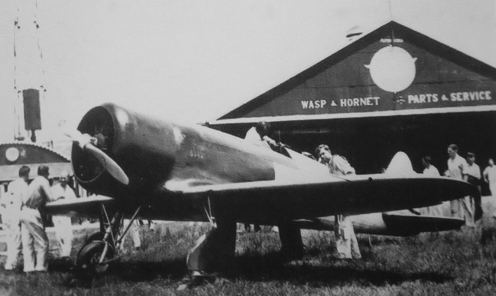
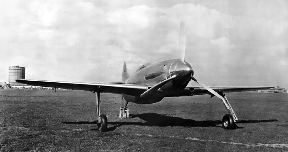
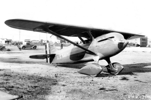
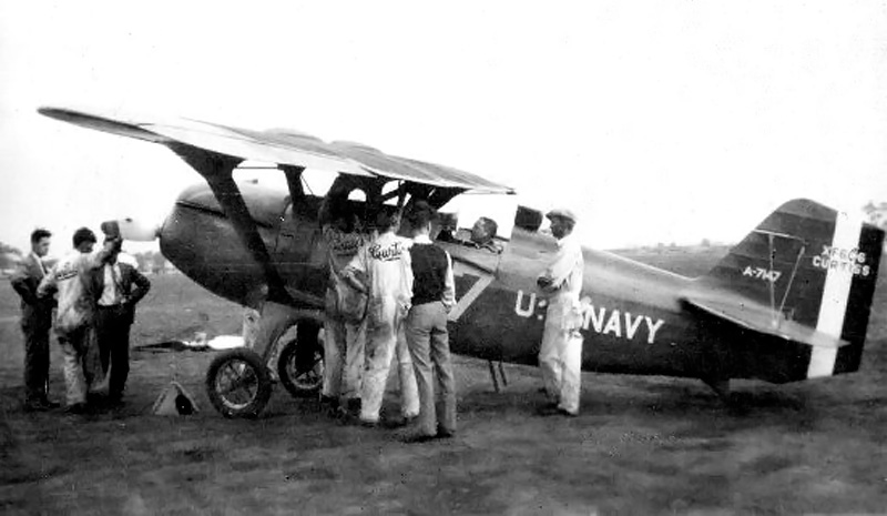
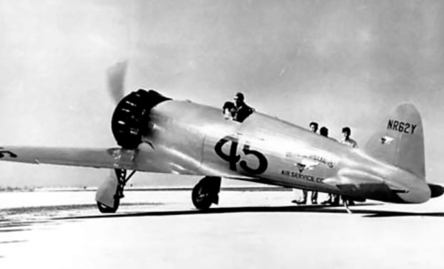
This photo of the Model 45 was taken shortly after the aircraft was built in Patterson, Louisiana in 1933. Note the smooth cowling covering the R-985 engine. Jimmie Wedell stands by the side of the aircraft.

Wedell took the Model 45 (registered as NR62Y) up for its first flight on 28 June 1933. The R-985 engine caused the aircraft to be underpowered and tail-heavy. Very little flight testing was accomplished because Wedell had entered the Model 45 in the Bendix Trophy Race, which was scheduled for 1 July. The 1933 race was run from New York to Los Angeles. Departing for New York, Wedell made it from Patterson, Louisiana to Atlanta, Georgia (about 500 miles / 805 km) before he turned back. Wedell decided the aircraft would not be competitive with its current engine. Instead, he flew a Model 44 (No. 44) and finished the race in second place, behind Roscoe Turner in his Wedell-Williams Model 44 (No. 2).

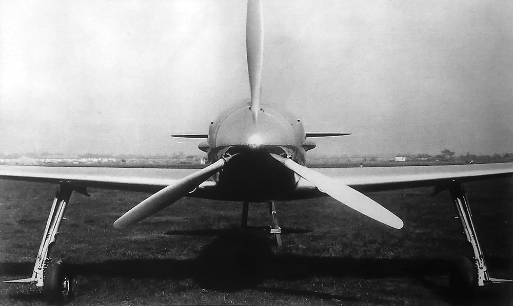
With the R-1535 still delayed, a nine-cylinder, 800 hp (597 kW) P&W R-1340 Wasp Sr. engine was installed on the Model 45 in place of the smaller engine. The R-1340 provided sufficient power for the aircraft and restored its proper balance. While the two engines used the same mounts, the R-1340 had a larger diameter than the R-985 and required a new cowling. The smooth cowling covering the R-985 engine was replaced by a larger cowling with bumps around its diameter to provide clearance for the engine’s rocker covers. The same engines were used in the Model 44, so the entire engine package (including cowling) could be swapped between the aircraft. An 8 ft 2 in (2.5 m) diameter, variable-pitch propeller was also installed.

Wedell-Williams Model 45 front

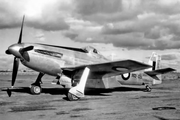
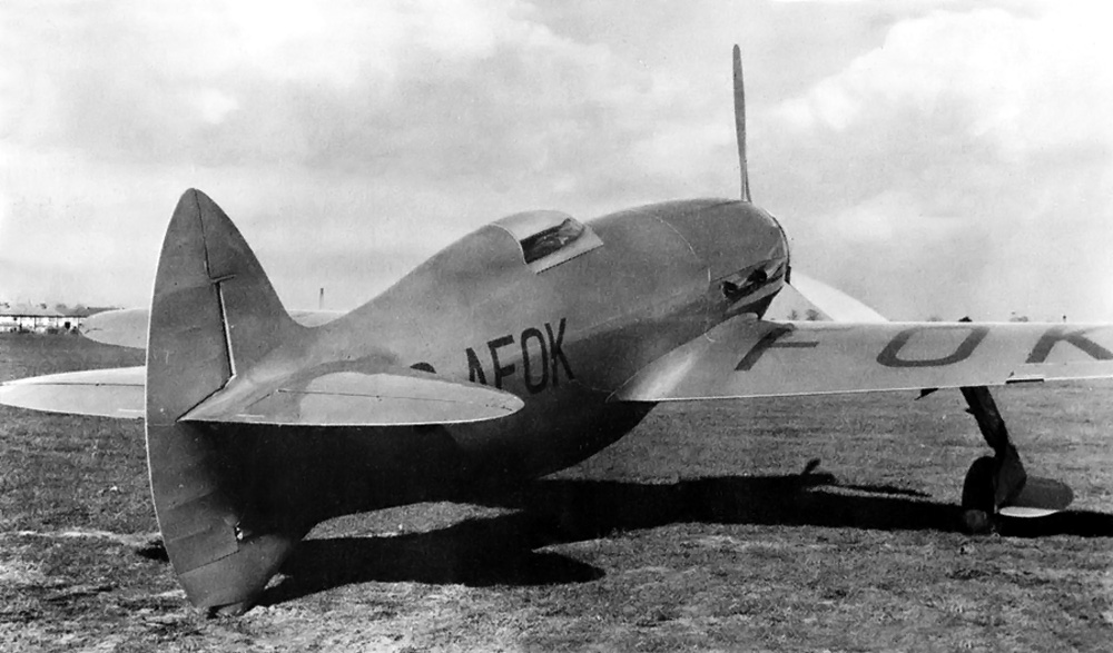
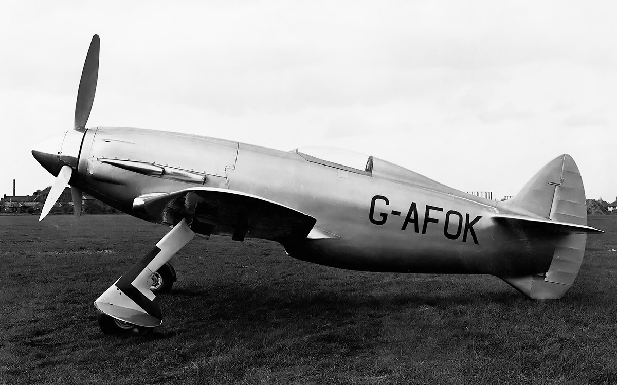
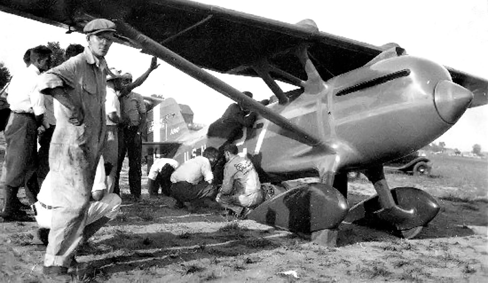
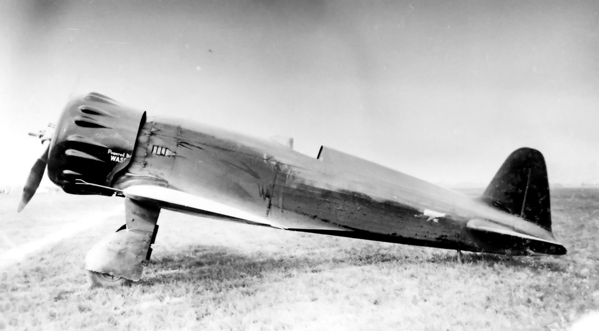
The Model 45 with its R-1340 engine installed. Note the bumps on the cowling that provided clearance for the engine’s rocker covers. The engines used in the Model 45 and Model 44 (No. 44) racer were interchangeable.

The Model 45 made its race debut at the Pan American Air Races held during the dedication of Shushan Airport (now New Orleans Lakefront Airport) in February 1934. Wedell flew the Model 45 to a new speed record over a 100 km (62 mi) course, averaging 264.703 mph (425.998 km/h), with the fastest lap over 266 mph (428 km/h). Wedell reported that he flew the distance at less than full power.

After the record run, Wedell-Williams Air Service began work to prepare their aircraft for the 1934 Bendix and Thompson Trophy Races, respectively scheduled for 31 August and 4 September. But disaster struck on 24 June 1934; Jimmie Wedell was killed when the de Havilland Gypsy Moth he was piloting crashed shortly after takeoff. Wedell was with a student pilot but had control of the aircraft. The student escaped with only minor injuries. The loss of head designer Jimmie Wedell was a major blow to Wedell-Williams Air Service, but the company continued to plan for the upcoming races.

Wedell-Williams Model 45 Jimmie

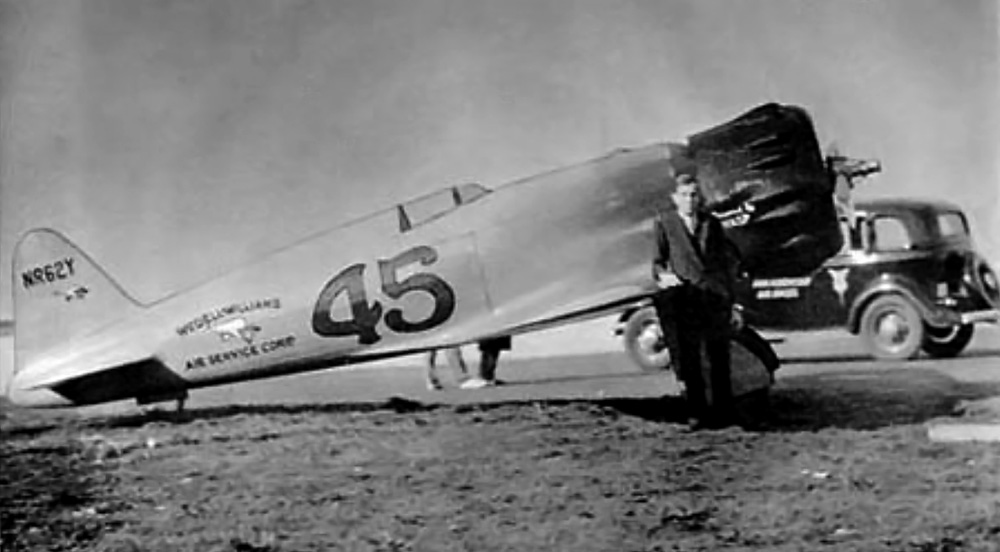
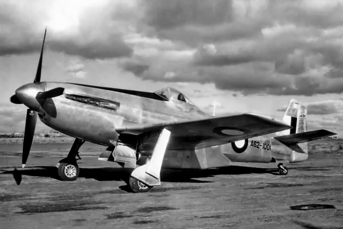
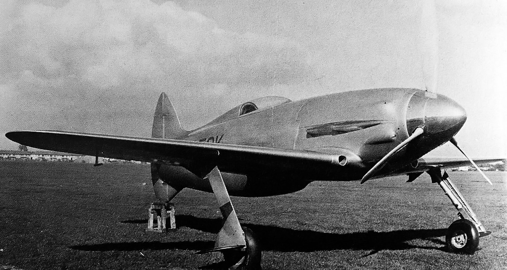
Jimmie Wedell stands by the Model 45. Note the doors for the retractable tail skid.

Experienced Wedell-Williams pilot John Worthen flew the Model 45 in the Bendix Trophy Race from Los Angles, California to Cleveland, Ohio. Worthen led the race, followed by Doug Davis flying Wedell-Williams Air Service’s other racer, a Model 44 (No. 44). Worthen, in the Model 45, had a comfortable lead when he became lost and overflew Cleveland by 100 miles (160 km). Worthen landed and refueled in Erie, Pennsylvania and then flew to Cleveland; he landed 36 minutes behind Davis. Had he not overflown Cleveland, Worthen and the Model 45 would have easily won the Bendix race; the trip to Erie added over 50 minutes to his total time. Even with the delay, the Model 45 had averaged 203.213 mph (327.040 km/h) in the Bendix Trophy Race.

In the Shell Speed Qualification heat (Group 3) for the Thompson Trophy Race, Worthen and the Model 45 placed third at 292.141 mph (470.156 km/h), coming in behind the Model 44 racers of Davis (No. 44) at 306.215 mph (492.805 km/h) and Roscoe Turner (No. 57) at 295.465 mph (475.505 km/h). In the Shell Speed Dash Unlimited race, Worthen and the Model 45 achieved 302.036 mph (486.080 km/h).

Wedell-Williams Model 45

The size and weight of the Wedell-Williams Model 45 was more suited for cross-country racing than pylon racing. It would have won the 1934 Bendix race had it not been for a navigation error. The Model 45 is barely an aviation footnote since it was flown fewer than two years and never won a major race.

The Wedell-Williams Air Service team decided that the Model 44 (No. 44) had the greatest potential for the Thompson Trophy Race. This decision was made because of some instability the Model 45 exhibited in the pylon turns—perhaps because the aircraft was not fully refined due to Wedell’s death. The team had been swapping the R-1340 and R-985 engines between racers for various events, and now the R-1340 engine was installed in the Model 44 for the Thompson Trophy Race. The Model 45 would not be competitive with the R-985 engine, and it was withdrawn from the race.

During the Thompson Trophy Race, Davis and the Model 44 were comfortably in the lead when he cut a pylon. He went back to circle the pylon when the aircraft either stalled or experienced a structural failure. The Model 44 smashed into the ground, killing Davis instantly. The shocked Wedell-Williams Air Service team disassembled the Model 45 and shipped it back to Paterson; it never flew again.

Wedell-Williams Air Service was never able recover because tragedies continued to plague the company. On 18 July 1935, Walter Wedell and his passenger were killed in a crash while flying in a Brewster Aristocrat. On 19 May 1936, Harry Williams and John Worthen were killed in a crash after the engine in their Beech Staggerwing quit shortly after takeoff.

Wedell-Williams Model 45 Cleveland side

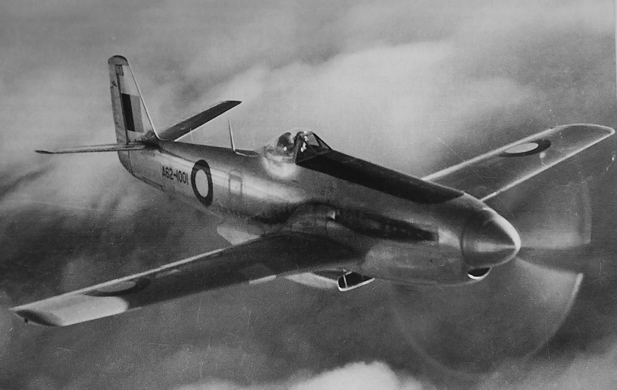
The Model 45 at the National Air Races in Cleveland, Ohio in September 1934. The unfortunate death of Jimmie Wedell seemingly cut short the aircraft’s development, and the Model 45 never reached its true potential. Its predecessor, the Model 44, continued to race until 1939, the last year of the races until after World War II.

The Model 45 was donated to Louisiana State University in 1936, but what happened to it is not known. It was most likely scrapped at some point. A full-scale replica Model 45 is in the Wedell-Williams Aviation and Cypress Sawmill Museum in Patterson, Louisiana.

Early in 1934, the Army Air Corps expressed interest in the Model 45 design suitably modified into a military pursuit aircraft. Initially, the Wedell-Williams Air Service proposal was rejected, but a subsequent proposal was approved, and a contract was issued on 1 October 1935 for detailed design work. The Wedell-Williams Air Service fighter was designated XP-34. The XP-34 had a wingspan of 27 ft 9 in (8.5 m) and a length of 23 ft 6 in (7.2 m). The 4,250 lb (1,928 kg) aircraft was forecasted to have a top speed of 286 mph (460 km/h) with a 750 hp (559 kW) P&W R-1535 or 308 mph (496 km/h) with a 900 hp (671 kW) P&W R-1830. The design of the XP-34 progressed until the aircraft was cancelled after the death of Williams in 1936, by which time its performance had been surpassed by other fighters.

Wedell-Williams Model 45 replica

The Wedell-Williams Model 45 replica in the Wedell-Williams Aviation and Cypress Sawmill Museum in Patterson, Louisiana. (Steffen Kahl image via Flickr)

Sources:
Wedell-Williams Air Service by Robert S. Hirsch and Barbara H. Schultz (2001)
Aircraft of Air Racing’s Golden Age by Robert S. Hirsch and Ross N. Hirsch (2005)
The Golden Age of Air Racing Pre-1940 by S. H. Schmid and Truman C. Weaver (1963/1991)
They Flew the Bendix by Don Diggins (1965)
Racing Planes and Air Races 1909-1967 by Reed Kinert (1967/1969)
http://www.crt.state.la.us/louisiana-state-museum/online-exhibits/louisiana-aviation-since-1910/jimmie-and-walter-wedell/

CAC CA-15

Commonwealth Aircraft Corporation CA-15 ‘Kangaroo’

By William Pearce

In July 1942, Australia’s Commonwealth Aircraft Corporation (CAC) endeavored to improve the performance of their CA-12 (and CA-13) Boomerang fighter by installing a 1,700 hp (1,268 kW) Wright R-2600 engine in place of the 1,200 hp (895 kW) Pratt & Whitney (P&W) R-1830. However, the needed modifications to the Boomerang airframe proved to be too substantial. Since the need for an improved fighter was still pressing, CAC embarked to design an entirely new aircraft in November 1942. This new fighter aircraft was designated CA-15.

CAC CA-15 flight

The impressive Commonwealth Aircraft Corporation CA-15 on a test flight. Note the patches on the wings that replaced the gun ports for the .50 cal machine guns.

The preliminary design of the CAC CA-15 incorporated a Pratt & Whitney R-2800 engine, and the aircraft somewhat resembled a cross between a Boomerang and a Focke-Wulf Fw 190A. As the design was developed, the CA-15 changed to resemble a Hawker Tempest II with squared-off wings and tail, but with a General Electric (GE) C turbosupercharger installed in the rear fuselage, similar to the Republic P-47 Thunderbolt.

By mid-1943, a redesign was needed because the proposed power plant, the 2,000 hp (1,491 kW) R-2800-21, was not available. CAC selected the 2,200 hp (1,641 kW) R-2800-10W with a two-stage, two-speed supercharger as the new engine. With the engine change, the turbosupercharger was deleted, and a water-cooled intercooler was added in a large fairing under the engine. A geared cooling fan would help draw air in through the tight-fitting cowling. By December 1943, the R-2800-10W-powered CA-15 was estimated to have a maximum speed of 365 mph (587 km/h) at sea level, 436 mph (702 km/h) at 25,000 ft (7,620 m), and an initial climb rate of 4,200 fpm (21.3 m/s).

CAC CA-15 R-2800-21

The Pratt & Whitney R-2800-21-powered CA-15, with cutaway to show the fuselage fuel tank. The turbosupercharger installation in the rear fuselage is not visible. In this early 1943 drawing, the CA-15 has a passing resemblance to the Hawker Tempest II.

The switch to the R-2800-10W engine also shifted the CA-15’s area of maximum performance from high altitude to low/medium altitude. At the time, CAC had obtained a license to produce the North American P-51D Mustang as the CA-17 and CA-18; CA-17s would be assembled from parts, and CA-18s would be CAC-produced aircraft. Lawrence Wackett, CAC’s General Manager, envisioned the CA-17/CA-18 filling the high altitude fighter role and the CA-15 covering low and mid altitudes. From mid-1943, CAC was focused on CA-17 assembly and CA-18 production, and progress on the CA-15 slowed as a result.

With many components for the prototype CA-15 under construction, CAC was disappointed to learn in May 1944 that the R-2800-10W was no longer in production. CAC found a suitable replacement in the form of the 2,800 hp (2,088 kW) R-2800-57. With this engine change, the CA-15 was back to incorporating a turbosupercharger—now a GE CH-5 housed in a deeper fairing under the engine. The R-2800-57-powered CA-15 was estimated to have a maximum speed of 400 mph (644 km/h) at sea level, 480 mph (772 km/h) at 28,000 ft (8,534 m), and an initial climb rate of 5,700 fpm (29.0 m/s).

CAC CA-15 R-2800-57

A mid-1944 drawing of the CA-15 powered by a R-2800-57 engine. While the top view of the aircraft has not changed much, the bulky fairing under the engine has been added to house the intercooler and turbosupercharger.

By August 1944, the CA-15 prototype was around 50 percent complete. It was at this time that CAC was informed that supplies of the R-2800-57 could not be guaranteed. CAC again looked for an engine suitable for the CA-15 fighter. CAC found a new engine in the Griffon 125, then being developed by Rolls-Royce (R-R). The water-cooled Griffon 125 had a two-stage, three-speed supercharger and turned a single rotation propeller. The engine was capable of producing 2,440 hp (1,820 kW). A redesign of the CA-15 cowling was completed, and a scoop to house radiators for the engine coolant and oil was incorporated under the aircraft. With these changes, the CA-15 resembled a P-51D Mustang, but the resemblance was coincidental. The Griffon 125-powered CA-15 was estimated to have a maximum speed of 405 mph (652 km/h) at sea level, 467 mph (752 km/h) at 18,000 ft (5,487 m), and 495 mph (797 km/h) at 26,500 ft (8,077 m). The initial climb rate dropped slightly to 5,500 fpm (27.9 m/s).

Unfortunately, the Australian War Cabinet cancelled the CA-15 in September 1944. However, CAC continued work on the CA-15 at a reduced pace while it worked with the War Cabinet to reinstate the program. This was done in December, pending the approval of the Aircraft Advisory Committee, which followed in February 1945.

Work on the CA-15 now continued at a quicker pace, but engine issues surfaced again. R-R would not be able to provide a Griffon 125 until late 1945 at the earliest (but probably later). The CA-15 was ready for its engine, and CAC did not want to wait. As a substitute, two 2,035 hp (1,517 kW) Griffon 61s were loaned to CAC, the first being shipped in April 1945. The Griffon 61 had a two-stage, two-speed supercharger. As the CA-15 neared completion in December 1945, R-R informed CAC that the Griffon 125 would not be produced. The CA-15 used the Griffon 61 as its final engine, and the aircraft was completed in early 1946.

CAC CA-15

The completed CA-15 with its Griffon 61 engine bore a striking resemblance to the P-51D Mustang. However, the aircraft’s general layout changed little from the early 1943 drawing completed before CAC obtained a license for P-51 (CA-17/CA-18) production. Note the recessed engine exhaust stacks for improved aerodynamics.

The CA-15 was an all-metal aircraft of stressed-skin construction. The flaps and fully retractable gear were hydraulically operated. Various offensive armament combinations were considered, including four 20 mm cannons with 140 rpg, but six .50 cal machines guns were ultimately fitted with 250 rpg (various sources, including CAC documents, list 260, 280, or 290 rpg). The guns were not installed until a few months after the aircraft’s first flight. Underwing provisions existed for two 1,000 lb (454 kg) bombs or two 120 gal (100 imp gal / 454 L) drop tanks or 10 rockets.

In its final form, the CA-15 had a 36 ft (11 m) wingspan and was 36 ft 3 in (11 m) long. The aircraft’s internal fuel capacity was 312 gal (260 imp gal / 1,182 L), and it had a maximum range of 2,540 mi (4,088 km) with two drop tanks. The CA-15 weighed 7,540 lb (3,420 kg) empty, 10,764 lb (4,882 kg) with a normal load, and 12,340 lb (5,597 kg) at maximum overload. The Griffon 61-powered CA-15 had a maximum speed of 368 mph (592 km/h) at sea level, 448 mph (721 km/h) at 26,400 ft (8,047 m), and 432 mph (695 km/h) at 32,000 ft (9,754 m). The aircraft’s initial climb rate was 4,900 fpm (24.9 m/s), and it had a ceiling of 39,900 ft (12,162 m). The Griffon engine turned a 12 ft 6 in (3.81 m) diameter Rotol four-blade, wooden, constant-speed propeller. Initially, a 12 ft 1 in (3.68 m) propeller was used, the result of a damaged tip necessitating the blades being cut down. But a full-size propeller was fitted later during the flight test program.

CAC CA-15 side

This photo of the CA-15 illustrates the tailplane’s 10 degrees of dihedral and the relatively good view the pilot had over the nose of the aircraft.

Assigned serial number A62-1001, the CA-15 began taxi tests in February 1946. After a few modifications, the aircraft first flew on 4 March 1946 with Jim Schofield at the controls. The initial test flights went well, although the ailerons were noted as being heavy. Aileron control was improved, and numerous other refinements were made. Throughout the test flights, the CA-15 proved itself as an easy to fly aircraft with excellent performance and very good visibility.

After 16.5 hours of flying time, the CA-15 was handed over to the Royal Australian Air Force (RAAF) Aircraft Performance Unit (APU) No. 1 on 2 July 1946 for further flight testing. While at APU No. 1, the landing gear struts were over-pressurized, causing the CA-15 to bounce badly during taxi tests. The hopping action of the aircraft earned it the unofficial nickname “Kangaroo,” which has lasted over the years. Unfortunately, on 10 December 1946, a test gauge failed and resulted in the loss of all hydraulics. With no flaps and the unlocked gear partially extended, Flt. Lt. Lee Archer was forced to make an emergency landing that damaged the aircraft’s scoop and destroyed the wooden propeller. The failed gauge should have been removed before the aircraft was handed over to the RAAF. At the time, the CA-15 had 43.25 flying hours, and the damage was not too severe. However, with the war over and jets coming into service, there was no possibility of the CA-15 going into production. As a result, repairs to the one-off prototype were slow, after finally being approved in April 1947.

CAC CA-15 taxi

The CA-15 after a test flight. Note the scoop’s partially open cooling air exit flap. The aircraft in the background are most likely CAC-assembled CA-17s (P-51Ds), as the first CA-18 was not completed until 1947 (after the CA-15 was damaged).

CAC had repaired the CA-15’s airframe by October 1947, and the aircraft awaited a new propeller and radiator, which were the responsibility of the RAAF. The radiator was ready by February 1948, and the propeller followed in March. The CA-15 was returned to APU No. 1 on 19 May 1948. Later that month, the CA-15 grabbed headlines by achieving 502 mph (808 km/h) in a test flight over Melbourne, Victoria, Australia on 25 May 1948. This speed was recorded after Flt. Lt. Archer had leveled off at 5,000 ft (1,524 m) following a modest dive from 9,000 ft (2,743 m).

By February 1950, R-R wanted the two Griffon 61 engines back. In addition, there was no inventory of spare parts or any practical reason to continue flight testing of the CA-15. The engine was removed, and the CA-15 was scrapped, bringing an end to the highest performance aircraft ever designed and built in Australia.

CAC CA-15 rear

The CA-15 “Kangaroo” was a powerful fighter with performance rivaling that of the best piston-powered aircraft. Sadly, it was built too late for action in World War II and at a time when jet aircraft were the undeniable future.

Sources:
Wirraway, Boomerang & CA-15 in Australian Service by Stewart Wilson (1991)
Wirraway to Hornet by Brian L Hill (1998)
– “Commonwealth CA-15: The ‘Kangaroo’ Fighter” by David Donald Wings of Fame Volume 4 (1996)
R-2800: Pratt & Whitney’s Dependable Masterpiece by Graham White (2001)

Coanda 1911 Monoplane prop

Coandă 1911 Monoplane

By William Pearce

Romanian Henri Marie Coandă is perhaps best known for observing the way a stream of fluid (such as air) is attracted to and will flow over a nearby surface. This component of fluid dynamics became known as the Coandă Effect. Coandă recognized this phenomenon while testing his first aircraft, built in 1910. This aircraft had a unique propulsion system that Coandă called a turbo-propulseur, and it is recognized as the first “jet” aircraft. A four-cylinder, 50 hp Clerget engine was used to power a rotary compressor that provided thrust. While there is some debate about the validity of the aircraft’s first and only flight and its subsequent destruction, the aircraft was certainly built to be propelled by a jet of fast-flowing air.

Coanda 1911 Monoplane front

Henri Coandă’s 1911 monoplane at the Concours Militaire in Reims, France in October 1911. Note the tandem main gear wheels.

Coandă’s second aircraft was built in France and completed in 1911. It utilized some salvaged and spare parts from the 1910 aircraft. The 1911 aircraft was originally designed to use a turbo-propulseur, but it was finished with a conventional propeller. The aircraft’s engine arrangement, however, was not conventional.

The 1911 aircraft was a rather large monoplane with a parasol wing mounted above the cockpit. A small lifting surface with a nickel steel spar joined the two main landing gear which were each comprised of two tandem wheels. Each main gear wheel set was encased in a large fairing. A single vertical strut made of nickel steel extended above each gear fairing and supported the wing. The wings had a nickel steel spar and were covered by fabric. The aircraft’s roll control was achieved by wing warping. Coandă’s 1911 aircraft had a cruciform tail similar to that used on the 1910 aircraft. The fins of the tail formed an X, and each fin had a trailing control surface that acted as both a rudder and an elevator.

Coanda-1911-Monoplane

This photo shows a detailed view of the Gnome installation on Coandă’s 1911 aircraft. Note the various struts and braces used on the aircraft. The aluminum-covered front fuselage is easy distinguished from the plywood-covered cockpit section. The aircraft’s control wheel can just be seen at right.

A rectangular support structure was formed by the upper and lower spar and the vertical struts above the wheels. The fuselage was suspended in this support structure by a series of brace wires and small struts. Additional wire bracing and struts supported the rest of the aircraft’s structure. Except for where the engines were mounted, the fuselage had a circular cross section that narrowed to a point at the tail. The front of the fuselage was covered by aluminum sheeting, the cockpit section was covered by plywood sheeting, and the rear of the aircraft was fabric-covered.

Perhaps the most unusual feature of Coandă’s 1911 monoplane was its engine installation and propeller drive. At the front of the aircraft were two Gnome 7 Gamma rotary engines. The seven-cylinder engines had a 5.1 in (130 mm) bore, a 4.7 in (120 mm) stroke, and a total displacement of 680 cu in (11.1 L). The 7 Gamma produced 70 hp (52 kW) at 1,200 rpm and weighed 194 lb (88 kg).

Coanda 1911 Monoplane engines

This photo shows an engine and gearbox arrangement similar to that used on Coandă’s 1911 monoplane. It is not clear when this photo was taken, but it may have been at the Salon de l’Aeronautique in Paris, France held mid-December 1911 through early January 1912. (Harry Stine image via New Fluid Technology)

The engines were installed front-to-front with their crankshafts perpendicular to the aircraft’s fuselage. While the engines’ cylinders were exposed to the slipstream for cooling, the front of the engines were enclosed within the fuselage. Mounted between the engines was a gearbox that drove a propeller shaft. The propeller shaft extended to the front of the aircraft where it drove a four-blade propeller. The engines and gearbox were mounted to a steel frame. Coandă claimed that the aircraft could fly with just one engine operating.

Most likely, the engines turned in opposite directions relative to each other. While this arrangement would cancel out the gyroscopic effects of the rotary engines along the pitch axis, it would induce some tendency to roll, even if just slightly. Some sources indicate the engines were “handed” —they rotated the same direction relative to each other. In addition to the complications in making a rotary engine run “backward,” the “handed” engine configuration would create a noticeable pitch moment on the aircraft as the engines were throttled (blipped), but it would also alleviate any tendency for the aircraft to roll. However, an early sketch of the engine arrangement indicates “handed” engines were not installed, and that a simple beveled gear arrangement was used to transfer power from the engines to the propeller shaft. Additionally, the transfer gearbox did not appear to be of sufficient size to accommodate the differential gearing needed for a “handed” engine arrangement.

Coanda 1911 Monoplane side

Note the cruciform tail and its control surfaces in this photo of the Coandă 1911 monoplane. Also, the plywood-covered cockpit section can be easily distinguished from the fabric-covered rear fuselage.

The 1911 Coandă monoplane had a wingspan of 53 ft 6 in (16.3 m) and a length of 41 ft (12.5 m). The aircraft had an empty weight of 1,036 lb (470 kg) and a maximum weight of 2,756 lb (1,250 kg). Two fuel tanks of around 30 gallons (115 L) each were housed in the center section of the wing. Reportedly, the aircraft could accommodate a pilot and two passengers. The estimated speed of the 1911 monoplane was 81 mph (130 km/h).

Coandă’s 1911 monoplane was tested in the Concours Militaire (Military Competition), held in Reims, France in late October 1911. Georges de Boutiny flew the aircraft, but it reportedly did not meet performance expectations. Later, wing extensions were added to the wheel fairings, turning the aircraft into a sesquiplane. Along with additional wire bracing, a vertical strut connected the end of the wing extension to the upper wing.

Coanda 1911 Monoplane prop

Mechanic George Bonneuil checks a Gnome engine as pilot George de Boutiny looks on from the cockpit. (Harry Stine image via New Fluid Technology)

A Coandă aircraft catalog from 1911 offered both the monoplane and sesquiplane versions of the aircraft with either 50 hp (37 kW) Omega or 70 hp (52 kW) Gamma Gnome rotary engines. It appears that only the single prototype of the Coandă 1911 aircraft was built, and exactly what happened to it is not known. The 1911 aircraft faded into history, and Henri Coandă went on to build other aircraft and further explore fluid dynamics.

Note: Some claim that Coandă’s 1911 aircraft was the first twin-engine aircraft. However, at least four other twin-engine aircraft preceded it in flight: the Daimler Lutskoy No. 1 (flew 10 March 1910, or possibly earlier), Edward Andrew’s twin (flew early 1910), Roger Sommer’s twin (flew 27 September 1910), and the Queen Speed Monoplane (flew 10 July 1911).

Coanda 1911 Monoplane extensions

This photo shows Coandă’s 1911 aircraft with its wing extensions. The extensions effectively made the aircraft a sesquiplane. Additional struts and braces for the extensions can be seen. Note the three people in the cockpit and also the warp of the wing tip.

Sources:
Henri Coandă and His Technical Work During 1906-1918 by Dan Antoniu, et al (2010)
French Aeroplanes before the Great War by Leonard E. Opdycke (1999)
Romanian Aeronautical Constructors 1905-1974 by Gudju, Iacibescu, and Ionescu (1974)
Henri Coanda: The Facts by New Fluid Technology (4.3 MB pdf)
http://flyingmachines.ru/Site2/Crafts/Craft28597.htm
http://en.wikipedia.org/wiki/Coand%C4%83-1910
http://en.wikipedia.org/wiki/Henri_Coand%C4%83
http://www.secretprojects.co.uk/forum/index.php/topic,18780.15.html

Napier-Heston Racer front 3-4 2

Napier-Heston Racer

By William Pearce

Near the end of World War I, D. Napier & Son built one of the most outstanding aircraft engines of all time: the 12-cylinder Lion. Lion production continued through the 1920s and 1930s, and other Napier aircraft engines did not achieve a level of success anywhere near that of the Lion. In the 1930s, Major Frank Halford was the head aircraft engine designer at Napier and was working on H-type engines. Compared to contemporary aircraft engines, Halford’s new engines used a smaller cylinder bore and stroke and ran at a higher rpm. In the late 1930s, Halford’s latest engine was the Sabre—a sleeve valve engine with 24 cylinders of 5.0 in (127 mm) bore and 4.75 in (121 mm) stroke. The Sabre displaced 2,238 (36.7 L) and was capable of over 2,000 hp (1,491 kW) and speeds up to 4,000 rpm.

Napier-Heston Racer front 3-4

The Napier-Heston Racer’s sleek lines and wide-track undercarriage are apparent in this view of the aircraft taken at the Heston Airport.

Napier wanted a way to demonstrate their new aircraft engine to the world. In its earlier days, the Lion had powered aircraft used to set world speed records. Since 1937, the Germans had held the landplane 3 km (1.86 mi) world speed record at 379.38 mph (610.55 km/h), and since 1934, the Italians had held the absolute 3 km (1.86 mi) world speed record at 440.682 mph (709.209 km/h). Napier felt a specially designed aircraft powered by a Sabre engine would be capable of setting a new speed record at over 480 mph (772 km/h), beating both the Germans and Italians. Not only would this achievement be great marketing, it would also bring the record back to Britain and embarrass Hitler’s Germany and Mussolini’s Italy.

Under lead designer Arthur E. Hagg, Napier laid out its racer design in mid-1938. Hagg previously designed the de Havilland DH.91 Albatross transport, and the two aircraft share some family resemblance. The racer’s sole purpose was to break the 3 km (1.86 mi) world speed record, and it was not intended as a testbed for the Sabre engine. The British Air Ministry was unwilling to financially support the project, but Lord Nuffield (William Richard Morris) stepped forward to independently fund the construction of two aircraft. In addition, a number of vendors donated parts and services or offered them at cost. Since Napier did not have the resources to construct the racer, the Heston Aircraft Company was selected to build the aircraft in late 1938. The Heston team was led by George Cornwall. The association between Napier and Heston gave the aircraft its popular name: the Napier-Heston Racer. The aircraft is also known as the Nuffield-Napier-Heston Racer, the Heston J.5 High-Speed Aircraft, and the Heston Type 5 Racer.

Napier-Heston Racer rear 3-4

The Napier-Heston Racer was painted silver with dark blue registration letters. Many layers of aircraft dope were applied to the birch ply sheeting that made up the exterior of the aircraft; this created a surface free from even the most minor of imperfections.

To expedite construction, the Napier-Heston Racer was built almost entirely of wood. The wing spars were made from compregnated wood of multiple laminations bonded with resin under high pressure. The fuselage frame and stringers and wing ribs were made of spruce. The wings and fuselage were covered with birch ply sheets. Split flaps were incorporated into the wings. The control surfaces had aluminum alloy frames and were covered with fabric. A variable-ratio control system was designed for the elevator. This system kept the elevator movements small when the control stick was near the neutral position. As the control stick was moved farther from neutral, the relative elevator movement became greater. This system was employed so that very precise elevator movements could be achieved at high speeds.

The Napier-Heston Racer was fitted with one of the first six Sabre I prototype engines, but its boost was increased. The standard Sabre I engine produced 2,000 hp at 3,700 rpm, but the racer’s engine produced 2,450 hp (1,827 kW) at 3,800 rpm. The racer had a 10 ft 9 in (3.28 m) diameter, metal, three-blade, de Havilland constant-speed propeller. Wing root intakes led to the engine’s supercharger. A radiator was housed in a duct under the aircraft. The radiator’s upper and lower surfaces were sloped back and formed a deep V in the duct. After air passed through the radiator, it was expelled under the horizontal stabilizer on both sides of the tail. A channel above the radiator skimmed off the turbulent boundary layer, allowing it to bypass the radiator. The wide-track (14.8 ft / 4.5 m) main gear retracted fully into the wings, and a small tail skid was incorporated into the fixed fin of the tail. After many layers of aircraft dope were applied, the fit and finish of the racer was near perfection.

Napier-Heston Racer left

The rather small size of the Napier-Heston Racer is illustrated in this photo. The radiator’s intake duct can be seen under the aircraft, and its exit duct under the horizontal stabilizer. Note the bulges in the cowling to allow clearance for the Sabre’s cylinder banks.

Between the engine and fully enclosed cockpit was a 73 gallon (276 L) fuel tank. At full throttle, the aircraft’s endurance was only 18 minutes. The racer had a wingspan of 32 ft (9.75 m), a length of 24 ft 7 in (7.50 m), and a height of 11 ft 10 in (3.61 m). Its fully loaded weight was 7,200 lb (3,267 kg). All tolerances were kept to a minimum, and the racer was highly polished to remove any imperfections. The aluminum engine cowling had four bulges to allow clearance for the Sabre’s cylinder banks. The cowling sealed so tightly that small air vents were installed on the bulges to ensure that no combustible vapors built up in the engine compartment.

The first flight of a Sabre engine occurred on 31 May 1939. The engine was installed in a Fairey Battle flown by Chris Staniland. The Sabre-powered Battle had accumulated a number of hours before the special engine in the Napier-Heston Racer was first run on 6 December 1939. The racer was painted silver, with the registration of G-AFOK painted in dark blue. Taxi tests began on 12 March 1940 at Heston Airport. The engine and taxi test did not reveal any issues with control or engine cooling.

The Napier-Heston Racer’s first flight was delayed by weather but finally occurred on 12 June 1940. Squadron Leader G. L. G. Richmond was at the controls and flew the aircraft off from the 3,900 ft (1,189 m) grass field at Heston Airport. Reportedly, Richmond chose to make this flight without the canopy in place. Shortly after liftoff, the Sabre engine rapidly overheated, and Richmond tried to quickly bring the plane in for a landing. Sources disagree on exactly what happened next.

Napier-Heston Racer front

Two of the small engine compartment vents can just be seen on the upper bulges of the cowling. The exterior of the aircraft was kept as aerodynamically clean as possible.

Some sources state that Richmond was preoccupied with the emergency and was also being scalded by the overheated cooling system. They claim that he may have experienced some difficulty mastering control of the variable-ratio elevator, as he had almost touched down after a steep approach when the aircraft rose sharply back into the air and stalled. Other sources point out that the racer did not exhibit any cooling issues during the numerous ground engine runs and that Richmond was scalded when the coolant pipes burst as a result of the hard landing after the stall. They contend that the aircraft’s elevator became ineffective as a result of low speed and that it was possibly in the wings’ turbulent airflow during the steep pitch up before the stall. While some sources state the Sabre engine seized, others report the ignition was on and the engine was running but that Richmond did not advance the throttle because of its overheated state.

Richmond’s flight in the Napier-Heston Racer was only about six minutes, and he never retracted the gear. After liftoff, he immediately brought the aircraft around for landing. Richmond’s actions indicate he felt something was wrong very early on. While a burst cooling pipe would explain the cooling issues and Richmond’s scalding, and control issues with the elevator would explain the odd altitude deviations in the aircraft’s final moments, the exact issues and sequence of events may never be known.

Napier-Heston Racer front 3-4 2

The wing root intake scoops that provide air to the Sabre engine can clearly be seen in this photo. Two three-into-one exhaust manifolds on each side of the racer collected the Sabre’s exhaust gases.

The end result was that the Napier-Heston Racer stalled about 30 ft (9 m) above the grass runway and hit the ground hard. The impact broke the landing gear, the left wing, and the rear fuselage just behind the cockpit. Fortunately, Richmond was able to walk away from the wreck. With the war against Germany underway, no attempt was made to repair the Napier-Heston Racer. The racer’s Sabre engine was not badly damaged. It was rebuilt and installed in a production Hawker Typhoon that was used during the war. Although the second racer, registered as G-AFOL, was around 60% complete, it was never finished. The Napier-Heston Racer project had cost Lord Nuffield £50,000 to £100,000.

Between the time the Napier-Heston Racer was conceived and its first flight, Germany had increased the absolute world speed record to 469.221 mph (755.138 km/h). However, the Chief Technician and Aerodynamicist at Heston Aircraft, R. A. Clare, had estimated that the Napier-Heston Racer could achieve a maximum of 508 mph (818 km/h) over the 3 km (1.86 mi) course. While the true capabilities of the racer will never be known, attempts have been made to create a flying replica. Due to the high cost of such a project and the extreme rarity of Sabre engines, for now, a Napier-Heston Racer replica remains just a dream.

Napier-Heston Racer right side

The Napier-Heston Racer ready to fly at the Heston Airport. It is unfortunate that the aircraft never had a chance to demonstrate its true potential.

Sources:
– “The Napier-Heston Racer” by Bill Gunston Aeroplane Monthly (June 1976)
– “Napier-Heston Racer postscript” Aeroplane Monthly (August 1976)
– “A Co-operative Challenger” Flight (15 April 1943)
– “The Heston Napier Monoplane” by H. J. Cooper The Aero Modeller (August 1943)
By Precision Into Power by Alan Vessey (2007)

Curtiss XF6C-6 Page Navy Racer 18-08-1930

Curtiss XF6C-6 Page Navy Racer

By William Pearce

After World War I, it was clear that aircraft were vehicles with great potential, and not just playthings for the rich or eccentric. A rivalry built up between the United States Marine Corps, Navy, Army, and civilians as they each explored aviation in the 1920s. The military branches competed with each other in various races, with floatplanes switching to wheels for land-based races and wheeled aircraft switching to floats for sea-based races.

Curtiss XF6C-6 Page Navy Racer

The Curtiss XF6C-6 Page Navy Racer created for the 1930 Thompson Trophy Race.

US Marine Corps Captain Arthur H. Page flew his float-equipped Curtiss F6C-3 racer to victory in the Curtiss Marine Trophy Race on 31 May 1930, besting the rest of the field, which consisted entirely of Navy pilots. The F6C-3 was a member of the Curtiss Hawk family of biplane fighter aircraft, which had been steadily developed since the first Hawk was built for the Army in 1923. The F6C-3 had a fuselage and tail made of welded steel tubing and covered with fabric. The wings had a spruce structure and were fabric covered. Page’s F6C-3 (serial A-7147) had been cleaned up aerodynamically to achieve every bit of speed possible, and it averaged a race-record 164.08 mph (264.06 km/h).

Page knew he would need more speed from the F6C-3 if he were to have any chance in the inaugural Thompson Trophy Race, which would be held on 1 September 1930 during the National Air Races. In the 1929 National Air Races, civilian Doug Davis in the privately-built Travel Air “Mystery Ship” beat both the Army and Navy Hawk entries when he averaged 194.9 mph (313.7 km/h) over the course of the race. Page wanted to avenge this humiliating defeat and set a new standard of speed in the process. Page won the support of the Navy Bureau of Aeronautics, and Curtiss went to work in June 1930 to turn the F6C-3 (serial A-7147) into a pure air racer. This was the same aircraft in which Page won the Curtiss Marine Trophy Race.

Curtiss F6C-3 Marine Race Page

The Curtiss F6C-3 Hawk that Arthur Page flew to victory in the 1930 Curtiss Marine Trophy Race. For that race, the radiator intake was modified, and the radiator housing was faired back to the tail. The fuel filler cap and pilot’s headrest were also faired to improve the aircraft’s aerodynamics. This aircraft was extensively modified into the XF6C-6 racer.

The modifications made to the F6C-3 were so extensive that the aircraft was redesignated XF6C-6. With the exception of the tail, the XF6C-6 bore no resemblance to the F6C-3. The 450 hp (336 kW) Curtiss D-12 engine was removed and replaced by a supercharged 750 hp (559 kW) Curtiss Conqueror engine. The Conqueror had a 5-1/8 in. (130 mm) bore and a 6-11/32 in (161 mm) stroke. The engine’s total displacement was 1,570 cu in (25.7 L), and it turned an 8 ft (2.4 m), two-blade, steel, ground-adjustable propeller.

The aircraft’s lower wing was removed, and the upper wing was moved back several inches. The now-parasol wing was mounted to the fuselage on streamlined struts. The wing had a duralumin leading edge, and brass surface radiators made up most of its upper and lower surfaces. Coolant was taken from the engine and flowed through pipes installed in the front wing struts. The coolant then flowed into header tanks along the wing’s leading edge and through the surface radiators. At the rear of the wing, the coolant was collected and flowed back to the engine via pipes that ran through the rear struts.

Curtiss XF6C-6 Page Navy Racer 18-08-1930

The completed Curtiss XF6C-6 on 18 August 1930. Even though it is the same aircraft, the modifications have made it unrecognizable from its F6C-3 origins.

The wing radiators enabled the chin radiator to be discarded, and a very streamlined aluminum engine cowling was fitted over the Conqueror engine. The landing gear was housed in aerodynamic wheel pants and attached to the fuselage by a single streamlined strut. The XF6C-6’s cockpit had metal panels on each side and was partially enclosed by a cushioned cover positioned over the pilot’s head. The panels hinged down, and the cover hinged to the rear for pilot entry and exit. The aircraft’s fuselage was aerodynamically cleaned up and recovered.

The XF6C-6 racer is often referred to as the “Page Racer” or “Navy Page Racer.” The aircraft had a polished navy blue fuselage and lower wing surface, and the upper wing surface was yellow. The exposed brass of the surface radiators was polished. The aircraft had a wingspan of 31 ft 6 in (9.6 m), a length of 23 ft 0 in (7.0 m), and a height of 8 ft 11 in (2.7 m). The XF6C-6 had an empty weight of 2,600 lb (1,179 kg) and a loaded weight of 3,130 lb (1,420 kg). Its range was 270 mi (435 km). The XF6C-6 had a cruising speed of 200 mph (322 km/h) and an estimated top speed of 250 mph (402 km/h).

Curtiss XF6C-6 Page Navy Racer cockpit

This image of the XF6C-6 racer shows the hinged cockpit sides and cover. The aircraft has its Thompson Trophy Race number (27) applied, and no carburetor scoop is visible. Note the exposed wheels.

Construction for the XF6C-6 was rapid, and the aircraft was completed by mid-August. The initial flight testing went well, but some signs of flutter were encountered at high speeds. Originally, a louvered panel on top of the engine cowling supplied air to the engine’s carburetor. A raised scoop replaced the louvers before the Thompson Race. However, some sources indicate the scoop was discarded and the louvered panel was reinstalled for the actual race.

The aircraft made its public debut for the Thompson Trophy Races held at the Curtiss-Reynolds airport (later Naval Air Station Glenview and now a shopping center) south of Chicago, Illinois. Captain Page in the XF6C-6 was the only military entrant in the field of seven. The XF6C-6 was larger than the other Thompson Trophy racers, but it was also more powerful.

Page was the first airborne, followed by the other racers at 10 second intervals. By the time the last racer took off, Page had almost completed his first lap of the five mile (8 km) circuit. The XF6C-6 was obviously much faster than the other racers; the only question was whether or not it would last the 20 laps. By the third lap, Page began lapping the slower aircraft. Page turned lap after lap at well over 200 mph (322 km/h), and the XF6C-6 went on to lap the entire field.

Curtiss XF6C-6 Page Navy Racer rear scoop

This image shows the Curtiss XF6C-6 racer again with its race number, but the carburetor scoop is in place. Also visible is the hand crank (and its shadow) used to start the engine. Note how the aircraft’s seams have been taped over to reduce drag.

On the 17th lap, Page went high and turned inside the course as he neared the home pylon. The XF6C-6 never straightened from the turn; it smashed into the ground as the 75,000 spectators looked on. Page survived the crash and was taken to a hospital where he died from his injuries later that night. Fellow race pilot Jimmy Haizlip, who had just been lapped by Page, noted the XF6C-6’s propeller was barely turning before the ground impact. In addition, the ignition switch was found in the “Off” position. It is believed that Page had been slowly overcome by carbon monoxide fumes from the exhaust that built up in the tight cockpit. Although too late, he realized the situation and shut off the engine in an attempt to get fresh air. He then turned inside the course to seek a safe landing but became incapacitated and crashed. Unfortunately, carbon monoxide poisoning was a fairly common occurrence in early aviation, and Page was one of many aviators who succumbed to exhaust fumes in the cockpit.

The XF6C-6 had turned each lap between 207 and 219 mph (333 and 352 km/h) before the crash (some sources state the average speed was 219 mph / 352 km/h). Speed Holman in the Laid Solution went on to win the race at 201.91 mph (324.94 km/h). With the death of Captain Page, American military aircraft were no longer entered in air races until after World War II. Even then, civilian and military racers participated separately (primarily because of the military’s switch to jet aircraft).

Curtiss XF6C-6 Page Navy Racer front scoop

The XF6C-6 during an engine run-up. This image provides a good view of the carburetor scoop and taped seams. The bulges on top of the wing are expansion tanks for the surface radiators.

Sources:
Curtiss Aircraft 1907-1947 by Peter M. Bowers (1979/1987)
Racing Planes & Air Races 1909-1967 by Reed Kinert (1967)
– “Captain Page and the 1930 Thompson Trophy Race” by Jimmy Halzip The Golden Age of Air Racing (1963/1991)
Thompson Trophy Racers by Rodger Huntington (1989)
http://1000aircraftphotos.com/Contributions/Shumaker/9130.htm
https://www.mca-marines.org/leatherneck/1930/07/marine-wins-curtiss-trophy

Short Sarafand flight

Short S.14 Sarafand Flying Boat

By William Pearce

In 1928, H. Oswald Short of Short Brothers envisioned a larger follow-on to his Singapore II flying boat. He believed that Short Brothers could design and construct a streamlined flying boat that would be just as large as the 12-engine Dornier Do X (the largest aircraft at the time) but with better performance. This new aircraft was designated S.14, and Short Brothers prepared preliminary drawings to seek funding. After prolonged discussions, Short was able to gain the support of the British Air Ministry to fund the S.14 under specification R.6/28.

Short Sarafand flight

The Short Sarafand on its fourth flight, which took place on 10 July 1932, near Kingsnorth.

The Short S.14’s chief designer was Arthur Gouge. The aircraft was a large biplane flying boat capable of transatlantic service. The S.14’s six engines were placed between the wings in three tandem pairs, each pair sharing a streamlined nacelle. A 1/14th scale model was tested in the Royal Aircraft Establishment’s wind tunnel with satisfactory results, and construction of the aircraft began in mid-1931.

The equal-span, fabric covered wings were slightly swept. Because of the loads imposed on the large wings, their spars were made of stainless steel rather than duralumin (an aluminum alloy that incorporates copper, manganese, and magnesium for increased hardness). Toward the end of each lower wing was a wing tip float. The bottoms of the floats were made of stainless steel, but they also had provisions to mount a replaceable zinc plate. The zinc plate acted as an anode to prevent corrosion from occurring on the rest of the aircraft.

Short Sarafand mooring

The Sarafand moored on the River Medway by the Short Brothers shops in 1932. Note the streamlined engine nacelles for the Rolls-Royce Buzzard engines.

The upper and lower wings were joined by a series of struts, and the center struts also supported integral engine nacelles. Two Rolls-Royce Buzzard III engines were positioned back-to-back in each engine nacelle, and the radiators for the engines were housed below the engine nacelle. The Buzzard III engine had a 6.0 in (152 mm) bore, a 6.6 in (168 mm) stroke, and a total displacement of 2,239 cu in (36.7 L). Each of the six engines produced 825 hp (615 kW) at 2,000 rpm and 930 hp (699 kW) at 2,300 rpm. Each engine turned a wooden, fixed-pitch, two-blade propeller. Each front engine used a 15 ft (4.57 m) diameter propeller, and each rear engine used a 14 ft (4.27 m) diameter propeller.

The aircraft’s two-step hull was made of duralumin and had a planing bottom made of stainless steel. A large Flettner servo tab trailed behind and controlled the S.14’s rudder. The elevators had balancing airfoils on their upper and lower surfaces. An auxiliary fin was positioned on each side of the horizontal stabilizer, and their incidence could be altered by the pilot to trim out any yaw experienced from a dead engine.

Short Sarafand rear

The tail of the Sarafand showing the Flettner servo tab behind the rudder, the balancing fins on the elevator, and the auxiliary fins on the horizontal stabilizer. Note the rear gunner position behind the rudder and the extensive braces supporting the horizontal stabilizer. This photo was taken after the Sarafand’s planing bottom was reskinned with Alclad.

The S.14 was given the serial number S1589 and was eventually named the Sarafand. The aircraft had a wingspan of 120 ft (36.6 m), a length of 89.5 ft (27.3 m), and a height of 30.3 ft (9.2 m). The upper wing held 2,110 gallons (7,987 L) of fuel, and the lower wing held 1,272 gallons (4,825 L). Each of the Sarafand’s six engines had individual tanks for their 28.5 gallons (45.9 L) of water (for the cooling system) and 16 gallons (25.7 L) of oil. The Sarafand had an empty weight of 44,740 lb (20,293 kg) and a fully loaded weight of 70,000 lb (31,752 kg). The aircraft had a 1,450 mi (2,334 km) range and a 13,000 ft (3,962 m) ceiling. The Sarafand’s max speed was 153 mph (246 km/h).

The Sarafand was the world’s second largest aircraft at the time—the Do X retained its title as the largest. However, the aircraft was never intended as a commercial transport. The Sarafand was strictly for military use as a possible long ranger bomber or reconnaissance aircraft. While it is unlikely that guns were ever installed, the Sarafand did have a number of gun positions: one in the nose, two behind the wings in the upper fuselage, and one behind the tail. The aircraft’s crew of ten had ample accommodations in the Sarafand’s interior, including a ward-room, six folding bunks in various crew rooms, a galley, a maintenance area, and a lavatory. The crew stations were linked by a telephone intercom. A section of the upper rear fuselage could be removed to allow a spare engine to be loaded in the aircraft for transport, and a portable jib was carried to allow engine changes while the Sarafand was afloat. The pilot and copilot sat in tandem in a fully enclosed cockpit.

Short Sarafand taxi

The Short Sarafand maneuvers on the water before a test flight.

The aircraft was built in Rochester in the Short Brothers’ No. 3 riverside shop, but the shop was not tall enough to accommodate the Sarafand with its upper wings in place. As a result, the partially completed aircraft was launched on 15 June 1932 and taken down the River Medway to a shipyard where the upper wings were attached.

The completed Sarafand was relaunched on 30 June and flown for the first time later that day with John Parker as pilot and Oswald Short as copilot. Controls were found to be light and well balanced, and only minor adjustments were needed. A few other flights were made before the aircraft was demonstrated to the press on 11 July. For this flight, the Sarafand became airborne in 19 seconds, reached a top speed of around 150 mph (241 km/h), and flew for about 40 minutes.

Short Sarafand fly past

The Short Sarafand flies past the press assembled on the paddle steamer Essex Queen on 11 July 1932. Flying behind the Sarafand is a photo plane, and another flying boat can be seen on the water to the right.

The aircraft made several additional test flights and was delivered to the Marine Aircraft Experimental Establishment (MAEE) in Felixstowe on 2 August 1932. The MAEE found the Sarafand to have an excessive takeoff run when heavily loaded, vibration issues from the tractor and pusher propellers, and a tendency to porpoise on landing in certain conditions. The MAEE also believed the aircraft would have cooling issues if it were operated in warmer climates.

In late 1933, the stainless steel planing bottom was found to be corroded and was replaced with Alclad (corrosion-resistant aluminum sheeting). Further changes were made to the wing braces and hull to address the vibration and porpoising issues. The Sarafand was relaunched on 29 April 1934 and continued to be used for various experimental flights by the MAEE, although it spent much more time at its mooring than in the air. By 1936, the Sarafand and its biplane configuration were outdated, and the aircraft was scrapped. The Short S.14 Sarafand was really nothing more than an experimental aircraft that pushed the limits of aircraft design. It proved to be reliable and easy to fly, and it helped to pave the way for future large aircraft.

Short Sarafand shore

The Short Sarafand drawn up on shore and probably late in its life. Gone are the blue, red, and white stripes on the rudder, and the Buzzard engines have been fitted with updated exhaust manifolds.

Sources:
Shorts Aircraft since 1900 by C. H. Barnes (1967/1989)
British Flying Boats by Peter London (2003)
The Seaplane Years by Tim Mason (2010)
Jane’s All the World’s Aircraft 1934 by C. G. Grey (1934)
Jane’s All the World’s Aircraft 1935 by C. G. Grey and Leonard Bridgman (1935)
British Piston Aero-Engines and Their Aircraft by Alec Lumsden (1994)
– “The Short Sarafand” Flight (13 June 1935)

Hawker Fury Sabre LA610

Hawker Fury I (Sabre-Powered) Fighter

By William Pearce

While testing of the Tempest prototypes was still underway in 1942, the Hawker design team began to study ways to improve and lighten the fighter aircraft. Some of their ideas were influenced by the study of a German Focke-Wulf Fw 190 A-3 that had inadvertently landed in Britain in June 1942. The Fw 190 proved smaller and lighter that its Hawker-built contemporaries. In September 1942, the British Air Ministry issued Specification F.6/42 calling for a new fighter aircraft. Hawker proposed three versions of its improved Tempest, each to be powered by a different engine: the V-12 Rolls-Royce Griffon, the 18-cylinder Bristol Centaurus radial, and the H-24 Napier Sabre.

Hawker Fury Sabre LA610

The Napier Sabre-powered Hawker Fury LA610 in-flight exhibiting exactly what a high-performance aircraft should look like.

The Air Ministry supported Hawker’s designs under Specification F.2/43 issued in February 1943. In April 1943, Specification N.7/43 was issued for a new Navy fighter. Sydney Camm, Hawker’s chief designer, felt that arresting gear and folding wings could be added to the “improved Tempest” design to make it meet the requirements laid out in N.7/43. This plan was approved, and Specification N.22/43 was issued to Hawker for the new Navy fighter. Around this time, the two new Hawker aircraft received their official names: Fury (for the Royal Air Force’s land-based version) and Sea Fury (for the Fleet Air Arm’s naval version).

From the beginning, the preferred power plants were the Napier Sabre for the Fury and the Bristol Centaurs for the Sea Fury. Although the detailed design drawings for the Sabre-powered Fury were finished first, developmental delays of the new Sabre VII (NS.93/SM) engine resulted in the Centaurus- and Griffon-powered Furys being completed first. The Centaurus-powered Fury (NX798) first flew on 1 September 1944 followed by the Griffon-powered Fury (LA610) on 27 November 1944.

Hawker Fury Griffon LA610

The Hawker Fury LA610 originally flew with a Griffon engine and contra-rotating propellers. The large duct under the spinner housed the radiator, similar to that used on the Tempest V and VI.

Although the Air Ministry ordered 200 Sabre-powered Fury I aircraft in August 1944, there were rumors that Sabre production would be shut down following the war’s end. In October 1944, the Ministry of Aircraft Production (MAP) assured Hawker that Sabre production would continue. In November 1944, the MAP requested a Sabre-powered Fury prototype be built utilizing the Griffon-powered LA610 airframe. However, in February 1945 the Fury I order was reduced by 50 aircraft to 150. But in March 1945, two additional Sabre-powered prototypes (VP207 and VP213) were requested. Work to install a Sabre engine in LA610 began in July 1945. With the war over and the future of fighting aircraft pointing toward jet power, orders for the Fury I were reduced again in September 1945 to 120 units.

In December 1945, the Air Ministry had informed Hawker that ground attack would be the Fury I’s primary role. Hawker felt the aircraft was not suited for this because of its liquid-cooled engine, and it did not have the armor needed for a ground attacker. As a result, in February 1946, the number of Furys on order was further reduced to 60—and even those were in jeopardy. During this time, modifications of the LA610 airframe had been completed, but the Sabre VII engine was not ready. Rather than wait for the engine, a Sabre VA (2,600 hp / 1,939 kW) was substituted. Soon, a Sabre VII was installed, and Fury LA610 was flown for the first time with its intended power plant on 3 April 1946.

Hawker Tempest I HM599 flight

The Hawker Tempest I (HM599), with its close-fitting cowl and wing radiators, was a stepping stone to the Fury I.

While the rest of the aircraft remained the same as the other prototypes, the power section of LA610 was completely different. A streamlined cowling was installed to cover the liquid-cooled Sabre engine. Coolant radiators were installed in the inboard wing sections, replacing additional fuel tanks. Cooling air would enter the wing’s leading edge, pass through the radiators, and exit via shutters under the wing. This configuration was similar to that used on the sole Tempest I prototype (HM599)—production did not occur because the Air Ministry perceived the wing radiators as too vulnerable to combat damage. The radiator shutters of the Fury I were automatically controlled based on engine temperature. A split duct under the spinner supplied intake air to the engine via the duct’s upper section. Air from the lower duct was directed through engine oil coolers and then out the bottom of the cowling.

Not only was it one of the most beautiful aircraft ever built, the Sabre-powered Fury proved to be the highest performance piston-engine aircraft built by Hawker. The 24-cylinder Napier Sabre engine was a horizontal H layout with two crankshafts. The engine had a 5.0 in (127 mm) bore, 4.75 in (121 mm) stroke, and displaced 2,238 cu in (36.7 L). The Sabre VII utilized water/methanol injection to boost power and was capable of 3,055 hp (2,278 kW) at 3,850 rpm with 17 psi (1.17 bar) of boost. To transfer this power to thrust, the Fury I used a 13 ft 3 in (4.0 m) four-blade Rotol propeller. A five-blade propeller like the Sea Fury’s 12 ft 9 in (3.9 m) Rotol unit was considered, but the decreased weight of the four-blade unit proved decisive in its adoption.

Hawker-Fury-Sabre-LA610-rear

This rear view of the LA610 Fury shows how well the 3,055 hp (2,278 kW) Sabre-engine was fitted to the airframe, enabling the aircraft to exceed 480 mph (775 km/h). Note the large 13 ft 3 in (4.0 m) four-blade propeller.

The Sabre-powered Fury had a top speed of 483 mph (777 km/h) at 18,500 ft (5,639 m) and 422 mph (679 km/h) at sea level. In contrast, the 2,560 hp (1,909 kw) Centaurus-powered Sea Fury had a top speed 460 mph (740 km/h) at 18,000 ft (5,487 m) and 380 mph (612 km/h) at sea level. The Sabre Fury’s initial rate of climb was 5,480 ft/min (27.8 m/s), and it could reach 20,000 ft (6,096 m) in 4.1 minutes. By comparison, The Sea Fury’s initial rate of climb was 4,320 ft/min (21.9 m/s), and it took 5.7 minutes to reach 20,000 ft (6,096 m). The Fury I’s service ceiling was 41,500 ft (12,649 m). All Fury and Sea Fury aircraft had the same 38 ft 5 in (11.7 m) wingspan. At 34 ft 8 in (10.6 m), the Sabre-powered Fury was 1 in (25.4 mm) longer than the Sea Fury. The Fury I had an empty weight of 9,350 lb (4,241 kg) and a loaded weight of 12,120 lb (5,498 kg).

On 14 August 1946, the remaining Fury I aircraft on order were cancelled. Of the three Fury I prototypes, LA610 would remain with Hawker for testing, VP207 would be completed and loaned to Napier for engine testing, and VP213 would be used for parts and not completed. VP207 was chosen to go to Napier because it had a larger radiator that could handle developmental power increases of the Sabre VII engine. With the cancellation of the Fury I there was no longer a need for the Sabre VII engine, and its development was stopped; Napier would not take over VP207. VP207 was completed by Hawker and first flew on 9 May 1947. Hawker retained the aircraft as a company demonstrator for a period of time. The final disposition of LA610 has not been definitively found, but it is believed that the aircraft was scrapped in the late 1940s. VP207 was stored and maintained in Hawker’s facility at Langley Airfield until the mid-1950s, when the aircraft was scrapped.

Hawker Fury Sabre LA610 taxi

Fury LA610 preparing for a flight. The air scoop under the spinner, and the wing radiators can clearly be seen in this image.

Although the Fury never progressed beyond the prototype phase, the Sea Fury did enter production, with some 789 aircraft built (number varies by source)—including prototypes and 61 two-seat T.20 trainers. Sea Furys served in Korea, were the last front-line piston-engine aircraft operated by the Royal Navy Fleet Air Arm, and were sold to and used by various other countries. A number still fly today, but due to the rarity of the Bristol Centaurus engine, many have been re-engined with Wright R-3350s. In addition, two Sea Furys have been built up for racing with Pratt & Whitney R-4360 engines, and one has a Pratt & Whitney R-2800. But none have looked quite as stunning or performed as well (in military trim) as the Napier Sabre-powered Hawker Fury I.

Hawker Fury Sabre VP207

The Sabre-powered Hawker Fury VP207 at the Society of British Aircraft Constructors show at Radlett in September 1947. Some believe the aircraft was painted silver with a red stripe, but the stripe was actually blue. (Robert Archer image via Victor Archer / American Motorsports Coverage)

Sources:
Sea Fury in British, Australian, Canadian & Dutch Service by Tony Buttler (2008)
British Secret Projects Fighters & Bombers 1935-1950 by Tony Buttler (2004)
Jane’s All the World’s Aircraft 1947 by Leonard Bridgman (1947)
Hawker Sea Fury (Warbird Tech Volume 37) by Kev Darling (2002)
RAF Fighters Part 2 by William Green and Gordon Swanborough (1979)
War Planes of the Second World War: Fighters Volume Two by William Green (1961)
Tempest: Hawker’s Outstanding Piston-Engined Fighter by Tony Buttler (2011)
Hawker Typhoon, Tempest and Sea Fury by Kev Darling (2003)
Aircraft Engines of the World 1947 by Paul H. Wilkinson (1947)

FIAT AS8 V-16 side

FIAT AS.8 Engine and CMASA CS.15 Racer

By William Pearce

Since 10 April 1933, Italy had enjoyed ownership of the 3 km absolute world speed record for aircraft. Warrant Officer Francesco Agello set the record at 423.824 mph (682.078 km/h) in the Macchi-Castodi MC.72 seaplane built for the Schneider Trophy Contest. The MC.72 was powered by a 24-cyllinder FIAT AS.6 engine. Agello went on to raise the record to 440.682 mph (709.209 km/h) on 23 October 1934 in another MC.72.

FIAT AS8 V-16 side

Side view of the FIAT AS.8 V-16 engine specifically designed for the CMASA CS.15 racer.

However, Germany captured the world speed record on 30 March 1939, when Hans Dieterle flew 463.919 mph (746.606 km/h) in the Heinkel He 100 (V8). Germany raised the record a month later on 26 April 1939, when Fritz Wendel traveled 469.221 mph (755.138 km/h) in the Messerschmitt Me 209 (V1).

Even before Dieterle’s record flight, the Italians had considered building an aircraft specifically for a new record attempt. FIAT, with the support of the Italian government, wanted to win the record back and had initiated an aircraft and engine design that was somewhat finalized before Wendel’s record flight. The new record aircraft was designed and built by Costruzioni Meccaniche Aeronautiche SA (CMASA), a FIAT subsidiary in Pisa. The engine would be designed and built at FIAT’s headquarters in Turin.

FIAT AS8 rear

A rear view of the FIAT AS.8 showing the valley between the engine’s banks. The small manifolds on each bank are to take the cooling water from the cylinders. They are installed backward in this photo; the outlet should be at the engine’s rear. The long intake manifold is reminiscent of the even-longer manifold used on the AS.6. The large port in the manifold elbow, seen just above the carburetor, is a relief valve to prevent over pressurization of the manifold (perhaps in the event of a backfire—a major issue in the early development of the AS.6).

The aircraft was designed by Manlio Stiavelli and was known as the Corsa (meaning Race) Stiavelli 15, or just CS.15. Lucio Lazzarino, an engineer at CMASA, analyzed and tested various aspects of the CS.15 design. The CS.15 was a small, mid-wing, all-metal aircraft with a very low frontal area. Its 29.5 ft (9.0 m) monospar wing had conventional flaps and ailerons. The cockpit was situated far aft on the 29.2 ft (8.91 m) fuselage and was faired into the long tail.

To keep the wing thin and the fuselage narrow, the main wheels of the CS.15 folded toward each other before retracting aft into the fuselage. The CS.15’s fuel tank was situated behind the engine, in front of the cockpit, and above the main landing gear well. Fuel capacity was very limited, and the CS.15 was only meant to have enough endurance to capture the speed record—about 30 minutes of flight time. The estimated empty weight of the CS.15 was 4,213 lb (1,910) kg, and its total weight was 5,000 lb (2,270 kg).

To power the CS.15, Antonio Fessia and Carlo Bona laid out the AS.8 (Aviazione Spinto 8) engine design at FIAT. The AS.8 was a completely new design but had many common elements with the AS.6 engine used in the MC.72. The AS.6 was designed by Tranquillo Zerbi, and Fessia had taken over Zerbi’s position at FIAT when he passed away on 10 March 1939. The AS.8 was a liquid-cooled engine with cylinders very similar to the AS.6’s, utilizing two intake and two exhaust valves actuated by dual overhead camshafts. The AS.6 and AS.8 shared the same 5.51 in (140 mm) stroke, but the AS.8’s bore was increased .08 in (2 mm) to 5.51 in (140 mm). Reportedly, the AS.6 and AS.8 used the same connecting rods and both engines were started with compressed air.

FIAT AS8 front

This view displays the four magnetos of the FIAT AS.8 just above the propeller gear reduction. Note the the air distribution valves driven by the exhaust camshafts for starting the engine. The outlet of the water pumps can be seen in the forward position, which differs from the first image on this page.

The AS.8 was unusual in many ways. Its two banks of eight individual cylinders were set at 45 degrees. The 16 cylinders gave a total displacement of 2,104 cu in (34.5 L). The cylinders had a 6.5 to 1 compression ratio. The single-stage supercharger was geared to the rear of the engine and provided pressurized air to the cylinders via a long intake manifold between the cylinder banks. The carburetors were mounted above the supercharger. Unlike the AS.6, which used independent coaxial propellers, the AS.8 featured contra-rotating propellers geared to the front of the engine at a 0.60:1 reduction. Two sets of two-blade propellers 7.2 ft (2.2 m) in diameter could convert the AS.8’s power into thrust for the CS.15. The engine weighed 1,742 lb (790 kg).

Nine main bearings were used to support the long crankshaft and to alleviate torsional vibrations. In addition, drives for the camshafts, magnetos, and water pumps were mounted at the front of the engine. Each cylinder bank had two magnetos to fire the two spark plugs per cylinder. The distributor valve for the air starter was driven from the front of the exhaust camshaft for each cylinder bank. The exhaust gases of the AS.8 were utilized to add propulsive thrust through specially designed exhaust stacks on each cylinder.

FIAT AS8 bank

A detailed view of the AS.8’s right cylinder bank. Each cylinder had one spark plug on the outside of the engine and one in the Vee. The pipe next to the spark plug is for the air starter. The manifold at the bottom fed cool water into the cylinder jacket. (Emanuele image via Flickr)

For cooling, pressurized water was drawn into a pump on each side of the engine, near its front. A manifold delivered the water to each cylinder on the outside of the bank. The water then flowed through the cylinders and exited their top into another manifold situated in the Vee of the engine. The heated water, still under pressure, was taken back to the CS.15’s tail, where it was depressurized and allowed to boil. The steam then flowed through the CS.15’s wings, where 80% of their surface area was used to cool the steam and allow it to condense back into water. The water was then re-pressurized and fed back to the engine. Engine oil was also cooled by surface cooling in the rear and tail of the aircraft.

CMASA CS15

A three-view drawing of the CMASA CS.15 racer. Note the thin wings, minimal frontal area, and main gear retraction.

By early 1940, full-scale mockups of various CS.15 components were built and the construction of the CS.15 was underway. Wind tunnel tests indicated the CS.15 would reach a speed of 528 mph (850 km/h). The AS.8 engine was running on the test stand at this time. During these tests, the AS.8 achieved an output of 2,500 hp (1,864 kW), but the engine was rated at 2,250 hp (1,678 kW) at 3,200 rpm. The engine accumulated tens of hours running on the test stand and encountered few, if any, major failures. It is not known how many AS.8 engines were built, but the number is thought to be very small. The AS.8 was also the starting point of another V-16 engine, the FIAT A.38.

After Italy entered World War II in June 1940, progress on the CS.15 and AS.8 continued but at a much reduced pace. The CS.15 was damaged in various air raids, and it was further wrecked by the Germans as they exited Italy in late 1943. Some believe that whatever remained of the CS.15 was taken to Germany, as the aircraft essentially disappeared. As for the AS.8 engine, one example survived the war and is on display (or in storage) at the Centro Storico Fiat (Fiat Historic Center) in Turin, Italy.

The AS.8 achieved a power output greater than 1 hp/cu in and 1 hp/lb—accomplishments that were sought after by engine designers around the world.

Sources:
MC 72 & Coppa Schneider Vol. 2 by Igino Coggi (1984)
Aeronuatica Militare Museo Storico Catalogo Motori by Oscar Marchi (1980)
World Speed Record Aircraft by Ferdinand Kasmann (1990)
Italian Civil and Military Aircraft 1930-1945 by Jonathan W. Thompson (1963)

Northrop YC-125 JATO

Northrop N-23 Pioneer and N-32 / YC-125 Raider

By William Pearce

As World War II wound down, Northrop looked for opportunities to expand its aviation products. At the time, various reports forecasted a need for a rugged, low-cost, transport aircraft to serve under-developed airfields for emerging commercial routes following World War II. To meet that need, Northrop designed and built the N-23 Pioneer transport at its own expense. The Pioneer was unlike any aircraft that Northrop had built.

Northrop N-23 Pioneer

The Northrop N-23 Pioneer seen shortly after its rollout at Hawthorne, California and before its registration (NX8500H) was applied. Note the single window along the fuselage.

The N-23 Pioneer was a trimotor, high-wing aircraft of all-metal construction. Its robust fixed landing gear, with long struts, enabled the aircraft’s use on unimproved runways. To allow for short-field operation, large flaps made up 80% of the wing’s trailing edge. In addition, another wheel could be added to the inboard side of each main gear strut to reduce the aircraft’s load footprint for soft field operation. Outboard of the large flaps were small ailerons that acted with wing spoilers to control the aircraft’s roll. This configuration was similar to that used on the Northrop P-61 Black Widow.

The Pioneer was engineered with remote field operations in mind. Common parts were used when possible; all three engine installations were identical, as were the vertical and horizontal stabilizers. The Pioneer was designed with large panels to allow easy access to critical parts for maintenance and repair.

Northrop N-23 take off

The Northrop Pioneer performing a short field takeoff from the Conejo Valley Airport in Southern California. The Pioneer’s short field performance enabled it to operate out of airfields normally limited to small aircraft. Note that the fuselage has been modified with passenger windows.

The Pioneer could be fitted with 36 seats for passenger service or carry up to 10,000 lb (4,536 kg) of cargo. Quick-change fittings were featured in the floor of the Pioneer’s cabin; they enabled easy reconfiguration of the aircraft’s interior from passenger transport to cargo transport. Long objects (such as pipe or timber) up to 36 ft (11 m) could be loaded through a hatch under the aircraft’s nose.

The Pioneer was powered by three 800 hp (597 kW) Wright R-1300 engines. Each engine turned a fixed-pitch, two-blade Hamilton Standard propeller. The aircraft had an 85 ft (25.9 m) wingspan and was 60 ft 7 in (18.4 m) long. It had a maximum speed of 193 mph (311 km/h), a cruising speed of 150 mph (241 km/h), and a range of 1,750 mi (2,816 km).

Northrop YC-125 Raider

YC-125 Raiders on the Northrop production line. Note the various engine access panels. The wings’ leading edge panels allowed access to fuel lines, control cables, and wiring.

First flown on 21 December 1946 by Max Stanley, the Pioneer proved to be a very capable aircraft. It could take off in fewer than 400 ft (122 m). At a gross weight of 25,500 lb (11,567 kg), the Pioneer could take off in 700 ft (213 m) and land in 600 ft (183 m). The aircraft was operated out of various unimproved and short fields in Southern California. Unfortunately, with the influx of cheap, surplus World War II transports available in the post-war marketplace, there was little interest in the rugged Pioneer.

After a year of test flights, the Pioneer was used to test an experimental dorsal fin. During a flight on 19 February 1948, the fin broke loose and damaged the Pioneer’s tail surfaces, making the aircraft uncontrollable. Test pilot Latham A. “Slim” Perrett did what he could to steady the aircraft to allow the copilot and an engineer to parachute to safety. Sadly, there was no time for Perrett to escape.

Northrop YC-125 air

A Northrop YC-125B on a flight by the coast. Note the redesigned empennage compared to the Pioneer.

Despite the crash, the Air Force was interested in the Pioneer’s capabilities. In March 1948, Northrop was issued a contract for 13 aircraft developed from the Pioneer. The new aircraft was the N-32 Raider and was designated YC-125 by the Air Force. The first version was the YC-125A, an assault transport. An order for 10 additional YC-125B aircraft followed. The YC-125B was intended for Arctic rescue. The two versions of the YC-125 differed only in internal equipment.

Northrop YC-125 JATO

A Northrop YC-125 Raider uses six JATO bottles to take off fully loaded in under 500 ft (152 m).

The YC-125 Raider was very similar to the Pioneer, but it had a redesigned rear fuselage that incorporated a 9 ft (2.7 m) by 6 ft 6 in (2.0 m) ramp for loading and unloading equipment. The addition of the loading ramp led to a redesign of the aircraft’s empennage. The YC-125’s tailwheel strut could be extended to allow for better loading ramp access. Six JATO (jet-assisted take off) bottles could be used to enable a fully loaded 40,900 lb (15,552 kg) YC-125 to take off in 500 ft (152 m).

The YC-125 was powered by three 1,200 hp (895 kW) Wright R-1820 engines. Each engine turned a constant speed, three-blade Curtiss Electric propeller. The propellers’ pitch could be reversed to shorten the landing distance to as little as 330 ft (100 m). The aircraft had an 86 ft 6 in (26.4 m) wingspan and was 67 ft 1 in (20.4 m) long. The YC-125 had a maximum speed of 207 mph (333 km/h) and a cruising speed of 171 mph (275 km/h). The aircraft’s maximum range was 1,850 mi (2,977 km), and it could carry 32 troops or 12,000 lb (5,443 kg) of cargo.

The YC-125 made its first flight on 1 August 1949 with Stanley at the controls. Initial flight tests went well, and all 23 aircraft were delivered to the Air Force by the end of 1950. However, the YC-125 was found to be underpowered during service trials. As a result, the aircraft was thought to have little use in its intended roles. The Air Force had other, more versatile aircraft and helicopters that could be used in place of the YC-125s. Soon, all YC-125s were stationed at Sheppard Air Force Base in Texas and used for ground instructional training. In 1955, they were declared surplus, and around 19 YC-125s were sold to Frank Ambrose Aviation in Florida. That company then resold many of the YC-125s to various entities in South America, where they were used as rough field transports. Some served into the 1970s, doing the type of work for which the N-23 Pioneer was originally designed.

Northrop YC-125A Pima

The Northrop YC-125A of the Pima Air & Space Museum. This aircraft was donated by Robert A. Gallaher. (Pima Air & Space Museum image)

There are two known surviving YC-125s. Both were recovered after their service in South America. The Pima Air & Space Museum in Tuscon, Arizona has a YC-125A still in the livery it wore while serving for Triplay y Maderas de Durango, S.A., a lumber company in Durango, Mexico. The National Museum of the United States Air Force (NMUSAF) in Dayton, Ohio has a YC-125B. This aircraft was recovered from Zacateas, Mexico by Asher Ward and Darryl Greenamyer in the early 1990s.

Ward and Greenamyer had previously recovered a YC-125A for the NMUSAF, but the aircraft crashed in Tulsa, Oklahoma on 29 June 1988. As a result of a corroded wire, the propeller of the left engine went into reverse pitch shortly after takeoff. Ward and Greenamyer escaped with minor injuries. This was the last flight of the last airworthy YC-125.

Northrop YC-125B NMUSAF

The Northrop YC-125B of the National Museum of the United States Air Force. Note the additional main wheel added to the inboard side of each main gear strut. (NMUSAF image)

Sources:
Northrop: An Aeronautical History by Fred Anderson (1976)
American Military Transport Aircraft Since 1925 by E. R. Johnson (2013)
http://www.nationalmuseum.af.mil/factsheets/factsheet.asp?id=784
http://www.warbirdinformationexchange.org/phpBB3/viewtopic.php?p=167612
http://newsok.com/rare-airplane-loses-power-crashes-at-airport-in-tulsa/article/2230816
http://www.ntsb.gov/aviationquery/brief.aspx?ev_id=20001213X25943&key=1

Short Silver Streak

Short Swallow / Silver Streak

By William Pearce

H. Oswald Short and his brother Eustace founded Short Brothers in London, England in 1908. In 1916, they became acquainted with duralumin when their firm took over construction of two airships that used duralumin components. Duralumin is an aluminum alloy that incorporates copper, manganese, and magnesium for increased hardness. Fabric and wood were used to build aircraft at the time, but from his experience, Oswald believed that duralumin was a far superior building material for aircraft construction. A duralumin aircraft would be stronger than a wooden aircraft, and it would also be resistant to warping, fire, and rot.

Short Silver Streak

Factory photo of the Short Swallow / Silver Streak shortly after its completion in 1920. The aircraft’s riveted construction is evident in this image. Note the cargo compartment in front of the cockpit (between the upper wing’s cabane struts) is covered over.

Oswald extensively tested various duralumin-built components with the intent of using duralumin for aircraft construction. Many wondered whether or not duralumin would resist corrosion. To prove the metal was up to the task, Oswald affixed duralumin and mild-steel plates to a jetty so that they were exposed at low tide and submerged in the sea at high tide. After nine months, the duralumin had only light surface corrosion, while the steel plates had nearly rusted away.

Reassured of duralumin’s corrosion resistance, Oswald designed an all-metal aircraft in 1919. He sought funding from the British Air Ministry to build a prototype but was turned down because of the unproven duralumin construction. Short Brothers was so confident in duralumin’s merits that in 1920, at their own expense, they began constructing the aircraft Oswald designed. The aircraft was quickly completed and made its debut at the Olympia Air Show in London on 9 July 1920. Originally, the aircraft was named Swallow, but its name was changed to Silver Streak after the show.

Short Silver Streak Olympia

The Short Swallow (later renamed Silver Streak) on display at the Olympia Air Show in 1920, where the polished all-metal aircraft attracted a lot of attention.

The Short Swallow / Silver Streak was the first all-metal aircraft built in Great Britain; no wood or fabric was used. The structure of each wing was made up of two steel spars with duralumin ribs sweated on. The wings and tail were skinned with sheet aluminum riveted to their respective frames. The fuselage’s frame had an oval cross section and was made of duralumin. Duralumin sheets were riveted to the duralumin airframe to make up the aircraft’s skin. Thicker duralumin sheets were used around the cockpit, and the front of the fuselage was enclosed by a single duralumin sheet, making a fireproof bulkhead.

The Silver Streak was powered by a water-cooled, 240 hp (179 kW), straight, six-cylinder Siddeley Puma engine. The aircraft was designed for a pilot and 400 lb (181 kg) of cargo in front of the cockpit. However, modifications would easily allow the aircraft to carry a passenger in place of the cargo. The Silver Streak had a wingspan of 37 ft 6 in (11.4 m) and a length of 26 ft 5 in (8.1 m). It had an empty weight of 1,865 lb (846 kg) and a loaded weight of 2,870 lb (1,302 kg). The Silver Streak’s max speed was 125 mph (201 km/h), and it had a 450 mile (724 km) range.

The Silver Streak made quite an impression at the Olympia show. However, many remained skeptical of its duralumin construction. This skepticism led to the Silver Streak being refused its Certificate of Airworthiness. However, the British Air Ministry agreed to purchase the Silver Streak to evaluate its all-metal aircraft construction. The Silver Streak was first flown on 20 August 1920 by John Parker at the Isle of Grain in Britain. The thin aluminum wing and tail skins were found to lack the needed strength and were replaced with duralumin sheeting. The Sliver Streak took to the air again on 27 January 1921 and was delivered to the Royal Aircraft Establishment at Farnborough in February. During the flight to Farnborough, it was noted that the aircraft cruised at over 120 mph (193 km/h).

Short Silver Streak side

The Short Silver Streak after its delivery to Farnborough in February 1921. The cargo compartment has been converted to carry a passenger.

At Farnborough, the Silver Streak received the Air Ministry serial number J6854 and was flown on a few test flights through June 1921. Testing revealed the aircraft could climb to 10,000 ft (3,048 m) in just 11 minutes and had a top speed in excess of 125 mph (201 km/h). Pilots noted the Silver Streak’s quick acceleration, steadiness in the air, and ease of control. However, the test flying was very limited, and after June the aircraft was relegated to static testing.

Nothing was heard of the Silver Streak for over a year, and then the Air Ministry reported that it had tested the aircraft to destruction. During that time, no corrosion issues were encounter with the duralumin. In wing-loading tests, the wing failed just above its calculated ultimate stress level when a spar buckled. However, even with the buckled spar, the wing still possessed enough structural integrity for normal flight. The tail and rudder were separately tested and failed under a load far in excess of what a wooden tail and rudder could withstand. The fuselage survived a 2,000 lb-ft (2,712 N•m) torsion test with no visible distortion. The fuselage was then subjected to 100 hours of vibration tests which revealed no signs of cracks or loose rivets.

Satisfied with the results and believing that all-metal construction was sound, the Air Ministry ordered two prototypes of a Short two-seat fighter sea plane in January 1922. Financial concerns caused this order to be cancelled in June 1922. However, the Silver Streak was used as the basis for the Short Springbok, and its construction techniques were employed in future aircraft.

Short Silver Streak front

A good view of the Silver Streak illustrating how the Siddeley Puma engine was exposed to the airstream to aid cooling.

Sources:
Shorts Aircraft since 1900 by C. H. Barns (1967/1998)
British Prototype Aircraft by Ray Sturtivant (1995)
– “The Olympia 1920 Aero ShowFlight (22 July 1920)
– “Air Ministry Acquire Short ‘Silver Streak’Flight (24 February 1921)
– “Short Bros. and Metal ConstructionFlight (11 December 1924)