By William Pearce
In July 1942, Australia’s Commonwealth Aircraft Corporation (CAC) endeavored to improve the performance of their CA-12 (and CA-13) Boomerang fighter by installing a 1,700 hp (1,268 kW) Wright R-2600 engine in place of the 1,200 hp (895 kW) Pratt & Whitney (P&W) R-1830. However, the needed modifications to the Boomerang airframe proved to be too substantial. Since the need for an improved fighter was still pressing, CAC embarked to design an entirely new aircraft in November 1942. This new fighter aircraft was designated CA-15.
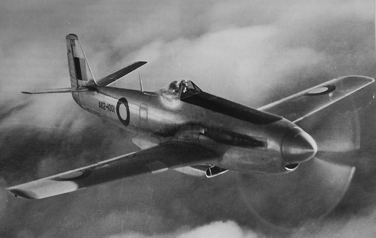
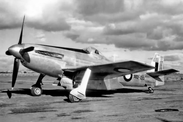
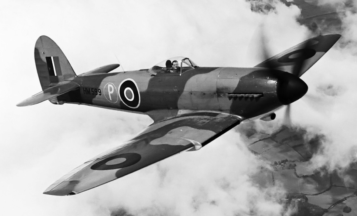
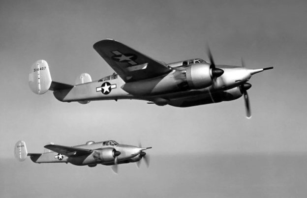
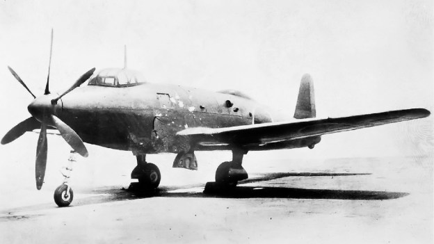
The impressive Commonwealth Aircraft Corporation CA-15 on a test flight. Note the patches on the wings that replaced the gun ports for the .50 cal machine guns.
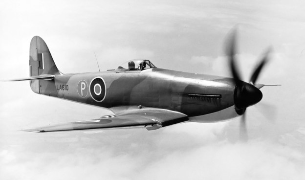
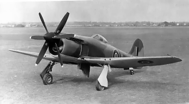
The preliminary design of the CAC CA-15 incorporated a Pratt & Whitney R-2800 engine, and the aircraft somewhat resembled a cross between a Boomerang and a Focke-Wulf Fw 190A. As the design was developed, the CA-15 changed to resemble a Hawker Tempest II with squared-off wings and tail, but with a General Electric (GE) C turbosupercharger installed in the rear fuselage, similar to the Republic P-47 Thunderbolt.
By mid-1943, a redesign was needed because the proposed power plant, the 2,000 hp (1,491 kW) R-2800-21, was not available. CAC selected the 2,200 hp (1,641 kW) R-2800-10W with a two-stage, two-speed supercharger as the new engine. With the engine change, the turbosupercharger was deleted, and a water-cooled intercooler was added in a large fairing under the engine. A geared cooling fan would help draw air in through the tight-fitting cowling. By December 1943, the R-2800-10W-powered CA-15 was estimated to have a maximum speed of 365 mph (587 km/h) at sea level, 436 mph (702 km/h) at 25,000 ft (7,620 m), and an initial climb rate of 4,200 fpm (21.3 m/s).

The Pratt & Whitney R-2800-21-powered CA-15, with cutaway to show the fuselage fuel tank. The turbosupercharger installation in the rear fuselage is not visible. In this early 1943 drawing, the CA-15 has a passing resemblance to the Hawker Tempest II.
The switch to the R-2800-10W engine also shifted the CA-15’s area of maximum performance from high altitude to low/medium altitude. At the time, CAC had obtained a license to produce the North American P-51D Mustang as the CA-17 and CA-18; CA-17s would be assembled from parts, and CA-18s would be CAC-produced aircraft. Lawrence Wackett, CAC’s General Manager, envisioned the CA-17/CA-18 filling the high altitude fighter role and the CA-15 covering low and mid altitudes. From mid-1943, CAC was focused on CA-17 assembly and CA-18 production, and progress on the CA-15 slowed as a result.
With many components for the prototype CA-15 under construction, CAC was disappointed to learn in May 1944 that the R-2800-10W was no longer in production. CAC found a suitable replacement in the form of the 2,800 hp (2,088 kW) R-2800-57. With this engine change, the CA-15 was back to incorporating a turbosupercharger—now a GE CH-5 housed in a deeper fairing under the engine. The R-2800-57-powered CA-15 was estimated to have a maximum speed of 400 mph (644 km/h) at sea level, 480 mph (772 km/h) at 28,000 ft (8,534 m), and an initial climb rate of 5,700 fpm (29.0 m/s).

A mid-1944 drawing of the CA-15 powered by a R-2800-57 engine. While the top view of the aircraft has not changed much, the bulky fairing under the engine has been added to house the intercooler and turbosupercharger.
By August 1944, the CA-15 prototype was around 50 percent complete. It was at this time that CAC was informed that supplies of the R-2800-57 could not be guaranteed. CAC again looked for an engine suitable for the CA-15 fighter. CAC found a new engine in the Griffon 125, then being developed by Rolls-Royce (R-R). The water-cooled Griffon 125 had a two-stage, three-speed supercharger and turned a single rotation propeller. The engine was capable of producing 2,440 hp (1,820 kW). A redesign of the CA-15 cowling was completed, and a scoop to house radiators for the engine coolant and oil was incorporated under the aircraft. With these changes, the CA-15 resembled a P-51D Mustang, but the resemblance was coincidental. The Griffon 125-powered CA-15 was estimated to have a maximum speed of 405 mph (652 km/h) at sea level, 467 mph (752 km/h) at 18,000 ft (5,487 m), and 495 mph (797 km/h) at 26,500 ft (8,077 m). The initial climb rate dropped slightly to 5,500 fpm (27.9 m/s).
Unfortunately, the Australian War Cabinet cancelled the CA-15 in September 1944. However, CAC continued work on the CA-15 at a reduced pace while it worked with the War Cabinet to reinstate the program. This was done in December, pending the approval of the Aircraft Advisory Committee, which followed in February 1945.
Work on the CA-15 now continued at a quicker pace, but engine issues surfaced again. R-R would not be able to provide a Griffon 125 until late 1945 at the earliest (but probably later). The CA-15 was ready for its engine, and CAC did not want to wait. As a substitute, two 2,035 hp (1,517 kW) Griffon 61s were loaned to CAC, the first being shipped in April 1945. The Griffon 61 had a two-stage, two-speed supercharger. As the CA-15 neared completion in December 1945, R-R informed CAC that the Griffon 125 would not be produced. The CA-15 used the Griffon 61 as its final engine, and the aircraft was completed in early 1946.
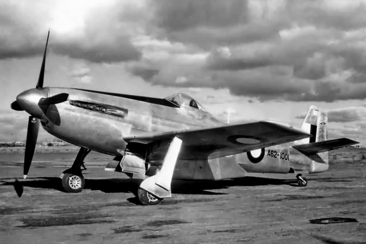
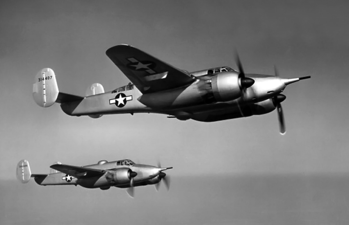
The completed CA-15 with its Griffon 61 engine bore a striking resemblance to the P-51D Mustang. However, the aircraft’s general layout changed little from the early 1943 drawing completed before CAC obtained a license for P-51 (CA-17/CA-18) production. Note the recessed engine exhaust stacks for improved aerodynamics.
The CA-15 was an all-metal aircraft of stressed-skin construction. The flaps and fully retractable gear were hydraulically operated. Various offensive armament combinations were considered, including four 20 mm cannons with 140 rpg, but six .50 cal machines guns were ultimately fitted with 250 rpg (various sources, including CAC documents, list 260, 280, or 290 rpg). The guns were not installed until a few months after the aircraft’s first flight. Underwing provisions existed for two 1,000 lb (454 kg) bombs or two 120 gal (100 imp gal / 454 L) drop tanks or 10 rockets.
In its final form, the CA-15 had a 36 ft (11 m) wingspan and was 36 ft 3 in (11 m) long. The aircraft’s internal fuel capacity was 312 gal (260 imp gal / 1,182 L), and it had a maximum range of 2,540 mi (4,088 km) with two drop tanks. The CA-15 weighed 7,540 lb (3,420 kg) empty, 10,764 lb (4,882 kg) with a normal load, and 12,340 lb (5,597 kg) at maximum overload. The Griffon 61-powered CA-15 had a maximum speed of 368 mph (592 km/h) at sea level, 448 mph (721 km/h) at 26,400 ft (8,047 m), and 432 mph (695 km/h) at 32,000 ft (9,754 m). The aircraft’s initial climb rate was 4,900 fpm (24.9 m/s), and it had a ceiling of 39,900 ft (12,162 m). The Griffon engine turned a 12 ft 6 in (3.81 m) diameter Rotol four-blade, wooden, constant-speed propeller. Initially, a 12 ft 1 in (3.68 m) propeller was used, the result of a damaged tip necessitating the blades being cut down. But a full-size propeller was fitted later during the flight test program.

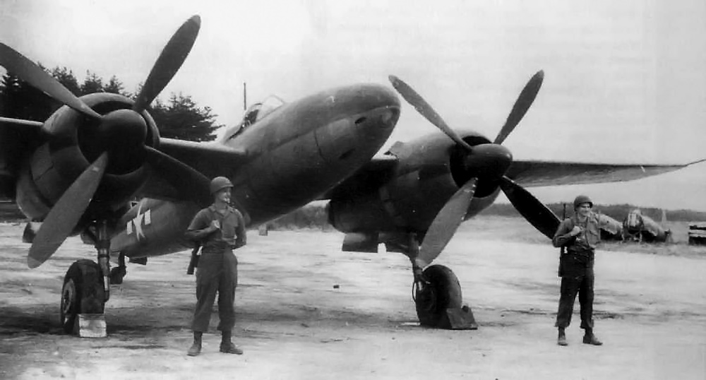
This photo of the CA-15 illustrates the tailplane’s 10 degrees of dihedral and the relatively good view the pilot had over the nose of the aircraft.
Assigned serial number A62-1001, the CA-15 began taxi tests in February 1946. After a few modifications, the aircraft first flew on 4 March 1946 with Jim Schofield at the controls. The initial test flights went well, although the ailerons were noted as being heavy. Aileron control was improved, and numerous other refinements were made. Throughout the test flights, the CA-15 proved itself as an easy to fly aircraft with excellent performance and very good visibility.
After 16.5 hours of flying time, the CA-15 was handed over to the Royal Australian Air Force (RAAF) Aircraft Performance Unit (APU) No. 1 on 2 July 1946 for further flight testing. While at APU No. 1, the landing gear struts were over-pressurized, causing the CA-15 to bounce badly during taxi tests. The hopping action of the aircraft earned it the unofficial nickname “Kangaroo,” which has lasted over the years. Unfortunately, on 10 December 1946, a test gauge failed and resulted in the loss of all hydraulics. With no flaps and the unlocked gear partially extended, Flt. Lt. Lee Archer was forced to make an emergency landing that damaged the aircraft’s scoop and destroyed the wooden propeller. The failed gauge should have been removed before the aircraft was handed over to the RAAF. At the time, the CA-15 had 43.25 flying hours, and the damage was not too severe. However, with the war over and jets coming into service, there was no possibility of the CA-15 going into production. As a result, repairs to the one-off prototype were slow, after finally being approved in April 1947.

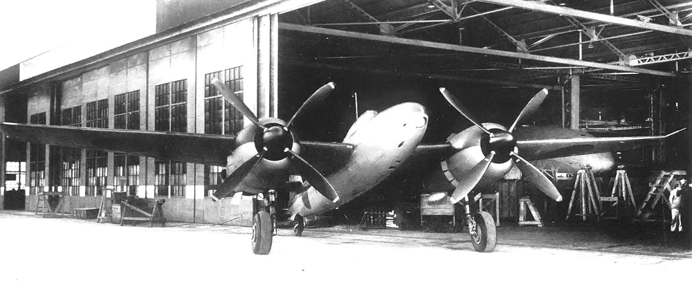
The CA-15 after a test flight. Note the scoop’s partially open cooling air exit flap. The aircraft in the background are most likely CAC-assembled CA-17s (P-51Ds), as the first CA-18 was not completed until 1947 (after the CA-15 was damaged).
CAC had repaired the CA-15’s airframe by October 1947, and the aircraft awaited a new propeller and radiator, which were the responsibility of the RAAF. The radiator was ready by February 1948, and the propeller followed in March. The CA-15 was returned to APU No. 1 on 19 May 1948. Later that month, the CA-15 grabbed headlines by achieving 502 mph (808 km/h) in a test flight over Melbourne, Victoria, Australia on 25 May 1948. This speed was recorded after Flt. Lt. Archer had leveled off at 5,000 ft (1,524 m) following a modest dive from 9,000 ft (2,743 m).
By February 1950, R-R wanted the two Griffon 61 engines back. In addition, there was no inventory of spare parts or any practical reason to continue flight testing of the CA-15. The engine was removed, and the CA-15 was scrapped, bringing an end to the highest performance aircraft ever designed and built in Australia.

The CA-15 “Kangaroo” was a powerful fighter with performance rivaling that of the best piston-powered aircraft. Sadly, it was built too late for action in World War II and at a time when jet aircraft were the undeniable future.
Sources:
– Wirraway, Boomerang & CA-15 in Australian Service by Stewart Wilson (1991)
– Wirraway to Hornet by Brian L Hill (1998)
– “Commonwealth CA-15: The ‘Kangaroo’ Fighter” by David Donald Wings of Fame Volume 4 (1996)
– R-2800: Pratt & Whitney’s Dependable Masterpiece by Graham White (2001)


 75 mm cannon")
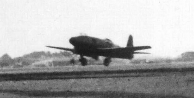
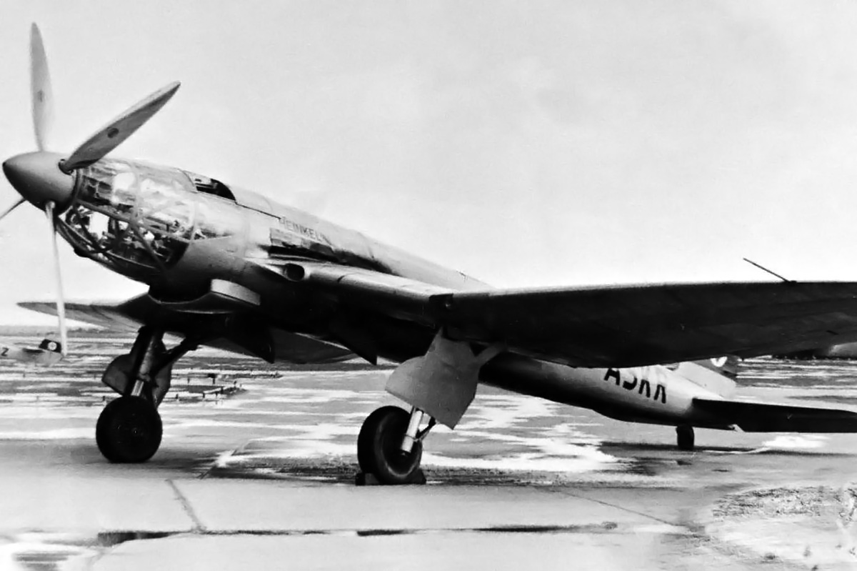
![The standard image of the Yokosuka R2Y1 Keiun. Speculation suggests the first scoop on the side of the aircraft provided cooling air for the engine's internal exhaust baffling, the second, larger scoop provided induction air for the normally aspirated Aichi [Ha-70] engine installed in the prototype, and the final two ports were for the engine's exhaust.](https://oldmachinepress.com/wp-content/uploads/2012/12/yokosuka-r2y1-keiun.jpg)