Yak-3 VK-108 front

Yakovlev Yak-3 VK-108 Fighter

By William Pearce

In 1944, Yakovlev sought to achieve higher performance from its Yak-3 fighter by installing a Klimov VK-108* engine. The standard Yak-3 was originally designated Yak-1M and designed in 1942 as a lightweight Yak-1. When this new aircraft entered production in 1943, it was redesignated Yak-3, taking the designation used for an earlier fighter prototype (the I-30) that did not enter production. Thus, Yak-3 production followed that of the Yak-7 and Yak-9 fighters.

Yak-3 VK-108 front

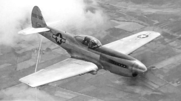
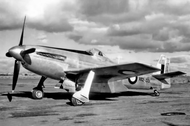
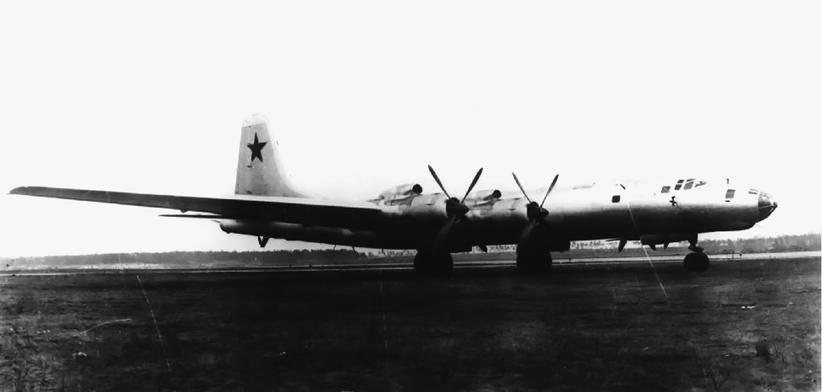
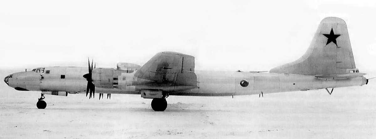
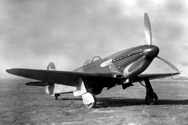
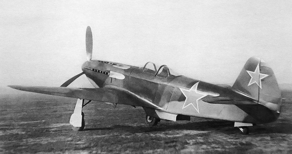
The Yak-3 VK-108 built in the closing days of World War II was the fastest Soviet piston-powered aircraft. Note the heat-resistant panels behind the exhaust stacks and the inlet for the supercharger under the engine. The upper row of exhaust stacks can just be seen.

The Yak-3 was a maneuverable fighter that incorporated everything the Yakovlev team had learned by producing its previous fighter aircraft. The fuselage was of metal construction and covered by duralumin from the cockpit forward, with plywood covering the rear fuselage. The aircraft’s wings had duralumin spars and wooden ribs and stringers. The wings were skinned with plywood that was covered with doped fabric. The Yak-3’s control surfaces consisted of a duralumin frame covered with fabric. The standard Yak 3 was powered by a VK-105PF2 engine producing 1,290 hp (962 kW) for takeoff and 1,240 hp (925 kW) at 6,890 ft (2,100 m) altitude.

The VK-105 engine can trace its origin back to the 750 hp (559 kW) M-100 engine of 1935, which was a licensed-built Hispano-Suiza 12Ybrs. However, many changes had been implemented by the time VK-105 production began in 1939. For example, the M-100 had a single-stage, single-speed supercharger, a 5.91 in (150 mm) bore, and two valves per cylinder. The VK-105 had a single-stage, two-speed supercharger, a 5.83 in (148 mm) bore, and three valves per cylinder.

Constructed under the supervision of lead designer Vladimir Klimov, the VK-105 was a liquid-cooled, V-12 engine with provisions for firing a cannon through the propeller hub. With its 5.83 in (148 mm) bore and 6.69 in (170 mm) stroke, the engine had a total displacement of 2,142 cu in (35.1 L). Each cylinder bank had a single overhead camshaft that actuated the two intake valves and single exhaust valve. The engine’s intake and exhaust ports were located on the outer sides of the engine. The intake manifold for each cylinder bank incorporated three carburetors. The VK-105 had a compression ratio of 7.1 to 1.

Yak-3 VK-108 3-view

This three-view drawing of the Yak-3 VK-108 shows that even with the cockpit moved aft 15.75 in (.40 m), the aircraft was very similar to a standard VK-105-powered Yak-3.

The ideal standard production Yak-3 had a top speed of 404 mph (650 km/h) at 14,108 ft (4,300 m) and 354 mph (570 km/h) at sea level. The aircraft could climb to 16,404 ft (5,000 m) in 4.2 minutes—averaging 3,906 fpm (19.8 m/s). The Yak-3 had an empty weight of 4,641 lb (2,105 kg) and a loaded weight of 5,864 lb (2,660 kg). The aircraft had a 20 mm cannon that fired through the propeller hub and two 12.7 mm machine guns mounted above the engine (the post-war Yak-3P was fitted with three 20 mm cannons).

It was on the standard Yak-3 platform that a VK-108 engine was substituted to create an aircraft of much higher performance. The VK-108 engine was a further evolution of the basic M-100 design, but by this time in its design history, the VK-108 had little in common with the original M-100 engine. The VK-108 was closely related to the VK-107 engine from which it was directly derived.

With the exception of the VK-107 engine, the VK-108 differed from previous Klimov engines by having new induction and exhaust systems, a new valve train with two intake and two exhaust valves per cylinder, strengthened components for increased rpm and power, an improved gear reduction, and increased boost via a redesigned supercharger drive. The VK-108 retained the 5.83 in (148 mm) bore, 6.69 in (170 mm) stroke, and 2,142 cu in (35.1 L) total displacement of previous Klimov engines.

Klimov VK-107A engine

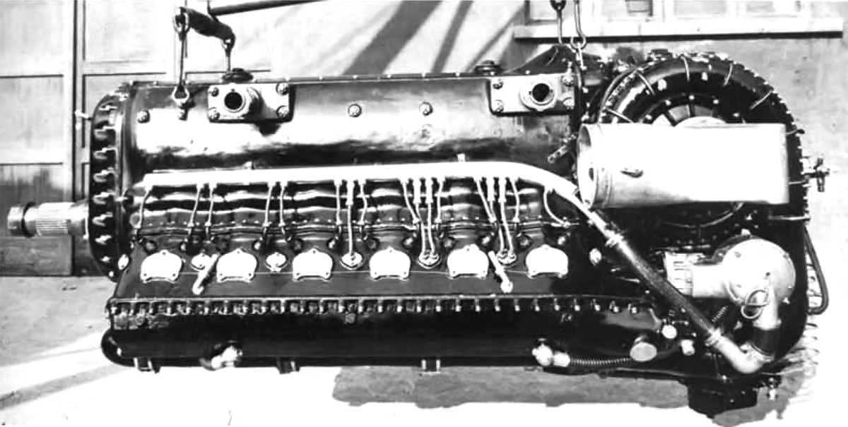
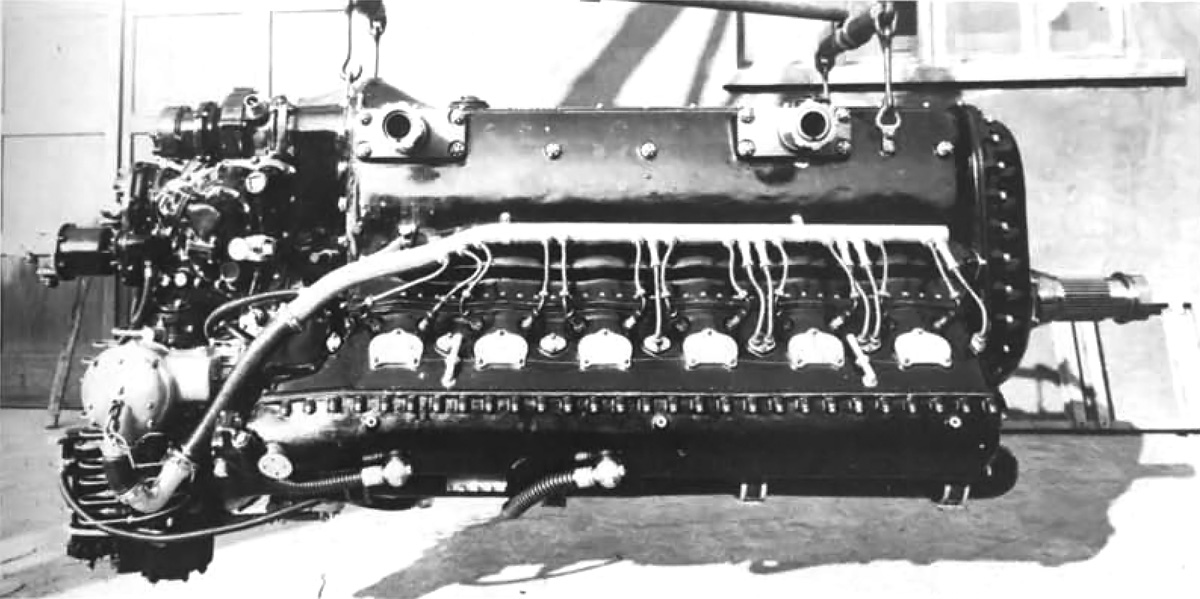
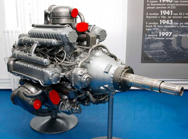
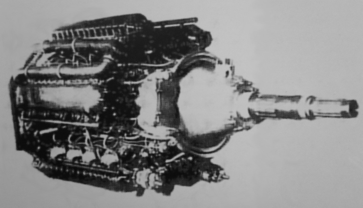
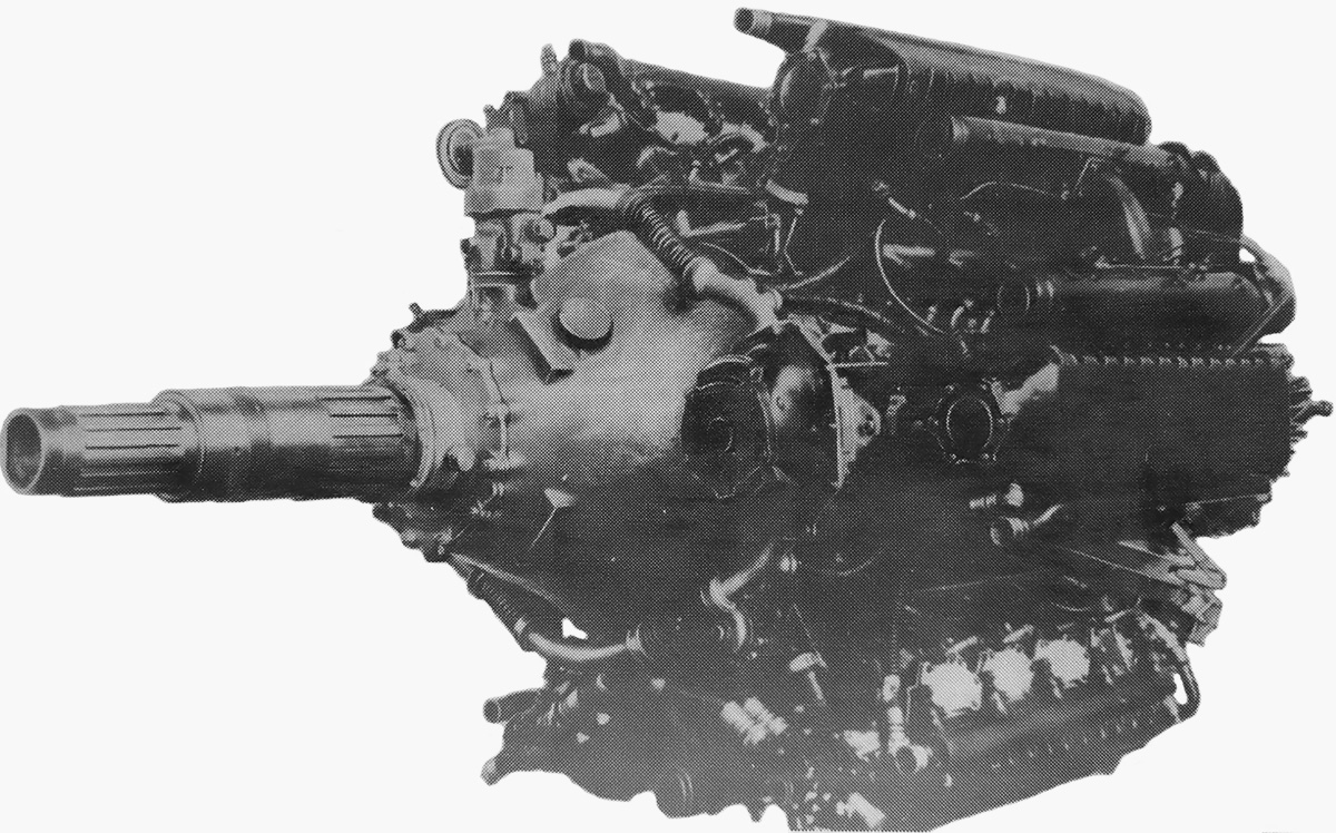
Pictures of a Klimov VK-108 engine are hard to come by. Seen here is a VK-107A engine which was very similar to the VK-108. Note the silver induction manifold along the outer side of the engine. The yellow linkages are for the three carburetors. The remaining four intake runners provide air only into the cylinders. The exhaust manifolds in the Vee of the engine are missing; the VK-107 used six-into-one manifolds while the VK-108 used individual exhaust stacks. (Mike1979 Russia image via Wikimedia Commons)

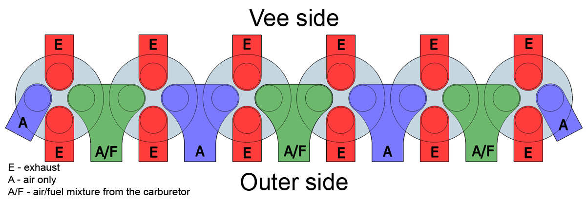
The most unusual features of the VK-108 engine were its intake and exhaust systems and the function of its four valves per cylinder. Pressurized air from the single-stage, two-speed supercharger flowed through an intake manifold located on the outer side of each cylinder bank. Each intake manifold had seven intake runners that led to the cylinder head. Four of the runners provided air only; the remaining three runners had individual carburetors to supply the air/fuel mixture to the cylinders. The first runner supplied just air to the first cylinder. The second runner provided the air/fuel mixture to the first and second cylinders. The third runner supplied just air to the second and third cylinders. The fourth runner provided the air/fuel mixture to the third and fourth cylinders. The fifth runner supplied just air to the fourth and fifth cylinders. The sixth runner provided the air/fuel mixture to the fifth and sixth cylinders. The seventh runner supplied just air to the sixth cylinder. So each carburetor supplied air/fuel for two cylinders; the engine had a total of six carburetors.

The two intake valves were positioned in tandem on the cylinder’s centerline. One intake valve in each cylinder opened to let supercharged air into the cylinder while the other intake valve opened to bring in the air/fuel mixture from a carburetor. The air intake valve opened 65 degrees before and closed after the air/fuel intake valve. This allowed the supercharged air to scavenge the cylinder and also aid in its cooling.

One exhaust valve was positioned on the outer side of the engine, and the other exhaust valve was on the Vee side. This configuration meant that there were separate exhaust ports on each side of the cylinder head. The VK-108 engine had one row of six exhaust stacks on the outer side of the cylinder bank and one row of exhaust stacks on the Vee side of the cylinder bank. The complete engine had four rows of six exhaust stacks.

Klimov VK-108 valve arrangement

Basic drawing of the Klimov VK-108 valve arrangement. A single overhead camshaft acted directly on the intake valves and actuated the exhaust valves via a follower.

A single overhead camshaft was used with three lobes for each cylinder. The center lobe acted on a follower that actuated both exhaust valves. One of the other lobes actuated the fresh air valve, and the last lobe actuated the air/fuel mixture valve. This arrangement allowed for the completely different valve timing and duration of the two intake valves.

The VK-108 was cleared for up to 8.5 psi (0.6 bar) of boost and had a compression ratio of 6.75 to 1. The engine produced 1,850 hp (1,380 kW) at 3,200 rpm for takeoff, 1,650 hp (1,230 kW) at 4,921 ft (1,500 m), and 1500 hp (1,119 kW) at 14,764 ft (4,500 m). The VK-108 weighed 1,731 lb (785 kg).

The installation of the VK-108 engine necessitated some changes of the Yak-3 airframe. Built under the supervision of A. N. Kanookov, the Yak-3 VK-108 had a new radiator, oil cooler, and propeller installed. A new cowling was constructed to accommodate the two additional rows of exhaust stacks. Heat-resistant panels were added behind each of the four rows of exhaust stacks. The cowling also omitted the ports for the two machine guns which were deleted from the Yak-3 VK-108. The supercharger air inlet was relocated under the engine, and the aircraft’s ailerons were skinned in duralumin rather than fabric. Because of the heavier engine, the cockpit was moved 15.75 in (.40 m) aft to keep the aircraft’s center of gravity within limits.

The VK-108-powered Yak-3’s first flight was on 19 December 1944 with Viktor L. Rastorgooyev at the controls. The aircraft had a wingspan of 30 ft 2 in (9.2 m), a length of 28 ft 1 in (8.55 m), an empty weight of 5,251 lb (2,382 kg), and a loaded weight of 6,385 lb (2,896 kg). With no armament and a light fuel load, the Yak-3 VK-108 achieved a top speed of 463 mph (745 km/h) at 20,636 ft (6,290 m), making it the fastest piston-powered Soviet aircraft. The aircraft also exhibited a phenomenal climb rate, reaching 16,404 ft (5,000 m) in 3.5 minutes—averaging 4,687 fpm (23.8 m/s). The Yak-3 VK-108 had a service ceiling of 34,121 ft (10,400 m).

Yak-3 VK-108 rear

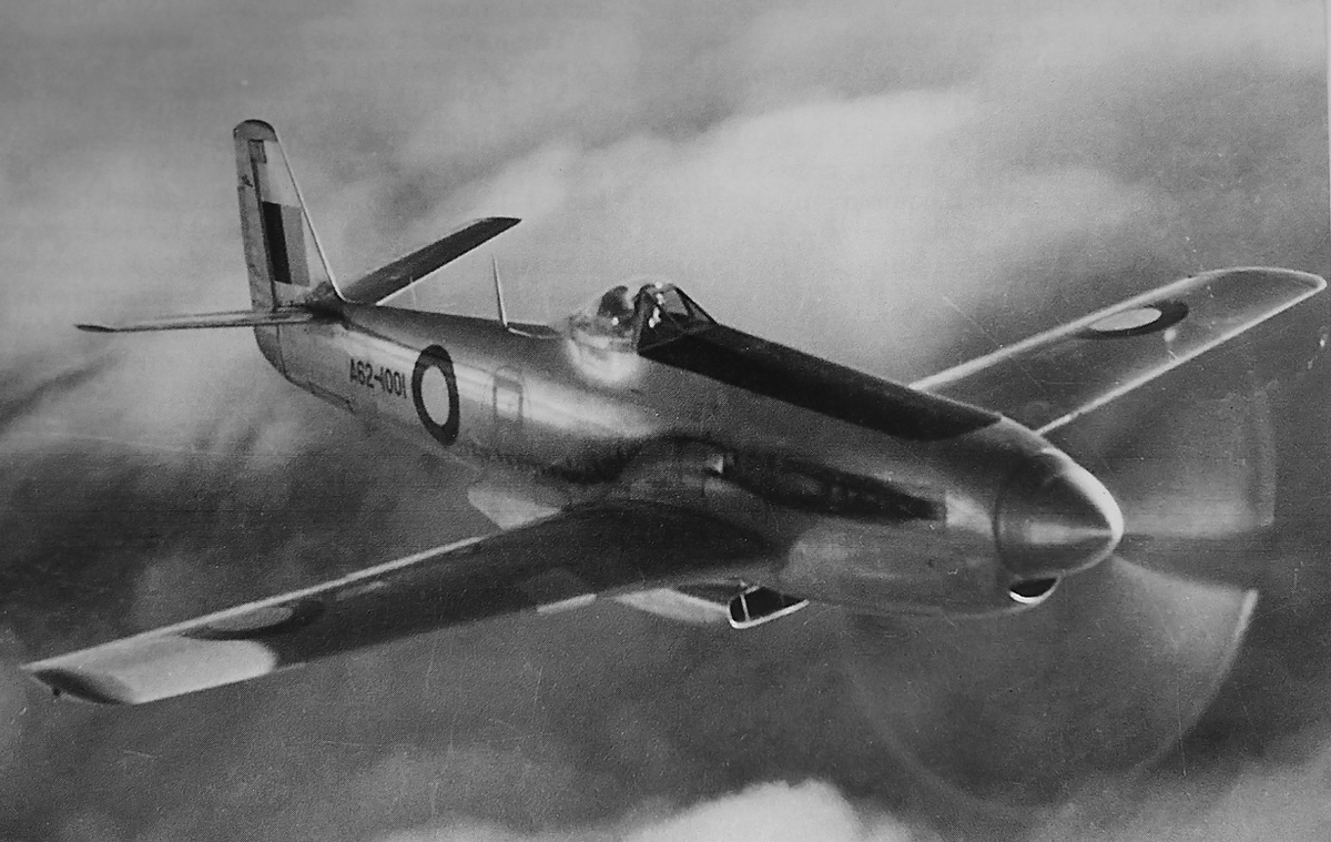
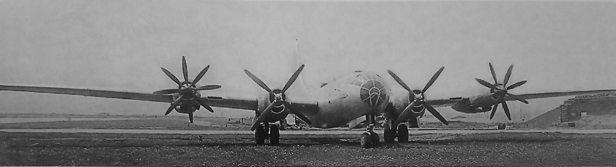
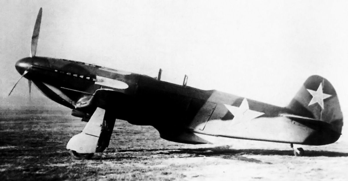
The upper exhaust stacks are well illustrated in this rear view of the Yak-3 VK-108. The aircraft had excellent performance, but the engine was not reliable.

Although the Yak-3 VK-108’s performance was very good, fight testing the aircraft was difficult because of engine issues. The VK-108’s high rpm and boost resulted in constant overheating problems. Vibration issues and excessive smoke were also encountered. The problems were so severe that flight testing was halted on 8 March 1945, with the aircraft only accumulating 1 hour and 17 minutes of flight time.

A second VK-108-powered Yak-3 was built in late 1945 under the supervision of V. G. Grigor’yev. This aircraft was reportedly armed with a 20 mm cannon that fired through the propeller hub and an additional 20 mm cannon mounted above the engine and offset to the left—each gun had 120 rounds of ammunition. A new radiator with additional surface area was installed to prevent overheating issues. However, engine trouble persisted. Despite its excellent performance, the Yak-3 VK-108 project was abandoned in favor of more reliable piston aircraft and jets.

*The Soviet Union changed some aircraft engine designations from starting with an “M” to starting with the designer’s initials. In 1944, the M-105 engine became the VK-105; the M-107 became the VK-107; and the M-108 became the VK-108—VK standing for Vladimir Klimov, the engine’s lead designer. The VK designation was used throughout this article for simplicity.

Yak-3 VK-108 side

By 1945, it was clear that future fighter aircraft would be jet-powered, and there was no need to continue the development of the VK-108 engine.

Sources:
Yakovlev Fighters of World War II by Yefim Gordon, Sergey and Dmitriy Komissarov (2015)
Russian Piston Aero Engines by Vladimir Kotelnikov (2005)
Hispano Suiza in Aeronautics by Manuel Lage (2004)
Yakovlev Aircraft since 1924 by Bill Gunston and Yefim Gordon (1997)
Yakovlev Piston-Engined Fighters by Yefim Gordon and Dmitriy Khazanov (2002)
http://www.airpages.ru/mt/m107_klimov.shtml

Reggiane Re 103 left side 1943

Reggiane Re 101 to Re 105 Aircraft Engines

By William Pearce

In 1936, the Italian aircraft manufacturer Officine Meccaniche Reggiane (Reggiane) branched out to produce aircraft engines. Initially, Reggiane produced Piaggio and FIAT engines under license, but it was not long before the company began to develop its own aircraft engines. As world events unfolded in the 1940s, only one model of Reggiane’s aircraft engines was built, and it did not proceed beyond the testing phase.

Reggiane Re 103 April 1942

The Reggiane Re 103 RC50 I engine in April 1942 before spark plug wires and fuel lines were added. Note the two spark plugs per cylinder.

Reggiane’s first aircraft engine design was the Re 101 RC50 I*. The “R” in the engine’s designation meant that it had gear reduction (Riduttore de giri); the “C” meant that it was supercharged (Compressore); the “50” stood for the engine’s critical altitude in hectometers (as in 5,000 meters), and the “I” meant the engine was inverted (Invertita). Occasionally, a letter was added to designate the engine’s configuration, as in “L” for inline (Linea) appearing as Re L 101 RC50. Proposed in the late 1930s, the Re 101 RC50 I was an inverted, liquid-cooled V-12 of 1,635 cu in (26.8L). Although its bore and stroke have not been found, they were probably around 5.51 in (140 mm) and 5.71 in (145 mm) respectively. The engine produced 1,200 hp (895 kW) for takeoff, 1,100 hp (820 kW) at 16,400 ft (5,000 m), and weighed 1,477 lb (670 kg). The Re 101 RC50 I engine possessed similar specifications to the Rolls-Royce Merlin but did not proceeded beyond its initial design.

Reggiane’s next engine, also designed in the late 1930s, was the Re 102 RC50 I. The engine was an inverted W-18 (sometimes called an M-18, “M” being an inverted “W”), with three banks of six cylinders. The Re 102 RC50 I displaced 2,075 cu in (34 L), produced 1,550 hp (1,156 kW) for takeoff and 1,350 hp (1,007 kW) at 16,400 ft (5,000 m), and weighed 1,676 lb (760 kg). The engine’s bore and stroke have not been found, but were probably around 5.28 in (134 mm). The Re 102 RC50 I did not proceeded beyond the design phase.

Reggiane Re 103 3-view

Undated three-view drawing of the Re 103 RC50 I engine. Note that it is listed as “18 Cilindri a M,” referring to its M-18 engine configuration.

In 1940, Reggiane focused on their next engine design, the Re 103. Like the Re 102 RC50 I, the Re 103 was an inverted W-18. However, with a bore of 5.51 in (140 mm), a stroke of 5.67 in (144 mm), and a total displacement of 2,435 cu in (39.9 L), the Re 103 was a larger engine than the Re 102 RC50 I. The Re 103 had a 6 to 1 compression ratio and a .511 propeller gear reduction. The engine was 91 in (2.33 m) long, 38 in (.97 m) wide, 36 in (.91 m) tall, and weighed 1,874 lb (850 kg). The Re 103 RC50 I was a candidate for the Reggiane RE 2005 fighter, along with a few other projects.

Although an independent design, the Reggiane Re 103 was in some ways similar to the Daimler-Benz DB 600 series engines. Both the DB 600 series engines and the Re 103 were inverted, had the supercharger impeller mounted parallel to the crankshaft on the upper left side of the engine, and featured fuel injection controlled by a module at the rear of the engine. Reggiane did have access to DB engines because licensed-built versions of the DB 601 (Alfa Romeo RA 1000 RC41 I) and DB 605 (FIAT RA 1050 RC58 I) were used in the RE 2001 and RE 2005 fighters respectively.

Reggiane Re 103 front-back 1943

Front and rear of the Re 103 RC50 I engine. In the front view, note how the intake manifold feeds the individual cylinder banks. In the rear image, note the fuel injector distribution pump and the various fuel lines leading to each cylinder.

Air from the Re 103’s supercharger flowed through two manifolds positioned in between the engine’s cylinder banks. The left manifold supplied air to the left and center cylinder banks, while the right manifold provided air to the right cylinder bank. The manifolds met at the front of the engine, forming a loop. To keep frontal area to a minimum, the cylinder banks were positioned 40 degrees apart. Each cylinder had two intake and two exhaust valves. The valves were actuated by a single overhead camshaft. Each of the three camshafts (one for each cylinder bank) was driven by a vertical shaft at the rear of the engine. Also driven from the rear of the engine were the two magnetos that fired two spark plugs for each cylinder. The spark plugs were positioned on the outer side of the left and right cylinder banks and on the left side of the center cylinder bank. The fuel injectors were positioned on the inner side of the left and right cylinder banks and on the right side of the center cylinder bank.

Two versions of the Re 103 were initially proposed. The Re 103 RC50 I had a three-speed supercharger and was intended for fighter aircraft, while the Re 103 RC40 I had a two-speed supercharger and was intended for bombers. The supercharger was designed to automatically change speed according to the aircraft’s altitude. The Re 103 RC50 I used 100 octane fuel and produced 1,740 hp (1,298 kW) for takeoff at 2,840 rpm with 7.2 psi (.49 bar) boost and 1,600 hp (1,193 kW) at 16,400 ft (5,000 m) with 4.6 psi (.32 bar) boost. The Re 103 RC40 I used 87 octane fuel and produced 1,700 hp (1,298 kW) for takeoff at 2,840 rpm with 6.4 psi (.44 bar) boost and 1,500 hp (1,119 kW) at 13,123 ft (4,000 m) with 3.4 psi (.24 bar) boost.

Reggiane Re 103 left side 1943

Left side of the Re 103 RC50 I engine displaying the supercharger mounted in a very similar manner as on the DB 600 series engines. Of course, no engine mounted cannon could be used on the W-18 Re 103 engine.

Three Reggiane Re 103 RC50 I engines were ordered by the Ministero dell’Aeronautica (Air Ministry) for the Regia Aeronautica (Royal Italian Air Force). A prototype Re 103 RC50 I was built by April 1942 and ran later that year. Development of the Re 103 inspired two additional and very similar engines, the Re 103 RC57 I and the Re 105 RC100 I. Both of these engines had the same configuration and displacement as the Re 103. The Re 103 RC57 I weighed 2,061 (935 kg), and its supercharger was optimized for 18,700 ft (5,700 m), where the engine produced 1,405 hp (1,048 kW). No orders were placed for the Re 103 RC57 I.

The Re 105 RC100 I engine had a two-stage supercharger and was optimized for 32,808 ft (10,000 m), at which altitude the engine produced 1,310 hp (977 kW). The two-stage supercharger was essentially made up of two separate superchargers. The first stage was located on the right side of the engine and mirrored the second stage, which was located in the original Re 103 supercharger position on the left side of the engine. Air flowed through a tube from the first stage, around the back of the engine, and into the inlet of the second stage. The Re 105 RC100 I weighed 1,984 lb (900 kg). Three Re 105 RC100 I engines were ordered in 1943.

Reggiane Re 103 right side 1943

The complete Reggiane Re 103 RC50 I engine in October 1943. The 18-cylinder engine produced 1,740 hp (1,298 kW) for takeoff.

Three other engine designs were studied in 1941 while the Re 103 was being built. The Re 104 RC38 was the first, and it was a V-12 that produced 1,100 hp (820 kW) at sea level. The engine was derived from the Isotta Fraschini Asso L.121 RC40 but with a two-speed supercharger. The Re 104 RC38 had a 5.75 in (140 mm) bore and 5.67 in (160 mm) stroke. Its total displacement was 1,765 cu in (28.9 L), and the engine was intended as a possible alternative to the DB 601. No examples were built.

The second design study was for a 24-cylinder engine using four Re 103 cylinder banks in a horizontal H configuration. This design allowed many parts to be interchangeable with the Re 103 engines. Reggiane’s H-24 engine produced 2,200 hp (1,621 kW) at 19,685 ft (6,000 m). If the 24-cylinder engine had the same bore and stroke as the Re 103, it would have had a displacement of 3,247 cu in (53.2 L). The last engine under study was a two-stroke diesel of unknown specifics. The H-24 and the diesel did not progress beyond the initial design.

Reggiane Re 105 RC100 and H-24

Top—rear and top views of the Re 105 RC100 engine. Note the two-stage supercharger arrangement. The outline around the front of the engine was for a proposed long gear reduction that added 6 in (.15 m) to the engine’s length. Bottom—front and side views of the H-24 engine. Note the crankshafts rotated clockwise (when viewed from the rear), and the propeller shaft rotated counterclockwise, just like the Re 103 and Re 105 engines.

At least two Re 103 engines were built, and most likely they were both Re 103 RC50 I engines, but development was slow. Construction had also begun on the Re 105 RC100 I. Italy’s surrender on 8 September 1943 brought an end to all of Reggiane’s engine programs. After the surrender, Reggiane’s northern factories were under German control and manufactured parts for the Daimler-Benz DB 605 and other engines. The Germans were not interested in the Re 103 or other Reggiane engines, and developmental activity was not continued.

*Italian aircraft engine naming convention varies by source. As an example, the punctuation, capitalization, and spacing of the Re 101 RC50 I designation can vary and still refer to the same engine, as in RE-101R.C.50 I or Re.L 101 R.C. 50 I.

Reggiane RE 2005

The Reggiane RE 2005 fighter was a potential candidate to be powered by the Re 103 engine. Only about 48 examples of the aircraft were built, and they were powered by the 1,475 hp (1,100 kW) FIAT RA 1050 RC58 I (licensed-built Daimler-Benz DB 605).

Sources:
I Reggiane dall’ A alla Z by Sergio Govi (1985)
– “I Motori Alle Reggiane” by Adriano and Paolo Riatti, Associazione Amici del Corni (March 2013)
The Caproni-Reggiane Fighters 1938-1945 by Piero Prato (1969)
https://it.wikipedia.org/wiki/Reggiane_RE_103
http://www.webalice.it/paolo.riatti/motori.html

Curtiss XP-40Q-2A flight

Curtiss XP-40Q Fighter

By William Pearce

Although not readily apparent at the time, Curtiss-Wright’s Airplane Division (Curtiss) was already in a state of decline at the start of World War II. The company’s final two truly successful aircraft, the P-40 Warhawk fighter and C-46 Commando transport, had already flown. While the Curtiss SB2C Helldiver carrier-based dive bomber would achieve some success toward the end of the war, its development was prolonged and plagued with issues, and the aircraft was never liked by its pilots and crews. Throughout the war years, Curtiss continually strove to develop world-beating aircraft but only managed to build one dead-end prototype after another. A brief glimmer of hope lay in the last model of the P-40, the P-40Q (Curtiss model 87X).

Curtiss XP-40Q-1

The Curtiss XP-40Q-1 (42-9987) with its standard canopy and sleek nose. Note the scoop for the engine air intake above the cowling.

XP-40Q development was initiated by 1943. The goal was to improve the P-40 to equal or surpass the performance of newer fighter aircraft. It was thought that the improved performance of the P-40Q would justify the aircraft entering production, and its similarities with P-40s then being produced would minimize tooling and production delays. In addition, there would be some part interchangeability with older P-40 aircraft, and current P-40 pilots and crews would be familiar with the new aircraft and its systems.

Three XP-40Q prototypes were built; their origins and histories have always been a point of disagreement between sources. All XP-40Qs were built up from other P-40 airframes. They all had only four .50-cal machine guns with 235 rpg. All of the XP-40Q aircraft were powered by two-stage supercharged Allison V-1710 engines and a four-blade propeller.

Curtiss XP-40Q-1 front

Another view of the XP-40Q-1. Note the radiators and oil coolers mounted in the wing center section.

The XP-40Q-1 was the first aircraft, and it was built in 1943 from a P-40K-10 (serial 42-9987) that had been damaged in a landing accident on 27 January 1943. The Q-1 was painted olive drab and had the standard P-40 wing and canopy. The nose of the aircraft was lengthened to accommodate the V-1710-101 (F27R) engine. At 3,200 rpm, the -101 engine produced 1,500 hp (1,119 kW) at 6,000 ft (1,829 m) and 1,325 hp (988 kW) for takeoff. The Q-1’s engine air intake was positioned above the cowling. The radiator and oil cooler were moved from the P-40’s iconic chin location to the wing center section, just below the fuselage (similar to the XP-40K). The XP-40Q-1 had a 37 ft 4 in (11.4 m) wingspan and was 35 ft 4 in long (10.8 m)—about 2 ft (.6 m) longer than a standard P-40.

The Q-1’s first flight reportedly occurred on 13 June 1943 from the Curtiss plant in Buffalo, New York. It is not clear if the aircraft suffered another accident, or if Curtiss was unhappy with its configuration and decided to modify it further. Regardless, by November 1943, the Q-1 had been modified and redesignated XP-40Q-2. The aircraft’s rear fuselage was cut down and a bubble canopy installed. Engine coolant radiators were positioned in the wings just outboard of the main gear. The oil cooler and engine air intake were relocated to the classic P-40 chin position, but the scoop was shallower and more elegant. The Q-2 retained the olive drab paint.

Curtiss XP-40Q-2

The Curtiss XP-40Q-2 (still 42-9987) after modification with a bubble canopy. The oil cooler and engine air intake have been relocated to the scoop under the engine. The coolant radiators have been moved outside of the main gear. The wings are still the standard P-40 wings, but they were later clipped by about one foot.

Still utilizing the -101 engine, the Q-2 was noted for having excellent visibility and handling. The aircraft had balanced controls and was very maneuverable, with a tight turn radius. Capt. Gustav Lundquist had evaluated the Q-2 and judged it to be the best P-40 he had flown; he recommended that further flight testing should be conducted. In December 1943, the Air Materiel Command recognized the XP-40Q-2’s performance and recommended that two additional prototypes be constructed.

Reportedly, the Q-2 was delivered to Eglin Field, Florida for testing in January 1944, but it was back at the Curtiss plant in Buffalo, New York in March for a series of flight tests. By this time, the Q-2 had its wingtips clipped about one foot each, and a V-1710-121 (F28R) engine was installed. The -121 produced 1,800 hp (1,342 kW) with water injection at 3,200 rpm up to 20,000 ft (6,096 m) and 1,425 hp (1,062 kW) for takeoff.

Curtiss XP-40Q-2A side

The XP-40Q-2A (42-45722) looking very much like the XP-40Q-2 but with clipped wings. This aircraft would change little throughout its existence.

A flight evaluation from April 1944 again noted the XP-40Q-2 as superior to all other P-40s and a very good aircraft overall. The XP-40Q-2 had a 35 ft 3 in (10.7 m) wingspan and was 35 ft 4 in (10.8 m) long. With full engine power at 3,000 rpm and water injection, the aircraft achieved 420 mph (676 km/h) at 15,000 ft (4,572 m) and had a maximum climb rate of 4,410 fpm (22.4 m/s) at 5,000 ft (1,524 m). At 3,200 rpm and with water injection, maximum speed was 422 mph (679 km/h) at 20,500 ft (6,248 m), and the climb rate increased by as much as 530 fpm (2.7 m/s) depending on altitude. However, the 3,200 rpm engine speed was only shown to offer an advantage between 12,000 and 33,000 ft (3,658 and 10,058 m). With just military power, the Q-2 recorded a speed of 407 mph (655 km/h) at 24,000 ft (7,315 m) and a climb rate of 3,210 fpm (16.3 m/s) at sea level. The aircraft could climb from sea level to 20,000 ft (6,096 m) in 4.8 minutes, 30,000 ft (9,144 m) in 8.9 minutes, and 39,000 ft (11,887 m) in 26.1 minutes. The Q-2’s service ceiling was 39,000 ft (11,887 m), and it had a gross weight of 9,000 lb (4,082 kg). The aircraft’s range was 700 miles (1,127 km).

The Q-2 was damaged when it nosed over after a test flight on 24 March 1944. The aircraft was repaired and then sent to Wright Field, Ohio in mid-1944. The aircraft was damaged again when it ground looped while landing on 31 July 1944. It is not clear if the aircraft was repaired or if the damage was too severe.

Curtiss XP-40Q-2A flight

This image of the XP-40Q-2A illustrates the clipped wings. Note the size of the bubble canopy and how to could be a bit smaller. The four .50-cal wing guns are easily seen. The XP-40Q was definitely a nice looking aircraft.

The next aircraft was the XP-40Q-2A. It was built from the initial P-40K-1 (serial 42-45722) that had been converted to the (unofficial) XP-40N. During the XP-40N conversion, the aircraft had a bubble canopy installed. This modification predated and served as the template for the bubble canopy that was installed on the Q-2.

The Q-2A was very similar to the final configuration of the Q-2—with a bubble canopy, clipped wings, and -121 engine. However, some modifications to the cockpit and canopy were made, and automatic radiator and oil cooler shutters were added. The Q-2A had a natural metal finish.

The Q-2A’s first flight occurred prior to the end of March 1944. The aircraft was plagued with engine trouble that resulted in a number of forced landings. The Q-2A spent most of its test time down for repairs. As a result, the Army Air Force (AAF) focused on the next aircraft, the Q-3, and loaned the Q-2A to Allison for engine tests. The Q-2A most likely had the same specifications and performance as the -121-powered Q-2.

The XP-40Q-3 was the last aircraft in the series. The Q-3 was built in early 1944 from a P-40N-25 (serial 43-24571) and was the only XP-40Q actually classified as such by the AAF. The aircraft was very similar to the XP-40Q-2A except for some refinements to the canopy and windscreen. The canopy was a bit smaller, and the flat windscreen was longer and more angled than the windscreen used on the preceding aircraft. Overall, the changes improved pilot visibility. The Q-3 had a -121 engine and a natural metal finish.

Curtiss XP-40Q-3 front

The last of the Curtiss P-40Qs: the XP-40Q-3 (43-24571). This aircraft later had anti-glare paint applied to the upper cowling, its serial number painted on the the tail, and “12” painted on the chin scoop. Note the radiator air inlets in the wings.

Delivered to AAF in April 1944, the Q-3 suffered an engine failure during an early test flight. The aircraft was moderately damaged in the subsequent forced landing. At this time, other aircraft with superior performance were available, and there was no AAF interest in repairing the Q-3 because there was no need for a P-40Q. It is doubtful that much performance testing was conducted on the Q-3, but the results should have been similar to those of the Q-2.

In March 1946, Allison still had the XP-40Q-2A (the second XP-40Q) when the AAF declared the aircraft as surplus. It is not clear if Allison purchased the aircraft and then later resold it or if it was sold as surplus directly from the AAF. Regardless, Joe Ziegler acquired the aircraft, and it was registered as NX300B. Given race number 82, the Q-2A was entered in the 1947 Thompson Trophy Race (run on 1 September 1947), but it did not qualify. Ziegler started the race anyway and was running in fourth place when the engine caught fire after just completing the 13th lap. Ziegler pulled up and off the course and bailed out of the Q-2A. Zeigler suffered a broken leg, and the Q-2A was destroyed.

Curtiss XP-40Q-3 side

This view of the XP-40Q-3 illustrates the revised canopy compared to the XP-40Q-2A. Note the oil cooler exit doors on the cowling just in front of the wing.

The story of the XP-40Q aircraft is a confusing one involving only three airframes but somewhere around eight designations and a number of different configurations. The P-40Q was one of the finest fighters Curtiss ever built, but the aircraft was two years or so too late. Its performance and capabilities were matched or exceeded by other aircraft already in service. Even if the P-40Q airframe had been ready two years earlier, the two-stage Allison engines would not have been ready, as they were still having developmental trouble in 1944. Sadly, the XP-40Q scenario was played out again and again as Curtiss tried to create another successful aircraft but only managed to produce aircraft that were ill-timed and outclassed.

Note: There is no indication that any of the XP-40Q aircraft used any type of a laminar flow wing. There is also no indication that any XP-40Q information was passed from Curtiss to North American Aviation (NAA) during the NA-73X’s (P-51’s) development. Not only are the two aircraft different in almost every way, there is no part of their separate developmental timelines that coincide. NAA did purchase some information from Curtiss at the request of the British government, but that information pertained to the XP-46 and arrived after the NA-73X was already designed.

Curtiss XP-40Q-2A Race 82

The XP-40Q-2A seen at Cleveland, Ohio for the Thompson Trophy Race in 1947. Other than some paint, including its registration and race number, the aircraft had changed little since its AAF days. It is truly unfortunate that the aircraft would soon be destroyed as a result of an engine fire.

Sources:
Curtiss Fighter Aircraft by Francis H. Dean and Dan Hagedorn (2007)
Vee is for Victory by Dan D. Whitney (1998)
U.S. Experimental & Prototype Aircraft Projects: Fighters 1939-1945 by Bill Norton (2008)
Memorandum Report on P-40Q Airplane, AAF No. 42-9987 by Capt. Gustav E. Lundquist (2 November 1943) via www.wwiiaircraftperformance.org (1.1 MB)
Flight Tests on the Curtiss XP-40Q-2, AAF No. 42-9987 by Lt Norman A. Krause (5 April 1944) via www.wwiiaircraftperformance.org (10.9 MB)

Wedell-Williams Model 45

Wedell-Williams Model 45 Racer

By William Pearce

In 1932, the Wedell-Williams Air Service Model 44 established itself as one of the premier air racers. The Model 44 was a fast, sleek monoplane with fixed gear. The aircraft was designed by Jimmie Wedell, an experienced pilot and air racer. The Weddell-Williams company was founded in 1929 when Jimmie Wedell and his brother Walter gained the financial backing of millionaire Harry Williams. Operating out of Patterson, Louisiana, Wedell-Williams Air Service was established to provide a wide range of aeronautical services that included constructing new aircraft, flight instruction, and passenger and mail service. The best way to prove one’s aircraft design abilities and gain publicity was to create a record breaking air racer—the Model 44 was exactly that. However, progress in aviation was swift, so it was in 1933 that Wedell began to design his next racer: the Model 45.

Wedell-Williams Model 45 side

The Model 45 followed the Wedell-Williams design concept that was so well executed in their Model 44 racer. It was a simple concept: a big engine in a sleek airframe resulting in a fast aircraft.

The Model 45 followed the same conventional layout as the Model 44, but the aircraft was further refined with a cantilever wing and retractable undercarriage. The Model 45 consisted of a welded chrome-molybdenum steel tube fuselage. The front and tail of the aircraft were skinned in aluminum. Fabric covered the rest of the fuselage, from in front of the cockpit back to the tail. The Model 45’s wing had a wooden spar; the rest of the structure was made from metal and skinned with aluminum. The main gear retracted inward to be fully enclosed within the wing. The aircraft’s tail skid retracted into the fuselage. Each side of the cockpit had a plexiglass panel that could slide up to fully enclose the pilot.

The Model 45 had a 26 ft 8.5 in (8.1 m) wingspan and was 24 ft long (7.3 m). The aircraft had a race weight of around 3,000 lb (1,360 kg). The Model 45 was intended to have a 14-cylinder Pratt & Whitney (P&W) R-1535 Twin Wasp radial engine of 825 hp (615 kW), and its top speed was anticipated to be over 300 mph (483 km/h). However, the R-1535 engine was not ready, so a nine-cylinder P&W R-985 Wasp Jr. engine of 535 hp (399 kW) was installed in its place.

Wedell-Williams Model 45 early

This photo of the Model 45 was taken shortly after the aircraft was built in Patterson, Louisiana in 1933. Note the smooth cowling covering the R-985 engine. Jimmie Wedell stands by the side of the aircraft.

Wedell took the Model 45 (registered as NR62Y) up for its first flight on 28 June 1933. The R-985 engine caused the aircraft to be underpowered and tail-heavy. Very little flight testing was accomplished because Wedell had entered the Model 45 in the Bendix Trophy Race, which was scheduled for 1 July. The 1933 race was run from New York to Los Angeles. Departing for New York, Wedell made it from Patterson, Louisiana to Atlanta, Georgia (about 500 miles / 805 km) before he turned back. Wedell decided the aircraft would not be competitive with its current engine. Instead, he flew a Model 44 (No. 44) and finished the race in second place, behind Roscoe Turner in his Wedell-Williams Model 44 (No. 2).

With the R-1535 still delayed, a nine-cylinder, 800 hp (597 kW) P&W R-1340 Wasp Sr. engine was installed on the Model 45 in place of the smaller engine. The R-1340 provided sufficient power for the aircraft and restored its proper balance. While the two engines used the same mounts, the R-1340 had a larger diameter than the R-985 and required a new cowling. The smooth cowling covering the R-985 engine was replaced by a larger cowling with bumps around its diameter to provide clearance for the engine’s rocker covers. The same engines were used in the Model 44, so the entire engine package (including cowling) could be swapped between the aircraft. An 8 ft 2 in (2.5 m) diameter, variable-pitch propeller was also installed.

Wedell-Williams Model 45 front

The Model 45 with its R-1340 engine installed. Note the bumps on the cowling that provided clearance for the engine’s rocker covers. The engines used in the Model 45 and Model 44 (No. 44) racer were interchangeable.

The Model 45 made its race debut at the Pan American Air Races held during the dedication of Shushan Airport (now New Orleans Lakefront Airport) in February 1934. Wedell flew the Model 45 to a new speed record over a 100 km (62 mi) course, averaging 264.703 mph (425.998 km/h), with the fastest lap over 266 mph (428 km/h). Wedell reported that he flew the distance at less than full power.

After the record run, Wedell-Williams Air Service began work to prepare their aircraft for the 1934 Bendix and Thompson Trophy Races, respectively scheduled for 31 August and 4 September. But disaster struck on 24 June 1934; Jimmie Wedell was killed when the de Havilland Gypsy Moth he was piloting crashed shortly after takeoff. Wedell was with a student pilot but had control of the aircraft. The student escaped with only minor injuries. The loss of head designer Jimmie Wedell was a major blow to Wedell-Williams Air Service, but the company continued to plan for the upcoming races.

Wedell-Williams Model 45 Jimmie

Jimmie Wedell stands by the Model 45. Note the doors for the retractable tail skid.

Experienced Wedell-Williams pilot John Worthen flew the Model 45 in the Bendix Trophy Race from Los Angles, California to Cleveland, Ohio. Worthen led the race, followed by Doug Davis flying Wedell-Williams Air Service’s other racer, a Model 44 (No. 44). Worthen, in the Model 45, had a comfortable lead when he became lost and overflew Cleveland by 100 miles (160 km). Worthen landed and refueled in Erie, Pennsylvania and then flew to Cleveland; he landed 36 minutes behind Davis. Had he not overflown Cleveland, Worthen and the Model 45 would have easily won the Bendix race; the trip to Erie added over 50 minutes to his total time. Even with the delay, the Model 45 had averaged 203.213 mph (327.040 km/h) in the Bendix Trophy Race.

In the Shell Speed Qualification heat (Group 3) for the Thompson Trophy Race, Worthen and the Model 45 placed third at 292.141 mph (470.156 km/h), coming in behind the Model 44 racers of Davis (No. 44) at 306.215 mph (492.805 km/h) and Roscoe Turner (No. 57) at 295.465 mph (475.505 km/h). In the Shell Speed Dash Unlimited race, Worthen and the Model 45 achieved 302.036 mph (486.080 km/h).

Wedell-Williams Model 45

The size and weight of the Wedell-Williams Model 45 was more suited for cross-country racing than pylon racing. It would have won the 1934 Bendix race had it not been for a navigation error. The Model 45 is barely an aviation footnote since it was flown fewer than two years and never won a major race.

The Wedell-Williams Air Service team decided that the Model 44 (No. 44) had the greatest potential for the Thompson Trophy Race. This decision was made because of some instability the Model 45 exhibited in the pylon turns—perhaps because the aircraft was not fully refined due to Wedell’s death. The team had been swapping the R-1340 and R-985 engines between racers for various events, and now the R-1340 engine was installed in the Model 44 for the Thompson Trophy Race. The Model 45 would not be competitive with the R-985 engine, and it was withdrawn from the race.

During the Thompson Trophy Race, Davis and the Model 44 were comfortably in the lead when he cut a pylon. He went back to circle the pylon when the aircraft either stalled or experienced a structural failure. The Model 44 smashed into the ground, killing Davis instantly. The shocked Wedell-Williams Air Service team disassembled the Model 45 and shipped it back to Paterson; it never flew again.

Wedell-Williams Air Service was never able recover because tragedies continued to plague the company. On 18 July 1935, Walter Wedell and his passenger were killed in a crash while flying in a Brewster Aristocrat. On 19 May 1936, Harry Williams and John Worthen were killed in a crash after the engine in their Beech Staggerwing quit shortly after takeoff.

Wedell-Williams Model 45 Cleveland side

The Model 45 at the National Air Races in Cleveland, Ohio in September 1934. The unfortunate death of Jimmie Wedell seemingly cut short the aircraft’s development, and the Model 45 never reached its true potential. Its predecessor, the Model 44, continued to race until 1939, the last year of the races until after World War II.

The Model 45 was donated to Louisiana State University in 1936, but what happened to it is not known. It was most likely scrapped at some point. A full-scale replica Model 45 is in the Wedell-Williams Aviation and Cypress Sawmill Museum in Patterson, Louisiana.

Early in 1934, the Army Air Corps expressed interest in the Model 45 design suitably modified into a military pursuit aircraft. Initially, the Wedell-Williams Air Service proposal was rejected, but a subsequent proposal was approved, and a contract was issued on 1 October 1935 for detailed design work. The Wedell-Williams Air Service fighter was designated XP-34. The XP-34 had a wingspan of 27 ft 9 in (8.5 m) and a length of 23 ft 6 in (7.2 m). The 4,250 lb (1,928 kg) aircraft was forecasted to have a top speed of 286 mph (460 km/h) with a 750 hp (559 kW) P&W R-1535 or 308 mph (496 km/h) with a 900 hp (671 kW) P&W R-1830. The design of the XP-34 progressed until the aircraft was cancelled after the death of Williams in 1936, by which time its performance had been surpassed by other fighters.

Wedell-Williams Model 45 replica

The Wedell-Williams Model 45 replica in the Wedell-Williams Aviation and Cypress Sawmill Museum in Patterson, Louisiana. (Steffen Kahl image via Flickr)

Sources:
Wedell-Williams Air Service by Robert S. Hirsch and Barbara H. Schultz (2001)
Aircraft of Air Racing’s Golden Age by Robert S. Hirsch and Ross N. Hirsch (2005)
The Golden Age of Air Racing Pre-1940 by S. H. Schmid and Truman C. Weaver (1963/1991)
They Flew the Bendix by Don Diggins (1965)
Racing Planes and Air Races 1909-1967 by Reed Kinert (1967/1969)
http://www.crt.state.la.us/louisiana-state-museum/online-exhibits/louisiana-aviation-since-1910/jimmie-and-walter-wedell/

Duesenberg Milton LSR Beverly Hills Murphy

Duesenberg-Milton Land Speed Record Car

By William Pearce

After winning the Elgin National Road Race, held in Elgin, Illinois on 23 August 1919, Duesenberg race car driver Tommy Milton began to focus on one of his top goals: establishing a new land speed record at Daytona Beach, Florida. The current record was held by Milton’s rival Ralph De Palma at 149.875 mph (241.001 km/h). Milton had been contemplating a land speed record (LSR) car for a long time. In December 1916, he and Fred Duesenberg entered into an agreement* to build a car to Milton’s specifications provided Milton would partially fund the vehicle. With his share of the Eglin winnings, Milton was one step closer to building the LSR car.

Duesenberg Milton LSR Indy

Tommy Milton sits in the Duesenberg-Milton LSR car at the Indianapolis Motor Speedway (most likely in May 1920). The burnt paint on the engine cowl was a result of a fire during its speed runs in April 1920. (RacingOne image via Getty Images)

Milton was born in St. Paul, Minnesota on 14 November 1893. From birth, he was blind in his right eye, but he never let that slow him down. At the age of 19, in 1913, Milton was given his family’s old car, and he quickly set to work to make it a faster. He began entering the car in local races and stood out with obvious potential. Milton’s natural abilities were noticed by race promoter Alex Sloan, who offered Milton a job. Sloan ended up firing Milton in 1915 for winning staged races he was supposed to lose. Milton did not mind; he had already made arrangements to race for Duesenberg during the 1916 season.

Even without any victories, Milton did well enough through the 1916 season to finish in seventh place in the AAA national points standings. A world at war interrupted the 1917 and 1918 seasons, but Milton was back behind the wheel of a Duesenberg for 1919. After the Elgin, Milton headed to Uniontown, Pennsylvania for the next race.

It was at Uniontown on 1 September 1919 where Milton met disaster while hunting for his fourth win in a row. In first place and with only 10 laps to go, fuel from a ruptured line ignited, causing an intense fire. The car ablaze, Milton expertly spun the car 180 degrees, putting the flames away from himself and his riding mechanic, Dwight Kessler. Driving backward, Milton headed toward the inner guard rail and help. Milton was able to extricate himself from the car but required hospitalization for his badly burned right leg. Kessler, also burned, escaped with less severe injuries.

Duesenberg Milton LSR build

The Duesenberg-Milton LSR car under construction at The Duesenberg factory in Elizabeth, New Jersey in late 1919 or early 1920. (Eddie Miller image via King of the Boards: The Life and Times of Jimmy Murphy)

While in the hospital, a semi-conscious Milton interrupted the doctors who were discussing the need to amputate his burned leg. Before he fell back into unconsciousness, Milton made it very clear that he wanted to keep his leg. The doctors were able to avoid amputation, but Milton needed months of hospitalization to recover. Jimmy Murphy often visited Milton in the hospital. Murphy was also a driver for Duesenberg, and the two had become good friends. Murphy had been Milton’s riding mechanic for the Elgin race, and Milton, who was the Duesenberg team captain, continued to encourage the novice Murphy.

As Milton lay in his hospital bed, he had a lot of time to think of his land speed record ambitions. As World War I was drawing to a close, Fred and Augie Duesenberg designed a new straight, eight-cylinder engine for when racing resumed. This new engine was a departure from previous Duesenberg designs; gone were the long rocker arms and horizontal valves of their previous engines. In their place was a single overhead camshaft that actuated two exhaust valves and one intake valve positioned at the top of each cylinder. The engine’s camshaft was driven from the crankshaft via a vertical shaft at the front of the engine.

The crankcase and cylinders were a single casting to which the cylinder head was attached. All castings were iron. Two intake manifolds were positioned on the left side of the engine, and each manifold fed the air/fuel mixture to four cylinders from a single Miller updraft carburetor. On the right side of the engine, the exhaust gases were collected in a common manifold. The engine had a 3.0 in (76 mm) bore and 5.25 in (133 mm) stroke. It displaced 297 cu in (4.86 L) to conform to the 300 cu in (4.91 L) limit imposed on race engines at the time. The engine produced around 92 hp (69 kW) at 3,800 rpm.

Duesenberg Milton LSR Daytona Chassis

Picture taken in Daytona Beach, Florida showing the bodiless Duesenberg-Milton LSR car. Each eight-cylinder engine drove its own drive shaft which led back to the rear axle. Note the hollow steering column and the position of the exhaust manifold for the left engine.

Unfortunately for Duesenberg, this new “300 cu in” engine was soon made obsolete by a rule change that stipulated a 183 cu in (3.0 L) displacement limit for the 1920 Indianapolis race. With no other application for the 300 cu in engines, Milton envisioned using them for his LSR car. Over his two months of hospitalization, Milton solidified the LSR car design to include two completely separate 300 cu in engines positioned side by side at the front of the racer. Via a cone clutch, each engine directly drove a drive shaft. At the end of each drive shaft was a pinion that engaged a ring gear on the special, solid, live axle.

The chassis for the Duesenberg LSR car was encased by a sheet-metal body, including an undertray. The front of the car was slanted and had a large opening for the radiator. A long tail tapered back beyond the rear wheels to form the rear of the car. The exhaust pipe from the left engine passed through the cockpit on its way to the outside of the car.

In November 1919, Milton was out of the hospital and, although still recovering, was back behind the wheel of a race car; he continued to win races and break records. Milton also worked on the LSR car whenever he could at Duesenberg’s shop in Elizabeth, New Jersey.

Duesenberg Milton LSR Daytona Engines

Another view of the twin-engine set up in the Duesenberg-Milton LSR car. Just below the steering column is a reversing gear that was quickly added to the racer at Daytona to comply with Automobile Association of America rules.

The first race of the 1920 season was the inaugural race at the Los Angles Speedway in Beverly Hills, California. Since this race would be the last for the 300 cu in engines, the LSR car was shipped with the other racers to Beverly Hills. Once the races were over, the 300 cu in engines could be installed in the LSR car and tested at the track.

The race was held on 28 February 1920, and it was Murphy’s first victory. Milton had dropped out with engine trouble. Another race was run a month later on 28 March. Milton and Murphy both won separate sprint races. As planned, the 300 cu in engines were removed from Milton and Murphy’s cars and installed in the LSR car. The LSR car, sometimes referred to as the “Double Duesy,” was tested around the track, where Milton reportedly covered the one mile (1.6 km) circuit in 37 seconds—a speed of over 97 mph (156 km/h).

The Duesenberg LSR car still needed many finishing touches. Murphy, Harry Hartz, and the LSR car were sent to Daytona Beach, Florida to be prepped for a record attempt in April. Milton went to Havana, Cuba to participate in an “all-star” race in which he hoped to earn some much needed winnings, as the LSR car had drained his finances. Before he left, Milton gave explicit instructions that the LSR car was not to make any high-speed runs without him behind the wheel.

Duesenberg Milton LSR Beverly Hills Murphy

The completed Duesenberg-Milton LSR car at the Los Angles Speedway in Beverly Hills, CA. Jimmy Murphy sits behind the wheel ready to take the car out on the track. The picture was taken before the car was sent to Daytona Beach in April 1920.

When Milton arrived in Florida from Cuba on 18 April 1920, he read in a newspaper that Murphy had driven the Duesenberg LSR car to 153 mph (246 km/h), unofficially surpassing De Palma’s speed of 149.875 mph (241.201 km/h). Milton’s outrage with Murphy’s speed run was obvious to everyone once he arrived at Daytona Beach. Fred Duesenberg attempted to take the blame for putting Murphy in the LSR car, but Milton was beyond being reasoned with, and Murphy left the beach. This event marked the end of Milton and Murphy’s close friendship, and Milton would also be done with Duesenberg when he got the chance. The issue was not that Murphy tested the car, but that a record speed had been run. The recording of a record speed was not Murphy or Duesenberg’s fault; an intrepid reporter with a stopwatch was most likely the catalyst for all the turmoil.

Milton was determined to go faster in the LSR car for the official runs. Milton and Fred Duesenberg believed the car was capable of 180 mph (290 km/h). However, Milton ran into trouble with mechanical issues, bad sand, bad weather, and the wrong gear ratio. Despite his best efforts, Milton was not able to better Murphy’s speed. On the beach, Milton and Hartz worked on the car to clear it of sand that had gotten everywhere during previous runs.

Duesenberg Milton LSR Daytona Engines

The Duesenberg-Milton LSR car under power on Daytona Beach. Many sources indicate Milton was driving the car at the time, but it was very likely Murphy behind the wheel.

With the Duesenberg LSR car back together and with favorable conditions, Milton made progressively faster runs down Daytona Beach. On 25 April 1920, Milton set seven new speed records, for everything from 0.5 to 5.0 miles (0.8 to 8.0 km). Milton covered a mile at 153.846 mph (247.593 km/h), but he felt the LSR car could go even faster. On 27 April 1920, Milton rocketed atop the sand when suddenly the car caught fire. Perhaps the extreme heat generated by the twin engines (especially the exhaust of the left engine) ignited fuel and oil that had pooled on the undertray. Heat and fumes traveled through the hollow steering column situated between the two engines and blew into Milton’s face. With the burns of his Uniontown fire still healing, Milton knew his situation was not a good one. He pressed on to finish the run but thought about driving the car into the ocean to extinguish the flames. Fortunately, that was not necessary. Milton and onlookers were able to put out the fire out using sand once he came to a stop at the end of the course. Milton’s speed on that run was recorded at 156.046 mph (251.131 km/h).

Milton suffered burns and impaired vision and again needed time to recover. The Duesenberg LSR car was in need of repair, and the period of good weather was over. It was time to leave the beach. Because Milton’s record run was only one way, it would not be an officially recognized international record. However, the 156.046 mph (251.132 km/h) speed would stand as a United States record, and the speed would not be surpassed internationally until 1926.

Duesenberg Milton LSR Daytona Beach

The Duesenberg-Milton LSR car with Milton in the cockpit. This picture was taken at Daytona Beach, most likely after Milton’s speed run. The paint on the engine cowling has been burned off, but the car appears to be in otherwise good condition, similar to how it looks in the picture from Indianapolis. Note the fabric wheel covers that Milton added to improve the vehicle’s aerodynamics and increase its speed.

Milton left the Duesenberg team at the end of the 1920 season. Murphy was killed in a race on 15 September 1924. Despite whatever friction may have existed between the two men, Milton always respected and thought highly of Murphy. Milton helped get Murphy’s affairs in order after his death, even signing Murphy’s death certificate. The LSR car was retained by Duesenberg and later repainted and displayed in their Indianapolis factory showroom. However, it is not clear what happened to the car after the 1926 merger with the Cord Company.

*Milton and Duesenberg’s agreement specified the use of a V-12 aircraft engine. The intended engine could very well have been the 1,568 cu in (25.7 L) V-12 Duesenberg aircraft engine of 350 hp (261 kW) first run that same year (1916).

Note: Many sources present conflicting information regarding the history of the Duesenberg LSR car, the record runs, and the perceived conflict between Milton and Murphy. This article is an attempt to present the story without magnifying or ignoring its primary details.

Duesenberg Milton LSR 1924

The Duesenberg-Milton LSR car at the Duesenberg Indianapolis plant in 1921. Note that the LSR car has been repainted and branded the “Duesenberg World Record Car.” In the foreground are some of the cars Duesenberg sent to France to participate in the Grand Prix at Le Mans, which Murphy won (Murphy’s number 12 racer is not pictured).

This article is part of an ongoing series detailing Absolute Land Speed Record Cars.

Sources:
King of the Boards: The Life and Times of Jimmy Murphy by Gary Doyle (2002)
The Golden Age of the American Racing Car by Griffith Borgeson (1966/1998)
– “The Incomparable Milton” by Al Bloemker Automobile Quarterly Vol. 8 No. 2 (Fall 1969)
Land Speed Record by Cyril Posthumus and David Tremayne (1971/1985)
– “Papa Time Gets Trimmed Again Down on Daytona Beach” Touring Topics (May 1920)
Duesenberg Aircraft Engines by William Pearce (2012)
https://en.wikipedia.org/wiki/Tommy_Milton
https://en.wikipedia.org/wiki/Beverly_Hills_Speedway

Roscoe Turner Howard Bendix 1933

Air Racing Was Like This – by Roscoe Turner

Roscoe Turner

Roscoe Turner, ever the showman, with his impeccable custom uniform and well trimmed mustache. Turner once admitted that he did not like wearing his uniform but used it to stand out and get publicity wherever he went.

Roscoe Turner (29 September 1896 – 23 June 1970) was the preeminent aerial showman of the 1930s, and perhaps of all time. From 1929 to 1930, Turner set numerous cross-country speed records and won many air races. He was awarded the Harmon Trophy in 1933 and 1939 and the Henderson Trophy in 1933, 1938, and 1939. He won the Bendix Trophy in 1933 and the Thompson Trophy in 1934, 1938, and 1939. Turner also placed second in the MacRobertson International Air Race from London to Melbourne. To raise publicity while he was flying for the Gilmore Oil Company in the early 1930s, Turner adopted a lion cub and flew with him until he became too large. A lion’s head was the logo for the Gilmore Oil Company, and Turner named the cub Gilmore. Turner retired from air racing in 1939, but continued to be involved in aviation until his death, which, unlike for so many early aviators, was from natural causes.

The following was originally from the August 1956 edition of Pegasus, the Fairchild Engine and Airplane Corporation’s magazine.

Ten… Nine… Eight… Seven seconds, the clock on the dash panel says, ticking them off. And you sit there in the cramped cockpit and sweat. Waiting for the starter to drop the flag.

The tiny racing plane trembles. The propeller clatters. The skin throbs.

You’re in No. 2 position, next to the orange job with the taper wing, second from the end of the line. There are nine others, wing-tip to wing-tip, all rarin’ to go. Stinging, snorting little hornets.

And you’ve got to fly each one of them besides your own. Because you never know what the other guy is going to do.

Roscoe Turner Lockheed Vega 1929

Turner stands in front of the Nevada Airlines Lockheed Vega (NC7954) in which he set various cross-country speed records and flew in the 1929 Thompson Trophy Race.

This is the Thompson Trophy Race. The big one. The National Air Races. The one that really counts. Aviation’s “Kentucky Derby.” You’ve got to win. Everything you own is wrapped up in this trim and powerful little racer. Everything. Even your spare watch is in hock.

For 365 days, since the race last year, you’ve been getting the ship ready. Wings clipped to cut through the air faster. Engine souped up to get more power. One thousand two hundred horsepower in your lap and a feather in your tail. That’s what it amounts to. Enough to make any aeronautical engineer beat himself to death with his slide rule.

For what? For fame and glory and headlines and the prize money. So you can pay off your debts and come back next year.

Roscoe Turner Gilmore 1930

Turner poses with Gilmore the lion cub on the tail of the Gilmore Oil Company sponsored Lockheed Air Express in 1930. Turner made a custom parachute for the lion cub, and the pair flew together until the lion had grown too big (150 lb / 68 kg). Turner funded Gilmore’s care until the lion died in 1952. Gilmore was then stuffed and kept by Turner until he passed away in 1970. Gilmore is preserved and in storage at the National Air and Space Museum.

Check your instruments, fuel gauge. Pressure gauge. Oil temperature. Tachometer. Cylinder head temperatures. Glance at the chronometer. The clock has stopped. No, it’s still running.

Six… Five… Four… Why is a second a year? Tick, tick, tick, it sounds like the bong of Big Ben in your ears. Tension, nerves, fear. It drowns out the roar of the crowd.

The grandstand; a kaleidoscope of colors. It’ll be a blurred ribbon the next time you see it flash by.

See that black and yellow job down the line? Keep your eyes on him. He’s the guy to beat. Get out in front of him and try to stay there. No. 8, that’s him. Number Eight… Number Eight… Beat him… Beat him… The engine sings it. A battle cry. Remember what your mechanic said – “They’re ganging up on you. Look out! They’re going to try and box you in.” Just like they do at a horse race.

Roscoe Turner Gilmore Lockheed W-W 44 1932

Turner poses with his Gilmore Oil Company sponsored Lockheed Air Express (NR3057) and Wedell-Williams Model 44 (NR61Y) racer in 1932. At the time, the Model 44 had its original 535 hp (399 kW) Pratt & Whitney R-985 Wasp Jr engine. A replica of the racer is at the Wedell-Williams Aviation and Cypress Sawmill Museum in Patterson, Louisiana.

Three… Two… One second now to go!

Why won’t your feet be still? They’re jumping up and down on the rudder pedals. Dammit! You can’t stop them. And your hands? Sticky, trembling on the stick and throttle. Shaking like you’ve got the DTs. Goggles streaming with perspiration. Your clothes are soaked. They’re soggy. Itchy. Hell fever, that’s what you’ve got. Scared-to-hell fever. You always catch it right about now with one second to go. It’ll go away. As soon as… There’s the flag.

Slap the throttle. Werrummm! The ship leaps forward. Your feet stop jumping. Hands? Cold and steady. Now, crouched in the cockpit, this is your world. Nothing else matters. It’s up to you.

Faster, faster, faster, shooting across the field. Pull back on the stick. Not too fast. Easy does it. You’re free. The ship leaps forward again, like a shot from a gun. No more ground drag. Too much speed. You’ll rip the wings off if you don’t slow down the propeller.

Roscoe Turner Wedell-Williams 44 1933

Turner with his Wedell-Williams Model 44 in late 1933. An 800 hp (597 kW) Pratt & Whitney R-1340 Wasp Sr engine has now been installed in the racer.

Where are the others? Count ’em… one… two… three… they’re all up. Don’t get too close. One error and it’s curtains for both of you.

You’re no longer human. You’re a machine. Every move is timed to the split second… There’s the red roof. Pylon coming up. Left rudder. Left stick. Moving up. Wing down. You’re around. The straightaway. More throttle. The wind whistles in your ears.

Brown roof. Big tree. Another turn. Here comes the others. Who’s that on the left wing? He’s cutting in too close. You’ll get his prop wash on the next turn… Here it comes, boy… Hang on!

Too sharp. Take ’em wider next turn. Don’t try to cut so short. Let the other guy kill himself. You’re doing all right. There’s the grandstand again. Swoosh!

Pull off a strip of tape from the dashboard. That’s how you count the laps. Thirty laps. Thirty pieces of tape. Twenty-nine now… Check it the next time you go by the crowd. The guy will have the big numeral card out. It should read 28.

Roscoe Turner Boeing 247 1934

In 1934, this Boeing 247 (NR257Y) was flown by Turner, Clyde Pangborn, and Reeder Nichols to a second place finish in the Transport category of the MacRobertson Race, covering some 11,300 miles (18,200 km). The aircraft was borrowed from United Airlines and fitted with extra fuel tanks in the fuselage. After the race, it was returned to service by United. This aircraft is currently preserved in the National Air and Space Museum in Washington, DC.

Where is No. 8? You can’t see him. Red roof again… turn… straightaway… throttle… brown roof… big tree… pylon… The grandstand. Okay, it says 28.

There he is! Just ahead. You’re gaining on him. Faster, faster… Pour it on. Pray this thing will hold together… Red roof coming up… Try to cut it real short this time… Take the chance… Maybe you can get him on the turn… NOW… Wing down deep… Snap back… jerk… Shake, tremble, roar! But you made it. There’s nobody in front of you.

Instruments?… Oil pressure… Supercharger… Gas… Speed… Okay… If they only stay like that. Remember what happened last year- when the supercharger blew. It was only doing 2000 rpm then… Now it’s doing 3000. You improved it. But that much?

Pylon. Grandstand. Tape. Round and round going nowhere. Brown roof. Red roof. Big tree. Straightaway. Pylon. Zoom, zoom, zoom. Wing up. Wing down. Level off. More pylons. More trees, more roofs. It’s hot. Like an oven. Is something on fire? Glance around? No, don’t, you mustn’t. At this speed you can’t take your eyes off what’s coming up ahead… Grandstand… Tape… There’s one piece left. One more lap.

You’re still out in front. If you could only look back and catch that number card for a recheck. It was so blurred. Maybe you missed a pylon. Maybe they’ll disqualify you. No, not that, please. And let’er hang together another two minutes.

Roscoe Turner Howard Bendix 1933

Turner and Benny Howard shake hands as Vincent Bendix looks on after the 1935 Bendix Trophy Race. Turner finished 23 seconds behind Howard in the cross-country race. Turner’s Wedell-Williams Model 44 racer now had its final power plant, a 1,000 hp (746 kW) Pratt & Whitney R-1690 Hornet engine housed in a close-fitting cowling.

It’s over.

You won!

You’re shaking again. You can hardly control the ship after she’s on the ground. Your heart beats louder than the engine. Uniform soaked, sopping wet. Hands tremble. Knees buckle as you climb out to meet the reporters and photographers with a big, forced smile… Headache. Muscle ache. Exhaustion. Oh, for a great big soft bed.

Air racing is like that. It’s the toughest test of all on men and machines. I know. For ten years I was pushing pylons in the Thompson. For ten years I was smashing records across the country in the big Bendix Transcontinental. Three times winner of the Thompson, many times loser. But it gets in your blood, and it stays.

It’s the most dangerous profession in the world.

Roscoe Turner Turner-Laird 1938

Turner applies power to the 1,000 hp (746 kW) Pratt & Whitney R-1830 Twin Wasp engine in his Turner-Laird RT-14 Meteor racer (Race 29, NR263Y) at the start of the 1938 Thompson Trophy Race in Cleveland, Ohio. Beyond the Keith Rider R-3/Marcoux-Bromberg Special (Race 3) flown by Earl Ortman is Turner’s Wedell-Williams Model 44 (Race 25) flown by Joe Mackey. All of these aircraft are preserved: the Meteor is in the Steven F. Udvar-Hazy Center of the National Air and Space Museum; the Model 44 is part of the Crawford Auto-Aviation Collection in Cleveland, Ohio; the R-3 is in the New England Air Museum in Windsor Locks, Connecticut.

More on Roscoe Turner:
Roscoe Turner: Aviation’s Master Showman by Carroll V. Glines (1995)

CAC CA-15

Commonwealth Aircraft Corporation CA-15 ‘Kangaroo’

By William Pearce

In July 1942, Australia’s Commonwealth Aircraft Corporation (CAC) endeavored to improve the performance of their CA-12 (and CA-13) Boomerang fighter by installing a 1,700 hp (1,268 kW) Wright R-2600 engine in place of the 1,200 hp (895 kW) Pratt & Whitney (P&W) R-1830. However, the needed modifications to the Boomerang airframe proved to be too substantial. Since the need for an improved fighter was still pressing, CAC embarked to design an entirely new aircraft in November 1942. This new fighter aircraft was designated CA-15.

CAC CA-15 flight

The impressive Commonwealth Aircraft Corporation CA-15 on a test flight. Note the patches on the wings that replaced the gun ports for the .50 cal machine guns.

The preliminary design of the CAC CA-15 incorporated a Pratt & Whitney R-2800 engine, and the aircraft somewhat resembled a cross between a Boomerang and a Focke-Wulf Fw 190A. As the design was developed, the CA-15 changed to resemble a Hawker Tempest II with squared-off wings and tail, but with a General Electric (GE) C turbosupercharger installed in the rear fuselage, similar to the Republic P-47 Thunderbolt.

By mid-1943, a redesign was needed because the proposed power plant, the 2,000 hp (1,491 kW) R-2800-21, was not available. CAC selected the 2,200 hp (1,641 kW) R-2800-10W with a two-stage, two-speed supercharger as the new engine. With the engine change, the turbosupercharger was deleted, and a water-cooled intercooler was added in a large fairing under the engine. A geared cooling fan would help draw air in through the tight-fitting cowling. By December 1943, the R-2800-10W-powered CA-15 was estimated to have a maximum speed of 365 mph (587 km/h) at sea level, 436 mph (702 km/h) at 25,000 ft (7,620 m), and an initial climb rate of 4,200 fpm (21.3 m/s).

CAC CA-15 R-2800-21

The Pratt & Whitney R-2800-21-powered CA-15, with cutaway to show the fuselage fuel tank. The turbosupercharger installation in the rear fuselage is not visible. In this early 1943 drawing, the CA-15 has a passing resemblance to the Hawker Tempest II.

The switch to the R-2800-10W engine also shifted the CA-15’s area of maximum performance from high altitude to low/medium altitude. At the time, CAC had obtained a license to produce the North American P-51D Mustang as the CA-17 and CA-18; CA-17s would be assembled from parts, and CA-18s would be CAC-produced aircraft. Lawrence Wackett, CAC’s General Manager, envisioned the CA-17/CA-18 filling the high altitude fighter role and the CA-15 covering low and mid altitudes. From mid-1943, CAC was focused on CA-17 assembly and CA-18 production, and progress on the CA-15 slowed as a result.

With many components for the prototype CA-15 under construction, CAC was disappointed to learn in May 1944 that the R-2800-10W was no longer in production. CAC found a suitable replacement in the form of the 2,800 hp (2,088 kW) R-2800-57. With this engine change, the CA-15 was back to incorporating a turbosupercharger—now a GE CH-5 housed in a deeper fairing under the engine. The R-2800-57-powered CA-15 was estimated to have a maximum speed of 400 mph (644 km/h) at sea level, 480 mph (772 km/h) at 28,000 ft (8,534 m), and an initial climb rate of 5,700 fpm (29.0 m/s).

CAC CA-15 R-2800-57

A mid-1944 drawing of the CA-15 powered by a R-2800-57 engine. While the top view of the aircraft has not changed much, the bulky fairing under the engine has been added to house the intercooler and turbosupercharger.

By August 1944, the CA-15 prototype was around 50 percent complete. It was at this time that CAC was informed that supplies of the R-2800-57 could not be guaranteed. CAC again looked for an engine suitable for the CA-15 fighter. CAC found a new engine in the Griffon 125, then being developed by Rolls-Royce (R-R). The water-cooled Griffon 125 had a two-stage, three-speed supercharger and turned a single rotation propeller. The engine was capable of producing 2,440 hp (1,820 kW). A redesign of the CA-15 cowling was completed, and a scoop to house radiators for the engine coolant and oil was incorporated under the aircraft. With these changes, the CA-15 resembled a P-51D Mustang, but the resemblance was coincidental. The Griffon 125-powered CA-15 was estimated to have a maximum speed of 405 mph (652 km/h) at sea level, 467 mph (752 km/h) at 18,000 ft (5,487 m), and 495 mph (797 km/h) at 26,500 ft (8,077 m). The initial climb rate dropped slightly to 5,500 fpm (27.9 m/s).

Unfortunately, the Australian War Cabinet cancelled the CA-15 in September 1944. However, CAC continued work on the CA-15 at a reduced pace while it worked with the War Cabinet to reinstate the program. This was done in December, pending the approval of the Aircraft Advisory Committee, which followed in February 1945.

Work on the CA-15 now continued at a quicker pace, but engine issues surfaced again. R-R would not be able to provide a Griffon 125 until late 1945 at the earliest (but probably later). The CA-15 was ready for its engine, and CAC did not want to wait. As a substitute, two 2,035 hp (1,517 kW) Griffon 61s were loaned to CAC, the first being shipped in April 1945. The Griffon 61 had a two-stage, two-speed supercharger. As the CA-15 neared completion in December 1945, R-R informed CAC that the Griffon 125 would not be produced. The CA-15 used the Griffon 61 as its final engine, and the aircraft was completed in early 1946.

CAC CA-15

The completed CA-15 with its Griffon 61 engine bore a striking resemblance to the P-51D Mustang. However, the aircraft’s general layout changed little from the early 1943 drawing completed before CAC obtained a license for P-51 (CA-17/CA-18) production. Note the recessed engine exhaust stacks for improved aerodynamics.

The CA-15 was an all-metal aircraft of stressed-skin construction. The flaps and fully retractable gear were hydraulically operated. Various offensive armament combinations were considered, including four 20 mm cannons with 140 rpg, but six .50 cal machines guns were ultimately fitted with 250 rpg (various sources, including CAC documents, list 260, 280, or 290 rpg). The guns were not installed until a few months after the aircraft’s first flight. Underwing provisions existed for two 1,000 lb (454 kg) bombs or two 120 gal (100 imp gal / 454 L) drop tanks or 10 rockets.

In its final form, the CA-15 had a 36 ft (11 m) wingspan and was 36 ft 3 in (11 m) long. The aircraft’s internal fuel capacity was 312 gal (260 imp gal / 1,182 L), and it had a maximum range of 2,540 mi (4,088 km) with two drop tanks. The CA-15 weighed 7,540 lb (3,420 kg) empty, 10,764 lb (4,882 kg) with a normal load, and 12,340 lb (5,597 kg) at maximum overload. The Griffon 61-powered CA-15 had a maximum speed of 368 mph (592 km/h) at sea level, 448 mph (721 km/h) at 26,400 ft (8,047 m), and 432 mph (695 km/h) at 32,000 ft (9,754 m). The aircraft’s initial climb rate was 4,900 fpm (24.9 m/s), and it had a ceiling of 39,900 ft (12,162 m). The Griffon engine turned a 12 ft 6 in (3.81 m) diameter Rotol four-blade, wooden, constant-speed propeller. Initially, a 12 ft 1 in (3.68 m) propeller was used, the result of a damaged tip necessitating the blades being cut down. But a full-size propeller was fitted later during the flight test program.

CAC CA-15 side

This photo of the CA-15 illustrates the tailplane’s 10 degrees of dihedral and the relatively good view the pilot had over the nose of the aircraft.

Assigned serial number A62-1001, the CA-15 began taxi tests in February 1946. After a few modifications, the aircraft first flew on 4 March 1946 with Jim Schofield at the controls. The initial test flights went well, although the ailerons were noted as being heavy. Aileron control was improved, and numerous other refinements were made. Throughout the test flights, the CA-15 proved itself as an easy to fly aircraft with excellent performance and very good visibility.

After 16.5 hours of flying time, the CA-15 was handed over to the Royal Australian Air Force (RAAF) Aircraft Performance Unit (APU) No. 1 on 2 July 1946 for further flight testing. While at APU No. 1, the landing gear struts were over-pressurized, causing the CA-15 to bounce badly during taxi tests. The hopping action of the aircraft earned it the unofficial nickname “Kangaroo,” which has lasted over the years. Unfortunately, on 10 December 1946, a test gauge failed and resulted in the loss of all hydraulics. With no flaps and the unlocked gear partially extended, Flt. Lt. Lee Archer was forced to make an emergency landing that damaged the aircraft’s scoop and destroyed the wooden propeller. The failed gauge should have been removed before the aircraft was handed over to the RAAF. At the time, the CA-15 had 43.25 flying hours, and the damage was not too severe. However, with the war over and jets coming into service, there was no possibility of the CA-15 going into production. As a result, repairs to the one-off prototype were slow, after finally being approved in April 1947.

CAC CA-15 taxi

The CA-15 after a test flight. Note the scoop’s partially open cooling air exit flap. The aircraft in the background are most likely CAC-assembled CA-17s (P-51Ds), as the first CA-18 was not completed until 1947 (after the CA-15 was damaged).

CAC had repaired the CA-15’s airframe by October 1947, and the aircraft awaited a new propeller and radiator, which were the responsibility of the RAAF. The radiator was ready by February 1948, and the propeller followed in March. The CA-15 was returned to APU No. 1 on 19 May 1948. Later that month, the CA-15 grabbed headlines by achieving 502 mph (808 km/h) in a test flight over Melbourne, Victoria, Australia on 25 May 1948. This speed was recorded after Flt. Lt. Archer had leveled off at 5,000 ft (1,524 m) following a modest dive from 9,000 ft (2,743 m).

By February 1950, R-R wanted the two Griffon 61 engines back. In addition, there was no inventory of spare parts or any practical reason to continue flight testing of the CA-15. The engine was removed, and the CA-15 was scrapped, bringing an end to the highest performance aircraft ever designed and built in Australia.

CAC CA-15 rear

The CA-15 “Kangaroo” was a powerful fighter with performance rivaling that of the best piston-powered aircraft. Sadly, it was built too late for action in World War II and at a time when jet aircraft were the undeniable future.

Sources:
Wirraway, Boomerang & CA-15 in Australian Service by Stewart Wilson (1991)
Wirraway to Hornet by Brian L Hill (1998)
– “Commonwealth CA-15: The ‘Kangaroo’ Fighter” by David Donald Wings of Fame Volume 4 (1996)
R-2800: Pratt & Whitney’s Dependable Masterpiece by Graham White (2001)

Dobrynin VD-4K CPO Saturn

Dobrynin M-250, VD-3TK, and VD-4K Aircraft Engines

By William Pearce

In early 1939, Soviet authorities sought the design and development of a new aircraft engine rated in excess of 2,000 hp (1,491 kW). Soviet aircraft engine technology was falling behind that of the western powers at the time, and this new engine was intended to close the gap. Gleb S. Skubachevskiy at the Moskovskiy Aviatsionniy Institut (Moscow Aviation Institute or MAI) completed the preliminary design of the new 2,000+ hp (1,490+ kW) engine, and development of a prototype was approved in July 1939. The new engine was given the designation M-250. Vladimir A. Dobrynin was brought in to assist Skubachevskiy on the M-250.

Dobrynin M-250

The six bank, 24-cylinder, 3,111 cu in (51.0 L) M-250 aircraft engine with contra-rotating propeller shafts.

The M-250 was a 24-cylinder, water-cooled engine with six cylinder banks, each with four cylinders. The inline cylinder banks were spaced radially around the crankcase at 60 degree intervals, giving the engine an inline radial configuration. One cylinder bank extended horizontally from the crankcase on each side of the engine. A hexagon was formed by connecting the outer points of the six cylinder banks, making the M-250 part of the hexagonal engine family. Other hexagonal engines include the Curtiss H-1640 Chieftain, the Wright H-2120, the SNCM 137, and the Junkers Jumo 222. The M-250 employed a master/articulating connecting rod arrangement as used in a typical radial engine. The engine had a single-stage, three-speed supercharger mounted at its rear. A carbureted version of the engine was built along with a direct fuel injected version. The engine had a compression ratio of 6.2 to 1.

Each cylinder bank had a single overhead camshaft that was driven by a vertical shaft at the front of the bank. Intake and exhaust manifolding occupied the space between alternating cylinder banks, and the spark plugs were located in the intake Vee. At the front of the engine, the crankshaft drove contra-rotating propeller shafts via a reduction gearing. The M-250 had a 5.5 in (140 mm) bore and a 5.4 in (138 mm) stroke. The total displacement from the 24-cylinder engine was 3,111 cu in (51.0 L), and the engine weighed 2,822 lb (1,280 kg). The M-250 produced 2,200 to 2,500 hp (1,640 to 1,864 kW).

Dobrynin VD-3TK

The M-250 was developed into the 3,628 cu in (59.5 L), 3.500 hp (2,610 kW) Dobrynin VD-3TK.

Dobrynin was sent to Voronezh, Russia to assist with the M-250’s construction and testing while Skubachevskiy remained at the MAI. The M-250 was first run on 22 June 1941. However, the M-250 development team was evacuated from Voronezh in October 1941 because of advancing German troops. Skubachevskiy was also evacuated from the MAI in Moscow and was no longer involved with the M-250 as a result. After the evacuation from Voronezh, the M-250 design team and the manufacturing team were split, which caused long delays in further engine testing and the completion of additional prototypes.

M-250 development and testing was continued at what later became OKB-36 (Opytno-Konstruktorskoye Byuro-36 or Experimental Design Bureau-36) in Rybinsk, Russia. However, the M-250 engine program was never able to fully recover after the evacuation, and the project was cancelled on 25 June 1946. A total of 10 M-250 prototype engines were built. The M-250 engine was proposed for use in several projects: a version of the Ilyushin Il-2 Sturmovik attack aircraft, an undesignated Yakovlev heavy fighter, the Alekseyev I-218 attack aircraft, and an undesignated Alekseyev fighter. However, none of these projects progressed beyond the drawing board, and the M-250 was never installed in any aircraft.

Tu-4LL Dobrynin VD-3TK

A Tupolev Tu-4LL testbed with a contra-rotating Dobrynin VD-3TK engine installed in each outer position. The LL in the aircraft’s designation stood for “letayushchaya laboratoriya,” which means flying laboratory.

While at OKB-36 and under Dobrynin’s supervision, A. L. Dynkin developed the M-251TK from the M-250. Compared to the M-250, the M-251TK had a larger bore and stroke, a higher compression ratio of 6.6 to 1, and strengthened internal components. In addition, the engine was fitted with fuel injection, a single-speed supercharger, and two turbosuperchargers. Two versions of the M-251TK were developed—one with a standard propeller shaft and one with contra-rotating propeller shafts.

After the M-250 was cancelled, the M-251TK was approved for prototype manufacture in late 1946 and was first run in August 1947. The M-251TK passed various certification tests throughout 1948, including 50 and 100 hour tests. The engine was approved for manufacture in January 1949 as the VD-3TK. The VD-3TK had a 5.8 in (148 mm) bore and a 5.7 in (144 mm) stroke. The engine’s total displacement was 3,628 cu in (59.5 L), and it weighed 3,351 lb (1,520 kg). The VD-3TK had a takeoff rating of 3,500 hp (2,610 kW) and a continuous rating of 2,500 hp (1,864 kW).

Dobrynin VD-4K CPO Saturn

The restored Dobrynin VD-4K engine preserved at the CPO Saturn facility in Rybinsk, Russia. The power recovery turbines are mounted in the exhaust Vees of the engine. The red plates cover inlets through which air flowed to cool the units. The 4,300 hp (3,207 kW) VD-4K represented the pinnacle of piston-engine development in the Soviet Union. (www.missiles.ru image)

In the first half of 1950, VD-3TK engines were test-flown in the outboard positions on a Tupolev Tu-4 bomber. The engine was also proposed for the Alekseyev Sh-218 attack aircraft, which was never built. The VD-3TK did not enter series production, and only 34 engines were made.

In 1949, Dobrynin’s team at OKB-36 had begun further engine development, this time based on the M-251TK. The intent was to create an engine with improved fuel economy to be used for a new long range, strategic bomber. The new engine was known as the M-253K, and its development proceeded under chief designer P. A. Kolesov. Along with other modifications, the engine’s compression ratio was raised to 7.0 to 1, and three power recovery turbines were installed in the exhaust Vees. These turbines would recover energy from the exhaust gases and feed that power back to the engine’s crankshaft. The two turbosuperchargers used with the M-251TK engine were replaced by a single, large unit that incorporated an adjustable jet outlet to harness thrust from the exhaust gases.

Tupolev Tu-85

The Tupolev Tu-85 strategic bomber was the only aircraft powered by VD-4K engines. The engines and aircraft preformed well, but the future lay with turboprop and jet engines. Note the turbosupercharger housing above each engine nacelle.

The first M-253K was completed in January 1950. Prototype engines were tested and developed throughout 1950. During this time, test engines passed 50 and 100 hour tests and were flown as the No. 3 engine on a Tu-4. Twenty-three engines were built and given the designation VD-4K. While the VD-4K had the same bore and stroke as the VD-3TK, the VD-4K produced a lot more power. The engine had a takeoff rating of 4,300 hp (3,207 kW) at 2,900 rpm and a continuous rating of 3,800 hp (2,834 kW) at 2,700 rpm. The VD-4K was fuel injected and achieved a specific fuel consumption of .408 lb/hp/hr (284 g/kW/hr) at cruse power. The engine was 63 in (1.6 m) in diameter, 119 in (3.0 m) long, and weighed 4,552 lb (2,065 kg). The turbosupercharger weighed an additional 485 lb (220 kg).

VD-4K engines were installed in Tupolev’s new strategic bomber, the Tu-85. The Tu-85 was ordered in 1949 and made its first flight on 9 January 1951—Aleksei Perelyot was at the controls. The Tu-85 had a 183.5 ft (55.9 m) wingspan and was 130.9 ft (39.9 m) long. The aircraft had a maximum speed of 396 mph (638 km/h) at 32,810 ft (10,000 m). Designed to counter the long-range Convair B-36 Peacemaker, the Tu-85 could deliver 11,000 lb (1,000 kg) of bombs 7,580 mi (12,300 km) or carry 44,000 lb (20,000 kg) of bombs.

Dobrynin VD-4K

A diagram showing the VD-4K’s installation in the Tu-85 and its intake and exhaust paths. Note the cooling fan and how air is diverted from the turbosupercharger inlet to flow through an aftercooler.

In the Tu-85, an annular radiator was installed around the front of the VD-4K engine. An axillary fan was added behind the spinner to increase the flow of cooling air, but it appears no other major improvements were needed. The turbosupercharger for the VD-4K engine was positioned on top of the nacelle, and the engine exhaust flowed back over the wing. Incoming air to the engine was compressed by the turbosupercharger, flowed through an aftercooler, and was then delivered to the engine.

While the Tu-85 and its VD-4K engines achieved excellent test results, the Tupolev Tu-95 “Bear” strategic turboprop bomber was under development and showed greater promise than the Tu-85. As a result, development of the Tu-85 and the VD-4K engine was stopped. Both Tu-85 prototypes were later scrapped.

The VD-4K was the last piston engine developed by Dobrynin and OKB-36; their efforts shifted to designing and building turbojets engines. A VD-4K engine is preserved at the NPO Saturn (former OKB-36) facility in Rybinsk.

Tupolev Tu-85 side

With its impressive range and payload, the Tu-85 was one of the most capable piston-engine bombers ever built. Because of the transition to turbine engines, the Tu-85 was outclassed and never went into production.

Sources:
Russian Piston Aero Engines by Vladimir Kotelnikov (2005)
Unflown Wings by Yefim Gordon and Sergey Komissarov (2013)
Soviet and Russian Testbed Aircraft by Yefim Gordon and Dmitriy Komissarov (2011)
Tupolev Aircraft since 1922 by Bill Gunston (1995)
http://www.redov.ru/transport_i_aviacija/aviacija_i_kosmonavtika_1997_07/p3.php

Coanda 1911 Monoplane prop

Coandă 1911 Monoplane

By William Pearce

Romanian Henri Marie Coandă is perhaps best known for observing the way a stream of fluid (such as air) is attracted to and will flow over a nearby surface. This component of fluid dynamics became known as the Coandă Effect. Coandă recognized this phenomenon while testing his first aircraft, built in 1910. This aircraft had a unique propulsion system that Coandă called a turbo-propulseur, and it is recognized as the first “jet” aircraft. A four-cylinder, 50 hp Clerget engine was used to power a rotary compressor that provided thrust. While there is some debate about the validity of the aircraft’s first and only flight and its subsequent destruction, the aircraft was certainly built to be propelled by a jet of fast-flowing air.

Coanda 1911 Monoplane front

Henri Coandă’s 1911 monoplane at the Concours Militaire in Reims, France in October 1911. Note the tandem main gear wheels.

Coandă’s second aircraft was built in France and completed in 1911. It utilized some salvaged and spare parts from the 1910 aircraft. The 1911 aircraft was originally designed to use a turbo-propulseur, but it was finished with a conventional propeller. The aircraft’s engine arrangement, however, was not conventional.

The 1911 aircraft was a rather large monoplane with a parasol wing mounted above the cockpit. A small lifting surface with a nickel steel spar joined the two main landing gear which were each comprised of two tandem wheels. Each main gear wheel set was encased in a large fairing. A single vertical strut made of nickel steel extended above each gear fairing and supported the wing. The wings had a nickel steel spar and were covered by fabric. The aircraft’s roll control was achieved by wing warping. Coandă’s 1911 aircraft had a cruciform tail similar to that used on the 1910 aircraft. The fins of the tail formed an X, and each fin had a trailing control surface that acted as both a rudder and an elevator.

Coanda-1911-Monoplane

This photo shows a detailed view of the Gnome installation on Coandă’s 1911 aircraft. Note the various struts and braces used on the aircraft. The aluminum-covered front fuselage is easy distinguished from the plywood-covered cockpit section. The aircraft’s control wheel can just be seen at right.

A rectangular support structure was formed by the upper and lower spar and the vertical struts above the wheels. The fuselage was suspended in this support structure by a series of brace wires and small struts. Additional wire bracing and struts supported the rest of the aircraft’s structure. Except for where the engines were mounted, the fuselage had a circular cross section that narrowed to a point at the tail. The front of the fuselage was covered by aluminum sheeting, the cockpit section was covered by plywood sheeting, and the rear of the aircraft was fabric-covered.

Perhaps the most unusual feature of Coandă’s 1911 monoplane was its engine installation and propeller drive. At the front of the aircraft were two Gnome 7 Gamma rotary engines. The seven-cylinder engines had a 5.1 in (130 mm) bore, a 4.7 in (120 mm) stroke, and a total displacement of 680 cu in (11.1 L). The 7 Gamma produced 70 hp (52 kW) at 1,200 rpm and weighed 194 lb (88 kg).

Coanda 1911 Monoplane engines

This photo shows an engine and gearbox arrangement similar to that used on Coandă’s 1911 monoplane. It is not clear when this photo was taken, but it may have been at the Salon de l’Aeronautique in Paris, France held mid-December 1911 through early January 1912. (Harry Stine image via New Fluid Technology)

The engines were installed front-to-front with their crankshafts perpendicular to the aircraft’s fuselage. While the engines’ cylinders were exposed to the slipstream for cooling, the front of the engines were enclosed within the fuselage. Mounted between the engines was a gearbox that drove a propeller shaft. The propeller shaft extended to the front of the aircraft where it drove a four-blade propeller. The engines and gearbox were mounted to a steel frame. Coandă claimed that the aircraft could fly with just one engine operating.

Most likely, the engines turned in opposite directions relative to each other. While this arrangement would cancel out the gyroscopic effects of the rotary engines along the pitch axis, it would induce some tendency to roll, even if just slightly. Some sources indicate the engines were “handed” —they rotated the same direction relative to each other. In addition to the complications in making a rotary engine run “backward,” the “handed” engine configuration would create a noticeable pitch moment on the aircraft as the engines were throttled (blipped), but it would also alleviate any tendency for the aircraft to roll. However, an early sketch of the engine arrangement indicates “handed” engines were not installed, and that a simple beveled gear arrangement was used to transfer power from the engines to the propeller shaft. Additionally, the transfer gearbox did not appear to be of sufficient size to accommodate the differential gearing needed for a “handed” engine arrangement.

Coanda 1911 Monoplane side

Note the cruciform tail and its control surfaces in this photo of the Coandă 1911 monoplane. Also, the plywood-covered cockpit section can be easily distinguished from the fabric-covered rear fuselage.

The 1911 Coandă monoplane had a wingspan of 53 ft 6 in (16.3 m) and a length of 41 ft (12.5 m). The aircraft had an empty weight of 1,036 lb (470 kg) and a maximum weight of 2,756 lb (1,250 kg). Two fuel tanks of around 30 gallons (115 L) each were housed in the center section of the wing. Reportedly, the aircraft could accommodate a pilot and two passengers. The estimated speed of the 1911 monoplane was 81 mph (130 km/h).

Coandă’s 1911 monoplane was tested in the Concours Militaire (Military Competition), held in Reims, France in late October 1911. Georges de Boutiny flew the aircraft, but it reportedly did not meet performance expectations. Later, wing extensions were added to the wheel fairings, turning the aircraft into a sesquiplane. Along with additional wire bracing, a vertical strut connected the end of the wing extension to the upper wing.

Coanda 1911 Monoplane prop

Mechanic George Bonneuil checks a Gnome engine as pilot George de Boutiny looks on from the cockpit. (Harry Stine image via New Fluid Technology)

A Coandă aircraft catalog from 1911 offered both the monoplane and sesquiplane versions of the aircraft with either 50 hp (37 kW) Omega or 70 hp (52 kW) Gamma Gnome rotary engines. It appears that only the single prototype of the Coandă 1911 aircraft was built, and exactly what happened to it is not known. The 1911 aircraft faded into history, and Henri Coandă went on to build other aircraft and further explore fluid dynamics.

Note: Some claim that Coandă’s 1911 aircraft was the first twin-engine aircraft. However, at least four other twin-engine aircraft preceded it in flight: the Daimler Lutskoy No. 1 (flew 10 March 1910, or possibly earlier), Edward Andrew’s twin (flew early 1910), Roger Sommer’s twin (flew 27 September 1910), and the Queen Speed Monoplane (flew 10 July 1911).

Coanda 1911 Monoplane extensions

This photo shows Coandă’s 1911 aircraft with its wing extensions. The extensions effectively made the aircraft a sesquiplane. Additional struts and braces for the extensions can be seen. Note the three people in the cockpit and also the warp of the wing tip.

Sources:
Henri Coandă and His Technical Work During 1906-1918 by Dan Antoniu, et al (2010)
French Aeroplanes before the Great War by Leonard E. Opdycke (1999)
Romanian Aeronautical Constructors 1905-1974 by Gudju, Iacibescu, and Ionescu (1974)
Henri Coanda: The Facts by New Fluid Technology (4.3 MB pdf)
http://flyingmachines.ru/Site2/Crafts/Craft28597.htm
http://en.wikipedia.org/wiki/Coand%C4%83-1910
http://en.wikipedia.org/wiki/Henri_Coand%C4%83
http://www.secretprojects.co.uk/forum/index.php/topic,18780.15.html

NYC M-497 tow

New York Central M-497 Black Beetle

By William Pearce

As the popularity of personal automobiles increased, passenger train travel decreased. In the United States, the decline quickened in the 1960s as the Interstate Highway System came on line and jet engines made air travel affordable. Railroad companies realized their long haul passenger service could not compete with the more modern forms of transportation but felt they could develop a better service in the short haul and mid-haul markets to win back customers.

NYC M-497 tow

New York Central’s M-497 Black Beetle tested the feasibility of using jet engines to propel a train at high speed on a conventional track. M-497 is seen here with a support car and engine. Note the red pitot tube just under the lights on the front of the train.

In 1965, James Wright, director of the New York Central (NYC) Railroad’s Technical Research Center, thought of an experiment to drastically increase a train’s speed in the shortest amount of time and with minimal changes to the train and track. Simply put, Wright’s idea was to use a jet engine to propel the train to much higher speeds. Wright discussed his proposal with the president of NYC, Alfred Perlman, but the talks died off.

Around a year later, in early June 1966, Wright received a call from Perlman authorizing the jet engine experiment and requesting that it be completed in 30 days. The project was a daunting one; not only was a train needed that could be modified for jet propulsion, but the team also had to find jet engines and a section of track suitable for high-speed tests. The rush was on to turn a visionary idea into a tangible reality.

NYC M-497 crew

The completed jet-powered M-497 and some of the crew that worked tirelessly at the Collinwood Technical Center to create the locomotive.

For the experiment, the NYC decided to use a Budd Company Rail Diesel Car-3 (RDC-3). The RDC-3 was a self-propelled commuter railcar powered by two 275 hp (205 kW) Detroit Diesel six-cylinder engines. The RDC-3 accommodated 48 passengers, was 85 ft (25.9 m) long, and had a top speed of 85 mph (137 km/h). The RDC-3 chosen was No. M-497, which NYC had purchased 13 years earlier, in 1953. M-497 was the first of three RDC-3s that the NYC owned. For $5,000, the NYC was able to obtain from Davis-Monthan Air Force Base in Arizona a surplus jet pod from a Convair B-36 Peacemaker. The pod contained two General Electric J47-GE-19 jet engines capable of 5,200 lb (23.1 kN) thrust each.

M-497 and the J47 jet engines were relocated to NYC’s Collinwood Technical Center near Cleveland, Ohio. Under Donald Wetzel, the Assistant to the Director of Technical Research, modifications were made to combine the jet engine pod and railcar. Ruth Wetzel, Don’s wife and a commercial artist, drew up the basic sketches for the jet engine placement as well as an aerodynamic fairing for the front (B end) of the blunt-nosed RDC. She also outlined the paint scheme for the completed M-497. The fairing combined with the paint scheme ultimately earned M-497 its Black Beetle nickname.

NYC M-497 rear

This picture of the rear of M-497 shows the covered door and the fairings that extended down from the sides of the train. These changes to the Budd RDC-3 railcar improved its aerodynamics.

The engine pod was mounted above the front of the railcar at a five degree nose-down angle. The pod’s installation on the train was inverted as compared to the B-36, so the engines were rotated 180 degrees in their housings. The J-47 engines were converted to run on diesel fuel, and additional fuel tanks were installed in the mail section of the RDC. Some seats were removed from the front of the RDC to allow for the jet engine mounting structure. The drive shafts from the original diesel engines were disconnected, and M-497 was outfitted for the tests with more than 50 instruments in its baggage area. After scale models were verified in a wind tunnel, the aerodynamic fairing was built up over the front of the RDC. The fairing added 5 ft 7 in (1.7 m) to M-497’s length, making the modified train 90 ft 7 in (27.6 m) long. Based on wind tunnel tests, the back (A end) of the car was also slightly modified (the door was faired over), and the car’s sides were extended down to further improve its aerodynamics.

Wetzel was selected as M-497’s engineer because of his experience with the project. He also had experience with jet engines from his service in the military. M-497 was taken to a stretch of track between Toledo, Ohio and Butler, Indianan that had been specially prepared (rails welded together) for high-speed runs. This location offered a 68.5 mile (111 km) section of straight, multiple track. Initial tests revealed that the hot exhaust from the jet engines passed over the roof radiators for the diesel engines, which were used to power the brakes and accessories of the RDC. The lack of cooling air caused the engines to get too hot, and they shut down automatically. The auto-shut-down feature was disabled for subsequent runs; although the engines ran hot, the runs were short and the engines were not producing much power, so they were not in danger of being damaged. No other serious issues were encountered, and the high-speed tests proceeded.

NYC M-497 front

Never intended to be put in service or production, the J47 jet engines propelled M-497 to a record speed of 183.85 mph (295.88 km/h).

For the high-speed runs, a Beechcraft Model 18 flew ahead of M-497 to make sure the track was clear. On the second run on 23 July 1966, with Wetzel, Wright, Perlman, and other engineers on board, M-497 raced eastward on the track from Butler, Indiana. Wetzel had been asked to run around 180 mph (290 km/h), but as he approached the speed trap at milepost 352 (near Bryan, Ohio), he saw M-497 was traveling at 196 mph (315 km/h). He reduced power, and M-497 was recorded at 183.85* mph (295.88 km/h). This was and still is the fastest speed a train has traveled on open track in the United States. M-497 finished the run near Stryker, Ohio, some 21 miles (34 km) from the start. As a precaution, railroad ties were placed across the track near Toledo, Ohio to derail M-497 in case it ran away.

Additional tests were conducted the next day, but they never approached the speed from the previous day. One of the J47 engines refused to light. M-497 accelerated on one engine until the dead engine could be air-started.

After a short time in the limelight, M-497 was returned to its standard RDC-3 configuration and pressed back into normal service. The NYC’s M-497 had shown that high-speed rail service was possible on a conventional track, and that was the true goal of the experiment. The train’s configuration was not practical, as the jet engines required a vertical clearance in excess of what was standard at the time. In addition, the jet-powered M-497 did not have a reverse and needed another engine to pull it back to the starting point after a run. Of course, these problems could have been overcome with a specially designed engine, but it was already the sunset of rail travel in the United States.

NYC M-497 run

The jet-propelled M-497 at speed on the track between Butler, Indiana and Stryker, Ohio.

NYC, which had been in business since 1853, merged with the Pennsylvania Railroad in 1968 and formed the Penn Central Transportation Company (PC). In 1970, PC became the largest company to file for bankruptcy protection. PC stumbled on until 1976 when it was finally broken up. M-497 outlasted both NYC and PC. Although given a new number with each new owner, the RDC-3 once known as M-497 and the fastest train in the United States was in service until 1977 and was finally scrapped in 1984. A plaque commemorating the record run was dedicated in Bryan, Ohio on 14 November 2003.

*Some modern sources list the speed as 183.681 mph (295.606 km/h), but this does not appear to be correct. Contemporary information and the plaque dedicated in 2003 record the speed as 183.85 mph (295.88 km/h).

Below is a video made by General Electric commemorating Don Wetzel and the M-497’s speed run.

https://www.youtube.com/watch?v=gBBQL5x3-34
Sources:
Flight of the M-497 by Hank Morris with Don Wetzel (2007/2012)
http://www.gereports.com/post/77176433669/the-jet-train-roars-back-don-wetzel-talks-about
http://www.gereports.com/post/91355522740/building-a-jet-propelled-train-was-not-rocket
http://www.american-rails.com/m-497.html
http://en.wikipedia.org/wiki/Budd_Rail_Diesel_Car
http://en.wikipedia.org/wiki/New_York_Central_Railroad
http://en.wikipedia.org/wiki/Penn_Central_Transportation_Company