Curtiss H-1640 Chieftain Aircraft Engine

By William Pearce

In April 1926 the Curtiss Aeroplane and Motor Company initiated a design study for a 600 hp (447 kW), air-cooled aircraft engine. The engine was to have minimal frontal area while keeping its length as short as possible. Configurations that were considered but discarded were a 9-cylinder single-row radial, a 14-cylinder two-row radial, a 12-cylinder Vee, and a 16-cylinder X. The selected design was a rather unusual 12-cylinder engine that Curtiss referred to as a “hexagon” configuration. This engine was built as the Curtiss H-1640 Chieftain.

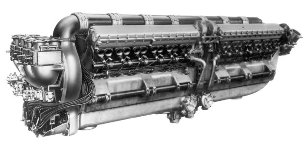
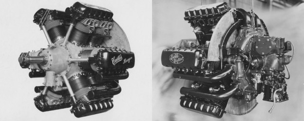
The Curtiss H-1640 Chieftain “hexagon” or “inline-radial” engine. The image on the left was taken in 1927; note “Curtiss Hexagon” is written on the valve covers. In front of each cylinder pair is the housing for the vertical shaft that drove the overhead camshafts. The image on the right was taken in 1932 and shows a more refined engine with “Curtiss Chieftain” written on the valve covers. Note the additional cooling fins surrounding the spark plugs. In both images, the baffle at the rear of each exhaust Vee forced cooling air into the intake Vee.

The Curtiss H-1640 was designed by Arthur Leak and Arthur Nutt. The Chieftain’s “hexagon” design was a combination of a radial and Vee engine. The intent was to combine the strengths of both engine configurations: the light and short features of a conventional radial with the narrow and high rpm (for the time) of a conventional Vee engine.

The Chieftain was arranged as if it were a 12-cylinder Vee engine cut into three sections, each being a four-cylinder Vee. The Vee engine sections were then positioned in a radial form 120 degrees apart (each cylinder bank being 60 degrees apart). The end result was a two-row, twelve-cylinder, inline radial engine. The H-1640 resembled a conventional radial engine except that the second cylinder row was directly behind the first.

An engine installation comparison of the air cooled Chieftain-powered XO-18 Falcon at left and a liquid-cooled D-12-powered Falcon at right. Note that while the Chieftain is a wider engine, it blends well with the fuselage and is shorter and not as tall as the Curtiss D-12.

Each four-cylinder Vee section had the cylinder exhaust ports on the inside of the Vee and the intake ports on the outside. Each inline cylinder pair had its own intake runner and dual-overhead camshafts that were enclosed in a common valve cover. The camshafts were driven via a single vertical shaft from the front of the engine. There were four valves per cylinder.

Cooling air was directed through each four-cylinder section’s exhaust Vee; here it met a baffle fitted to the rear of the engine and attached to the cowling. This baffle deflected the air and forced it to flow between the inline cylinders and behind the rear cylinder. The air then flowed into the intake Vee that was blocked off at the front. The air exited the cowling via louvers over the intake Vee.

The Curtiss O-1B Falcon that was redesignated XO-18 while it served as the test-bed for the Chieftain engine. Note the exposed valve covers and the exhaust stacks protruding through the engine cowling.

The pistons were aluminum and operated in steel cylinder barrels that were screwed and shrunk into cast aluminum cylinders with integral cooling fins. From U.S. patent 1,962,246 filed by Leak in 1931, it appears that the Chieftain’s connecting rods consisted of two halves that were bolted together. Each half was made up of one master rod and two articulating rods.

The H-1640 Chieftain had a bore of 5.625 in (143 mm) and a stroke of 5.5 in (140 mm), giving a total displacement of 1,640 cu in (26.9 L). The engine’s maximum diameter was 45.25 in (1.15 m). However, a special cowling was used, cut to allow the valve covers and exhaust stacks to protrude through, reducing the diameter of the cowling to 39 in (0.99 m). The engine was 52.3 in (1.33 m) long and weighed 900 lb (408 kg). The Chieftain had a 5.2 to 1 compression ratio and was rated at 600 hp (447 kW) at 2,200 rpm but developed 615 hp (459 kW). When the engine was pressed to 2,330 rpm, it produced 653 hp (487 kW). It was equipped with a centrifugal-type supercharger that allowed the engine to maintain sea-level power up to 12,000 ft (3,658 m). All Chieftain engines built were direct drive but geared versions had been planned. In addition, some design work on a four-row, 24-cylinder version of 1,200 hp (895 kW) had been done.

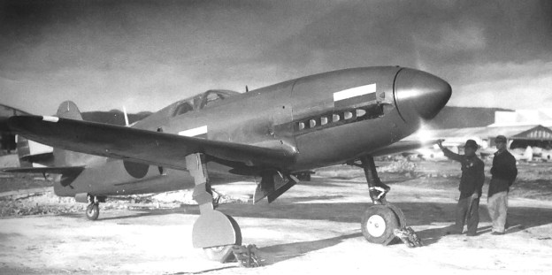
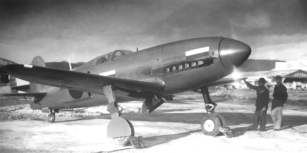
Side view of the Thomas-Morse XP-13 Viper with the Curtiss Chieftain engine and revised cowl. Not the louvers for the cooling air to exit the cowling.

Because the engine had an even number of cylinders per each row, a unique firing order was developed that alternated between the front and rear rows. When the engine was viewed from the rear, the cylinders were numbered starting with the cylinder bank at the 9 o’clock position and proceeding clockwise around the engine. The rear cylinder row had odd numbers, and the front cylinder row was even so that the rear cylinder of the cylinder bank at 9 o’clock was number 1 and the front was number 2. The firing order was initially 1, 10, 5, 7, 4, 11, 8, 3, 12, 2, 9, 6 but was later changed to 1, 10, 5, 2, 9, 11, 8, 3, 12, 7, 4, 6 in an effort to smooth out the engine.

The H-1640 Chieftain was first run in 1927 and flown in a modified Curtiss O-1B Falcon, redesignated XO-18, in April 1928. The Chieftain-powered test-bed aircraft was found to out-climb and have a higher ceiling than the standard liquid-cooled Curtiss D-12-powered Falcon. In addition, the top-speed of the two aircraft was the same, which was unheard of for that time period when liquid-cooled aircraft were faster than their air-cooled counterparts. However, the engine suffered cooling issues, and the aircraft was modified back to an O-1B in July 1930.

A comparison of the original cowling on the XP-13 at left and the updated cowling at right. The front of the cowling has been extended and angled out. The block-off plates in between the openings have been angled to funnel air into the enlarged openings.

Thomas-Morse also responded to the Army’s interest in using the Curtiss H-1640. The company’s Viper fighter prototype was built to use the Chieftain engine. This aircraft was tested at Wright Field in June 1929 and given the designation XP-13. Engine overheating was encountered, and a revised cowling was tried in an effort to provide adequate cooling for the H-1640. The new cowling had enlarged openings, and the blocked off sections were angled to force more air into the openings. However, over-heating persisted. The XP-13 was tested until September 1930, when a Pratt & Whitney R-1340C engine was installed and the aircraft redesignated XP-13A. Even though this engine was not as powerful, it was lighter and did not suffer the cooling issues present with the Chieftain. The XP-13A was found to be 15 mph (24 km/h) faster than the Chieftain-powered XP-13. Curtiss had planned to produce the Viper under the designation XP-14, but the H-1640 engine was lacking support so no aircraft were built.

Another Chieftain was installed in the Navy’s second Curtiss XF8C-1 prototype in 1930. The H-1640-powered aircraft was known as the Curtiss XOC3. It too suffered from engine over-heating. The Chieftain engine remained installed in the XOC3 until the aircraft was removed from the Navy’s inventory in April 1932.

Detail view of the revised cowling on the Chieftain-powered Thomas-Morse XP-13. The image on the left illustrates the angle of the block-off plates. Note the six, instead of eight, exhaust stacks of the upper cylinders. The last two stacks are combined and exit from a single stack aft of the cowling.

In October 1928, the Army ordered three Curtiss P-6 Hawk aircraft to be powered by the H-1640 engine and designated them XP-11. However, shortly after the order was placed, the engine’s cooling trouble became known and the engine’s development ceased. The aircraft were never built with the Chieftain engine.

A total of eight H-1640 engines were made with six going to the Air Corps and two to the Navy. While the Chieftain’s design may have been problematic, the event that directly led to its lack of support and ultimate abandonment was the merger of Curtiss Aeroplane and Motor Company with Wright Aeronautical in July 1929. After the merger, the liquid-cooled engines were provided by Curtiss and the air-cooled engines from Wright. There was no longer a need for the Chieftain, an air-cooled engine of rather dubious design. However, the concept of a hexagonal engine would be revisited with the Wright H-2120, and other hexagonal engines include the SNCM 137, the Junkers Jumo 222, and the Dobrynin series of aircraft engines..

Reportedly, at least one Curtiss H-1640 Chieftain survives and is in storage at the National Air and Space Museum’s Garber Facility in Silver Hill, Maryland.

The second Curtiss XF8C-1 re-engined with the H-1640 Chieftain and redesignated XOC3.

Sources:
Modern Aviation Engines, Volume 2 by Victor Page (1929)
– “The Curtiss ‘Chieftain’ Engine,” Flight by Erik Hildeshim (14 June 1928)
Dyke’s Aircraft Engine Instructor by A.L. Dyke (1929)
Aerosphere 1939 by Glenn Angle (1940)
Curtiss Aircraft 1907-1947 by Peter Bowers (1979/1987)
American Combat Planes of the 20th Century by Ray Wagner (2004)
Fighters of the United States Air Force by Dorr and Donald (1990)
General Dynamics Aircraft and their Predecessors by John Wegg (1990)

Kawasaki Ki-78 (KEN III)

By William Pearce

In the 1930s, Japanese aviation began to make strides toward closing the technological gap with the Western World. In 1938, the Aeronautical Research Institute of the University of Tokyo, led by Shoroku Wada, began a high-speed aircraft research program. Gathering data on high-speed flight was the primary objective, but it was felt that an attempt on the 3 km absolute world speed record was an obtainable goal.

The nearly complete and unpainted high-speed research aircraft, the Kawasaki Ki-78. Note the radiator housing on the fuselage side.

The aircraft project was known as KEN III (for Kensan III or Research III) and incorporated numerous advanced features new to Japanese aircraft. Approval was given for the aircraft’s development and a full-scale wooden mockup was finished in May 1941. Because of the outbreak of World War II, the project was taken over by the Imperial Japanese Army and designated Ki-78. A production contract for two prototypes was awarded to Kawasaki, under the direction of Isamu Imashi. Construction of the first prototype began in September 1941 at Kawasaki’s plant at Gifu Air Field.

The Ki-78 was an all-metal, low wing monoplane of conventional layout. The small streamlined fuselage was made as narrow as possible and was 26 ft 7 in (8.1 m) long. The wings possessed a laminar flow airfoil with a span of 26 ft 3 in (8 m) and an area of 118.4 sq ft (11 sq m). To reduce landing speed and improve low-speed handling, the wings incorporated drooping ailerons along with a combination of Fowler and split flaps, which was a first for a Japanese aircraft. When the Fowler flaps were deployed, the split flaps opened simultaneously to a similar extent. When the flaps were fully deployed, the ailerons automatically drooped down 10 degrees.

Factory fresh and unpainted view of the Ki-78. The aircraft is missing its outer gear doors and there is no horn-balance on the elevator.

Power for the Ki-78 was provided by an imported Daimler-Benz DB 601A inverted V-12 engine driving a three-blade metal propeller. The engine was not a Kawasaki Ha-40, a licensed copy of the DB 601. The DB 601 had a 5.91 in (150 mm) bore and 6.30 in stroke (160 mm), giving a total displacement of 2,070 cu in (33.9 L). It produced 1,175 hp (876 kW) at 2,500 rpm. The engine was modified by Kawasaki with the addition of a water-methanol injection system (another Japanese first) to boot the power output to 1,550 hp (1,156 kW) for short periods. The Ki-78 carried 66 gal (250 L) of fuel and 16 gal (60 L) of water-methanol.

The freshly-painted Ki-78 running-up its DB 601A engine. Note the hinge in the outer gear door to account for extension of the gear strut.

The freshly-painted Ki-78 running-up its DB 601A engine. Note the hinge in the outer gear door to account for extension of the gear strut.

Engine cooling was provided by two radiators: one mounted on each side of the rear fuselage. The radiators had a wide air inlet protruding slightly out from the fuselage. Airflow through each radiator was controlled by an actuated exit door. In addition, within the fuselage a small 60 hp (45 kW) turbine drove a fan to further assist cooling. The aircraft stood 10 ft 7/8 in (3.07 m) tall and weighed 4,255 lb (1,930 kg) empty.

The Ki-78 first flew on 26 December 1942 and was found to be extremely difficult to fly at low speeds and had poor stall characteristics. The aircraft was heavier than the design estimates, which increased the wing loading. Even with the special flaps and drooping ailerons, takeoff and landing speeds were both high at 127 mph (205 km/h) and 106 mph (170 km/h) respectively. In addition, elevator flutter was experienced at the relatively low speed of 395 mph (635 km/h) but was subsequently cured by fitting a horn-balance to the elevator.

Rear view of the Kawasaki Ki-78 as found by American troops after the war. Note the flat tailwheel and missing cockpit glass, flight instruments, and starboard tire. This view also displays the radiator exit door and elevator horn-balance.

High-speed flight tests were started in April 1943, and during the Ki-78’s 31st flight on 27 December, the aircraft achieved its maximum speed of 434.7 mph (699.6 km/h) at 11,572 ft (3,527 m). This was considerably less than the program’s speed goal of 528 mph (850 km/h). A study showed that extensive airframe modifications were needed to improve the Ki-78 flight performance. Consequently, the project was officially terminated after the aircraft’s 32nd flight on 11 January 1944. Only one prototype was built.

The unique Ki-78 survived the war but was crushed by American forces at Gifu Air Field in 1945.

The sole Ki-78 being crushed by American forces at Gifu Air Field, after the war, in 1945.

Sources:
World Speed Record Aircraft by Ferdinand Kasmann (1990)
Japanese Aircraft of the Pacific War by Rene Francillon (1970/2000)
General View of Japanese Military Aircraft in the Pacific War by Airview (1956)
http://forum.axishistory.com/viewtopic.php?t=32870
http://www.letletlet-warplanes.com/2008/06/04/the-kawasaki-ki-78-ken-iii-research-plane/

Bugatti 110P Racer top

Bugatti Model 100P Racer

By William Pearce

Ettore Bugatti was born in Milan, Italy on 15 September 1881. In 1909, he founded his own automobile company in Molsheim, in the Alsace region. The Alsace region was controlled by the German Empire until 1919, when control returned to France. The Bugatti race cars were incredibly successful in the 1920s and 1930s, collectively wining over 2,000 races. During that time period, Bugatti enjoyed seeing the small machines that bore his name defeat the larger and more powerful machines of his major rivals: the German vehicles from Mercedes-Benz and Auto Union.

Bugatti 110P Racer top

The elegant lines of the Bugatti 100P are well displayed in this image. (Hugh Conway Jr. image)

In 1936, Bugatti began to consider the possibility of building an aircraft around two straight eight-cylinder Bugatti T50B (Type 50B) engines, very similar to the engines that powered the Bugatti Grand Prix race cars. This aircraft would be used to make attempts on several speed records, most importantly, the 3 km world landplane speed record, then held by Howard Hughes in the Hughes H-1 Racer at 352.389 mph (567.115 km/h). Bugatti turned to Louis de Monge, a Belgian engineer, to help design the aircraft, known as the Bugatti Model 100P.

Bugatti 100P general arrangement drawing based off the original drawings by Louis de Monge. Note the arrangement of the power and cooling systems.

Before construction of the Bugatti 100P began, Germany demonstrated what if felt was its aerial superiority by setting a new 3 km world landplane speed record at 379.63 mph (610.95 km/h) in a Messerschmitt Bf 109 (V13) on 11 November 1937. Bugatti disliked Nazi-Germany and was very interested in beating their record. Bugatti and de Monge continued to develop the 100P for an attempt to capture the 3 km record from Germany.

The Bugatti 100P was one of the most beautiful aircraft ever built. With the exception of engine exhaust ports, the 25 ft 5 in (7.75 m) fuselage was completely smooth. The aircraft employed wood monocouque “sandwich” construction in which layers of balsa wood were glued and carved to achieve the desired aerodynamic shape. Hardwood rails and supports were set into the balsa wood to take concentrated loads at stress points, like engine mounts and the canopy. The airframe was then covered with tulipwood strips, which were then sanded and filled. Finally, the aircraft was covered with linen and doped. The Bugatti 100P stood 7 ft 4 in (2.23 m) tall and weighed 3,086 lb (1,400 kg).

The 100P had a 27 ft (8.235 m), one-piece wing that was slightly forward-swept. The wing had a single box spar that ran through the fuselage. The wing was constructed in the same fashion as the fuselage and housed the fully retractable and enclosed main gear. The wing featured a multi-purpose, self-adjusting flap system (U.S. patent 2,279,615). Both the upper and lower flap surfaces automatically moved up or down to suit the speed of the aircraft and the power setting (manifold pressure) of the engines. At high manifold pressure and very low airspeed, the flaps set themselves to a takeoff position. At low airspeed and low power, the flaps dropped into landing position, and the landing gear was automatically lowered. In a dive, the flaps pivoted apart to form air brakes.

Image of the nearly complete Bugatti 100P still under construction in Paris. The cooling-air inlet in the butterfly tail can be easily seen.

The Bugatti tail surfaces consisted of two butterfly units and a ventral fin at 120-degree angles (French patent 852,599). They were constructed with the same wood “sandwich” method used on the fuselage and wing. The tip of the ventral fin incorporated a retractable tail skid.  For cooling, air was scooped into ducts in the leading edges of the butterfly tail and ventral fin. The air was turned 180 degrees, flowed into a plenum chamber in the aft fuselage, and passed through a two section radiator (one section for each engine) located behind the rear engine. The now-heated air again turned 180 degrees and exited out the fuselage sides into a low pressure area behind the trailing edge of the wings. The high pressure at the intake and low pressure at the outlet created natural air circulation that required no fans or blowers (U.S. patent 2,268,183).

The two Bugatti T50B straight eight-cylinder engines were specially made for the 100P aircraft. The engine crankcases were made of magnesium to reduce weight, and each engine used a lightweight Roots-type supercharger feeding two downdraft carburetors. The T50B had a bore of 3.31 in (84 mm) and a stroke of 4.21 in (107 mm), giving a total displacement of 289 cu in (4.74 L). Twin-overhead camshafts actuated the two intake and two exhaust valves for each cylinder. The standard T50B race car engine produced 480 hp (358 kW) at 5,000 rpm. An output of 450 hp (336 kW) at 4,500 rpm is usually given for the 100P’s engines; however, de Monge stated the engines planned for the 100P were to produce 550 hp (410 kW) each. The engines were situated in tandem, behind the pilot. The front engine was canted to the right and drove a drive shaft that passed by the pilot’s right side. The rear engine was canted to the left and drove a drive shaft that passed by the pilot’s left side. The two shafts joined into a common reduction gearbox just beyond the pilot’s feet. The gearbox allowed each engine to drive a metal, two-blade, ground-adjustable Ratier propeller. Together, the two propeller sets made a coaxial contra-rotating unit. From the gearbox, the rear propeller shaft (driven by the front engine) was hollow, and the front shaft (driven by the rear engine) rotated inside it (U.S. patent 2,244,763).

Image of the two T50B engines in the Bugatti 100P while at the Ermeronville estate. Note the radiator at left , how the engines are canted within the fuselage, and how the exhaust ports on the front engine protrude through the fuselage.

Once the new design was finalized in 1938, construction of the 100P was begun at a high quality furniture factory in Paris. While construction proceeded, it was obvious that war would break out soon. France did not have any fighters that could match the performance of their German counterparts. The French Air Ministry felt the 100P could be developed into a light pursuit or reconnaissance fighter and awarded a contract to Bugatti in 1939. This fighter was to be equipped with at least one gun mounted in each wing, an oxygen system, and self-sealing fuel tanks. Most aspects of the fighter are unknown, but it is possible that it was larger than the 100P and incorporated 525 hp (391 kW) T50B engines installed side-by-side in the fuselage driving six-blade coaxial contra-rotating propellers with a 37-mm cannon firing through the propeller hub. Because of France’s surrender, the aircraft never progressed beyond the initial design phase.

The Bugatti 100P, finally in all its glory after being completely restored by the Experimental Aircraft Association. Note the fairing for the rear engine ‘s exhaust ports above the wing. (Hugh Conway Jr. image)

Bugatti’s contract included a bonus of 1 million francs if the 100P racer captured the world speed record which the Germans had raised to 463.919 mph (746.606 km/h) with a Heinkel He 100 (V8) on 30 March 1939 and raised again to 469.221 mph (755.138 km/h) with a Messerschmitt Me 209 (V1) on 26 April 1939. Bugatti and de Monge felt the 100P was capable of around 500 mph (800 km/h). In addition, a smaller version of the racer, known as the 110P, was planned; it featured a 5 ft (1.525 m) reduced wingspan of 22 ft (6.7 m). The 110P was to have the same engines as the 100P, but the top speed was estimated at 550 mph (885 km/h). However, other sources indicate these figures were very optimistic, and the expected performance was more around 400 mph (640 km/h) for the 100P and 475 mph (768 km/h) for the 110P.

The 100P was nearly complete when Germany invaded France. As the Germans closed in on Paris in June 1940, the Bugatti 100P and miscellaneous parts, presumably for the 110P, were removed from the furniture factory and loaded on a truck. The 100P was taken out into the country and hidden in a barn on Bugatti’s Ermeronville Castle estate 30 mi (50 km) northeast of Paris.

Bugatti 100P on display at the EAA AirVenture Museum in Oshkosh, Wisconsin. The cooling air exit slots on the left side of the aircraft can be seen on the wing trailing edge fillet. Also note the tail skid on the ventral fin.

Ettore Bugatti died on 21 August 1947 with the 100P still stashed away in Ermeronville. The aircraft was purchased by M. Serge Pozzoli in 1960 but remained in Ermeronville until 1970 when it was sold to Ray Jones, an expert Bugatti automobile restorer from the United States. Both Pozzoli and Jones offered the 100P to French museums but were turned down. Jones acquired the 100P with the intent to complete the aircraft; however, that goal could not be completed due to missing parts. Jones had the two Bugatti T50B engines removed from the airframe before everything was shipped to the United States. Dr. Peter Williamson purchased the airframe and moved it to Vintage Auto Restorations in Ridgefield, Connecticut in February 1971 to begin a lengthy restoration. Les and Don Lefferts worked on the project from 1975 to 1979. Louis de Monge was now living in the United States and assisted with some aspects of the restoration work before he passed away in 1977. In 1979, the unfinished 100P was donated to the Air Force Museum Foundation with the hope of having the restoration completed and the aircraft loaned to a museum for display. However, the aircraft sat until 1996 when it was donated to the Experimental Aircraft Association (EAA) in Oshkosh, Wisconsin and finally underwent a full restoration. The restored, but engineless, Bugatti 100P is currently on display at the EAA AirVenture Museum.

The original engines out of the Model 100P were reportedly not the final version of the engines intended for the actual speed record run. Both engines still exist and are installed in Bugatti automobiles. The front engine is installed in Ray Jones’ 1937 Type 59/50B R Grand Prix racer, and the rear engine is installed in Charles Dean’s 1935 Type 59/50B Grand Prix racer. Since January 2009, Scotty Wilson has led an international team, including Louis de Monge’s grand-nephew, Ladislas de Monge, to build a flying replica of the Bugatti 100P in Tulsa, Oklahoma. Piloted by Wilson, the Bugatti 100P replica flew for the first time on 19 August 2015. Tragically, Scotty Wilson was killed when the replica crashed during a test flight on 6 August 2016.

Bugatti 100P on display at the EAA AirVenture Museum in Oshkosh, Wisconsin. Simply one of the most beautiful aircraft ever built.

Sources:
The Bugatti 100P Record Plane by Jaap Horst (2013)
World Speed Record Aircraft by Ferdinand Kasmann (1990)
Airplane Racing by Don Berliner (2009)
The Classic Twin-Cam Engine by Griffith Borgeson (1979/2002)
http://www.bugattiaircraft.com/kalempa.htm by Alex Kalempa
http://www.airventuremuseum.org/collection/aircraft/2Bugatti Model 100 Racer.asp
http://www.airventuremuseum.org/collection/aircraft/2Bugatti Model 100 Racer Facts.asp
http://morlock68.pagesperso-orange.fr/bugatti.htm
http://bugatti100p.com/
http://en.wikipedia.org/wiki/Bugatti
http://kfor.com/2016/08/06/historic-replica-airplane-the-bugatti-100p-crashes-near-burns-flat-pilot-and-designer-scotty-wilson-dies/

FIAT AS.6 Aircraft Engine (for the MC.72)

By William Pearce

For the 1929 Schneider Trophy Contest, Italy fielded a number of different aircraft and engine combinations. The end result was that none of their entries were developed enough be victorious, and Britain won the contest for the second time in a row. If the British were to win the competition in 1931, the Schneider Contest would be over, and Britain would retain permanent possession of the Schneider Trophy.

Side view of the FIAT AS.6 illustrating the engine’s length. In the middle of the engine at bottom, two water pumps can clearly be seen with coolant lines feeding the individual cylinders. Right behind the propeller hubs, one of the front engine section’s magnetos can be seen. The small pipes leading from the middle of the engine toward the rear engine section and from right behind the front engine section’s cylinder bank and toward the front engine are for the air starter.

To prevent a British victory in 1931, Italy focused on developing one aircraft and one powerplant for its Schneider efforts. Macchi Aeronautica was chosen to develop the airframe, and with the design talents of Mario Castoldi, the Macchi-Castoldi 72 (MC.72) was born. FIAT was tasked with developing an engine to power the MC.72 and defeat the British. Time was short for FIAT because the MC.72 would be designed around the engine.

As the FIAT engine team, led by Tranquillo Zerbi, began to develop a new powerplant, they quickly realized that there was not enough time to start from scratch; the engine that was to power the MC.72 would have to start from an existing engine. FIAT’s best powerplant at the time was the 1,000 hp (746 kW) AS.5 (Aviazione Spinto) V-12 engine. This engine was used in one of Italy’s 1929 Schneider racers, the FIAT C.29. The Italian team knew the engine would need at least 2,300 hp (1,715 kW) to win the 1931 Schneider Contest and began developing a supercharger, increasing the engine’s compression, and incorporating other enhancements to attempt to achieve the desired power. But even early on, Zerbi knew the AS.5 engine could not develop the power needed to defeat the British.

While working on the enhanced AS.5, a proposal was made to mount two AS.5 engines back-to-back, creating a V-24 engine. FIAT moved forward with the concept and called it the AS.6, but it was not as simple as bolting two AS.5 engines together. The AS.5 engine sections were not coupled together. They shared a common magnesium crankcase and an induction manifold, and there was only one throttle linkage. Everything else (the ignition, coolant, and oil systems) was independent for each engine section.

Rear view of the FIAT AS.6 showing the two four-barrel carburetors feeding the supercharger. Directly below the supercharger are fuel pumps and the two magnetos for the rear engine section.

A 0.60 gear reduction for the propellers would be driven from the back of each AS.5 engine section (middle of the V-24 power plant). A drive shaft would be taken from the gear reduction of each engine. These drive shafts would travel through the Vee of the front engine and to the nose of the aircraft.  The rear engine drove a 69.96 in (1.77 m) shaft inside the front engine’s 52.52 in (1.334 m) shaft. Via the drive shaft, each engine drove one pair of propellers that together made a coaxial contra-rotating unit; the front engine drove the rear propeller, and the rear engine drove the front propeller. Coaxial contra-rotating propellers allowed for a blade short enough to avoid sea spray and also cancelled out the torque of the engine.

The rear engine section powered a supercharger that supplied 6.5 psi (0.45 bar) of air to both engine sections through a manifold approximately 88.58 in (2.25 m) long. The supercharger took 250 hp (186 kW) to run and spun at 17,000 rpm. The propeller pitch was ground adjustable. The front and rear propellers were adjusted to different pitches to compensate for the supercharger’s drain on the second engine section (front propeller) and efficiency differences between the first and second set of blades. The metal propellers were 8.5 ft (2.59 m) in diameter.

A detailed view inside the FIAT AS.6. The propeller gear reduction and drive shafts can clearly be seen. Note the individual cylinders on the far side of the engine and how the two crankcase sections are joined in the middle.

The FIAT AS.6 was a liquid-cooled, 60-degree, V-24 engine. It used individual steel cylinders, each with a 5.4 in (138 mm) bore and 5.5 in (140 mm) stroke, giving a total displacement of 3,067 cu in (50.256 L). The engine had a maximum compression ratio of 7 to 1. Four valves per cylinder were actuated by dual-overhead camshafts. The AS.6 was 132.48 in (3.365 m) long, 27.64 in (0.702 m) wide, 38.43 in (0.976 m) tall, and weighed 2,050 lb (930 kg). The engine was started by compressed air fed from a distribution pump located on the gear reduction housing. The rear engine section was started first.

Each inboard camshaft was driven from a gear parallel to and smaller than the propeller reduction gear. The outboard camshaft was geared to the inboard camshaft. Oil and water pumps were gear driven from the crankshaft. Each bank of each engine section had its own water pump. Ignition for each engine section was provided by two magnetos. The rear engine section’s magnetos were crankshaft driven and located below the supercharger. The front engine section’s magnetos were located on top of the engine, near the propellers, and driven from the outer (front engine’s) propeller shaft. Each cylinder had two spark plugs installed perpendicular to its axis: one located below the intake valves and the other below the exhaust valves.

Sectional view of the FIAT AS.6 illustrating the propeller drive shafts. Note the gear drive for the camshafts at top, the oil and water pumps at bottom, the front engine section’s magnetos at front, and the supercharger and rear engine section’s magnetos at rear.

During development, the AS.6 engine suffered many technical difficulties. Issues were encountered with spark plugs, ignition, coolant flow, fuel metering, induction, exhaust valves, connecting rods, and supercharger drive, to name a few. Much time was spent to resolve the issues. By April 1931, the engine completed a one hour run, producing 2,300 hp (1,715 kW).

The AS.6 engine was installed in the first of five MC.72 aircraft (MM 177 to MM 181), and flight trials began in the summer of 1931. Almost immediately, a new and very dangerous problem was discovered: while in flight, the engine would backfire at high power and high speed. The cause of this issue was a bit of a mystery because the engine ran perfectly on the ground but not during flight. Even with the engine’s difficulties, the aircraft had attained a speed of 375 mph (604 km/h). To demonstrate the backfire phenomenon, Capt. Giovanni Monti flew the MC.72 (MM 178) for FIAT and Macchi engineers on 2 August 1931. Sadly, a backfire ignited the volatile air/fuel mixture in the long induction manifold and caused it to explode. The MC.72 crashed into Lake Garda. Monti was killed in the crash.

FIAT AS.6 engine being test run in a MC.72.

With the Schneider Contest one month away and the cause of the backfiring still unknown, the decision was made to withdrawal the AS.6-powered MC.72 from the race. The British would make an uncontested flight for the Schneider Trophy and retain it permanently. But the Italians had decided to make an attempt on the absolute world speed record on 13 September 1931, the same day as the Schneider race. On 10 September, Lt. Stanislao Bellini was making a practice run to exceed 394 mph (634 km/h), the fastest the MC.72 had flown, when the aircraft (MM 180) flew straight into rising terrain. Debris found some distance from the impact site indicated that there had been an in-flight fire or explosion. Subsequently, the MC.72 was withdrawn from flight status.

The vision of what the AS.6 and MC.72 could have been continued to stir in the minds of various officials, and a new record attempt was planned. Believing the backfire issue was fuel related, the Italians wanted the help of Rod Banks: the Britain who developed the special fuel used for Rolls-Royce’s R Schneider engine. Banks was closely associated with the British Schneider effort but was not employed by Rolls-Royce or Supermarine. In 1932, the British sent Banks to see what could be done to improve the AS.6 engine.

Rear view of a preserved FIAT AS.6 engine at the Centro Storico Fiat in Turin, Italy. (Gianni image)

Banks arrived to find the AS.6 engine producing 2,400 hp (1,790 kW), but not reliably. A special sprint version of the engine had produced 2,850 hp (2,125 kW), but only for one minute. One of the issues Banks discovered was that the Italians had not fully accounted for the ram effect of having air forced into the induction by the forward speed of the aircraft. The AS.6 ran well on the ground, but the 400+ mph (640+ km/h) air being rammed into the intake caused a lean condition. This lean condition led to a backfire that ignited the air/fuel mixture in the long induction.

Banks knew how Rolls-Royce had dealt with this issue. Rolls-Royce had used a Kestrel engine to run a blower that supplied ram air for the R engine being tested. Banks had the Italians use a similar set-up that provided ram air at 435 mph (700 km/h) into the AS.6’s intake. The AS.6 engine was tuned under these conditions and no longer backfired. The sprint engine was able to produce 2,850 hp (2,125 kW) for an hour.

Warrant Officer Francesco Agello and the FIAT AS.6-powered MC.72 after setting the 3 km absolute world speed record at 440.682 mph (709.209 km/h) on October 23, 1934.

Late in 1932, the MC.72 took to the air once more; the AS.6 engine now produced a reliable 2,400 hp (1,790 kW). On 10 April 1933, Warrant Officer Francesco Agello set a 3 km absolute world speed record at 423.824 mph (682.078 km/h) in MM 177. On 8 October 1933, LtCol. Guglielmo Cassinelli captured the 100 km speed record at 391.072 mph (629.370 km/h). On 21 October, Capt. Pietro Scapinelli won the Blériot Cup in MM 179 for flying in excess of 600 km/h for over half an hour. His actual speed over the 30 minute run was 384.799 mph (619.274 km/h).

A year later, an AS.6 sprint engine was installed in the MC.72 (MM 181). This engine produced 3,100 hp (2,312 kW) at 3,300 rpm; 11.5 psi (0.79 bar) of boost was provided by the supercharger spinning at 19,000 rpm. On 23 October 1934, Agello was again at the controls and upped the 3 km record to 440.682 mph (709.209 km/h)—Agello was the fastest man on earth. This speed has never been surpassed by a piston-powered seaplane.

The record-setting MC.72 (MM 181) and an AS.6 engine are on display in the Museo Storico dell’Aeronautica Militare in Vigna di Valle, Italy. Another AS.6 engine is on display at the Centro Storico Fiat (Fiat Historic Center) in Turin, Italy.

The FIAT AS.6 displayed alongside the MC.72 (MM 181) at the Museo Storico dell’Aeronautica Militare in Vigna di Valle, Italy.

Sources:
The Schneider Trophy Story by Edward Eves (2001)
Schneider Trophy Seaplanes and Flying Boats by Ralph Pegram (2012)
Schneider Trophy Aircraft 1913-1931 by Derek James (1981)
Schneider Trophy Racers by Robert Hirsch (1993)
Jane’s All the World’s Aircraft 1935 by Grey and Bridgman (1935)
Italian High-Speed Airplane Engines NACA Technical Memorandum No. 944 by C. F. Bona (1935/1940) 17.7mb pdf
Technical Aspects of the Schneider Trophy and the World Speed Record for Seaplanes by Ermanno Bazzocchi (1971)
Idrocorsa Macchi by Apostolo and Cattaneo (2007)
I Kept No Diary by F.R. Banks (1978)

Bellanca 28-92 Trimotor

By William Pearce

The Bellanca 28-92 (construction no. 903) was developed by Giuseppe Bellanca in 1937 for Capt. Alexandru Papana. Papana was a Romanian Air Force pilot who planned to use the Bellanca on a long-distance good-will flight from New York to Bucharest. He named the aircraft Alba Iulia 1918 to commemorate the assembly of ethnic Romanian delegates who unified what is modern-day Romania at Alba Iulia, Transylvania in 1918. The aircraft carried the Romanian registration YR-AHA.

Alex Papana poses with the Bellanca 28-92. The Romanian registration can be seen on the wings but the name, “Alba Iulia 1918,” has yet to be applied. Note the propellers do not have spinners.

The Bellanca 28-92 was a low-wing, single-seat, trimotor design. The fuselage was of tubular steel construction and covered by aluminum back to the cockpit. Aft of the cockpit, the fuselage was covered with fabric. The wings and tail were plywood-covered, and the control surfaces were covered by fabric. The main undercarriage partially retracted into the rear of the wing engine nacelles, but the tailwheel did not retract.

Installed in each wing of the aircraft was a 250 hp (186 kW) Menasco C6S4 engine. The C6S4 Super Buccaneer was a direct drive, air-cooled, inverted, straight-six aircraft engine. The C6S4 was supercharged and displaced 544 cu in (8.9 L). Each C6S4 engine drove a 6 ft 6 in (1.98 m) diameter, two-blade, adjustable-pitch propeller.

The complete 28-92 with spinners and “Alba Iulia 1918” painted on the side. “YR” is painted on the tail, and the registration “YR-AHA” is repeated on the upper fuselage behind the cockpit..

A 420 hp (313 kW) Ranger SGV-770 engine was in the nose of the 28-92. The SGV-770 was an air-cooled, inverted, V-12 engine. The engine was supercharged, displaced 773 cu in (12.7 L), and had gear reduction for the 8 ft 3 in (2.51 m) diameter, two-blade, adjustable-pitch propeller.

All of the trimotor’s engines were hand cranked to start. The 28-92 had a fuel capacity of around 715 gallons (2,707 L). The aircraft had a span of 46 ft 4 in (14.1 m), a length of 28 ft 4 in (8.6 m), and weighed 4,700 lb (2,132 kg) empty. The 28-92 had a top speed of 285 mph (459 km/h) and a 3,000 mile (4,828 km) range at 250 mph (402 km/h) or a 4,160 mile (6,695 km) range at 200 mph (322 km/h). Landing speed was 75 mph (121 km/h).

Front view of the 28-92 trimotor illustrating the limited visibility from the cockpit while the aircraft was on the ground.

Papana was inexperienced with superchargers and inadvertently overboosted the engines during his first test flight in the trimotor. The incident led to a disagreement with Bellanca, and Papana cancelled his order for the aircraft. Since the 28-92 was complete and neither Papana nor the Romanian government paid for the aircraft, it remained at the Bellanca factory.

In 1938, Bellanca registered the aircraft in the United States as NX2433 and entered it in the Bendix Trophy cross-country race. Frank Cordova was the pilot for the race, and the trimotor flew as race number 99. Unfortunately, because of engine trouble, the aircraft did not finish the cross-country race. The Ranger engine in the nose quit, but Cordova continued to fly on the two Menasco engines for another 1,000 miles (1,609 km), landing in Bloomington, Illinois. A new rule for the 1938 races stated that no aircraft entered in the Bendix race could compete in the Thompson Trophy race, so the trimotor was returned to the Bellanca factory.

Bellanca 28-92 trimotor with Art Bussy at the controls for the 1939 Bendix race. The aircraft looked the same for the 1938 race except the race number was 99.

The 28-92 was again entered for the 1939 Bendix Trophy race, this time piloted by Art Bussy. Competing as race number 39, the aircraft finished second in the Los Angeles to Cleveland race with an average of 244.486 mph (393.462 km/h). Continuing on to New York, Bussy and the trimotor again finished second, averaging 231.951 mph (373.290 km/h) for the total distance from Los Angeles to New York.

Because of the start of World War II, all air races and record flights were put on hold. The Bellanca 28-92 trimotor was of little use during this time. The aircraft was eventually purchased by the Ecuadorian Air Force and served in South America from 1941 to 1945. Reportedly, the 28-92 was abandoned at a small airfield in Ecuador; a sad end for a unique aircraft.

Rear 3/4 view of the Bellanca 28-92 showing the aircraft’s clean lines.

*Sources disagree on what number the aircraft used for which year. Images reportedly from 1939 show number 39 on the fuselage, but it is possible that they are in error and race number 99 could have been used in 1939 and race number 39 used in 1938.

Sources:
Aircraft of Air Racing’s Golden Age by Robert and Ross Hirsh (2005)
The Air Racer by Charles Mendenhall (1994)
Aerosphere 1939 by Glenn Angle (1940)
Bellanca Specials 1925 – 1940 by Theo Wesselink (2015)
Jane’s all the World’s Aircraft 1938 by Grey and Bridgman (1938)

Chrysler A57 Multibank Tank Engine

By William Pearce

When the United States entered World War II, there was a desperate need for a medium tank engine. Chrysler responded with a very unusual idea. Chrysler had its 251 cu in (4.1 L) straight six-cylinder, L-head engine available in large numbers. Under the direction of Executive Engineer Harry Woolson, the Engine Design department, headed by Mel Carpentier, designed a new powerplant that utilized the 251 cu in (4.1 L) engine. The basic idea was to combine five of these six-cylinder engines into a five-bank, 30-cylinder, single engine for medium tanks. This new engine, referred to as the Multibank, was given the designation A57.

Chrysler A57 engine as displayed at the Walter P. Chrysler Museum. Note the central water pump feeding the five engine banks, the individual distributors for each engine bank, and the row of carburetors at top: three on the left and two on the right.

The Multibank A57 engine had a large cast iron crankcase that formed the central structure of the powerplant. Five Chrysler 251 cu in (4.1 L) six-cylinder engines were bolted to this central crankcase. Two of the engines were bolted to the lower portion of the crankcase, one on each side, with their cylinders angled 7-1/2 degrees above horizontal. Two addition engines were bolted to the crankcase above the first two, with their cylinders 27 degrees above horizontal. The fifth engine was bolted vertically at the top of the crankcase. The five six-cylinder engines made up the banks of the A57.

The A57 engine was mounted in the rear of the tank, and the crankshaft output flanges faced the front of the tank. The A57 retained the five crankshafts of the five six-cylinder engines.  A drive gear was coupled to the crankshaft of each engine bank. These five drive gears meshed with a single, central gear (all gears had herringbone teeth). The central gear drove the output shaft of the power plant. The output shaft went through the radiator and drove the cooling fan and clutch, which was attached to a drive shaft and then transmission.

A view of the gear case revealing the central drive gear that is driven by five outer gears, each coupled to their respective engine bank’s crankshaft. (Adrian Barrell image)

The A57 was originally equipped with five belt-driven water pumps. However, the belts would often break because of the alternating loads on the crankshaft pulleys. The design was changed to a single water pump with five outlets (one for each engine bank). This single water pump was driven by an accessory shaft from the central drive gear located on the opposite end of the central crankcase. Also at the rear of the tank, each engine bank had its own ignition coil and distributor that was gear-driven from the camshaft.

The first production engines had a single-barrel carburetor mounted directly on the intake manifold for each of the five engine sections. The different pipe lengths and contours leading from the air cleaner to the carburetors resulted in unequal fuel distribution. Metal vanes were added to direct airflow, and ultimately the five carburetors (each connected to its respective engine with a downpipe) were relocated in the same plane above the engine. This change simplified throttle linkages, the air cleaner arrangement, and maintenance.

The A57 Multibank had two oil pumps located in the central crankcase. One oil pump was a scavenge pump to transfer oil to a remote reservoir. The second pump was pressure pump that took oil from the reservoir and delivered high-pressure oil to all five engine sections.

The 5,244 lb (2,379 kg) Chrysler A57 engine package being installed in a M4A4 Sherman tank. Note the engine’s size in comparison to the installers.

The A57 engine had a 3.4375 in bore and 4.50 in stroke, giving a total displacement of 1,253 cu in (20.5 L) from its 30 cylinders. The engine produced 445 hp (332 kW) and 1,060 lb ft (1,437 N m) of torque at 2,400 rpm. Given the arrangement of the engine sections, the Multibank was a relatively short but heavy engine, weighing 5,244 lb (2,379 kg) including radiator, cooling fan and clutch. Construction of the A57 utilized existing tooling from the 251 cu in (4.1 L) Chrysler six-cylinder engine, and the engines shared cylinder blocks, cylinder heads, pistons, connecting rods, and crankshafts.

On 3 June 1942, nine months after the initial engine discussion, the first of 109 M3A4 tanks were built with the A57 engine. However, the M3A4 tank was quickly replaced by the M4A4 Sherman tank, the first being produced on 30 June 1942. From April 1942 to September 1943, 9,965 Chrysler Multibank engines were built; 7,500 engines were installed in production tanks, and the remainder were built as spare engines. The A57 engine proved to be a very durable, reliable, and efficient power plant for medium tanks. Reportedly, the engine would still run with two of the five engine banks disabled from combat damage.

A number of Chrysler A57 Multibank engines survive, and some are still in working order in restored tanks.

Side view showing the relatively short length of the of the A57 engine at the Walter P. Chrysler Museum.

While similar engine concepts, no direct relation has been found between the Chrysler Multibank and the Perrier-Cadillac 41-75.

Sources:
Chrysler Engines 1922-1988 by Willem Weertman (2007)
Some Unusual Engines by L. J. K. Setright (1975)
http://autospeed.com/cms/title_The-Chrysler-A57-MultiBank-Engine/A_112613/article.html
http://en.wikipedia.org/wiki/Chrysler_A57_multibank
http://hmvf.co.uk/forumvb/showthread.php?10960-M4A4-restoration (amazing M4A4 restoration)
http://sbiii.com/chrymult.html

Mercedes-Benz T80 (Type 80) LSR Car

By William Pearce

German auto racer Hans Stuck wished to capture the world land speed record for himself and Germany. In the late 1930s, he worked to put together a team to achieve this goal. By 1937, Stuck had convinced Wilhelm Kissel, Chairman of Daimler-Benz AG, to have Mercedes-Benz develop and build the vehicle, which Dr. Ferdinand Porsche had agreed to design. Stuck also obtained project approval from Adolf Hitler, who saw the record as another propaganda tool to demonstrate Germany’s supposed technological superiority.

Mercedes-Benz T80. Hans Stuck’s project designed for over 373 mph (600 km/h) by Dr. Ferdinand Porsche. (Mercedes-Benz image)

The vehicle was officially known as the Mercedes-Benz T80 or Type 80. Dr. Porsche had first targeted a speed of 342 mph (550 km/h), utilizing a 2,000 hp (1,490 kW) engine. When the car was first planned in 1937, the speed record was held by Malcolm Campbell in the last of his Blue Bird cars at 301.473 mph (485.174 km/h) covering one km (.6 mi) and 301.129 mph (484.620 km/h) covering one mile (1.6 km). However, from 1937 through 1939, George Eyston in Thunderbolt and John Cobb in Railton had raised the record a total of five times, with Cobb achieving 369.74 mph (595.04 km/h) for the km (.6 mi) and 368.86 mph (593.62 km/h) for the mile (1.6 km) in August 1939. As these speed record challengers raised the record, the T80’s speed goal was raised as well. More power was made available from the engine, and when the T80 was nearly finished in 1939, the target speed for its record run was 373 mph (600 km/h) after 3.7 mi (6 km) of acceleration.

The T80 cost 600,000 Reichsmarks to complete; that is about $4 million in today’s USD. Aerodynamics specialist Josef Mikcl helped streamline the car’s body, which was built by aircraft manufacturer Heinkel Flugzeugwerke. The T80 incorporated a Porsche-designed enclosed cockpit, low sloping hood, and rounded fenders. The rear wheels were encased in elongated tail fins to help stabilize the vehicle at speed. Two small wings at the middle of the car provided downforce and ensured stability. The heavily streamlined twin-tailed body achieved a drag coefficient of 0.18, a very low figure even by today’s standards.

Chassis of the T80 with the DB 603 engine connected to the transmission. Note the drive arrangement to the four rear wheels and the fuel tank. (Mercedes-Benz image)

The car had three axles: the front provided steering, and the two rear axles were driven by a 2,717 cu in (44.5 L) Daimler-Benz DB 603 inverted V-12 aircraft engine. Ernst Udet, director of Germany’s Aircraft Procurement and Supply, provided the third DB 603 prototype engine for installation in the T80. The supercharged DB 603 engine with mechanical fuel injection was specially tuned to 3,000 hp (2,240 kW). The engine ran on a special mixture of methyl alcohol (63%), benzene (16%), ethanol (12%), acetone (4.4%), nitrobenzene (2.2%), avgas (2%), and ether (0.4%); it utilized MW (methanol-water) injection for charge cooling and anti-detonation.

Power from the engine was transmitted to the four drive wheels via a hydraulic torque converter to a single-speed final drive. To maintain traction, the T80 had a mechanical “anti-spin control” device. The front and rear wheels each had a sensor to mechanically detect wheel spin. If the rear wheels began to spin faster than the front, fuel to the engine was automatically reduced.

The framework of the T80’s body is shown here, illustrating how much longer the body was than the chassis. (Mercedes-Benz image)

The T80 was 26 ft 8 in (8.128 m) long and 4 ft 1 in (1.245 m) tall. Its body width was 5 ft 9 in (1.753 m) and 10 ft 6 in (3.20 m) wide including the wings. All six wheels were 7 in x 32 in and had a 4 ft 3 in (1.295 m) track. The vehicle weighed about 6,390 lb (2,900 kg).

The T80 vehicle had been unofficially nicknamed Schwarzer Vogel (Black Bird) by Hitler and was to be painted in German nationalistic colors complete with German Eagle and Swastika. Hans Stuck would have driven the T80 over a special stretch of the Dessau Autobahn (now part of the modern A9 Autobahn), which was 82 ft (25 m) wide and 6.2 mi (10 km) long with the median paved over. The record attempt was set for January 1940 and would have been the first absolute land speed record attempt in Germany.

The T80 as it looks now in the Mercedes-Benz Museum. (Mercedes-Benz image)

However, the outbreak of the war prevented the T80 run. In fact, the vehicle’s finishing touches were never completed, and it never moved under its own power. After the record attempt was cancelled, the T80 was garaged. In late February 1940, the DB 603 engine was removed, and the vehicle was stored in Karnten, Austria for the duration of the war. The Mercedes-Benz T80 was unknown outside of Germany until discovered by the Allies after World War II. Fortunately, the T80 survived the war relatively unscathed and was eventually moved into the Mercedes-Benz Museum in Stuttgart, where it is on permanent display in the Silver Arrows – Races & Records Legend room. (The T80’s body is on display. The chassis is in storage at a museum warehouse.)

On 16 September 1947, John Cobb achieved 394.19 mph (634.39 km/h) in the twin Napier Lion-powered Railton Mobil Special, surpassing the T80’s calculated Autobahn record run speed. However, after discovering the T80, the Allies had been quoted an astounding top speed of 465 mph (750 km/h) for the T80. Had the T80 been capable of this estimated top speed, the corresponding record would have been unequaled until 1964 when Craig Breedlove hit 468.72 mph (754.33 km/h) in the jet-powered Spirit of America. In addition, the T80 would still hold the record for the fastest piston-engined, wheel-driven vehicle.

Mercedes-Benz T80 leading the Silver Arrow display at the Mercedes-Benz Museum. (Mercedes-Benz image)

This article is part of an ongoing series detailing Absolute Land Speed Record Cars.

Sources:
The V12 Engine by Karl Ludvigsen (2005)
– “Rekord Krieg” by Charles Armstrong-Wilson. Racecar Engineering, Vol 22 No 1 (January 2012)
http://en.wikipedia.org/wiki/Mercedes-Benz_T80
http://www.autoevolution.com/news/mercedes-benz-t80-the-record-car-that-never-was-25555.html

Arsenal VB 10-02 under construction

Arsenal VB 10 Heavy Interceptor Fighter

By William Pearce

In January 1937, the Ministère de l’Air (French Air Ministry) gave Arsenal de l’Aéronautique a contract to develop a twin-engine heavy interceptor fighter built from wood and powered by two 690 hp (515 kW) Hispano-Suiza 12X engines. The engines were to be mounted in tandem inside the fuselage driving coaxial propellers in the nose. Through the course of several changes, the aircraft’s design was developed into the all-aluminum VB 10 fighter. The VB 10 was designed in 1938 by Michel Vernisse and Robert Badie; the initials of their last names formed the ‘VB’ of the aircraft’s designation.

Arsenal VB 10-01 rear

The Arsenal VB 10-01 prototype powered by two 860 hp (641 kW) Hispano-Suiza 12Y-31 V-12 engines. Note the obstructed rear view from the flush canopy.

The VB 10 was a low-wing monoplane in a standard taildragger configuration with retractable undercarriage and a single-seat. It was a large aircraft with a span of 50 ft 10 in (15.49 m), length of 42 ft 7 in (12.98 m), height of 17 ft 3/4 in (5.2 m), and an empty weight of 15,190 lb (6,890 kg).

While the aircraft was of a standard configuration, the engine arrangement was not. One engine occupied the standard position in the nose of the aircraft and a second engine was included behind the cockpit. Each engine drove a set of propeller blades that, together, made up a coaxial contra-rotating unit in the nose. The front engine drove the rear propeller, and the rear engine drove the front propeller. The drive shaft from the rear engine ran through the Vee of the front engine and to the front propeller. A Vernisse or homocinetic coupling was used in which flexibly-mounted ball joints join sections of the rear engine’s propeller shaft to accommodate deflection and vibration of the shaft.

Latecoere 299A runup

The Latécoère 299A that served as an engine testbed for the Arsenal VB 10. The 229A was powered by two 860 hp (641 kW) Hispano-Suiza 12Y V-12 engines, same as the VB 10-01 prototype. Note the front propeller is not turning and the German markings.

Before the prototype was built, a contract for 40 aircraft was placed in May 1940. However, construction was suspended with the capitulation of France in June 1940. In April 1942, the Vichy government was able to persuade the RLM (Reichsluftfahrtministerium or German Ministry of Air) to allow construction to resume on the twin-engine propulsion system. To thoroughly evaluate the unusual engine arrangement, a Latécoère 299 was made into a flying testbed and renamed 299A. Completed in July 1943, the Latécoère 299A was destroyed in an Allied bombing raid on 30 April 1944.

With the tide of the war changing, the French restarted construction of the first prototype, VB 10-01, in July 1944. The unarmed prototype was powered by two 860 hp (641 kW) Hispano-Suiza 12Y-31 12-cylinder, liquid-cooled engines and had a flush, sliding canopy with an obstructed rear view. This aircraft was first flown on 7 July 1945 by Modeste Vonner. During initial flight tests, the VB 10-01 achieved a sea-level speed of 304 mph (490 km/h). An order for 200 aircraft was placed on 22 December 1945.

Arsenal VB 10-02 under construction

The second prototype VB 10-02 under construction. Note the two 20 mm cannons and three .50-cal machine guns in each wing.

The second prototype, VB 10-02, had a bubble canopy for improved visibility and was powered by two 1,150 hp (858 kW) Hispano-Suiza 12Z engines. The aircraft was also armed with four 20 mm Hispano-Suiza cannons (with 600 rounds total) and six .50-cal Browning machine guns (with 2,400 rounds total), all mounted in the wings. The VB 10-02 first flew on 21 September 1946. Mechanical issues and engine overheating plagued both prototypes; these challenges, combined with the availability of cheap surplus allied aircraft and the jet age on the horizon, led to a revised order of just 50 aircraft.

Arsenal VB 10-02 side open

Another image of the Arsenal VB 10-02 with the side panels removed. Note the bubble canopy.

The first production VB 10 made its maiden flight on 3 November 1947. The aircraft was powered by two Hispano-Suiza 12Z-15/16 engines that were rated at 1,300 hp (969 kW) max and 1,150 hp (858 kW) continuous. It was armored with only four 20mm cannons but had provisions to carry one 1,100 lb (500 kg) bomb under each wing. Additional fuel took the place of the removed machine guns. The production aircraft went on to achieve a max speed of 323 mph (517 km/h) at sea-level and 435 mph (700 km/h) at 24,600 ft (7,500 m).

For the VB 10, the beginning of the end occurred on 10 January 1948 when the second prototype, VB 10-02, caught fire while over southern Paris. An uncommanded propeller pitch change over-reved the rear engine, destroying it and starting the fire. The pilot, Pierre Decroo, was forced to bail out. He survived but suffered burns. On 15 September 1948, the third (some say first) production machine crashed in much the same fashion, killing the pilot, Henri Koechlin. Six days later on 21 September 1948, the Arsenal VB 10 contract was cancelled. At the time of cancellation, four production VB 10 aircraft (including the one that crashed) had flown, six additional airframes had been completed, and a number of airframes were under construction. All remaining VB 10s (including the first prototype) were scrapped.

Arsenal VB 10 C-1 production

The size of the VB 10 is illustrated here by the crowd in front of the first production VB 10. The aircraft was powered by two Hispano-Suiza 12Z-15/16 engines. Note the 20 mm cannons and no machine guns.

Sources:
The Complete Book of Fighters by Green and Swanborough (1994)
Hispano Suiza in Aeronautics by Manuel Lage (2004)
Jane’s All the World’s Aircraft 1948 by Leonard Bridgman (1948)
– “Behind the Lines: French Development” Flight (3 February 1944)
http://fr.wikipedia.org/wiki/Arsenal_VB-10
http://en.wikipedia.org/wiki/Arsenal_VB_10
L’ Arsenal de l’Aéronautique by Gérard Hartmann (pdf in French)

PKZ 2 engines 3

Petróczy-Kármán-Žurovec PKZ 2 Helicopter

By William Pearce

In 1916, Major Stephan Petróczy von Petrócz of the Austro-Hungarian Army envisioned replacing hydrogen-filled observation balloons with tethered helicopters. These helicopters would have been used as static observation platforms. Compared to hydrogen balloons, the helicopters’ were much less likely to catch fire, presented a smaller target for the enemy, increased operational readiness, required fewer ground and support crew, and eliminated the need for hydrogen generating equipment.

PKZ 2 with basket 3

Follow-on to the PKZ 1, the Petróczy-Kármán-Žurovec PKZ 2 is shown here with the observation basket attached above the rotors. This image was taken after the PKZ 2 was modified in May 1918 and the 120 hp (89 kW) La Rhône engines are installed.

To achieve his goal, Petróczy, along with Oberleutnant Dr. Theodor von Kármán and Ingenieurleutnant Wilhelm Žurovec, conceived the Schraubenfesselflieger (S.F.F) mit Elektromotor (captive helicopter with electric motor). This machine is now commonly refered to as the Petróczy-Kármán-Žurovec 1 (PKZ 1) helicopter. Built in 1917 and primarily designed by von Kármán and Žurovec, the PKZ 1 consisted of a rectangular frame with an observation basket in the middle. On each side of the basket were two lift rotors. All four rotors were powered by a single 190 hp (142 kW) Austro-Daimler electric motor.

The PKZ 1 was flight tested and was able to lift three men to a tethered height of 20 in (50 cm).  However, the electric motor generated 50 hp (37 kW) less than anticipated, and on the fourth flight, the straining motor gave out. Because of the scarcity of high-grade electrical copper and quality insulation, Daimler was not able to repair the motor. In addition, the PKZ 2, which was originally known as the S.F.F. mit Benzinmotor (captive helicopter with petrol engine), was nearing completion. No further work was done on the PKZ 1.

PKZ 2 engines 3

PKZ 2 rotary engine arrangement with the 100 hp (75 kW) Gnomes installed.

The PKZ 2 helicopter (for which he received German patent 347,578) was designed solely by Wilhelm Žurovec. The PKZ 2 was privately funded by the Hungarian Bank and the iron foundry / steel fabrication firm of Dr. Lipták & Co AG, who built the machine. The PKZ 2 utilized two two-blade contra-rotating rotors to cancel out torque and provide lift. The rotors, made of high-quality mahogany, were 19 ft 8 in (6.0 m) in diameter and were rotated at 600 rpm by three 100 hp (75 kW) Gnome rotary engines. A removable observation basket sat atop the rotors.

The craft had three outrigger legs; each supported one engine. All engines were connected to the rotors via a common gearbox. The PKZ 2 was supported by a central air cushion and three additional air cushions; one on each outrigger leg. These air cushions were filled by an air pump driven from the rotor drive. Attached to each outrigger was a tethering cable that was connected to the ground and controlled by an electric winch. With one hour of fuel, The PKZ 2 weighed 2,645 lb (1,200 kg).

PKZ 2 Takeoff2

PKZ 2 shown just off the ground and without the observation basket on 5 April 1918, powered by the 100 hp (75 kW) Gnome engines.

Tethered and unmanned, the PKZ 2 was test flown on 2 April 1918. After several flights, including one that lasted about an hour, tests were suspended on 5 April because of insufficient power from the Gnome engines. The engines were replaced by 120 hp (89 kW) La Rhône engine (that were captured and rebuilt) and, with a few additional modifications, tethered and unmanned flight tests resumed on May 17th. With the new engines and calm winds, an altitude of 165 ft (50 m) was achieved, and the PKZ 2 could lift 330–440 lb (150–200 kg). The craft would lose lift at higher altitudes, but the PKZ 2 was kept under control as long as tension remained on the tethering cables.

PKZ 2 hover 2

PKZ 2 in a tethered high hover with power provided by the 120 hp (89 kW) La Rhône engines on 10 June 1918.

On 10 June 1918 the PKZ 2 was demonstrated for high ranking members of the military. A flight was made with the observation basket in place, but the engines were not running well and the craft became unstable. The basket was removed and another flight attempted. The wind had picked up, and as the PKZ 2 hovered at 40 ft (12 m) tethered to the ground, the craft began to rock. The overheating engines lost power, and the tether winch crew could no longer maintain control. The PKZ 2 crashed from a height of 6.5 ft (2.0 m), severely damaging the airframe and completely destroying the rotors.

Realizing the technical problems could not be overcome quickly, the government cancelled the project on 21 June 1918. However, Žurovec pressed on and began to design an individual cylinder water jacket to water-cool the rotary engines. The craft was being rebuilt to resume flight tests in November 1918 when the end of the war and revolution caused all development to cease. The PKZ 2 made over 15 tests flights, but it is doubtful any were manned.

PKZ 2 Crash 2

Remains of the PKZ 2 after it crashed on 10 June 1918.

Sources:
Austro-Hungarian Army Aircraft of World War One by Grosz, Haddow, and Schiemer (2002)
Recent Developments in European Helicopters NACA Technical Note No. 47 by von Kármán (1921) pdf
http://forumeerstewereldoorlog.nl/wiki/index.php/PKZ_2_Schraubenflieger
http://www.valka.cz/clanek_13499.html
– Comment by Kees Kort

Argus As 5 Aircraft Engine

By William Pearce

Following World War I, the Treaty of Versailles severely limited aircraft production in Germany; military aircraft could not be built or developed. Germany created the Department of Aviation within the Ministry of Transportation to oversee commercial aircraft. The Department of Aviation initiated development of a large, powerful engine to solely provide power for an equally large aircraft. This led to the Argus As 5—the company’s first post-World War I engine project.

The 24-cylinder Argus As 5. (Polish Aviation Museum Krakow image)

The Argus As 5 was a liquid-cooled, 24-cylinder engine with six banks of four cylinders. The cylinders were arranged in a double-W, or double broad arrow fashion. The top and bottom banks of cylinders had 45-degrees of separation from the bank on either side. The top set of three cylinder banks was separated by 90-degrees from the bottom set of three cylinder banks. All cylinders used a common crankshaft with a master and articulated connecting rod arrangement.

The As 5 had bore of 6.30 in (160 mm) and stroke of 7.68 in (195 mm). Total displacement was 5,742 cu in (94.1 L) and the engine had a compression ratio of 5.6 to 1. The As 5 developed 1,500 hp (1,120 kW) at 1,800 rpm and weighed 2,425 lb (1,100 kg). The As 5 used individual cylinders with welded steel water jackets. All the cylinders for a single bank shared a common aluminum head. Valves were actuated by a single overhead camshaft. The aluminum crankcase was separated into a top and bottom half.

Close-up view of the top three cylinder banks of the Argus As 5. (Stanislaw Guzik image)

After a few engine runs, the idea to power a large aircraft with a single large engine progressed no further, and the As 5 never took flight. Three Argus As 5 engines were built between 1924 and 1927. Development was abandoned partly because no aircraft could handle the engine’s immense size and weight. In addition, the German Ministry of Transportation decided that two smaller engines were more practical than a single large engine.

One of the three engines built still exists and is on display at the Polish Aviation Museum Krakow. The Argus As 5 is the largest engine in the museum’s aircraft engine collection.

Left view of the 1,500 hp Argus As 5. (Štepán Obrovský / Zdeněk Kussior image)

Sources:
Argus – Flugmotoren und Mehr by Wulf Kisselmann (2012)
Flugmotoren und Strahltriebwerke by von Gersdorff, Schubert, and Ebert (2007)
Kolben-Flugmotoren by Hans Giger (1986)
http://www.muzeumlotnictwa.pl/zbiory_sz.php?ido=115&w=a
http://www.enginehistory.org/Museums/EasternEurope/EasternEurope.shtml