Category Archives: Aircraft Engines

Roberts 6-X engine side

Roberts Motor Company Aircraft Engines

By William Pearce

In the early 1900s, the Roberts Motor Company of Sandusky, Ohio made a series of two-stroke engines for boats. With aviation gaining popularity, it was only natural for the company to adapt its engines for aircraft use. Roberts aircraft engines first appeared in 1911 and were designed by the company’s founder and president Edmund W. Roberts.

Roberts 4-X engine Smithsonian

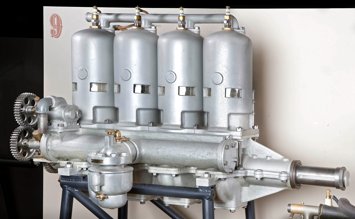
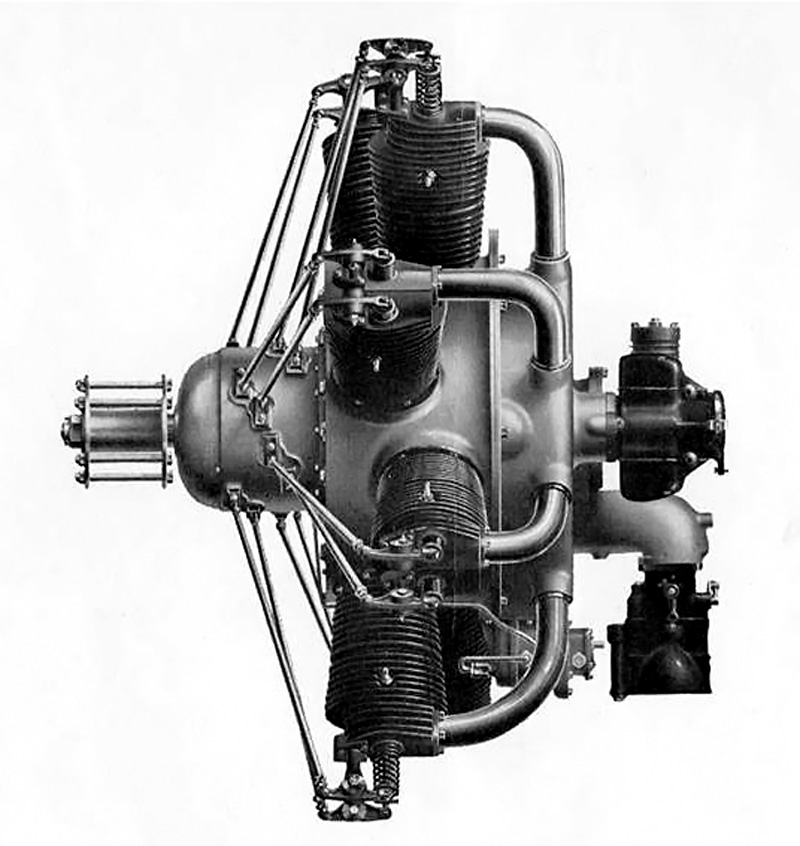
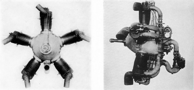
A four-cylinder Roberts 4-X engine on display at the Smithsonian National Air and Space Museum in Washington, DC. Note the tubular housing to which the carburetor is attached. Inside the housing is the tubular distributor sleeve for delivering the air/fuel mixture to the cylinders. The water pump is mounted on the upper rear of the housing. (National Air and Space Museum image)

Roberts Motor Company’s aircraft engines differed from their marine counterparts in that they were engineered to be as light as possible. To keep parts (and associated points of failure) to a minimum, the Roberts two-stroke engines did not use poppet valves. In addition, Roberts’ engines incorporated unique designs to overcome drawbacks generally found with two-stroke engines, namely the air/fuel mixture pre-igniting as it entered the cylinder, causing a backfire.

The engines’ cast cylinder liners were constructed of a proprietary alloy called “Aerolite,” which Roberts said was as light as aluminum but twice as strong and had the wear properties of cast iron. The individual cylinder liners were covered by an aluminum water jacket. A ring around the base of the cylinder liner would fit into a recess around the bottom of the water jacket, securing the two together. The cylinder liner’s spark plug boss (and that of the decompressor if present) passed through the water jacket casting. The outer diameter of the boss was threaded, and a nut secured the top of the water jacket and cylinder liner. This nut would also draw up the base of the liner into the water jacket, securing the whole cylinder assembly.

Roberts 6-X engine side

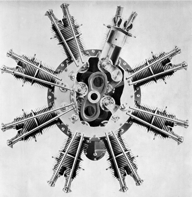
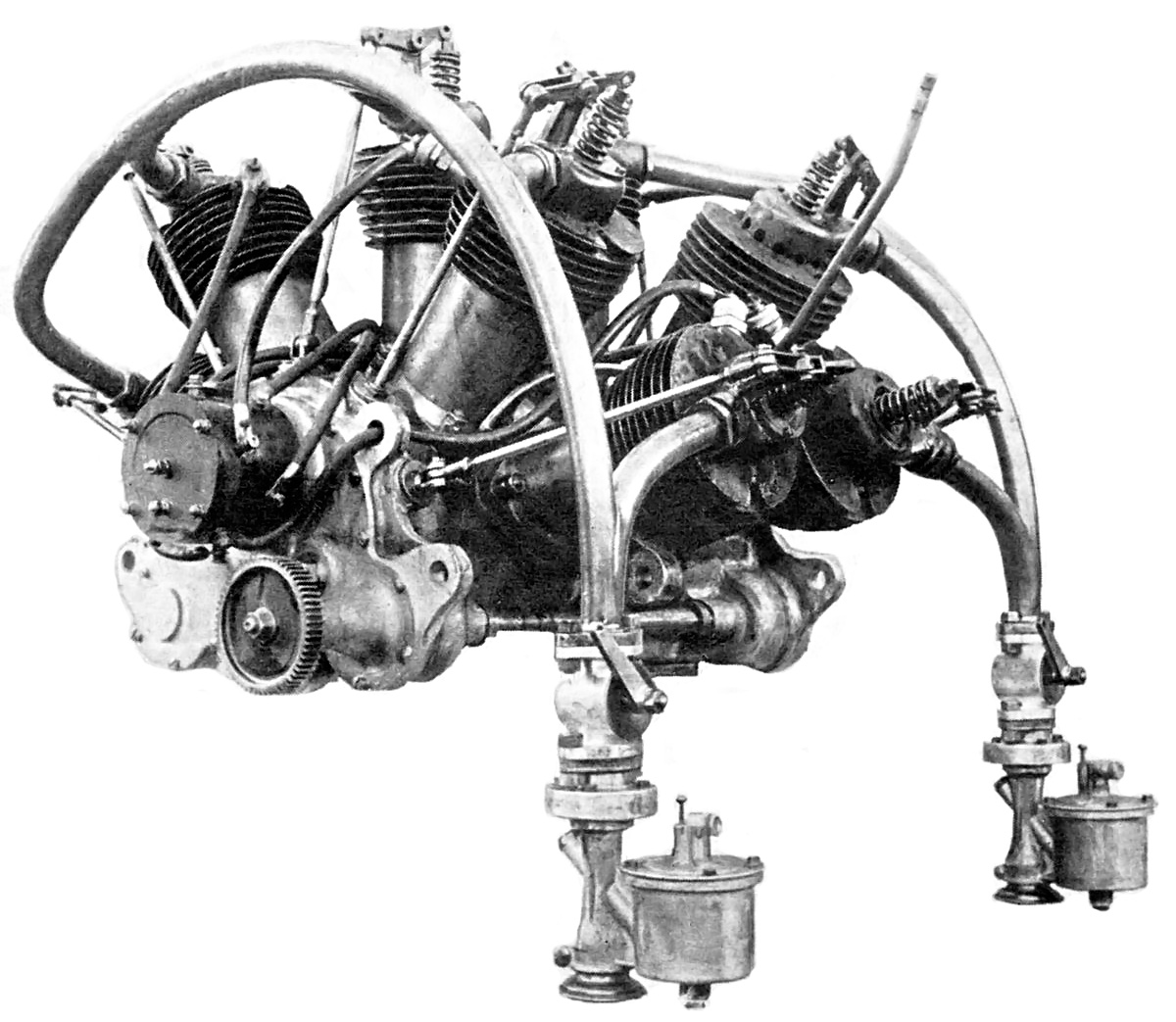
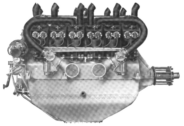
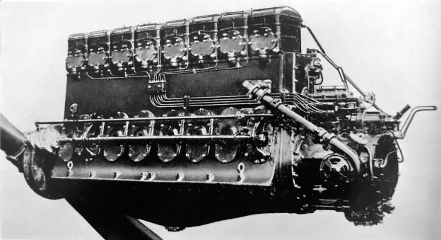
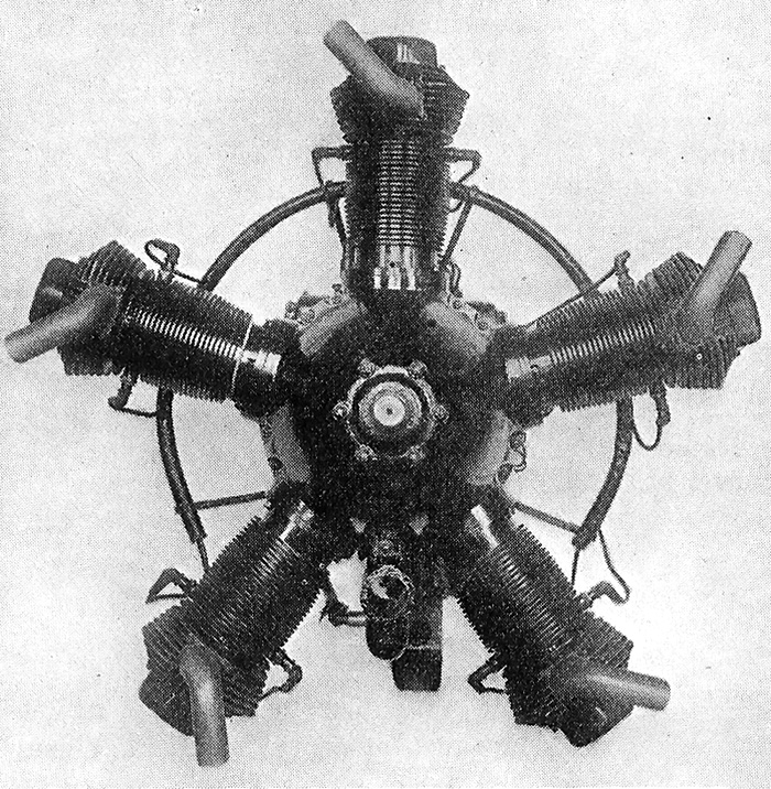
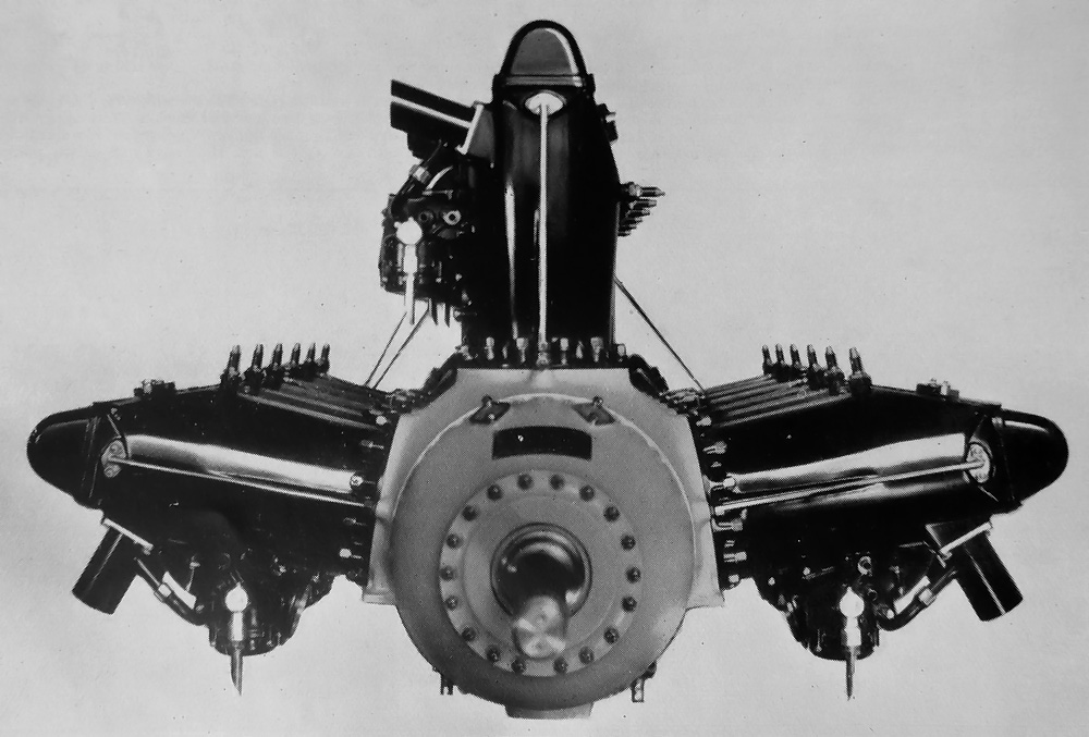
The six-cylinder Roberts 6-X engine. The crankcase casting provided a space under each cylinder for the air/fuel mixture. Each space was sealed by crankshaft main bearings. Note the two exhaust ports for each cylinder.

The pistons were made of cast iron and were attached to drop forged I-beam connecting rods made of vanadium steel. The connecting rods were attached to the crankshaft by a bronze strap about a third the size of the crankpin. (Firing every revolution, the pistons of a two-stroke engine are not pulled down by the crankshaft and therefore do not need a full-size connecting rod bearing cap.) The crankshaft was hollow and made of drop forged steel. The cylinders were secured to the crankcase by four bolts, with adjacent cylinders sharing their bolts. The crankcase was made from Magnalium, an aluminum and magnesium alloy that made it lighter and stronger than an aluminum crankcase of the same thickness.

The carburetors were mounted to a tubular housing that ran along the right side of the engine. Inside of this housing was a tubular distributor sleeve (also called a rotary induction valve) driven by an intermediate gear that engaged the accessory drive gear mounted on the end of the crankshaft. The distributor sleeve rotated at crankshaft speed and had ports to control the air/fuel mixture flow from the carburetor into the crankcase. The crankcase was constructed so that a small space existed under each cylinder for the incoming charge. The carburetor aligned with multiple ports in the distributor sleeve to allow a constant flow into the distributor, but each cylinder matched up with a single port to control air/fuel delivery. For each cylinder, the incoming charge passed from the distributor though a port in the side of the crankcase. The distributor helped eliminate the risk of backfires and distributed the air/fuel mixture equally to all the cylinders, allowing the engine to run smoothly.

Roberts 4-X Rotary Distributor

The tubular distributor sleeve of a Roberts 4-X engine. The ports at the center of the tube aligned with the carburetor.

The distributor port opened as the piston moved up and drew in the air/fuel mixture. The port then closed as the piston moved down on its power stroke, compressing the incoming charge underneath. Two ports in the piston aligned with ports in the cylinder wall when the piston was near bottom dead center. This alignment allowed the pressurized, incoming air/fuel mixture to flow from the crankcase into a space on the outer side of the cylinder. In this space, Roberts installed what they called a “cellular by-pass” to prevent backfires. The incoming charge flowed through the cellular by-pass and then through another set of ports positioned above the piston. The piston’s top had a large deflector to send the incoming air charge toward the top of the combustion chamber to improve exhaust gas scavenging. This deflector was positioned on the intake port side of the piston. Two exhaust ports were located on the opposite side of the cylinder from the intake ports and were also controlled by the piston so that all ports were uncovered when the piston was near bottom center.

The cellular by-pass was a series of flat and corrugated plates creating a honeycomb mesh. The large surface area of the cellular by-pass extinguished any flame should a backfire occur, but it did not decrease the engine’s efficiency in normal operation. The Roberts engine’s resistance to backfiring allowed a leaner mixture to be used, thus increasing the engine’s fuel economy. The cellular by-pass also helped mix and vaporize the fuel in the incoming charge.

Roberts 6-X parts Weeks

Various parts for one of the two Roberts 6-X replica engines built for Kermit Weeks. Note the deflector on the top of the pistons and the two ports in the side of the pistons. A decompressor valve can be seen on the top of the cylinder in the lower left corner. (Fantasy of Flight image)

The water pump was mounted at the right rear of the engine and was driven from the gear driving the tubular distributor sleeve. The pump drew water from the radiator and then pushed it through a passageway on the right side of the crankcase. Each cylinder had an open port that aligned with a coolant passageway in the crankcase. The water flowed into a small channel in the cylinder and then around the exhaust ports and up into the cylinder’s water jacket. It then flowed out the top of the cylinder and into a manifold that led back to the radiator. The engine was lubricated by the oil and fuel mixing and via splash lubrication. Grease cups were used to lubricate the main bearings.

A single spark plug was mounted in the center of each cylinder’s semi-hemispherical combustion chamber. The spark plug was fired by a Bosch magneto mounted at the rear of the engine. The magneto was driven by a helical gear via the intermediate gear that meshed with the accessory drive gear on the end of the crankshaft. An advance fork mounted above the magneto shaft moved the helical gear of the magneto along its shaft to either advance or delay ignition—an adjustment that could be made by the pilot while in flight.

Roberts 6-X gears Weeks

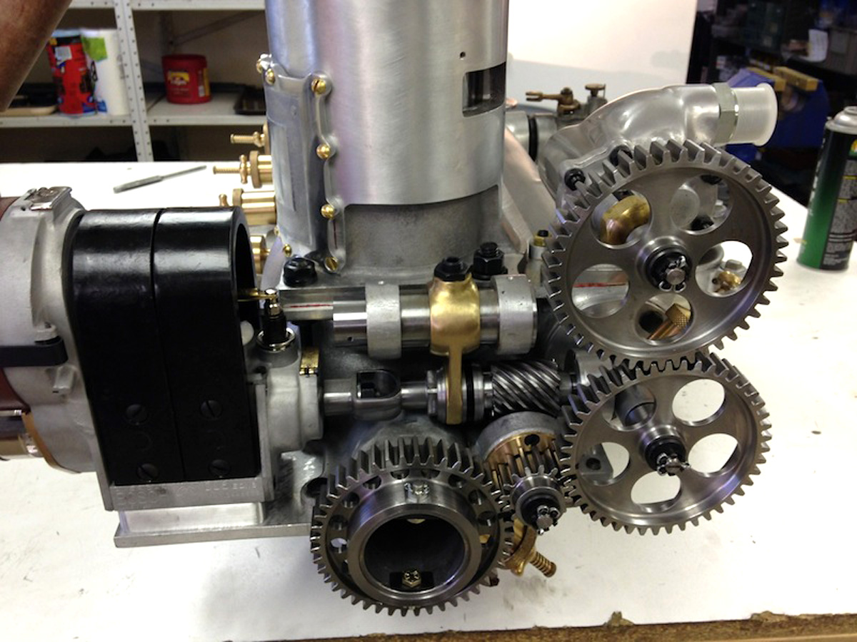
The exposed accessory gears of the Robert 6-X replica. The crankshaft drove an intermediate gear, the backside of which engaged the magneto drive shaft. To advance or delay the timing, the helical gear for the magneto drive shaft could be adjusted by the brass advance fork above it. The intermediate gear drove the gear for the tubular distribution sleeve, which in turn drove the gear for the water pump. (Fantasy of Flight image)

The Roberts four-cylinder engine was known as the 4-X. It had a 4.5 in (114 mm) bore, a 5 in (127 mm) stroke, and a total displacement of 318 cu in (5.2 L). The engine produced 50 hp (37 kW) at 1,200 rpm. It used one carburetor, and its magneto turned at twice crankshaft speed. Its crankshaft was 2.5 in (64 mm) in diameter, with crankpins 1.75 in (44 mm) in diameter and 2.5 in (64 mm) long. The crankshaft was supported by five main bearings; the one toward the propeller was 6.375 in (162 mm) long. The crankshaft was 40 in (1,016 mm) long and weighed 17.5 lb (7.9 kg). The 4-X was 40.5 in (1.03 m) long, 25 in (.64 m) tall, 24 in (.61 m) wide, and weighed 170 lb (77 kg).

The six-cylinder engine was known as the 6-X. Like the 4-X, it had a 4.5 in (114 mm) bore and a 5 in (127 mm) stroke. The engine’s total displacement was 477 cu in (7.8 L), and it produced 75 hp (56 kW) at 1,200 rpm. The 6-X used two carburetors, and its magneto turned at three times crankshaft speed. Its crankshaft and crankpins were the same size as the 4-X’s. The crankshaft was supported by seven main bearings, was 52 in (1,321 mm) long, and weighed 27.5 lb (12.5 kg). The 6-X was 52.5 in (1.33 m) long, 25 in (.64 m) tall, 24 in (.60 m) wide, and weighed 240 lb (109 kg).

Roberts 6-XX engine

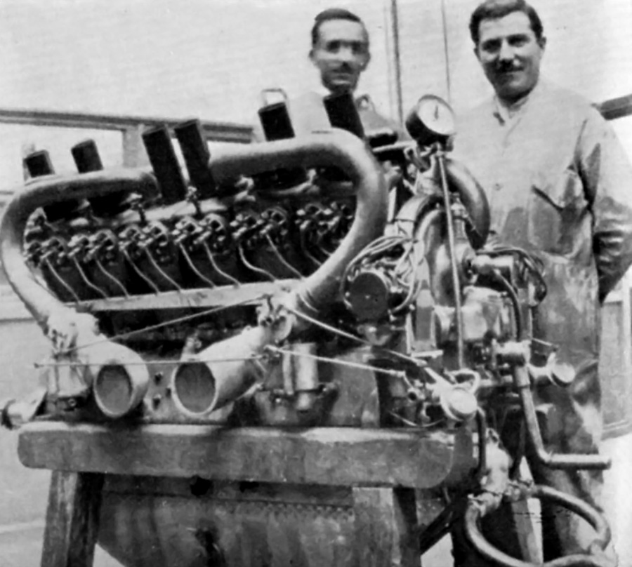
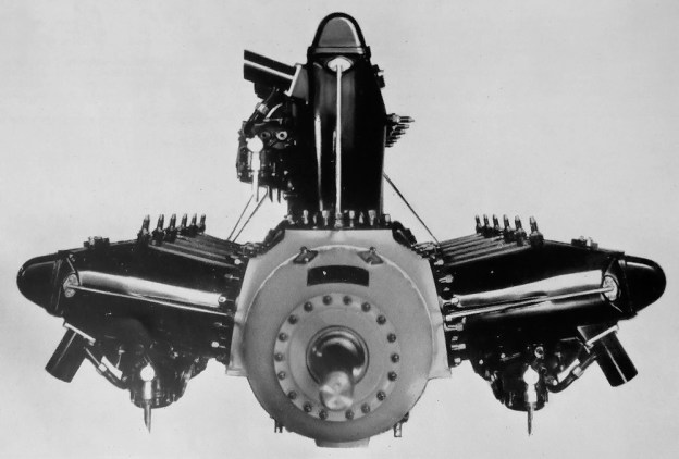
The Roberts 6-XX engine with exhaust manifolds and enclosed accessory gears.

A further development of the six-cylinder engine was the 6-XX. This engine had its accessory gears covered and bathed in oil. Its bore and stroke were enlarged to 5.5 in (140 mm) and 6 in (152 mm) respectively. The 6-XX’s total displacement was 588 cu in (14.0 L), and it produced 125 hp (93 kW) at 1,100 rpm. The engine used two carburetors. Its Bosch HL magneto turned at 1.5 times crankshaft speed to fire one of the two spark plugs in each cylinder. The other spark plug was fired by a Delco distributor. The 6-XX’s crankshaft was 3 in (76 mm) in diameter, with crankpins 2.5 in (64 mm) in diameter and 3.5 in (99 mm) long. The crankshaft was supported by seven main bearings; the one toward the propeller was 12 in (305 mm) long. The 6-XX was approximately 60.5 in (1.54 m) long, 27.5 in (.70 m) tall, 24 in (.60 m) wide, and weighed 390 lb (177 kg).

The Roberts engines were refined over time and used by a good number of early aviation pioneers. By 1913, all Roberts engines had the exposed accessory gears enclosed like those on the 6-XX engine. This change necessitated the magneto be repositioned. The cylinder liners were now made of cast iron, and the water jackets were made of Aerolite. The pistons were also made of Aerolite, which reduced their weight by over 2 lb (.9 kg) each. The tubular distributor sleeve was mounted on four sets of ball bearings to reduce friction. Dual ignition, like that used on the 6-XX, was available as an option on the 6-X engine. A starting crank attached to the end of the crankshaft was also an option.

Roberts 6-X 1913 rear

The rear of the 1913 Roberts 6-X engine showing the enclosed accessory gears, repositioned magneto, and optional hand starting crank on the end of the engine. The decompressors can be seen on the top of the cylinders. These were used to make starting the engine easier.

As two-stroke Roberts engines were surpassed by new four-stroke engines, like the Curtiss OX-5 and Hispano-Suiza 8, the company struggled to keep up. By 1918, the 6-X engine had its bore and stroke increased to 5 in (127 mm) and 5.5 in (140 mm) respectively, giving a total displacement of 648 cu in (10.6 L). The tubular distributor was replaced by more conventional intake manifolds, and the engine produced 100 hp (75 kW) at 1,200 rpm. The 6-X now weighed 368 lb (167 kg).

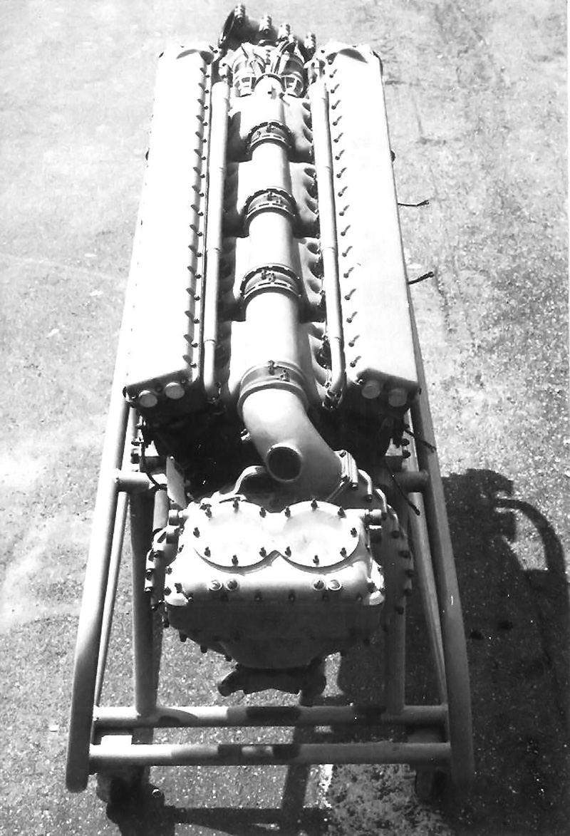
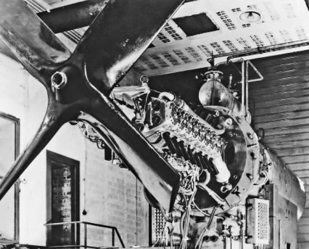
There is also some indication that a V-12 was planned and possibly constructed by Roberts in the late 1910s. This engine was known as the E-12. It had a 6 in (152 mm) bore, a 6.5 in (165 mm) stroke, and a total displacement of 2,205 cu in (36 L). The engine produced 350 hp (261 kW) at 1,200 rpm. Each cylinder had its own crankpin, and 13 main bearings supported the crankshaft. The E-12 weighed 990 lb (490 kg).

Roberts 6-X Weeks

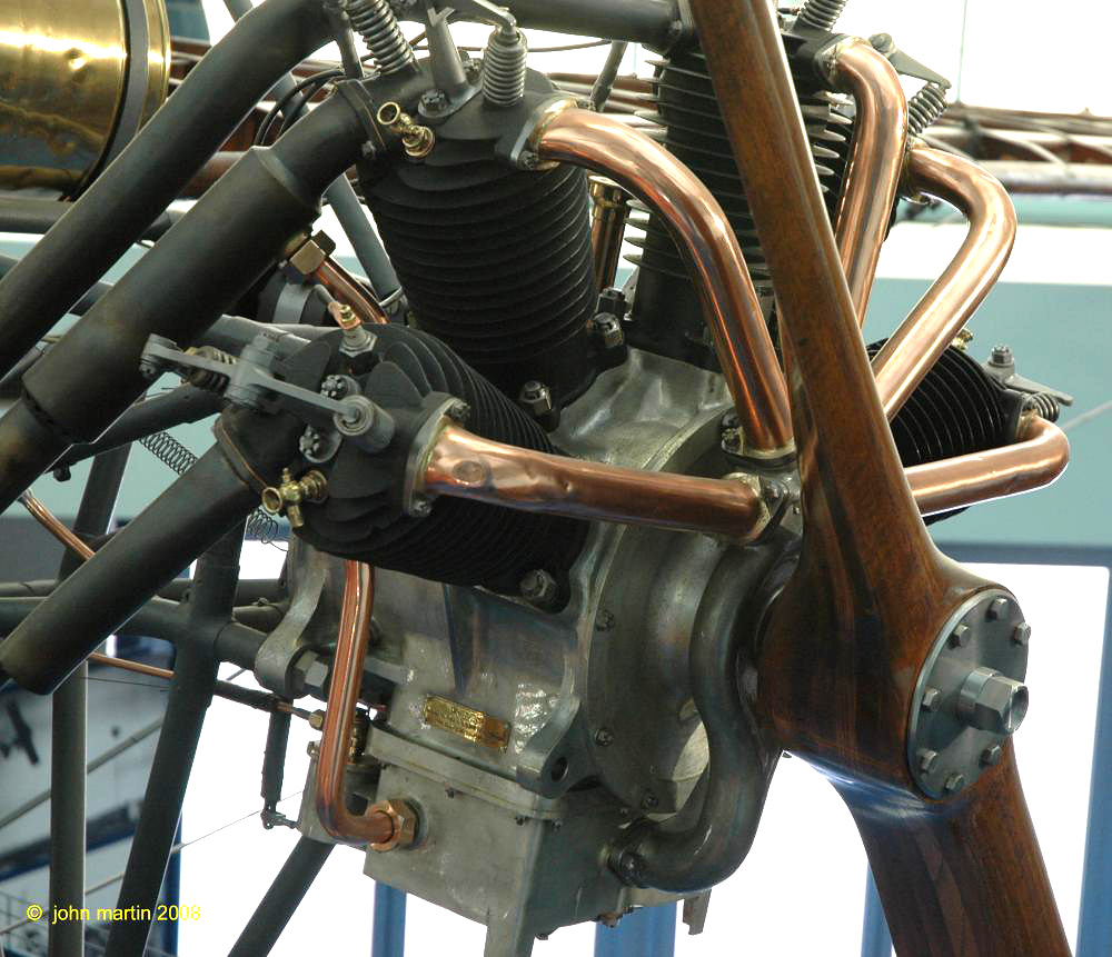
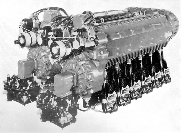
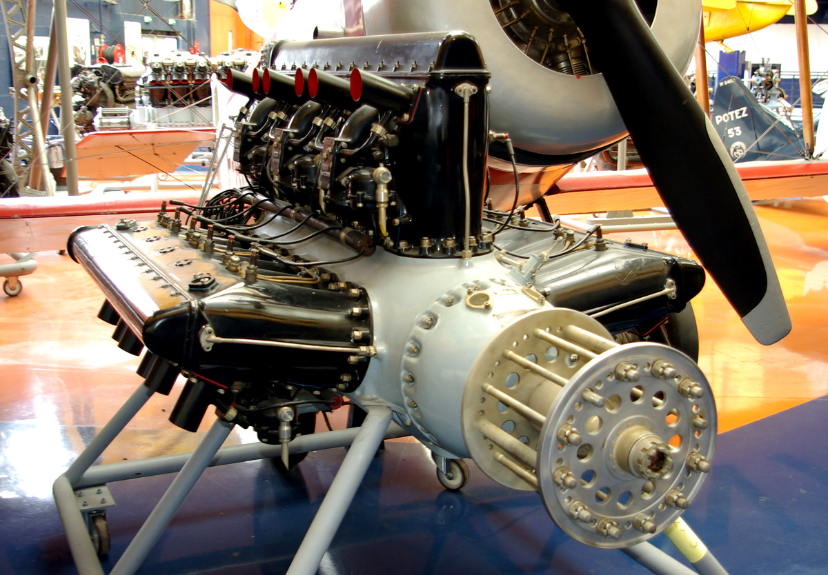
One of Weeks’ Roberts 6-X replica engines. The engines were built to power a replica Benoist XIV flying boat. The Benoist is a pusher, which is why the outlet for the coolant pipe is toward the propeller shaft. Note the brass grease cups for lubricating the crankshaft main bearings. The cover on each cylinder is for the cellular by-pass. (Fantasy of Flight image)

The Roberts Motor Company left the aviation field by 1919 to focus on marine engines. Around this time, the company changed its name to Roberts Motors. A few years later, Roberts Motors went out of business. A number of early Roberts four- and six-cylinder aircraft engines still exist in museums.

Recently, Kermit Weeks of Fantasy of Flight in Polk City, Florida commissioned the creation of two replica Roberts 6-X engines. One of the engines was a test engine, and the other would be installed in a Benosit XIV flying boat replica. An original engine was reverse engineered, allowing these engines to be built. Below is a video from 2013 of Mr. Weeks checking on the progress of the Roberts 6-X engine construction at Vintage & Auto Rebuilds in Chardon, Ohio. Both Roberts 6-X replica engines have since been completed and test run.


Sources:
Roberts Aviation Motors by The Roberts Motor Co. (1912)
– “Construction of Cylinder of Internal Combustion Engines” US patent 1,210,537 by Edmund W. Roberts (granted 2 January 1917)
The 1913 Model 6-X by The Roberts Motor Co. (1913)
Fantasy of Flight Blog (various entries relating to the Roberts engine and Benoist flying boat replica)
Aerosphere 1939 by Glenn Angle (1940)
(Jane’s) All the World’s Aircraft 1918 by C. G. Grey (1918)

Marchetti MP Cam Action

Marchetti Cam-Action Engines

By William Pearce

Paul J. Marchetti was born in Italy in 1889. In his adolescence, he became interested in machines, engineering, and aircraft. In 1910, when he was 21 years old, Marchetti emigrated from Lucca, Italy to the United States in search of greater opportunities. He worked his way west and supported himself as a logger, all the while dreaming of entering the aviation business.

Marchetti MP Cam Action side

The Marchetti eight-cylinder, cam-action aircraft engine of 1927. Note the stagger of the front and rear cylinders.

Unfortunately, there is little information about Marchetti, his life, and his inventions. By 1922, he was working with Henry A. Nordwick in Stockton, California. Nordwick was working on designing a radial engine in which the crank throw was replaced by a cam with four lobes. A roller on the big end of the connecting rod made contact with the cam, its points creating the piston strokes. Another Nordwick and Marchetti engine design dating from 1923 had the big end of each connecting rod attached to its own crank, which was geared to a main central gear.

By 1924, Marchetti was in San Francisco, California and filed a patent of his own for a broad-arrow engine using either a three- or four-lobe cam in place of the crankshaft. Still working with Nordwick, another patent was filed for an eight-cylinder radial with a two-lobe cam. A lever extended from the big end of each connecting rod and was attached to the crankcase. Also connected to this lever was an auxiliary piston. Fed by pressurized air, the auxiliary piston forced the connecting rod to be in contact with the cam at all times. One auxiliary piston was positioned between each main piston.

Nordwick Marchetti cam engine patents

Drawings from Nordwick and Marchetti cam engine patents. The patent for the four-lobe cam design (left) was filed in 1922, and the patent for the eight-cylinder engine with auxiliary pistons (right) was filed in 1924.

Nordwick and Marchetti focused on inline engines in 1925. They designed a two-lobe cam engine, again using a lever extending from the big end of the connecting rod to the crankcase. That same year, Marchetti patented an inline engine under his business name: Marchetti Motor Patents. For this engine, the crankshaft throws were replaced with disks, offset to the crankshaft’s centerline. A connecting rod ran in a grove in each disk, and the disk’s offset would create the up and down strokes for the piston. The circular disk could also be substituted in favor of a lobed design for increased engine performance.

In 1926, Marchetti took out a patent on an inline engine with a two-lobe cam driving the pistons. The connecting rods were paired together via a rocker so that when one piston was at top dead center the other piston would be at bottom dead center. This configuration was also suggested for a U engine with two separate cam (crank) shafts.

Marchetti Motor Patents

Drawings from the Marchetti cam engine patents. The 1924 broad-arrow engine design is on the left, and the 1925 inline cam disk design is on the right.

1927 saw Marchetti focus on the business side of his dreams. His company, Marchetti Motor Patents, Inc., was officially formed with $2,000,000 of capital and operated out of the newly completed Russ Building, the tallest building in San Francisco until 1964. Marchetti worked on new engines and aircraft. In 1928, ground was broken for the Marchetti Motor Patents factory at Mills Field (now San Francisco International Airport). The factory had an expected output of 100 aircraft and 1,000 engines per year.

With his business established, Marchetti designed and built a new cam engine. While incorporating some aspects of the previous engine designs, this engine also had some unique features that are not found in any of the patents filed by Marchetti. However, the connecting rod arrangement and cam were similar to those found in a patent filed solely by Nordwick in 1926.

Marchetti MP info

Marchetti Motor Patents Inc. advertisement from 1929.

The new engine was an air-cooled, eight-cylinder radial. The cylinders were slightly staggered, making two rows of four cylinders. Twin two-lobe cams replaced the conventional crankshaft. Via roller bearings, the front cam actuated the connecting rods for the front cylinders, and the rear cam actuated the connecting rods for the rear cylinders. One fore and one aft cylinder were paired together by a common bell crank attached to the big end of the connecting rods. The center of this bell crank was the pivot point and was attached to the crankcase. The cams were staggered so that when one of the paired cylinders was at top dead center, the other cylinder was at bottom dead center. Since each cam had two lobes, there would be four piston strokes (or one power stroke) for each revolution. Marchetti referred to this design as a “cam-action” engine.

Each of the engine’s cylinders had one intake and one exhaust valve at the center of its head. The valves were actuated by pushrods driven at the front of the engine. Two spark plugs were located just below the valves of each cylinder and were fired by a magneto driven from the rear of the engine. A carburetor attached to the lower rear of the engine fed the air/fuel charge into a blower (weak supercharger). The blower helped mix the air/fuel charge, which was then distributed to the cylinder via separate manifolds. The engine had a 4.0 in (102 mm) bore, a 4.25 in (108 mm) stroke, and a total displacement of 427 cu in (7.0 L). Initially, 135 hp (101 kW) was expected from the engine, but 160 hp (119 kW) was achieved after testing. The engine weighed 350 lb (159 kg).

Marchetti MP Cam Action

Cutaway view of the Marchetti cam-action engine. The rear cam can barely be seen in the rear of the crankcase. Note how each cam actuates one “row” of cylinders. The bell crank for the upper right cylinder pair can be seen clearly. The bell crank attached to the connecting rods and pivoted in the middle, where it was mounted to the crankcase.

The eight-cylinder engine was first run in 1927. Most sources say only one engine was built, but some claim more were built. The engine passed a 400 hour maximum load test, and 2,200 hours were accumulated with no apparent signs of wear. Marchetti modified a Cessna AW for flight testing the eight-cylinder radial, but it is not known if the engine was ever installed. This aircraft was designated Marchetti M-I

Marchetti MP M-II Arrow advert

Advertisement from September 1929 for the Marchetti M-II Arrow and its four-cylinder engine cam-action engine.

Another Marchetti aircraft was the M-II Arrow—a two-place monoplane to be powered by a Marchetti inline, four-cylinder, air-cooled, cam-action engine of 100 hp (75 kW). The M-II was constructed of wood covered by fabric. On the drawing board was the Marchetti M-III—an eight passenger, all metal aircraft intended for passenger service. It was to be powered by two Marchetti eight-cylinder cam-action radials.

With his aircraft and aircraft engine manufacturing plans underway, Marchetti continued to chase his dream of becoming a pilot. On 31 August 1929, one week before the plant opened, Marchetti took off from Mills Field to look over his nearly finished factory and log some of the two hours remaining before he could get his pilot’s license. He flew into a fog bank, and what happened next is not known. A short time later, Marchetti’s aircraft was seen falling from under the fog bank in an inverted flat spin. The aircraft crashed half a mile (.8 km) from shore into San Francisco Bay. Rescue boats reached the scene as fast as possible, but it was too late. Marchetti’s body was found in the submerged fuselage.

The Marchetti M-II Arrow was completed and flown, but it is not known which engine powered it. While it is possible that it flew with a Marchetti inline cam engine, it is more likely that another four-cylinder engine was installed. Marchetti’s grand aviation plans drifted into oblivion after his death. Marchetti Engine Patents Inc. was sold to William Rider and then resold to United Aircraft Sales where it faded to obscurity. What happened to the M-I, M-II Arrow, or any of the cam-action test engines is not known. It is believed that the M-III transport never progressed beyond the design phase.

Marchetti MP M-II Arrow

The complete Marchetti M-II Arrow with its unidentified engine. The aircraft carried the registration X-98M. (Frank Rezich image via www.aerofiles.com)

Sources:
– “Falls to Death: Paul Marchetti” Oakland Tribune (1 September 1929)
– “Marchetti Motor to Revolutionize Airplane Industry” Ukiah Dispatch Democrat (12 May 1928)
– “The Business of Building Aircraft” San Francisco Business (11 September 1929)
– “Internal Combustion Engine” US patent 1,374,164 by H. A. Nordwick (granted 5 April 1921)
– “Internal Combustion Engine” US patent 1,528,164 by H. A. Nordwick (granted 3 March 1925)
– “Internal Combustion Motor” US patent 1,538,208 by H. A. Nordwick et al (19 May 1925)
– “Engine” US patent 1,654,378 by P. Marchetti (granted 27 December 1927)
– “Internal Combustion Engine” US patent 1,597,474 by H. A. Nordwick et al (granted 24 August 1926)
– “Internal Combustion Engine” US patent 1,624,277 by H. A. Nordwick et al (granted 12 April 1927)
– “Internal Combustion Motor” US patent 1,667,213 by P. Marchetti (granted 24 April 1928)
– “Motor” US patent 1,624,269 by P. Marchetti (granted 12 April 1927)
– “Duplex Cam Motor” US patent 1,630,273 by H. A. Nordwick (granted 31 May 1927)
Aerosphere 1939 by Glenn Angle (1940)
http://www.aerofiles.com/_ma.html

REP 7-cylinder

R.E.P. Fan (Semi-Radial) Aircraft Engines

By William Pearce

Robert Esnault-Pelterie was born in France on 8 November 1881. In the early 1900s, he began experimenting with a glider modeled after the Wright Brothers’ glider of 1902. Esnault-Pelterie had experienced trouble with the Wrights’ wing warping technique and switched to ailerons in 1903. In 1906, Esnault-Pelterie began constructing a powered aircraft of his own design as well as an engine to power it. Esnault-Pelterie named the aircraft the R.E.P. 1 and it first flew in 1907. A new feature of the aircraft was a control stick, which Esnault-Pelterie patented. That patent made Esnault-Pelterie a rich man once royalties were paid after World War I. While the unique engine that he designed was the first in a family of engines known as R.E.P., their success would not endure like that of the control stick.

REP 7-cylinder

Front view of the R.E.P. seven-cylinder fan engine. Exhaust gases flowed out the holes around the top of the cylinders. The intake manifold can barely be seen behind the cylinders. In this view, the four cylinders on the right shared an intake manifold as did the three cylinder on the left.

Esnault-Pelterie’s first engine was an air-cooled, seven-cylinder fan engine. Sometimes referred to as a semi-radial, this engine had cylinders that were fanned-out on the top of the crankcase and not positioned around its entirety like a true radial. The cylinders were arranged in two rows—the front had four cylinders, and the rear had three cylinders. This configuration solved lower cylinder lubrication issues of radial engines, and air-cooling issues of inline engines.

The cast iron cylinders were attached to an aluminum crankcase. The upper part of the cylinder had cooling fins to dissipate heat. At the very top of the cylinder was a large, single valve. The valve was shaped like a piston and inverted, with the valve stem attached to underside of the head. When the valve was completely closed, a flange on its head would seat against the cylinder head and seal the cylinder. When the valve was partially open, exhaust gases flowed around the flange and escaped through ports in the cylinder head. When the valve was completely open, ports in its sides aligned with ports in the cylinder head to allow the intake mixture to flow into the cylinder.

REP 7-cylinder section

In this section view of the R.E.P. seven-cylinder engine, the cylinders are numbered by firing order. Cylinder 5 has the intake/exhaust valve completely closed. Cylinder 1 shows the valve partially open to allow exhaust gases to exit the cylinder. Cylinder 2 shows the valve completely open to allow the air/fuel mixture into the cylinder. Note the master/articulated connecting rod arrangement.

The valve was actuated by a rocker arm attached to the cylinder. The rocker arm was moved via a pushrod that was operated by a cam ring inside the engine. Each row of cylinders had its own cam ring positioned at the rear of the engine, and the cam rings had stepped lifts. The first step opened the valve part way to allow the exhaust gases to vacate the cylinder. The second, higher lift completely opened the valve to allow the fresh air/fuel mixture into the cylinder. For the intake, the cylinders were separated into left and right groups, with the left group (when viewing the engine from the rear) having an additional cylinder. Each group shared a common intake manifold with a carburetor attached to its end. The intake manifold was attached to the upper rear of the cylinder. Exhaust gases flowed out though ten holes around the cylinder’s top; there were no exhaust stacks.

A single spark plug was installed in the side of the cylinder and fired by an ignition coil powered by a battery. The pistons were made of steel and had two oil rings. They were attached to the connecting rods by trunnions bolted to the underside of the piston. The connecting rod for each row of cylinders had one master rod, and the rest were articulating rods. The crankshaft had two throws offset 180 degrees and was supported by two main bearings. To balance the crankshaft, Esnault-Pelterie left the crankpin solid for the row with an additional cylinder, and the crankpin for the row with one fewer cylinder was drilled hollow.

REP 10-cylinder side

This side view of the R.E.P. 10-cylinder engine illustrates how it was comprised of two five-cylinder engines bolted front-to-front. Note the rocker arm arrangement and the single valve. The pictured engine was equipped with magnetos.

The engine had a 3.35 in (85 mm) bore and 3.74 in (95 mm) stroke. The seven cylinders displaced a total of 230 cu in (3.8 L). The engine produced 30 hp (22 kW) at 1,500 rpm and weighed 150 lb (68 kg). A five-cylinder version was also built with three cylinders in the first row and two in the second. It produced 20 hp (15 kW) at 1,500 rpm from its 164 cu in (2.7 L) and weighed 118 lb (54 kg). Another version consisted of two five-cylinder engines joined at their front to create a 10-cylinder engine. Each engine group had its own intake manifold feeding five cylinders. The 10-cylinder engine produced 50 hp (37 kW) at 1,500 rpm from its 329 cu in (5.4 L) and weighed 214 lb (97 kg). Some sources indicate the same coupling treatment was applied to the seven-cylinder engine to create a 14-cylinder engine, but this cannot be confirmed. A 14-cylinder engine would have displaced 461 cu in (7.5 L) and produced around 70 hp (52 kW).

The five- and seven-cylinder engines powered a number of early aircraft (R.E.P.s, Bléroits, Kapferer-Paulhans, and Breguets), but it is unlikely the 10-cylinder engine ever flew. Esnault-Pelterie received an award in 1908 from the Société des ingénieurs civils de France (Society of Civil Engineers of France) for his seven-cylinder R.E.P. engine. However, the cylinder’s single valve proved unsatisfactory, and the engines were redesigned in 1909.

REP 10-cylinder back

Rear view of the R.E.P. 10-cylinder engine equipped with a coil ignition. Note that each engine section has its own intake manifold and carburetor.

The updated engines had two valves per cylinder, but they were still operated by a single rocker arm. The intake valve was in the front of the cylinder, and the exhaust valve was in the rear. The rocker arm pivoted between the valves so that it pushed the intake valve open and then rocked back to pull down on the exhaust valve to open it. This was achieved by a grooved cam-disc that could “pull” and “push” the pushrod.

The engine’s bore and stroke were increased to 3.94 in (100 mm) and 5.51 in (140 mm). The five-cylinder engine displaced 335 cu in (5.5 L) and produced 60 hp (45 kW) at 1,400 rpm. The seven-cylinder engine displaced 470 cu in (7.7 L) and produced 90 hp (67 kW) at 1,400 rpm. There is no indication that any attempt to couple the engines was made. The cylinders had revised cooling fins, and the spark plug was repositioned to the cylinder head. Magnetos were used in place of the coil ignition.

REP 5-cylinder Type D

An updated R.E.P. five-cylinder engine preserved in a R.E.P. Type D monoplane at the Musée de l’Air et de l’Espace. Note the two valves per cylinder and rocker arm arrangement. The unique induction system can be seen in which it drew air from the crankcase and delivered it to the cylinders via the copper pipes. The individual exhaust pipes can be seen at the rear of the engine. (John Martin image via the Aircraft Engine Historical Society)

Induction and exhaust were also updated. Intake air was fed from the crankcase (where it was warmed), through a distributor, and then to the front of each cylinder. Exhaust gases were collected in pipes at the rear of each cylinder and directed away from the cockpit. The many changes increased the weight of the engines to 243 lb (110 kg) for the five-cylinder and 287 lb (130 kg) for the seven-cylinder. The updated R.E.P. fan engine had no trouble running for 10 hours non-stop during various bench tests.

The five-cylinder engine seemed the more successful of the two and was installed in a number of aircraft (R.E.P.s and Farman-Neubauers). It was used in the Vickers R.E.P., which was the first aircraft made by Vickers and would have been the first aircraft to fly in Antarctica had its wings not been damaged during a demonstration flight in Australia. Even so, the wingless Vickers was taken to Antarctica and used as a powered sled, but with not much success. The remains of this aircraft were rediscovered there in January 2010.

Vickers REP in Antarctica

The Vickers R.E.P. in Antarctica in 1911. The engine clearly has two valves per cylinder and the unique induction system of the updated fan engine.

In 1911, Esnault-Pelterie refocused his design efforts on true radial engines, constructing five- and seven-cylinder engines. The fan/semi-radial engines were phased out in 1912. Over the next few years, Esnault-Pelterie stopped designing piston engines as he became more interested in rocketry. A few R.E.P. fan engines still exist in museums, including a seven-cylinder engine in Esnault-Pelterie’s original R.E.P. 1 aircraft from 1907 displayed at the Musée national des Arts et Métiers (National Museum of Arts and Crafts) in Paris, France. This museum may also hold another original seven-cylinder engine cutaway. An updated five-cylinder engine exists installed in an uncovered R.E.P. Type D monoplane from 1910 at the Musée de l’Air et de l’Espace (Air and Space Museum) in Le Bourget, France.

Note: Many sources list a variety of different bore and stroke combinations for the R.E.P. fan engines. Some sources list some of the early engines as having a 3.54 in (90 mm) stroke, while others list the updated engines as having a 4.33 in (110 mm) bore or 6.30 in (160 mm) stroke. While it is possible that such bore and stroke combinations were built, little supporting information has been found.

REP 1 with 7-cylinder engine

Esnault-Pelterie’s original R.E.P. 1 aircraft and its engine preserved in the Musée national des Arts et Métiers. (PHGCOM image via Wikimedia Commons)

Sources:
– “Moteur Extra-Léger a Explosion” by Robert Esnault-Pelterie, Mémoires et Compte Rendu des Travaux de la Société des ingénieurs civils de France Bulletin (December 1907)
Les aéroplanes et moteurs R.E.P. by Gérard Hartmann (4 MB pdf)
Les Moteurs a Pistons Aeronautiques Francais Tome I by Alfred Bodemer and Robert Laugier (1987)
– “The First Paris Aeronautical Salon: Engines for Aeroplanes” Flight (16 and 23 January 1909)
Aero Engines by G. A. Burls (1916)
http://aviatechno.net/bib/001n_les_moteurs_aviation.php
http://www.nmspacemuseum.org/halloffame/detail.php?id=7
http://en.wikipedia.org/wiki/Vickers_R.E.P._Type_Monoplane

FIAT AS8 V-16 side

FIAT AS.8 Engine and CMASA CS.15 Racer

By William Pearce

Since 10 April 1933, Italy had enjoyed ownership of the 3 km absolute world speed record for aircraft. Warrant Officer Francesco Agello set the record at 423.824 mph (682.078 km/h) in the Macchi-Castodi MC.72 seaplane built for the Schneider Trophy Contest. The MC.72 was powered by a 24-cyllinder FIAT AS.6 engine. Agello went on to raise the record to 440.682 mph (709.209 km/h) on 23 October 1934 in another MC.72.

FIAT AS8 V-16 side

Side view of the FIAT AS.8 V-16 engine specifically designed for the CMASA CS.15 racer.

However, Germany captured the world speed record on 30 March 1939, when Hans Dieterle flew 463.919 mph (746.606 km/h) in the Heinkel He 100 (V8). Germany raised the record a month later on 26 April 1939, when Fritz Wendel traveled 469.221 mph (755.138 km/h) in the Messerschmitt Me 209 (V1).

Even before Dieterle’s record flight, the Italians had considered building an aircraft specifically for a new record attempt. FIAT, with the support of the Italian government, wanted to win the record back and had initiated an aircraft and engine design that was somewhat finalized before Wendel’s record flight. The new record aircraft was designed and built by Costruzioni Meccaniche Aeronautiche SA (CMASA), a FIAT subsidiary in Pisa. The engine would be designed and built at FIAT’s headquarters in Turin.

FIAT AS8 rear

A rear view of the FIAT AS.8 showing the valley between the engine’s banks. The small manifolds on each bank are to take the cooling water from the cylinders. They are installed backward in this photo; the outlet should be at the engine’s rear. The long intake manifold is reminiscent of the even-longer manifold used on the AS.6. The large port in the manifold elbow, seen just above the carburetor, is a relief valve to prevent over pressurization of the manifold (perhaps in the event of a backfire—a major issue in the early development of the AS.6).

The aircraft was designed by Manlio Stiavelli and was known as the Corsa (meaning Race) Stiavelli 15, or just CS.15. Lucio Lazzarino, an engineer at CMASA, analyzed and tested various aspects of the CS.15 design. The CS.15 was a small, mid-wing, all-metal aircraft with a very low frontal area. Its 29.5 ft (9.0 m) monospar wing had conventional flaps and ailerons. The cockpit was situated far aft on the 29.2 ft (8.91 m) fuselage and was faired into the long tail.

To keep the wing thin and the fuselage narrow, the main wheels of the CS.15 folded toward each other before retracting aft into the fuselage. The CS.15’s fuel tank was situated behind the engine, in front of the cockpit, and above the main landing gear well. Fuel capacity was very limited, and the CS.15 was only meant to have enough endurance to capture the speed record—about 30 minutes of flight time. The estimated empty weight of the CS.15 was 4,213 lb (1,910) kg, and its total weight was 5,000 lb (2,270 kg).

To power the CS.15, Antonio Fessia and Carlo Bona laid out the AS.8 (Aviazione Spinto 8) engine design at FIAT. The AS.8 was a completely new design but had many common elements with the AS.6 engine used in the MC.72. The AS.6 was designed by Tranquillo Zerbi, and Fessia had taken over Zerbi’s position at FIAT when he passed away on 10 March 1939. The AS.8 was a liquid-cooled engine with cylinders very similar to the AS.6’s, utilizing two intake and two exhaust valves actuated by dual overhead camshafts. The AS.6 and AS.8 shared the same 5.51 in (140 mm) stroke, but the AS.8’s bore was increased .08 in (2 mm) to 5.51 in (140 mm). Reportedly, the AS.6 and AS.8 used the same connecting rods and both engines were started with compressed air.

FIAT AS8 front

This view displays the four magnetos of the FIAT AS.8 just above the propeller gear reduction. Note the the air distribution valves driven by the exhaust camshafts for starting the engine. The outlet of the water pumps can be seen in the forward position, which differs from the first image on this page.

The AS.8 was unusual in many ways. Its two banks of eight individual cylinders were set at 45 degrees. The 16 cylinders gave a total displacement of 2,104 cu in (34.5 L). The cylinders had a 6.5 to 1 compression ratio. The single-stage supercharger was geared to the rear of the engine and provided pressurized air to the cylinders via a long intake manifold between the cylinder banks. The carburetors were mounted above the supercharger. Unlike the AS.6, which used independent coaxial propellers, the AS.8 featured contra-rotating propellers geared to the front of the engine at a 0.60:1 reduction. Two sets of two-blade propellers 7.2 ft (2.2 m) in diameter could convert the AS.8’s power into thrust for the CS.15. The engine weighed 1,742 lb (790 kg).

Nine main bearings were used to support the long crankshaft and to alleviate torsional vibrations. In addition, drives for the camshafts, magnetos, and water pumps were mounted at the front of the engine. Each cylinder bank had two magnetos to fire the two spark plugs per cylinder. The distributor valve for the air starter was driven from the front of the exhaust camshaft for each cylinder bank. The exhaust gases of the AS.8 were utilized to add propulsive thrust through specially designed exhaust stacks on each cylinder.

FIAT AS8 bank

A detailed view of the AS.8’s right cylinder bank. Each cylinder had one spark plug on the outside of the engine and one in the Vee. The pipe next to the spark plug is for the air starter. The manifold at the bottom fed cool water into the cylinder jacket. (Emanuele image via Flickr)

For cooling, pressurized water was drawn into a pump on each side of the engine, near its front. A manifold delivered the water to each cylinder on the outside of the bank. The water then flowed through the cylinders and exited their top into another manifold situated in the Vee of the engine. The heated water, still under pressure, was taken back to the CS.15’s tail, where it was depressurized and allowed to boil. The steam then flowed through the CS.15’s wings, where 80% of their surface area was used to cool the steam and allow it to condense back into water. The water was then re-pressurized and fed back to the engine. Engine oil was also cooled by surface cooling in the rear and tail of the aircraft.

CMASA CS15

A three-view drawing of the CMASA CS.15 racer. Note the thin wings, minimal frontal area, and main gear retraction.

By early 1940, full-scale mockups of various CS.15 components were built and the construction of the CS.15 was underway. Wind tunnel tests indicated the CS.15 would reach a speed of 528 mph (850 km/h). The AS.8 engine was running on the test stand at this time. During these tests, the AS.8 achieved an output of 2,500 hp (1,864 kW), but the engine was rated at 2,250 hp (1,678 kW) at 3,200 rpm. The engine accumulated tens of hours running on the test stand and encountered few, if any, major failures. It is not known how many AS.8 engines were built, but the number is thought to be very small. The AS.8 was also the starting point of another V-16 engine, the FIAT A.38.

After Italy entered World War II in June 1940, progress on the CS.15 and AS.8 continued but at a much reduced pace. The CS.15 was damaged in various air raids, and it was further wrecked by the Germans as they exited Italy in late 1943. Some believe that whatever remained of the CS.15 was taken to Germany, as the aircraft essentially disappeared. As for the AS.8 engine, one example survived the war and is on display (or in storage) at the Centro Storico Fiat (Fiat Historic Center) in Turin, Italy.

The AS.8 achieved a power output greater than 1 hp/cu in and 1 hp/lb—accomplishments that were sought after by engine designers around the world.

Sources:
MC 72 & Coppa Schneider Vol. 2 by Igino Coggi (1984)
Aeronuatica Militare Museo Storico Catalogo Motori by Oscar Marchi (1980)
World Speed Record Aircraft by Ferdinand Kasmann (1990)
Italian Civil and Military Aircraft 1930-1945 by Jonathan W. Thompson (1963)

Lancia V-12 aircraft engine side

Lancia Tipo 4 and Tipo 5 V-12 Aircraft Engines

By William Pearce

Vincenzo Lancia was born near Turin, Italy in 1881. From an early age, he demonstrated an aptitude in mathematics, and his father encouraged him to become an accountant. However, Lancia was mainly interested in machinery and engineering. By the age of 17, he worked as a bookkeeper for a small bicycle and auto repair shop, operated by the Ceirano brothers. There, he became more of a mechanic’s assistant than a bookkeeper. When the shop built an automobile, FIAT bought the business and made Lancia, who was only 19, chief inspector of their new factory and also a test driver. His driving skills impressed FIAT, and they later made him a race car driver.

Lancia V-12 aircraft engine

The Lancia Tipo 4 V-12 aircraft engine displaying its individual cylinders and distinct valve train. The engine was configured for pusher installations, which is why exhaust was expelled toward the propeller.

But Lancia wanted to design. In 1906, at the age of 25, he and another FIAT worker founded their own car company: Lancia & Company. Lancia and his company produced a number of vehicles and engines and became known throughout Europe. Always experimenting and innovating, Lancia took out patents for a narrow Vee engine configuration and an offset crankshaft in 1915. World War I interrupted plans to use the design for an automotive engine but gave Lancia incentive to build an aircraft engine.

Known as the Tipo 4 (Type 4), the Lancia V-12 aircraft engine was water cooled and had a 50-degree angle between the cylinder banks. The engine’s individual steel cylinders were mounted to its aluminum crankcase, with a deep oil pan. Each cylinder had one intake and one exhaust valve perpendicular to the cylinder axis. These horizontal valves opened into a small, rectangular clearance space above the cylinders that extended the combustion chamber above the piston. The valves were actuated by long rocker arms positioned in the Vee of the engine. A single hollow camshaft positioned in the middle of the Vee acted upon the rocker arms. The camshaft was driven from the crankshaft at the rear of the engine. The valve train was very similar to that later used on the Duesenberg Model H aircraft engine.

Lancia V-12 aircraft engine stand

Two technicians stand next to the Tipo 4 engine. Note the straight exhaust stacks. This is thought to be the prototype Tipo 4, and it closely resembles the engine that is preserved in the FIAT/Lancia archives.

Each cylinder had two spark plugs that were positioned on the opposite side from the valves. Two magnetos were located at the rear of the engine, each firing one spark plug per cylinder. One of the magnetos could be replaced by a distributor. Two Claudel-Lancia carburetors were mounted on each side of the engine. Each carburetor supplied air to three cylinders via a manifold that looped above the cylinders. A section of the intake manifold was jacketed to use engine cooling water to heat the air/fuel mixture as it traveled to the cylinders. Exhaust was expelled via a short manifold extending above each cylinder.

The hollow crankshaft had six throws and used a side-by-side connecting rod arrangement. However, to compensate for the odd Vee angle, each cylinder had its own crankpin that was slightly offset (displaced) from the crankshaft’s center. Cast aluminum pistons and pressure lubrication were used. Cooling water was pumped into the jacket around each cylinder’s barrel via manifolds on each side of the engine. The water then flowed up into the cylinder head and finally into a manifold that took it back to the radiator.

Lancia V-12 aircraft engine side

Side view of the Lancia Tipo 4 illustrating the two carburetors and intake manifolds on the side of the engine. Note the two spark plugs for each cylinder.

The Tipo 4 had a 4.75 in (120.7 mm) bore and a 7.09 in (180 mm) stroke. Many sources state the bore was 4.72 in (120 mm); however, all primary source material from Lancia indicates the bore was 120.7 mm (4.75 in). The engine’s total displacement was 1,508 cu in (24.7 L). It produced 320 hp (237 kW) at 1,380 rpm and 380 hp (283 kW) at 1,420 rpm. The Tipo 4 engine was direct drive and weighed 740 lb (335 kg).

Lancia V-12 aircraft engine top

A good view of the Lancia Tipo 4 showing the two magnetos, open gear train, coolant manifolds, and hand crank at the rear of the engine used for starting.

The Tipo 4 aircraft engine was built in 1916. It was installed in the Caproni Ca 37 and Ca 38 aircraft. These relatively fast aircraft were light-bomber / ground attack prototypes. The Ca 37 flew in 1916, and the Ca 38 was a more refined version of the aircraft that flew in 1917. Neither aircraft entered production, and it is not clear if the Tipo 4 engine was installed in any other types.

At least one Tipo 4 engine was shipped to the United States in late 1917. Thomas Evarts Adams, Inc represented Lancia & Company in New York and initiated the process of producing the engine in the United States. The engine was on display until early 1918 when it was sent to McCook Field, Ohio for testing by the US government. The Tipo 4 was tested in May and July 1918 and did not develop the anticipated power. On test, the Tipo 4 produced 279 hp (208 kW) at 1,250 rpm and 305 hp (227 kW) at 1,400 rpm. Plans for producing the Lancia Tipo 4 V-12 never moved forward. The end of World War I caused a large influx of surplus aircraft engines that left aircraft engine manufacturers with a very small market. In addition, the US government was interested in the more powerful Tipo 5 (Type 5) engine that Lancia was designing. A Tipo 4 engine is preserved in the FIAT/Lancia Archives in Turin, Italy.

Caproni Ca37 Lancia Tipo 4

The Caproni Ca 37 was the first aircraft powered by the Lancia Tipo 4 V-12 engine. The Ca 37 first flew in the summer of 1916. Note the engine’s exhaust tips. The Ca 37 had a top speed of 103 mph (165 km/h.)

The design for the Lancia Tipo 5 V-12 engine was well underway by the end of 1918. The Tipo 5 was very similar to the Tipo 4; however, there were a number of differences between the two engines. The Tipo 5 had a larger bore and a 53-degree angle between its cylinder banks. The Tipo 5 did not have offset crankpins; the engine used an early style of a fork-and-blade connecting rod design. The straight fork rod was relatively thick, and this size allowed the blade rod to connect to the same crankpin via a cut-out section of the fork rod. The Tipo 5 did not have the deep oil pan like the Tipo 4. The Tipo 5 had a 5.91 in (150 mm) bore and a 7.09 in (180 mm stroke). The engine’s total displacement was 2,329 cu in (38.2 L), and it was forecasted to produce approximately 600 hp (447 kW) at 1,700 rpm. The Tipo 5 weighed 992 lb (450 kg). No verifiable proof has been found that a Tipo 5 engine was ever built.

Caproni Ca 38 front

The Caproni Ca 38’s fuselage and tail booms were more rounded and streamlined compared to those of the Ca 37, but the aircraft were otherwise very similar. The Ca 38 flew in 1917 and had a top speed of 106 mph (170 km/h). The Ca 37 and Ca 38 never entered production. They are the only known applications of the Lancia Tipo 4 engine.

Through the early 1920s, Lancia designed at least two additional V-12 engines for automotive use, one of which had a cylinder bank angle of 14 degrees (connecting rod angle was 22 degrees). None of the V-12 engines entered production. However, these engines led to a range of narrow V-8s and V-4s that Lancia produced starting in the 1920s. Narrow V-4 types were in production until the 1960s.

Lancia V-12 aircraft engine Section

Sectional view of the Lancia Tipo 5 V-12 aircraft engine showing a 53-degree angle between the cylinder banks. Note the long rocker arms, horizontal valves, and small space above the combustion chambers. This configuration was very similar to the Tipo 4 and early Duesenberg engines.

Sources:
– Correspondence with Geoff Goldberg, Lancia Historian
Textbook of Aero Engines by E. H. Sherbondy and G. Douglas Wardrop (1920)
Aerosphere 1939 by Glenn Angle (1940)
– “To Build Lancia Airplane Engine,” Automobile Topics (17 November 1917)
Air Service Handbook by Iskander Hourwich (1925)
Los Motores Aeroespaciales: A-Z by Ricardo Miguel Vidal (2012)
The V-12 Engine by Karl Ludvigsen (2005)
Aeroplani Caproni by Rosario Abate, Gregory Alegi, and Giorgio Apostolo (1992)
Gli Aeroplani Caproni by Gianni Caproni (1937)
http://www.sportscars.tv/Newfiles/histlancia.html

Menasco Unitwin rear

Menasco 2-544 Unitwin Aircraft Engine

By William Pearce

Albert (Al) S. Menasco got his start in the aircraft engine business in 1926 when he was tasked with settling the estate of his friend Art Smith. Before he passed, Smith had purchased 250 Salmson Z-9 water-cooled 9-cylinder radial engines. Waldo Waterman approached Menasco with an idea to convert the Salmson engines to air-cooling. Menasco ended up progressing on his own with the project and made further modifications to the Salmsons. Despite his best efforts, Menasco could not make the Menasco-Salmson B-2 engine reliable enough to pass the new Department of Commerce’s 50-hour test.

Menasco Unitwin front

This front view of the Unitwin illustrates the slight contrary angle of the Buccaneer engine sections. Visible are the brackets that bolt the two crankcases together to make the Unitwin more rigid. Note the oil supply lines on each side of the gear case for spraying oil on the freewheeling clutches.

In 1928, Menasco found himself with a good shop and a good crew but no engine to manufacture. Jack Northrop was visiting Menasco one day and suggested he should build an inverted, in-line, air-cooled, four-cylinder aircraft engine. This was the start of the 90 hp (67 kW) four-cylinder Menasco Pirate engine and quickly led to the 160 hp (119 kW) six-cylinder Menasco Buccaneer in 1931. Remembering the troubles with the Salmson, Menasco designed these engines to run at 125% rated power for 100 hours straight. The Pirate and Buccaneer were very popular and very successful engines with air racers. Over years of continued development, the engines were supercharged and their output increased to 150 hp (112 kW) and 260 hp (194 kW) respectively.

In mid-1935, Robert Gross, Cyril Chappellet, and Hall Hibbard discussed with Menasco the possibility of coupling two six-cylinder Buccaneer engines together side-by-side to make an inverted U-12 engine. Gross, was the President of the Lockheed Aircraft Corporation, Chappellet its corporate secretary, and Hibbard its chief engineer. Menasco thought the Buccaneer could be developed to produce 350 hp (261 kW), giving the coupled engine 700 hp (522 kW). Through freewheeling (or overrunning) clutch mechanisms, the two engines would power a single propeller. If one engine were to fail, the other would be unaffected and continue to power the constant-speed propeller. The propeller’s pitch would change to compensate for the decrease in power. This arrangement would give twin-engine reliably without the drag of a conventional twin-engine installation or the asymmetric thrust during an engine failure. The men from Lockheed thought the engine would be well suited to power personal aircraft or small feeder aircraft for airline service.

Menasco Unitwin

The Menasco Unitwin engine with the air-cooling baffles in-place. Note the intake manifold: on a standard Buccaneer engine, this manifold was on the opposite side. On the Unitwin, both engine sections had the intake manifold on the outside of the engine. Note the revised oil lines to the gear case compared with the previous image.

In 1936 and with Lockheed sponsorship, Menasco coupled two 90 hp Wright Gipsy four-cylinder engines to test the feasibility of a freewheeling gear case. This coupled engine endured 300 hours of tests and paved the way for the Menasco Unitwin. Lockheed formed a new subsidiary, the Vega Airplane Company (originally the AiRover Company), to manufacture an aircraft powered by the Unitwin. In addition, Lockheed explored the possibility of installing Unitwin engines in its Model 12 Electra Junior. By 1937, Vega had taken over the Unitwin project which was behind schedule. Issues were encountered with the Buccaneer engine being able to produce the desired 350 hp (261 kW) output. In addition, the Menasco Manufacturing Company was in poor financial health. Lockheed’s Gross and Chappellet personally invested in Menasco to keep the company going.

The Menasco 2-544 Unitwin was comprised of two 544 cu in (8.9 L) C6S-4 Super Buccaneer six-cylinder engines. The Buccaneer  engines were positioned side-by-side and coupled together by a common gear case. Each engine was canted out 10-degrees from vertical. The gear case housed hydraulic freewheeling clutches that allowed the engines to be operated completely independent of each other. In addition, the rear of the gear case had provisions to run essential accessories, including the prop governor and an oil pump. The gear case had its own oil supply, independent from the engine sections. The engine sections were modified to rotate opposite the normal direction, and once through the gear case, rotation returned to normal for the use of a standard propeller. The gear case also incorporated a 0.667 (may have been 0.6375) propeller gear reduction.

Menasco Unitwin rear

Rear view of the Menasco Unitwin showing the separate superchargers, carburetors, magnetos, and starters.

Rigid supports connected the two Buccaneer crankcases together to utilize one engine mount. The two rows of cylinder shared baffles to direct the cooling air through their fins. Later in development, the intake and exhaust on the left engine section were reversed; this allowed the intake manifolds to travel along the outside of both engine sections and for the exhaust manifolds to be located in the middle, between the sections.

The inverted U-12 had a 4.75 in (121 mm) bore and a 5.125 in (130 mm) stroke. Total displacement was 1,090 cu in (17.9 L). Each cylinder had one intake and one exhaust valve actuated by pushrods. Two spark plugs per cylinder were fired by Scintilla magnetos, two on each engine section. The compression ratio was 5.5 to 1, and each engine section had its own supercharger. The engine produced 580 hp (433 kW) at 2,400 rpm and had a maximum output of 660 hp (492 kW) at 2,700 rpm. The Unitwin was 80.0 in (2.0 m) long, 38.0 in (1.0 m) wide, and 30.5 in (0.8 m) tall. The engine weighed 1,380 lb (626 kg).

Other Unitwin gear case and engine configurations were considered. One gear case design raised the propeller shaft above the engine. With a hollow propeller shaft, this would allow a machine gun or cannon to be mounted above the engine with its barrel projecting through the propeller shaft. This design was intended for military use, but it is unlikely that it was ever built. A different engine configuration arranged the cylinders horizontally, to create a “flat” engine for installation buried in an aircraft’s wing. This engine configuration was never built.

Vega Altair Unitwin

Two views of the Vega-built Altair serving as a testbed for the Manasco Unitwin.

While the Unitwin was undergoing stringent bench tests to prove its reliability, Vega (AiRover) assembled a Lockheed Altair 8G (registered NX18149) from spare parts to serve as a flying testbed for the engine. This aircraft was the AiRover/Vega Model 1 and was also called the Flying Test Stand. The Unitwin-powered Altair first flew on 29 June 1938. In this aircraft, the Unitwin was put through its paces. One engine section would run at a steady power while the other was throttled quickly between full open and closed. With one engine’s throttle sealed closed, the Altair took off and climbed to 12,000 ft (3,658 m) without aircraft stability or engine cooling issues. However, the Menasco Manufacturing Company’s financial issues continued to worsen, and Gross and Chappellet essentially took over the company. This resulted in Al Menasco leaving the company in June 1938.

Encouraged by the results of the Unitwin in the Altair, Vega built a five to six place aircraft around the engine. Vega president, Mac Short, oversaw the design of this aircraft, known as the Vega Model 2 Starliner (registered as NX21725). The Starliner was meant to appeal as a feeder airliner and an executive and personal transport aircraft. Its first flight, on 22 April 1939, ended in an emergency landing when the propeller slipped into fine pitch. The pilot (Vern Dorrell) and observer (J. B. Kendrick) were uninjured, and the Starliner escaped with only minor damage.

Vega Starliner

The two-piece windscreen and twin tails of the Vega Starliner gave it a similar appearance to contemporary Lockheed transports.

The aircraft was originally built with twin tails. While it was being repaired, a single, conventional tail replaced the twin fins, and the rear of the fuselage was modified. The Starliner was soon back in the air but was later damaged again when the nose gear would not extend for landing. The aircraft was repaired again, but Vega was becoming increasingly occupied with government contracts. In addition, Vega realized the Unitwin would never be able to produce 700 hp (522 kW) and that the Starliner was too small for feeder line service. One aircraft was ordered by Mid-Continent Airlines, but this order was later cancelled.

After amassing 85 hours of flight time, Starliner development was discontinued. The airframe was sold off as a Hollywood prop. Although the Unitwin engine operated without issues and performed as designed, it had no prospects beyond the Starliner. Menasco Manufacturing Company, like Vega, was receiving a flood of government contracts; therefore, Unitwin development was halted in 1940. There are no known surviving examples of this engine.

Vega Starliner single tail

The Menasco Unitwin-powered Vega Starliner with a single tail. Note the updated paint job with “Starliner” on the engine cowl.

Sources:
– “Unitwin Power Plant” by Mac Short, Aero Digest (February 1939)
Aerosphere 1939 by Glenn Angle (1940)
Race With the Wind by Birch Matthews (2001)
Jane’s All the World’s Aircraft 1940 by C. G. Grey and Leonard Bridgman
Multiple Motor Drive for Aircraft Propellers US patent 2,284,473 by Albert S. Menasco and Hall L. Hibbard (granted 26 May 1942)
Multiple Motor Drive US patent 2,180,599 by Albert S. Menasco (granted 21 November 1939)
Lockheed Aircraft since 1913 by Rene J. Francillon (1982/1987)
The Menasco Story by Ralph J. Schmidt (1994)
– “Menasco Aircraft Engines and their Air Racing Heritage, Part 1” by Larry M. Rinek, Torque Meter Vol. 2 No. 4 (Fall 2003)
Waldo: Pioneer Aviator by Waldo Dean Waterman with Jack Carpenter (1988)

Beardmore Tornado Mk III

Beardmore Tornado Diesel Airship Engine

By William Pearce

In the early 1920s, William Beardmore & Company Ltd. began to design a series of high-power, low speed, direct-drive aircraft engines. From this line of engines and the company’s experience with diesel locomotive engines, Beardmore experimented with diesel aircraft engines. One of these engines was the compression ignition Typhoon. Designed by Alan Chorlton, the Typhoon was an inverted, water-cooled, straight-six engine with a 8.625 in (219 mm) bore and a 12 in (305 mm) stroke, giving it a total displacement of 4,207 cu in (68.9 L). In 1924, the British Air Ministry ordered compression ignition Typhoons to be used in the hydrogen-filled R100 and R101 airships. This decision was largely influenced by the fact that diesel (a low volatility fuel) did not have the quick ignition tendencies of normal fuel, thus reducing the fire risk.

Beardmore Tornado Mk I

The Beardmore Tornado Mark I engine. Note the circular intake ports and access covers on the crankcase.

The R100 and R101 airships were part of the British Imperial Airship Scheme: a plan to improve communication with the far corners of the British Empire by establishing air routes. Both the R100 and R101 had a gas bag volume of over 5,100,000 cu ft (144,416 cu m), were over 710 ft (216 m) long, and had a maximum diameter of around 132 ft (40 m). The R100 was to be mostly designed and built by private industry using existing technology, while the R101 was to be designed and built by the government using experimental technology. After tests, the best aspects of both airships would be incorporated into later airships.

By 1926, with the airships under construction, the Air Ministry felt the Typhoon had reached its development potential. Beardmore offered a new Chorlton-designed six-cylinder engine that used steam-cooling and was not inverted. This engine was known as the Hurricane, but there was concern that it would not be powerful enough. Chorlton modified the Hurricane’s design by adding two additional cylinders. This engine was known as the Tornado and was expected to produce 700 hp (522 kW) at 1,000 rpm and 720 hp (537 kW) at the engine’s maximum rpm of 1,100. The Air Ministry ordered five Tornado engines for use on the R101, plus one additional engine as a spare. Tornado engines were also to be used on the R100. However, the R100 switched to standard fuel engines (Rolls-Royce Condors) because of developmental delays with the Tornado.

Beardmore Tornado Mk III section

Sectional view of the Beardmore Tornado Mk III. Note the two plain main bearings that sandwiched double Michell thrust bearings on the propeller shaft.

The Beardmore Tornado was a straight, eight-cylinder engine with a 8.25 in (210 mm) bore and 12 in (304 mm) stroke, giving a total displacement of 5,132 cu in (84.1 L). The engine’s compression ratio was 12.25 to 1. Each cylinder had its own aluminum-alloy head with two intake and two exhaust valves. The valves were actuated by rockers and short pushrods from a single camshaft that ran along the side of the engine, just below the head. One fuel injector for each cylinder was placed in the center of the head, between the valves. The fuel pump was positioned at the rear of the engine along with the water pump, oil pumps, and other accessories.

The Tornado utilized steam cooling. Water in the engine was allowed to boil; the steam was then condensed in radiators attached to the airship’s hull and circulated back into the engine. For starting, a decompressor opened one inlet valve to allow the engine to be spun over and primed. A 40 hp (30 kW) starting motor was used to start the Tornado through a 20 to 1 reduction.

During testing, the Tornado was revised three times (Mark I, II, and III) in an attempt to cure various issues, including problems with torsional vibrations. The crankcase / cylinder block was of monobloc construction and cast in aluminum for the Mark I engine. The aluminum did not have sufficient strength, and cast iron was used, adding substantially to the engine’s weight. The cylinder heads were prone to cracking until heads specially made in Switzerland of cast steel resolved the issue. A series of large access holes with aluminum covers were provided along the crankcase. An aluminum sump was bolted to the bottom of the crankcase. With the steel crankcase, the Tornado Mark III had a dry weight of 4,200 lb (1,905 kg)—much heavier than the 3,000 lb (1,361 kg) of the Mark I engine.

Beardmore Tornado Mk III

Beardmore Tornado Mk III engine. Note how the access covers are now oblong. No doubt the access holes were enlarged to help offset some of the weight of the cast steel crankcase.

The vibration issues of the Tornado were exacerbated by the long crankshaft. Effort was undertaken to strengthen the crankshaft by increasing the ten (two were at the propeller end) main journals from 5 in (127 mm) in diameter to 5.75 in (146 mm) in diameter. In addition, the crankshaft webs were increased to 8.5 in (216 mm). The Crankpins remained at 4.25 in (108 mm) in diameter. Other work to dampen vibrations included adding a flywheel to the rear of the engine and a spring coupling between the crankshaft and propeller. However, vibration issues persisted, being most evident at idle and at cruising engine speeds of 950 rpm. As a result of the issues, the Tornado had a continuous rating of only 585 hp (436 kW) at 890 rpm and a maximum of 650 hp (485 kw) at 935 rpm. Utilizing the permissible speed range, the engine was run 225 hours non-stop without issues. Fuel consumption was .385-.40 lb/hp/hr (234-243 g/kW/h).

On the R101, two of the Tornado engines were to be fitted with reversible pitch propellers to aid maneuvering, but these propellers failed during testing. As a stopgap measure, one engine was fitted with a propeller of reverse pitch; this would mean that only four engines provided forward thrust, and one engine was used as a reversing motor only. Later, two of the engines were fitted with a reversing gear that allowed them to be stopped and then run in the opposite direction, but all five engines could be used for forward thrust.

Beardmore Tornado in R101 car

Beardmore Tornado in the engine car for the R101 airship. The propeller flange on the right was at the rear of the car. Note the varying lengths of exhaust pipes on the far side. Also, the intake ports have changed from circular, as seen on the Mark I engine, to oblong. In the front of the car (left side of image) was a generator.

Each Tornado engine was installed in an enclosed engine car on the R101. The cars hung below the airship and allowed for easy servicing and maintenance of the engines while on the ground or in flight. The cars could also be removed and replaced as a unit. Each car contained the Tornado’s starting motor. As installed on the R101, each pod weighed a portly 8,580 lb (3,892 kg).

Reportedly, the Tornado engines were installed on the R101 by 24 September 1929. Its first flight, which was over 5 hours, was on 14 October. After a series of flights, the R101 was found to be very overweight, and modifications to lighten the airship started on 30 November. Some of the modifications were to increase the size of the gas bags in the R101, despite the possibility that they could rub on the airship’s framework. An additional gas bag was installed in a new midsection of the R101. While the ship was down, a Tornado engine in a complete engine car was test run the equivalent flight time from London to Karachi, British India (now Pakistan) and back without any issues. The R101 returned to the air in June 1930 but still experienced issues: hydrogen leaked from the gas bags, and its outer skin covering had deteriorated and was prone to ripping. The R101 was down for repairs again.

Beardmore Tornado-powered R101

The 777 ft (237 m) long R101 airship moored at RAF Cardington. Four of the five Tornado engine cars can clearly be seen. The one at the rear of the R101 also provided airflow over the rudder to aid maneuvering.

Following the repairs, the R101 made its first trial flight (of almost 17 hours) on 1 October 1930. This would be the airship’s last flight before setting off for Karachi on 4 October. The R101’s spare Tornado engine had been shipped ahead, in case it was needed. On the evening of 4 October, the R101 started its voyage. About eight hours later, the airship was caught in a storm over Beauvais, France. The airship began to nose down out of control. It impacted the French countryside and burst into flames, ultimately killing 48 of the 54 people on board.

A board of inquiry investigated the R101 tragedy to determine the probable cause. They believed that skin in the front of the airship ripped during the storm and caused a gas bag to rupture. With the hydrogen escaping, the nose of the R101 became heavy and dropped toward the ground; the airship was doomed. Despite being overweight and under-powered, the Tornado engines did not play a role in the airship’s demise. After the R101’s crash, the R100 was grounded and later scrapped even though it had operated without major issues, even completing a flight to Canada and back. Eventually, the accident put an end to Britain’s airship programs. One of the R101’s Tornado engines was salvaged and returned to the United Kingdom. It is currently on display as a partial cutaway at the Science Museum in London.

During World War II, a British soldier deployed in India stumbled upon the last of the Tornado engines. The spare engine that had been shipped ahead of the R101 had been installed in a train and pressed into service. Harkening back to its origins, apparently the Tornado made a good diesel locomotive engine.

Beardmore Tornado from R101 at SM

The salvaged Beardmore Tornado engine from R101 airship. This engine is currently on display at the Science Museum in London. (Andy Dingley image via Wikimedia Commons)

Sources:
Beardmore Aviation 1913-1930 by Charles Mac Kay (2012)
Aeroshpere 1939 by Glenn Angle
Jane’s All the World’s Aircraft 1931 by C. G. Grey
The Modern Diesel fourth edition no date Illiffe & Sons Ltd
An Account of Partnership – Industry, Government and the Aero Engine by George Bulman and edited by Mike Neale (2002)
– “The Latest Beardmore Aero Engine,” Flight, 16 February 1928
– “R.101,” Flight, 11 October 1929
http://en.wikipedia.org/wiki/R101
http://en.wikipedia.org/wiki/Beardmore_Tornado
http://en.wikipedia.org/wiki/Imperial_Airship_Scheme

Moore three valve engine

General Airmotors / Moore Three Valve Aircraft Engine

By William Pearce

In the early 1900s, Robert S. Moore worked with Emile Berliner on a number of rotary engines. To manufacture the rotary engines, Berliner formed the Gyro Motor Company. Moore aided the company in one of its first projects: the conversion of an Adams-Farwell five-cylinder rotary automotive engine for aircraft use. Moore used this 50 hp engine to power an aircraft of his own design that he soloed in 1910. The Gyro engine line expanded to a variety of engines, including some with variable compression. Also, Gyro engines were used to set some aviation records. Through this work, Moore became a rotary engine expert. During World War I, he was the chief inspector of Rhone engine production. He continued to serve in the Air Corps until 1926, when he went to the Department of Commerce’s Aeronautics Branch as an engine and airplane construction expert.

Moore three valve engine

The General Airmotors / Moore three valve engine. Individual exhaust stacks are angled from the front of the cylinders. Two spark plugs can be seen in opposite sides of each cylinder. Note how the intake manifolds split to form a “Y” to supply air/fuel to each intake port.

In the late 1920s, Moore set his sights on building a new engine. He left the Aeronautics Branch and formed the General Airmotors Company, Inc out of Scranton, Pennsylvania. By 1929, he had developed, built, and tested a new radial engine with a number of new and novel features. The new General Airmotors Company engine was known as the “Three Valve Engine” and also the “Moore-Power Three Valve Engine.” Later, it became the “Scranton AP-5.” The three valve arrangement was most likely a first for a radial engine and would improve the engine’s efficiency.

Moore’s engine was an air-cooled, five-cylinder radial. Each cylinder was machined from a carbon steel forging, cast with integral cooling fins. Two spark plugs, one on each side, were positioned at the top of the cylinder and perpendicular to the cylinder axis. The top of the cylinder was enclosed except for two intake and one exhaust port. Its outer surface was machined perfect. The valve seats were in the cylinder ports, and the valve stem extended through the head. The head was made from heat treated cast aluminum and was secured to the cylinder by four bolts and a forged steel clamp. This two-piece clamp went around the circumference of the cylinder, joining a flange on the top of the cylinder with a similar flange on the bottom of the head. The large surface area contact between the cylinder and head aided the transfer of heat to the head. The clamp ensured a good seal between the cylinder and head despite the different rates of expansion as the respective components were heated by the engine’s operation.

Moore three cylinder head rocker

Not to exact scale, the image above shows the rocker arm assembly (with the exhaust rocker arm above the horseshoe intake rocker arm), a bottom view of the aluminum cylinder head (without bolt holes), and the steel cylinder. The valves would seat in the cylinder ports and their stems would pass through the head. The flange around the bottom of the head and top of the cylinder can been seen. A clamp would fit around these flanges to secure the head to the cylinder.

A unique rocker arm group sat atop each cylinder head and actuated the two 1.625 in (41.3 mm) intake valves and the single 1.875 in (47.6 mm) exhaust valve. This rocker was secured to the head by one bolt and also a support brace attached to the crankcase. The exhaust valve rocker was in the middle and extended over a horseshoe-shaped rocker that actuated both intake valves. Each rocker was actuated by a pushrod that rode on a cam ring via a roller bearing.

The two-piece crankcase was made of aluminum and split in the middle of the cylinders. The two-piece crankshaft was assembled through the one-piece master rod, to which four articulated rods were attached. Aluminum, flat-top pistons of the slipper type were used. All accessories were driven from the back of the engine. The air/fuel mixture flowed from the carburetor to an induction fan (weak supercharger) on the back of the engine. From this fan, a manifold led to each cylinder. This manifold was Y-shaped and led air to the cylinder’s two intake ports. The pushrods for the valve rockers were positioned between the “Y” of the manifold. The engine was pressure lubricated with the exception of the rockers, which were lubricated by grease.

Moore three valve section

Drawing of the top of the three valve cylinder head. The exhaust valve is on the left with the two intake valves on the right.

The five-cylinder engine had a 5.0 in (127.0 mm) bore and a 5.5 in (139.7 mm) stroke, giving a total displacement of 540 cu in (8.8 L). The engine’s compression ratio was 5.4 to 1. The engine was also fitted with a mechanism that could adjust the compression ratio to as low as 1.5 to 1. This allowed the engine to run at a variety of altitudes and with fuel of varying quality. Details on exactly how this was done have not been found. The engine was 44.5 in (1.13 m) in diameter, 41.5 in (1.05 m) long, and weighed 365 lb (166 kg). The engine was rated at 120 hp (89 kW) at 1,600 rpm and 150 hp (112 kW) at 1,850 rpm.

By June 1929, the engine was on the test stand. It was first flown in a Kreider-Reisner C-4 Challenger biplane on 9 August 1929. The engine passed a 50-hour endurance test and was awarded its Approved Type Certificate (No. 36) on 19 December 1929. There were plans to make a seven-cylinder engine that would have increased displacement by 216 cu in (3.5 L), for a total of 756 cu in (12.4 L). Engine power would have also increased to around 200 hp (149 kW). About 85% of the parts would have been interchangeable between the two engines. However, it does not appear the seven-cylinder engine was ever built.

Moore three valve section

Sectional drawing of the General Airmotors / Scranton / Moore Three Valve engine. The cam ring actuated pushrods can be seen leading to the intake and exhaust rocker arms. Also note the brace from the rocker arm assembly to the crankcase (it is angled the opposite direction from the pushrods).

With the country in the midst of the Great Depression, the General Airmotors Company fell on hard times. By early 1933, the Type Certificate was updated, with Scranton as the manufacturer, removing General Airmotors. Moore was still designing engines in 1934, but it seems he was no longer associated with the company.

Around this time, several changes were made to the engine. The bore was reduced by 0.25 in (6.3 mm) to 4.75 in (120.7 mm)—resulting in the engine’s displacement decreasing 53 cu in (0.8 L) to 487 cu in (8.0 L). The engine’s compression ratio was dropped to 5.2 to 1, but its operating rpm was increased. The three valve engine was now rated at 155 hp (116 kW) at 1,900 rpm and 165 hp (123 kW) at 2,000 rpm. The cylinder head cooling fins were enlarged to dissipate the extra heat generated by the increased engine speed and power. The updated engine weighed 20 lb (9 kg) more at 385 lb (175 kg). Despite the improvement efforts, the three valve engine’s fortune never turned around; the engine’s Type Certificate was allowed to expire in 1937.

Scanton three valve engine

The Scanton three valve engine with a decreased bore but increased rpm. Note the larger cylinder head cooling fins as compared to the earlier three valve engine.

Sources:
The Moore-Power Three Valve Engine by General Airmotors Company, Inc. (circa 1930)
Directory of American Aircraft Engines 1931 Edition by The International Nickel Company
Directory of Aircraft Engines 1935 Edition by The International Nickel Company
Aerosphere 1939 by Glenn Angle
Jane’s All the World’s Aircraft 1932 by C.G. Grey
– “Gas Engine” US patent 1,820,475 by Robert S. Moore (granted 25 August 1931)
“Internal Combustion Engine” US patent 1,915,237 by Robert S. Moore (granted 20 June 1933)
– “Valve Mechanism for Internal Combustion Engines” US patent 1,965,466 by Robert S. Moore (granted 3 July 1934)
http://earlyaviators.com/emoore.htm (and links contained therein)

KHD Dz 710 test stand crop

Klöckner-Humboldt-Deutz (KHD) Dz 700, Dz 710, and Dz 720

By William Pearce

The German engine manufacturer Deutz AG can trace its roots back to the inventor of the four-stroke internal combustion engine, Nicolaus Otto. Gottlieb Daimler, Wilhelm Maybach, Rudolf Diesel, Robert Bosch, and Ettore Bugatti all worked for progenitors of Deutz at one time or another. In 1935, the company, then known as Humboldt-Deutz, was commissioned by the RLM (Reichsluftfahrtministerium or German Ministry of Aviation) to develop experimental two-stroke diesel engines.

KHD Dz 700 front

The eight-cylinder KHD Dz 700 two-stroke diesel before the engine was returned to Germany. Note the manifolds in between the cylinders for the incoming fresh air and the exhaust ports on the front of the cylinders. (Joe Gertler/Memaerobilia image)

This new line of engines was, in part, to compete with Junkers’ Jumo two-stroke diesels. The Junkers engines used two opposed pistons in the same cylinder which moved toward each other for the compression stroke. These pistons also covered and uncovered the intake and exhaust ports. Dr. Ing (Engineer) Adolf Schnürle, who was employed by Humboldt-Deutz, had earlier developed a new method for two-stroke cylinder porting. Schnürle’s method became known as Schnürle porting (or Schnuerle porting) and used reverse loop scavenging. In the cylinder, the exhaust port was positioned in between and slightly higher than the two intake ports. When the piston uncovered the ports, the charge of fresh air would enter and flow to the back of the cylinder. The fresh air would then reverse direction and push all remaining gases out the exhaust port. Being higher on the cylinder, the exhaust port was uncovered longer than the intake ports; this allowed the incoming fresh air charge to fully evacuate the exhaust gases from the cylinder.

Schnürle was put in charge of the new Humboldt-Deutz diesel engine project. Preliminary tests were conducted in Cologne, Germany on small single-cylinder and two-cylinder engines. In 1937, the Dz 700 was built. It was an eight-cylinder, two-stroke, air-cooled, diesel engine. The engine had a 3.15 in (80 mm) bore and a 3.94 in (100 mm) stroke, giving a total displacement of 245 cu in (4.0 L). The Dz 700 produced 158 hp (118 kW) at 2,800 rpm. The Dz 700 had a diameter of around 38 in (1 m) and weighed only around 120 lb (55 kg). A blower (weak supercharger) forced air through manifolds in between and then into the cylinders. Utilizing Schnürle porting, the two intake ports were positioned slightly lower in the cylinder than the two exhaust ports, and all were covered and uncovered by the piston.

KHD Dz 710 side

The 16-cylinder KHD Dz 710 two-stroke diesel. Note the blower at the end of the engine with the coolant pump below and the fuel injection pumps under the engine.

In 1938, a six-cylinder engine was designed for use in training aircraft. A merger occurred in 1939, and the company became Klöckner-Humboldt-Deutz (KHD). The diesel engine projects were relocated to Oberursel, Germany. Shortly after, development of the six-cylinder engine and the Dz 700, which was then under tests, was abandoned. With the start of World War II, the RLM was interested in engines of higher power.

In 1939, Schnürle began work on the Dz 710—a 16-cylinder, liquid-cooled, engine. The original design was a fuel injected, spark ignition engine, but the design was developed into a two-stroke diesel. The Dz 710 was a horizontally opposed (or boxer/flat) engine with two banks of eight cylinders. Again, the cylinders were equipped with Schnürle’s reverse loop scavenge porting, but the system was doubled with four intake ports and two exhaust ports for each cylinder. The intake ports were 2.02 in (51.2 mm) tall and the exhaust ports were 2.65 in (67.2 mm) tall. Intake air came through a blower geared to the crankshaft at the rear of the engine that charged the air to 7.4 psi (.51 bar). The air then flowed through passageways into both sides of the cylinders. Exhaust gases were expelled both above and below the cylinder banks.

KHD Dz 710 test stand

The horizontally opposed 16-cylinder KHD Dz 710 engine on a test stand in Oberursel, Germany. Note the exhaust pipes both above and below the cylinder bank.

The Dz 710 had a bore and stroke of 6.30 in (160 mm), giving a total displacement of 3,141 cu in (51.5 L). Direct fuel injection at 400 psi (27.58 bar) was used, and the compression ratio was 15 to 1. The engine also had a 0.4 to 1 propeller gear reduction. Recorded dimensions for the Dz 710 were a length of 94.5 in (2.40 m), a width of 53.1 in (1.35 m), and an estimated height of 39.4 in (1.00 m). The engine weighed 2,866 lb (1,300 kg).

Completed in 1943, the Dz 710 had a planned output of around 2,700 hp (2,013 kW), but development and testing was delayed by other war priorities; KHD was involved in the production of diesel truck engines. Two Dz 710 engines were built with a third partially completed. In 1944, a Dz 710 test engine achieved 2,360 hp (1,760 kW) at 2,700 rpm, and both engines had accumulated a total of about 150 hours of operation. A very good specific fuel consumption of 0.34 lb/hp/hr (207 g/kW/hr) was recorded at cruise power. However, the Dz 710 had trouble with its pistons and ultimately used a bolted steel plate piston crown. In addition, two crankshafts failed due to torsional vibrations.

A turbocharged version of the Dz 710 was planned with an estimated output of 3,060 hp (2,280 kW). Either a mockup or actual parts for the turbocharger installation were built, but it is not clear if this engine ran. The turbocharger would have increased the intake air pressure to 23.5 psi (1.6 bar).

KHD Dz 720 front

The 32-cylinder KHD Dz 720 was quite literally two Dz 710 stacked on top of each other with the upper engine inverted. This arrangement formed an H-32 engine with an estimated max output of 5,900 hp (4,400 kW) with turbocharging.

By 1944, in the quest for more power, the two Dz 710 engines were stacked to form the Dz 720 (KHD actually referred to this engine as the Dz 710 P2). This 32-cylinder H engine had a displacement of 6,282 cu in (102.9 L). The turbocharged H-32 had an estimated output of 5,900 hp (4,400 kW) while the engine blower version was forecasted to produce 4,600 hp (3,430 kW). With a .3125 to 1 gear reduction for a single propeller, the engine was originally intended for use in large, long-range aircraft. However, the German Navy showed interest in utilizing it for high-speed boats. While the Dz 720 should have similar length and width as the Dz 710, the actual recorded dimensions were a length of 106.3 in (2.70 m), a width of 65.0 in (1.65 m), and an estimated height of 78.7 in (2.00 m). Perhaps the extra 11.8 in (0.3 m) length of the Dz 720 incorporated a combining gear converting the two Dz 710 power sections to a single output shaft. Dz 720’s weight was documented as 5,732 lb (2,600 kg) with engine blowers and 6,393 lb (2,900 kg) for the  turbocharged version.

Schnürle was very committed to the Dz 710 engine. At the end of World War II, he made it clear to the Army Air Force that he was willing to go to the United States with his engines and continue their research and development. While the Dz 700 and the two Dz 710 engines were taken to the United States, it was not for Schnürle to continue their development. The ultimate disposition of the Dz 710 engines has not been found, but the eight-cylinder Dz 700 radial engine ended up in a private collection in Florida. Around 1998, it was purchased by a private collector in Germany and returned to that country.

KHD Dz 720 side

Side view of the KHD Dz 720. Note the spacer placed in between the Dz 710 power sections to provide clearance for the blowers on the left of the image. The Dz 720 was a very tall engine which would have made installation in an aircraft difficult.

The Historical Society of the Motorenfabrik Oberursel is looking for any information regarding the KHD Dz 710 engines and their disposition in the United States. Please click here for details and contact information (PDF file).

Sources:
– Correspondence with Helmut Hujer, Motorenfabrik Oberursel Historian
– Correspondence with Joe Gertler of Memaerobilia and The Raceway Collection
Flugmotoren und Strahltriebwerke by von Gersdorff, Schubert, and Ebert (2007)
The Development of Piston Aero Engines by Bill Gunston (1993/2001)
Jane’s All the World’s Aircraft 1945-46 by Leonard Bridgman (1946)
http://www.secretprojects.co.uk/forum/index.php?topic=5288.0
http://www.gkmo.net/
http://en.wikipedia.org/wiki/Schnuerle_porting
http://www.ibiblio.org/pub/academic/history/marshall/military/airforce/engines.txt
http://en.wikipedia.org/wiki/Deutz_AG

Hispano-Suiza 18Sbr

Hispano-Suiza 18R and 18Sb Aircraft Engines

By William Pearce

In the spring of 1928, after not participating in the Schneider Trophy contest for several years, the French Ministère de l’Air* (Air Ministry) set its sights on the competition for 1929. Aircraft for the race were ordered from Bernard and Nieuport-Delage. To be competitive, a new engine of around 1,200 hp was needed. The Ministère de l’Air put out orders for such an engine to Gnome-Rhône, Hispano-Suiza, and Lorraine. Only Hispano-Suiza was up to the challenge and responded with a new engine, known as the 18R.

Hispano-Suiza 18Sbr Musée de l'Air et de l'Espace

Hispano-Suiza 18Sbr W-18 engine on display in the Musée de l’Air et de l’Espace in Le Bourget, France. The 18Sb was essentially a detuned 18R. Note the carburetors on the sides of the cylinder banks and that each carburetor feeds two cylinders. (Duch.seb image via Wikimedia Commons)

The 18-cylinder, liquid-cooled Hispano-Suiza 18R had three very wide cylinder banks that formed a “W” (or broad-arrow) engine. The monobloc, six-cylinder banks were spaced at 80 degrees and derived directly from the Hispano-Suiza 12Nb V-12 engine of 750 hp (560 kW). The cylinders retained the 5.91 in (150 mm) bore and 6.69 in (170 mm) stroke of the 12Nb, but the compression ratio was increased from 6.2:1 to 10:1. The 18R’s total displacement was 3,300 cu in (54.1 L). The two valves per cylinder were actuated by a single overhead camshaft driven at the rear of the 18R. Each cylinder had two spark plugs positioned perpendicular to the cylinder but on opposite sides from one another. The spark plugs were fired by magnetos at the rear of the engine.

The engine’s connecting rods were of the master/articulated type, with the master rod for the vertical cylinder bank and articulated rods for the side cylinder banks. To keep the engine light, the crankcase and other components were made of Elektron, a magnesium alloy developed in Germany during World War I. The 18R was available with or without a Farmen (bevel planetary) propeller gear reduction, which weighed 132 lb (60 kg). The engine’s overall weight was 1,190 lb (540 kg) without gear reduction and 1,323 (600 kg) with gear reduction. The engine was 64.7 in (1.64 m) long without gear reduction and 78.5 in (1.99 m) long with gear reduction. The 18R had a width of 52.4 in (1.33 m) and a height of 46.1 in (1.17 m).

Hispano-Suiza 18Sbr

Front view of a Hispano-Suiza 18Sbr. The tube on the front of each cylinder bank supplied oil to the overhead camshaft.

The 18R had a planned output of 1,680 hp (1,253 kW) at 2,400 rpm. However, developmental issues delayed the engine, and neither it nor the aircraft it was to power were ready for the 1929 Schneider contest. The first 18R engine, a geared drive version, was delivered to Nieuport in October 1929, a month after the contest.

The Schneider contest racer from Nieuport-Delage was known as the NiD-450, and two were ordered. It was a low wing, wire-braced seaplane of conventional layout. When installed in the NiD-450, the 18R was limited to 1,200 hp (895 kW) at 2,000 rpm. For the NiD-450, the engine’s nine carburetors were placed between the cylinder banks. This limited the interference between the fairings for the side cylinder banks and the wing. Although the engine was installed and test-run in the NiD-450 in 1929, the aircraft did not undergo tests until February 1930. The first flight was made by Sadi Lecointe at the end of April. The NiD-450 was damaged in June when the engine cowling came free while in flight and struck the aircraft. Once repaired, the aircraft was damaged again in July when it crashed while taking off.

A further development of the NiD-450 built for possible use in the 1931 Schneider contest was the NiD-650. In fact, the second NiD-450 was finished as the first NiD-650, and the first NiD-450 was rebuilt and modified, becoming the second NiD-650. Still powered by the Hispano-Suiza 18R, the first NiD-650 was delivered on 11 February 1931. Lecointe made the first flight on 12 March, but the aircraft’s handling was not good. Modifications and test flights continued, but the aircraft crashed on 22 July. The pilot, Ferdinand Lesne, was not harmed. The second NiD-650 was flown on 31 August by Lecointe. The aircraft performance was less than what was needed for the Schneider contest, and there was not enough time for any improvement.

Nieuport-Delage NiD-650

Both Nieuport-Delage NiD-450s became NiD-650s, an example of which is seen here. Note how the side cylinder bank was housed in its own fairing, completely separate of the low-mounted wing. For the NiD-450/650, all nine of the 18R’s carburetors were installed between the cylinder banks.

The Schneider contest racer from Bernard was known as the HV120. Two were built, and the HV120 had a layout similar to the NiD-450. The HV120 used a direct drive 18R engine and was ready for tests in early 1930, long after the 1929 contest. For the HV120, the carburetors for the engine’s lower cylinder banks were placed under the banks. This allowed the side cylinder banks to be faired into the wings. Antoine Paillard undertook the aircraft’s testing and made the first flight on 25 March 1930. The highest recorded speed for the HV120 was 317 mph (510 km/h), far below the competition. Modifications were made for the HV120’s possible use in the 1931 contest, but by this time, the aircraft was mainly used for flight training while newer racers were prepared. Unfortunately, the first HV120 was destroyed when it crashed on 30 August 1931, killing its pilot, Georges Bougault, who was the leader of the French Schneider team. The second HV120 was ready for flight, but little effort was made to prepare it for the Schneider contest.

The Hispano-Suiza 18R had absolutely no success with the Schneider Trophy contest. The engine was delayed, but there were many issues with the racing aircraft as well. In an attempt to recoup its loss and make something out of the 18R, Hispano-Suiza detuned the engine for commercial use. Known as the 18Sb, the engine had its compression returned to 6.2, was limited to 2,000 rpm, and had an aluminum crankcase. With the changes, the engine had a respectable max output of 1,125 hp (840 kW) and a normal output of 1,000 hp (745 kW). With gear reduction the engine was known as the 18Sbr and weighed 1,300 lb (590 kg). Without rear reduction the engine was known as the 18Sb and weighed 1,138 lb (516 kg). Other dimensions were the same as the 18R, except the 18Sb’s height was slightly reduced to 45.3 in (1.15 m).

Bernard HV140

Bernard HV140 had the side banks of the Hispano-Suiza 18R faired into the wings. It is because of this that the carburetors for the lower cylinder banks were mounted under the banks.

Although many projects were proposed to use the 18Sb, few were actually built. One aircraft that probably should have remained a project was the Ford 14-AT (some say 14-A), the last of the Ford trimotors. Developed in relative secrecy, the blunt nosed Ford 14-A was an all metal monoplane built in 1932 by the Stout Metal Airplane Division of the Ford Motor Company. The aircraft had a wingspan of 110 ft (33.5 m), length of 80 ft (24.4 m), and was built to carry 40 passengers. Two 715 hp (533 kW) Hispano-Suiza 12Nc V-12 engines were buried in the wings, and a single 18Sbr W-18 was mounted on a pylon atop the aircraft.

The 14-AT tried numerous times to take flight, none of which brought success. Originally designed for Pratt & Whitney air-cooled radial engines (Henry Ford made the engine change), the heavy 14-AT would not leave the ground and was damaged in an attempt to pry it free from earth. Reportedly, Edsel Ford ordered the 14-AT quietly scrapped in 1933, without ever making a public appearance.

One Hispano-Suiza 18Sbr engine is preserved at the Musée de l’Air et de l’Espace (Air & Space Museum) in Le Bourget, France.

Ford 14-AT

The very large and unsuccessful Ford 14-AT. Note the four-blade propellers on the wings and the three-blade propeller for the high-mounted 18Sbr.

*Technically, France’s 1929 Schneider efforts were started by the Ministère de la Marine (Ministry of the Navy). The Ministère de l’Air was not established until October 1928 and subsequently took over the Schneider efforts and other aviation projects.

Sources:
Schneider Trophy Seaplanes and Flying Boats by Ralph Pegram (2012)
Hispano Suiza in Aeronautics by Manuel Lage (2004)
Aerosphere 1939 by Glenn Angle (1940)
Jane’s All the World’s Aircraft 1931 – 1933 by C.G. Grey
Beyond the Model T: The Other Ventures of Henry Ford by Ford Bryan (1997)