Yearly Archives: 2014

Christie 1909 V-4 racer

Christie V-4 Engine 1909 Racer

By William Pearce

In late 1908, John Walter Christie set to work designing and building his last front-wheel drive race car. While the 1909 racer illustrated the continuing evolution of Christie’s front-wheel drive race cars, it also incorporated many features that were a departure from the previous racers (inline racers, 1906 V-4, and 1907 V-4).

Christie 1909 V-4 racer Firestone

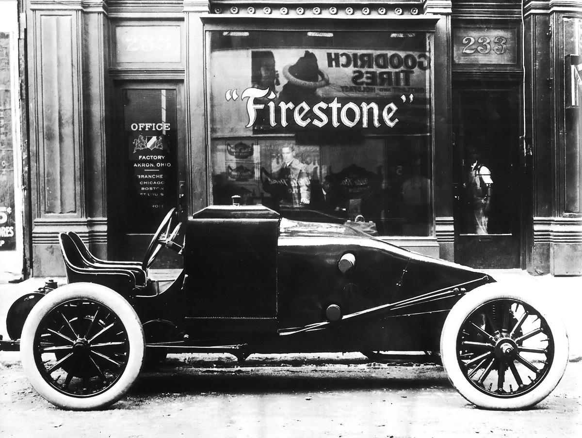
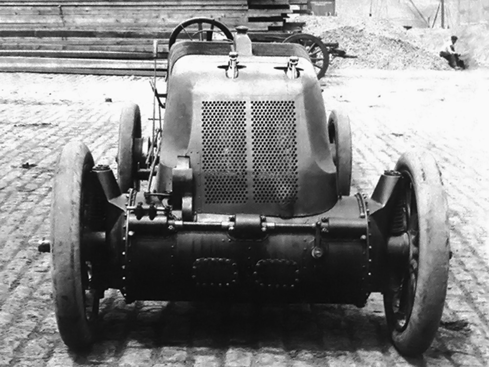
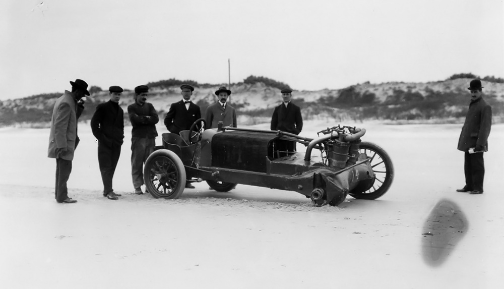
J. Walter Christie’s newly completed 1909 front-wheel drive racer in front of the Firestone office at 233 West 58th Street in New York. Note the cylindrical fuel tank at the rear of the vehicle.

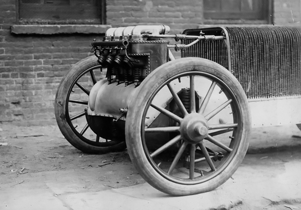
Like the previous racers, the 1909 car had its four-cylinder engine mounted transversely between the front drive wheels. The engine’s crankcase housed the transmission and formed the vehicle’s front axle. The cylindrical crankcase was 15.125 in (384 mm) in diameter and made of bronze. Behind the engine was a radiator shaped like an inverted “U” that extended from one side of the vehicle’s frame to the other. Above the vehicle’s rear axle were seats for the driver and passenger (or riding mechanic). The fuel tank was at the extreme rear of the car. The 1909 V-4 racer had a wheelbase around 102 in (2.59 m) and a track around 54 in (1.37 m).

Although the racer was powered by a V-4 like Christie’s previous two racers, the 1909 engine was an entirely new design. Extending from the crankcase toward the rear of the vehicle was a large block to which the individual cylinders were mounted. The sides of this block were integral with the vehicle’s frame. The cylinders of the 1909 V-4 engine were angled so far back that the rear row was just eight degrees from being completely horizontal. The front row of cylinders was angled 20 degrees from the rear row. The cylinders were slanted back to improve the vehicle’s weight distribution and aerodynamics.

Christie 1909 V-4 racer details

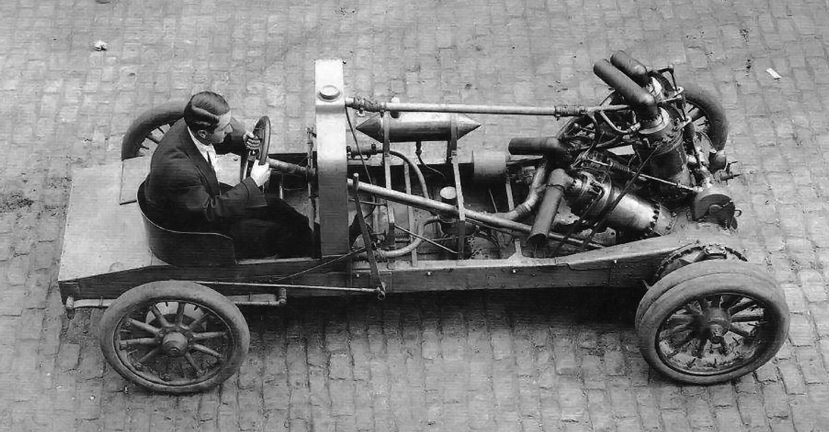
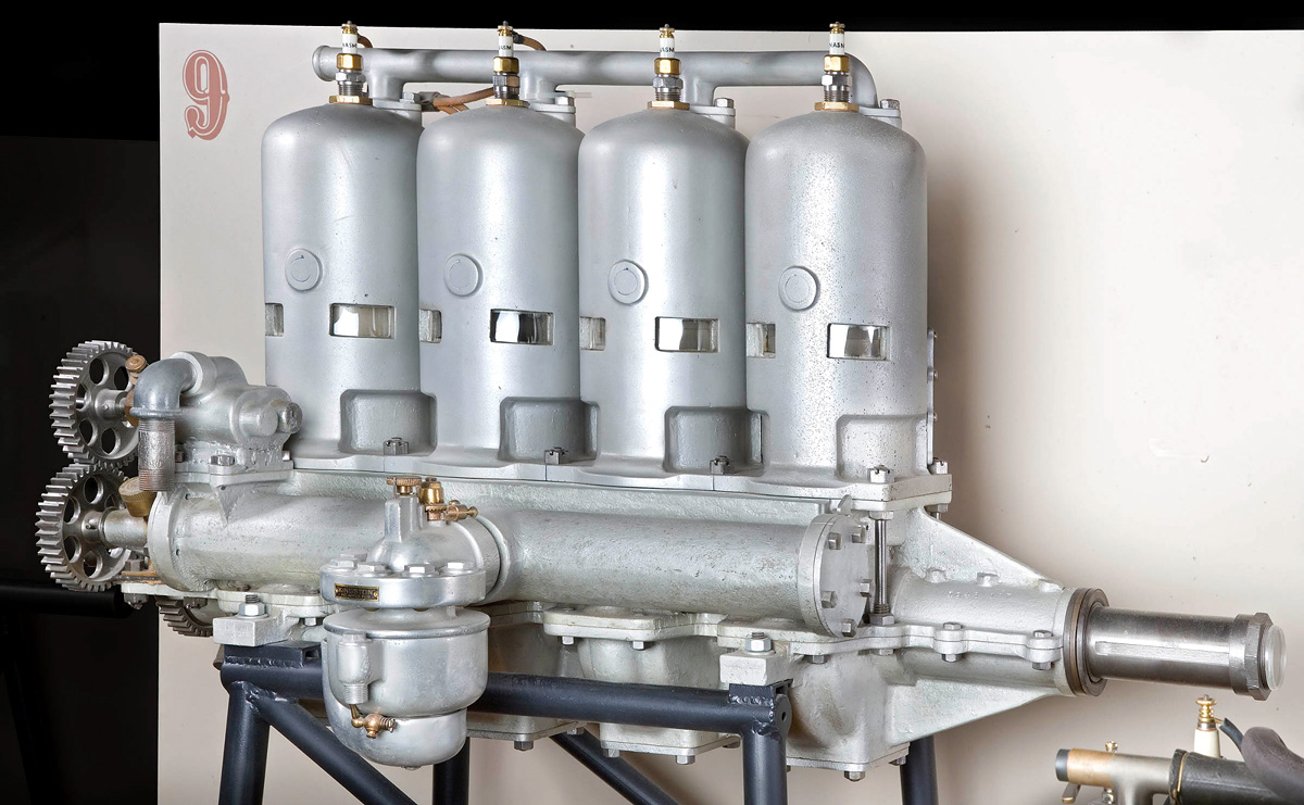
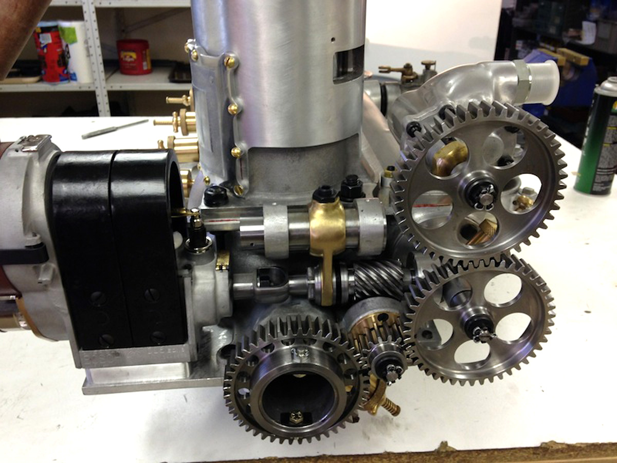
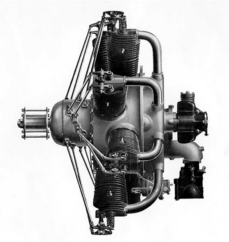
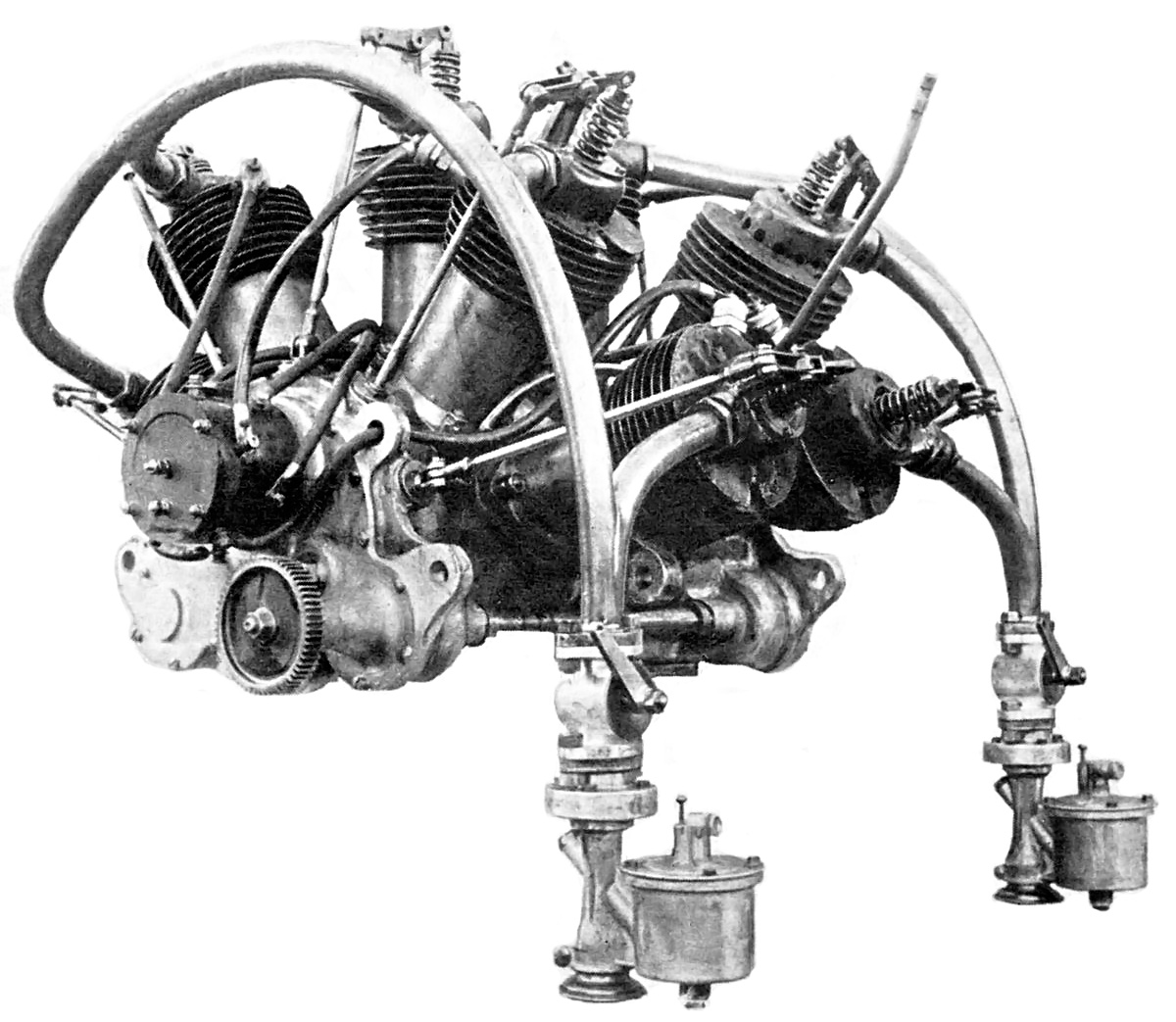
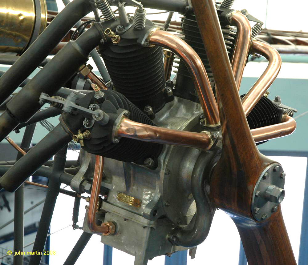
The photo on the left illustrates the 1909 Christie racer’s cross shaft (with notched drive gears at its ends) and accessory shaft. The long shaft leading back from the accessory shaft drove the camshaft. The photo on the right shows the overhead camshaft and its drive, the rocker arms, the valves, and the intake manifold. Note the large block between the crankcase and cylinders.

The forged steel crankshaft was 3.5 in (89 mm) in diameter and 19 in (483 mm) long. It had two throws and was supported by two main bearings. Attached to each crankshaft throw was one 30.5 in (775 mm) long (center-to-center) master connecting rod. The master rods served the rear row (lower) cylinders. Attached 7.0 in (178 mm) above each master rod’s big end was a 23.5 in (597 mm) long (center-to-center) articulated connecting rod. The articulated connecting rods served the front row (upper) cylinders. The incredibly long connecting rods allowed the mass of the engine to be placed toward the rear of the car in an effort to further equalize the vehicle’s weight distribution.

The engine’s cylinders had a 7.5 in (191 mm) bore and 7.0 in (178 mm) stroke, which gave the engine total displacement of 1,237 cu in (20.3 L). The engine’s output has been given as various numbers from 100 to 300 hp (75 to 224 kW), but 200 hp (149 kW) is probably close to the correct number. Each cylinder had one intake and one exhaust valve—both were 3.0 in (76 mm) in diameter and mechanically operated. The intake valves were placed on the inner side of the cylinders so that a common intake manifold could feed each row of cylinders. The upper and lower intake manifolds joined at the center of the engine, and the Christie-designed carburetor was bolted to the lower manifold.

Christie 1909 V-4 racer drive

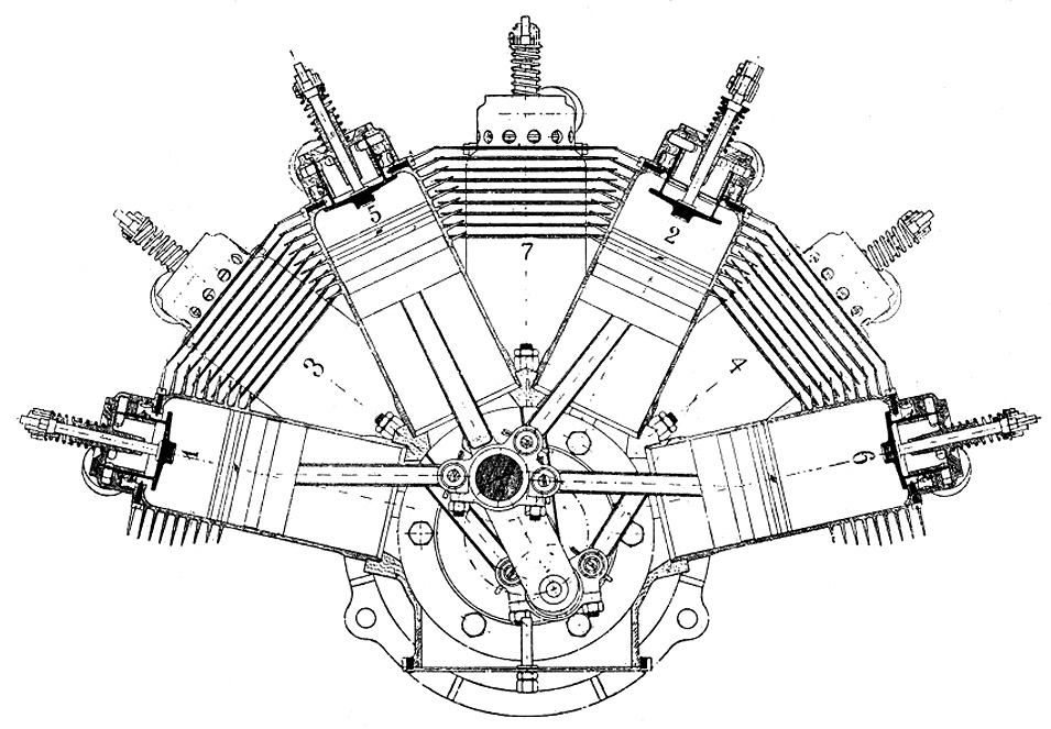
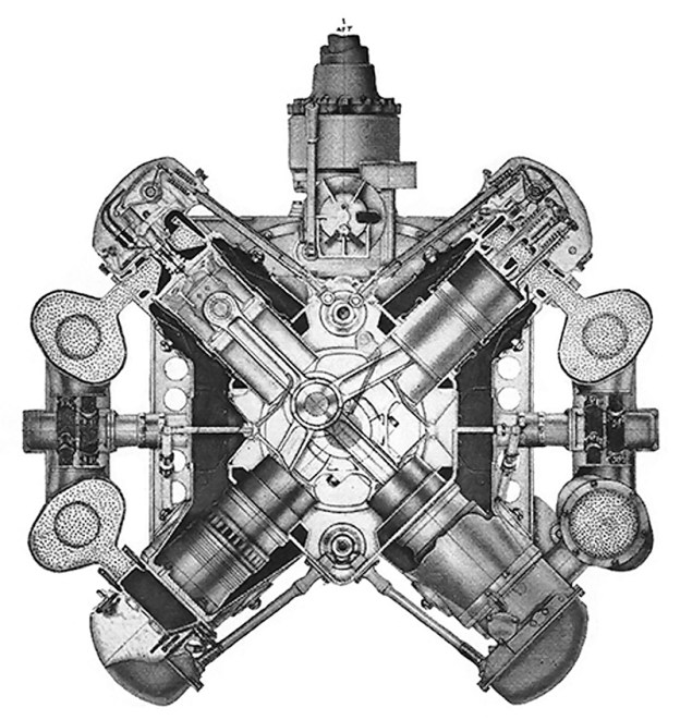
Sectional drawing of the 1909 Christie V-4 racer’s crankcase with normal, high-speed drive engaged. The short drive shaft with universal joints on its ends can be seen coupled to the engine’s crankshaft. The front cross shaft is shown with its notched gear straddling the gear of the inner universal joint.

The exhaust valves were on the outer side of the cylinders and positioned so that the exhaust gases for each cylinder vented through a small stack. The valves were actuated by separate rocker arms driven by a single overhead camshaft situated between the two cylinder rows. The camshaft was driven via beveled gears by a long shaft on the left side (from the driver’s perspective) of the engine. The long shaft was driven from the left side of an auxiliary shaft positioned above the engine’s crankcase and in front of the cylinders.

A single spark plug was installed in each cylinder and just under the intake valve. In order to achieve proper timing with the odd cylinder angles, the spark plugs for each row of cylinders were fired by separate magnetos. The magnetos were driven from the extended end of the same long shaft that drove the camshaft.

For normal, high-speed front-wheel drive operation, each end of the crankshaft was coupled via disk clutches to a short drive shaft with universal joints at each end. The short drive shaft was constructed of solid steel and was 2.25 in (57 mm) in diameter. The spindles for the drive wheels were on the outer ends of these shafts. In this configuration, the drive wheels turned once for each revolution of the engine.

Christie 1909 V-4 racer

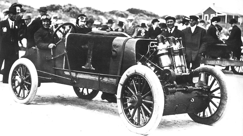
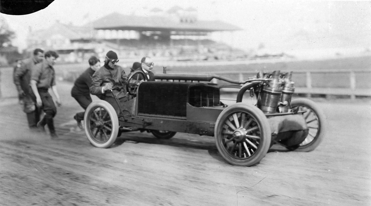
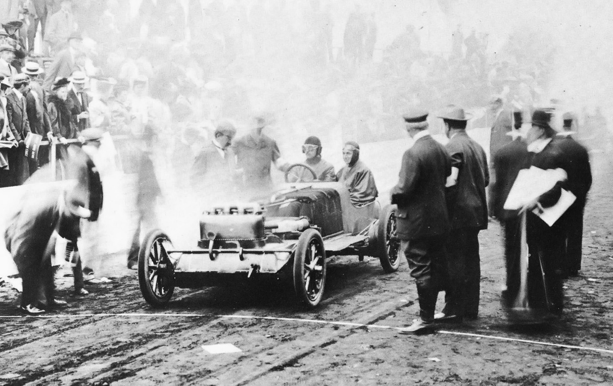
The 1909 Christie V-4 racer undergoing final checks before a run. Walter Christie is checking the water level in the radiator’s header tank. Note the thick radiator and the exhaust stacks protruding from the engine cowling.

Machined between the throws at the center of the crankshaft were 1.0 in (25 mm) wide spur teeth that drove the auxiliary shaft positioned above and slightly to the rear of the crankcase. Positioned in front of and driven by the right side of the auxiliary shaft was a cross shaft. This cross shaft could slide to decouple the drive wheels from the crankshaft and engage a reverse gear. In addition, the cross shaft could engage a low-speed gear via an intermediate gear.

Each end of the cross shaft had a notched gear that could mesh with teeth on the inner side of the short drive shaft. For normal, high-speed operation, the notch would align with the teeth on the short drive shaft, allowing for direct drive. For low-speed operation, the cross shaft would slide left, and one side of the notched gear would engage the teeth on the short drive shaft. For reverse, the cross shaft would slide right, mesh with the intermediate gear, and the other side of the notched gear would engage the teeth on the short drive shaft. Shifting levers operated various forks that slid the cross shaft and engaged or disengaged the clutches.

Christie 1909 V-4 Ormond Roberts

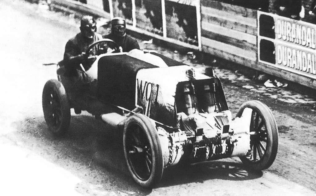
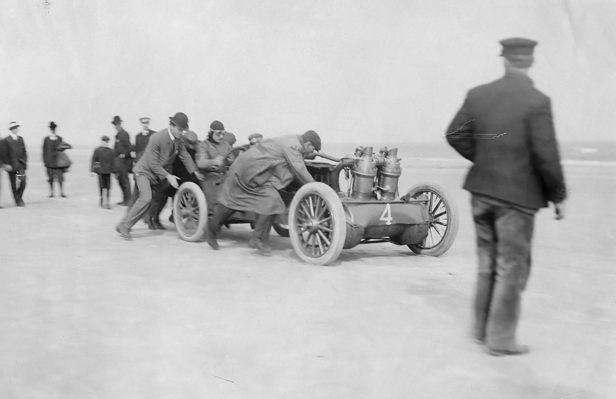
Walter Christie driving the 1909 V-4 racer on Dayton-Ormond Beach in Florida with George Robertson holding on. For the beach runs, special cowlings were installed, the passenger seat was removed, and the radiator’s header tank was altered.

The radiator was formed from 80 copper tubes in 10 sections. Five sections were positioned on each side of the vehicle, and the eight copper tubes of each section formed a half arch. The copper tubes were flattened to a width of 2.625 in (67 mm) and extended from one side of the vehicle’s frame to a header tank positioned at the upper center of the radiator. The complete radiator was 29.25 in (743 mm) high, 35 in (889 mm) wide, and 32.5 in (826 mm) long.

Three different tires sizes were intended to be used on the 1909 racer: 30 in (762 mm) tires for circle tracks, 32 in (813 mm) tires for road use, and 34 in (864 mm) tires for high speed operations. Christie estimated his racer was capable of 130 mph (209 km/h), which equates to an engine speed of 1,285 rpm with the 34 in (864 mm) tires. Christie proposed that an engine with a smaller bore of either 5.5 in (140 mm) or 6.0 in (152 mm) could be used in a touring car version of the racer. These bores would give engine displacements of 665 cu in (10.9 L) and 792 cu in (13.0 L) respectively. However, it is doubtful that engines of these sizes were ever made.

Christie 1909 V-4 racer Oldfield

Barney Oldfield in the 1909 Christie racer at one of the many race exhibitions he staged. By this time, the racer had a new radiator and a square fuel tank. The dangerous aspects of the racer were embellished by Oldfield and subsequent owners; the car was even called the “Killer Christie.” It is safe to assume that no car in the 1910s was safe at over 100 mph (160 km/h).

Christie’s new V-4 racer made its public debut on 8 July 1909 at the Blue Bonnets track in Montreal, Canada, but Christie did not find the success he had hoped for. Experiencing some engine trouble, he was able to run a 59.6 second mile (60.4 mph / 97.2 km/h) on the circle track. In the next race, Christie’s car caught fire, taking him out of the event. In early August, the car ran at Grosse Pointe, Michigan where Christie ran a 54.6 second mile (65.9 mph / 106.1 km/h)—a new record for that circle track. Christie’s speed was limited by the track’s insufficient banking, which resulted in him coasting through the turns.

For the remainder of 1909, Christie raced at several tracks but was always plagued by trouble. On the Indianapolis Motor Speedway in mid-December, Christie ran a half mile in 17.53 seconds (102.7 mph / 165.2 km/h). He was slowed again by the turns, completing a mile in 42.58 seconds (84.5 mph / 136.0 km/h). Christie’s former partner (and nephew) Lewis Strang ran a few seconds faster in his 200 hp (149 kW) FIAT.

Christie 1909 V-4 Oldfield Beachey

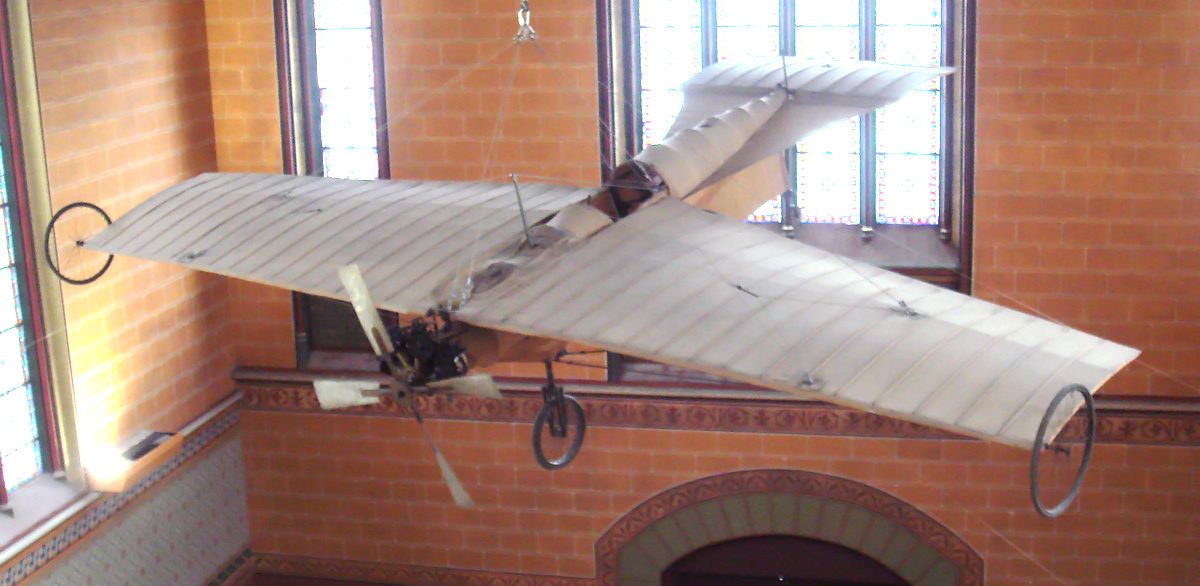
Oldfield on the Ascot track in Los Angeles, California leading Lincoln Beachey in his Curtiss Pusher in 1913.

George Robertson was hired to drive Christie’s V-4 racer at Ormond-Daytona Beach, Florida in March 1910. The car was fitted with special, aerodynamic front and rear cowlings, and the passenger seat was removed. While the racer did a respectable 32.36 second mile (111.2 mph / 179.0 km/h), it could not approach the 27.33 second mile (131.723 mph / 211.988 km/h) Barney Oldfield had previously run in the 200 hp (149 kW) Blitzen Benz. Robertson went out to make another attempt despite the Christie racer constantly overheating. In the middle of what he felt would be a record-setting run, the engine seized. Once the engine stopped, the drive wheels froze and slid along the sand. This destroyed the tires and damaged the wheels. After much work to repair the vehicle, overheating issues and carburetor problems continued to plague the racer.

Christie had grown tired of all the issues with his racer. He announced that he was done racing and exited the automobile business altogether. The V-4 racer sat until 1912 when Oldfield bought it for $750. A new radiator was installed by either Christie or Oldfield, and the original body was put back on.

Oldfield campaigned the car for four years, putting on show after show. For some of his exhibitions, Oldfield raced against aviation pioneer Lincoln Beachey in his Curtiss Pusher airplane. Oldfield did achieve some success, setting a number of records with the Christie racer. On 20 June 1915, Oldfield set a new American record when he lapped the 2 mile (3.2 km) Speedway Park track in Chicago, Illinois in 64.6 seconds (111.5 mph / 179.4 km/h). On 28 May 1916, Oldfield became the first person to exceed 100 mph (161 km/h) on the 2.5 mile (4.0 km) Indianapolis Motor Speedway track when he completed a lap in 87.7 seconds at 102.623 mph (165.156 km/h). He then upped his 2 mile (3.2 km) American record in Chicago on 5 June 1916 when he completed a lap in 63.75 seconds (112.9 mph / 181.8 km/h).

Christie 1909 V-4 racer Oldfield IMS

Oldfield and his crew by the Indianapolis Motor Speedway for their record-setting run in 1916. Leather straps are now used to secure the racer’s cowling, and what appear to be grease cups protrude from the cowl.

Damaged during the run in Chicago, Oldfield sold the car mid-June 1916. The Christie was then used in Ernest Moross’ traveling auto race shows. During World War I, the Christie racer and the rest of the show toured Canada. At some point during this time, the racer was fitted with a new cowl and body. In March 1918, the car was sold to racer Louis Disbrow and continued to be used in various shows. Some of the shows included driver Jerry Wonderlich racing against aviatrix Ruth Law in her Curtiss Pusher aircraft. Outdated and unwieldy, the last of Christie’s front-wheel drive racers was scrapped in Chicago, Illinois around April 1919. All of the bronze parts proved to be the racer’s last payout: $450.

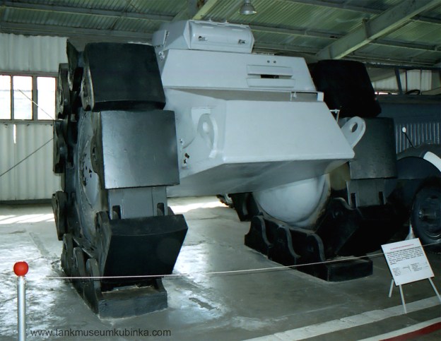
After parting with his racer in 1910, Christie had a short stint in aviation. He then built a series of front-wheel drive fire trucks. These trucks replaced the horses of existing horse-drawn units. This business venture proved quite lucrative. Christie then moved into designing tanks, which occupied his remaining days. Unfortunately, the money faded as the years went by, and Christie died nearly broke on 11 January 1944.

Christie 1909 V-4 Law Old Motor

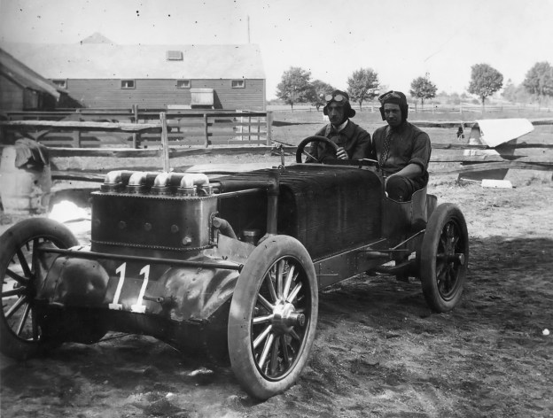
The Christie 1909 racer with its new cowl and body circa 1918. Ruth Law’s Curtiss Pusher is in the background, and her mechanic Bob Westover sits behind the wheel. Note the 300 hp claim and that the racer is still prominently labeled as a “Christie.” (Lee Stohr image via TheOldMotor.com)

Sources:
– “The Front-Wheel-Drives of John Walter Christie, Inventor” by Stan Grayson Automobile Quarterly Volume 14, Number 3 (1976)
– “Christie’s New 100-Horsepower Racer” The Automobile (5 August 1909)
– “Montreal Sees Two-Man Meet” The Motor World (15 July 1909)
– “Christie the Bright Star at Grosse Pointe” The Automobile (5 August 1909)
– “Furious Driving at Fort Erie” The Motor World (12 August 1909)
– “Under the Spell of Speed” The Motor World (26 August 1909)
– “Basle Finishes Miles Ahead” The Motor World (2 September 1909)
– “Oldfield Smashes Florida Beach Records” Automobile Topics (26 March 1910)
– “Rain Cuts Short Florida Record Breaking” Automobile Topics (2 April 1910)
– “Delay Only Increases Race Interest” Motor World (23 June 1915)
– “Oldfield Breaks Record” Motor Age (8 June 1916)
– “Barney’s Christie Junked” Motor Age (24 April 1919)
Barney Oldfield by William F. Nolan (1961/2002)
http://www.stohrdesign.com/christie-automobiles-1903-1909-a-blog (various pages)
http://theoldmotor.com/?p=114991
http://theoldmotor.com/?p=130800
http://theoldmotor.com/?p=2798

Christie 1907 V-4 Oldfield

Christie V-4 Engine 1907 Racer

By William Pearce

Shortly after John Walter Christie wrecked his V-4-powered racer practicing for the 1906 running of the Vanderbilt Cup, he went to work on his next front-wheel drive race car. He took what he learned from his first V-4 racer and from all his inline racers and applied this knowledge while building the new car. Christie planned to take his new racer to Europe as the first American vehicle to compete in the French Grand Prix. At the same time, Christie wanted to expand his Christie Direct Action Motor Car Company and start producing various automobiles of his design.

Christie 1907 V-4 build

J. Walter Christie’s 1907 V-4 racer under construction at his shop in New York. The drive shaft for the water pump can be seen behind and to the right of the front wheel and extending toward the bottom of the radiator. This shaft was driven from the bevel gear visible in front of the first row of cylinders.

While the 1907 V-4 racer closely resembled the 1906 V-4 racer, it was an entirely new design. The car’s configuration followed that of the previous Christie racers in which the engine was mounted transversely between the two front wheels. The engine’s crankcase formed the car’s front axle and housed its transmission. The car had two forward gears: a normal gear for high-speed operation and a low gear. There was also a reverse gear. Behind the engine was a large radiator in which individual copper tubes were shaped in an inverted “U” and extended from one side of the frame to the other. A header tank was at the upper center of the tubes. The driver and passenger (typically a riding mechanic) sat over the rear axle with the fuel tank behind them.

The engine’s circular crankcase was made of nickel steel and formed an integral part of the chassis. The individual steel cylinders were mounted in two staggered rows on the crankcase. The first row of cylinders leaned back about 10 degrees from vertical, and the second row was angled about 45 degrees from the first row. Each cylinder was surrounded by a copper water jacket. Cooling water exited the top of each cylinder and flowed through a common manifold to the radiator’s header tank. After flowing through the radiator, the cooled water was pulled through a circulation pump and then flowed into the lower part of the cylinder water jacket. The water pump was driven from the camshaft via a long shaft with beveled gears.

Christie 1907 V-4 engine

Detail view of the V-4 engine and how its crankcase was an integral part of the car’s frame. The cross shaft on the front of the crankcase drove low and reverse gears. Note the camshaft housing in front of the cylinders and the exhaust valve train. The camel hair lining can just be seen on the outer diameter of the flywheel housed in the crankcase. The clutch would be installed between the flywheel and the crankcase.

Each cylinder had one large, mechanically operated exhaust valve. Via a rocker arm and pushrod, all exhaust valves were actuated by a single camshaft mounted on the outside of the crankcase and in front of the first row of cylinders. From the driver’s position, the right side of the camshaft was geared to the crankshaft, and its left side was geared to the water pump drive shaft. Surrounding the exhaust valve were eight atmospheric (automatic) intake valves mounted in a manganese bronze inlet chamber. The incoming air/fuel charge flowed from the Breeze carburetor, which was positioned behind the engine, into a manifold that branched into separate intake pipes for each cylinder. This configuration gave each cylinder a different induction pipe length and led to unequal air/fuel distribution.

Many sources list the bore and stroke as 7-9/32 in (185 mm) and the total displacement as 1,214 cu in (19.9 L). However, the engine actually had a 7.25 in (184 mm) bore and stroke that gave a total displacement of 1,197 cu in (19.6 L). The 185 mm (7-9/32 in) figure probably originated from the European press rounding up the true 7.25 in (184 mm) number. Regardless, the car’s displacement was the largest of any Grand Prix racer before or since. The V-4 engine reportedly produced around 130 hp (97 kW), but it was probably closer to 100 hp (75 kW).

Christie 1907 V-4 front cowl

Christie’s V-4 racer with its full engine cowling. It seems the cowling’s grill was quickly cut away to increase airflow through the radiator. Each cylinder had short exhaust stacks, and the front cylinders expelled their exhaust through the top of the cowl.

The stagger of the cylinders allowed the use of a two-throw crankshaft. Two hollow steel connecting rods were attached to each throw. The crankshaft was supported by three main bearings. The steel pistons had concave heads and five rings; three rings were above the wrist pin, and two bronze rings were below. The underside of the piston had cooling fins to help dissipate heat. For each cylinder, a single spark plug was mounted on its Vee side near the pushrod guide. The spark plugs were fired by a battery-powered Heinz coil and communicator (distributor). The engine used splash lubrication and also a Petersen pressure feed oiler.

On each end of the crankshaft was a manganese bronze flywheel. The outer diameter of the flywheel was lined with woven camel hair to provide a friction surface. Covering the flywheel was a chrome steel cone clutch. Shafts and universal joints connected the drive wheels to the clutches and allowed for steering and independent coil spring suspension. Normal gear would lock the flywheel, clutch, and shaft together so that there was no reduction between the engine and drive wheels; for every revolution of the engine, the drive wheels turned one revolution. Normal engine speed was 1,000 to 1,200 rpm. With its 34 in (864 mm) by 4.5 in (114 mm) front tires, the car was capable of 120 mph (193 km/h) at 1,200 rpm. Of course, different size tires could be used to alter the vehicle’s acceleration and top speed. The rear tires were 34 in (864 mm) by 4 in (102 mm).

Christie 1907 V-4 French Grand Prix

Christie and Lewis Strang running in the French Grand Prix in 1907. The car was painted white for the race, the engine cowl had been cut back, exhaust valve covers had been added to the top of the cowl, engine exhaust was now piped out of the cowl and into a muffler (of sorts) seen just behind the front wheel, and crankcase breathers had been added to the front of the car. Note the oil leaking from the camshaft and cross shaft housings.

Low and reverse gears were enabled by a cross shaft on the front of the crankcase. As the cross shaft slid laterally, gears on the shaft meshed with teeth cut into the outside of the clutch drums; at the same time, the clutch disengaged from the flywheel, allowing the speed of the drive wheels to be dictated by the speed of the cross shaft. The cross shaft was geared to the crankshaft at a reduced speed.

The car was only fitted with rear brakes, but two sets were employed. One set of rear brakes acted upon the inner surface of the brake drum while the other set acted upon the drum’s outer surface. The inner and outer brakes were controlled by individual foot pedals; however, the pedals were situated so that both could be pressed simultaneously by one foot.

The rear axle was a hollow steel tube and attached to the frame by semi-elliptic leaf springs. The 25 gal (95 L) fuel tank was easily removed so that it could be inspected by the Grand Prix committee. The car used a pressed steel, channel-section frame. It had a 110 in (2.79 m) wheelbase and a 53 in (1.35 m) track (some sources say a 100 in / 2.54 m wheelbase and a 56 in / 1.42 m track). The car weighed around 1,780 lb (807 kg).

Christie 1907 V-4 GP racer

This photo was most likely taken soon after the racer returned from Europe (possibly at Morris Park, New York). The cross shaft, mufflers, and crank case breathers have been removed, but the rest of the car is still in its Grand Prix configuration—apparently still wearing white paint from the Grand Prix. Christie is in the driver’s seat. Note the oil still leaking from the front of the crankcase.

Completed in late April, the Christie racer was tested out on the streets of Long Island, New York at 4 AM. Lewis Strang, who was Christie’s ridding mechanic and nephew, accompanied Christie on this first run. Reportedly, the car broke down after about 20 mi (32 km), but the issues were not severe. The car was repaired and underwent further testing and refinement in May. The racer originally had a cowling that covered the entire engine. Due to cooling issues, the front of this cowling was removed to increase airflow through the radiator. This cowling was continually modified throughout the racer’s life.

In June, Christie, Strang, and the V-4 racer left for France. Thirty-eight cars were entered in the French Grand Prix to be run on 2 July 1907. The race consisted of 10 laps on a 77 km (47.8 mi) course laid out near Dieppe in Northern France. Christie’s racer was the lightest and one of the most powerful racers. It was allocated the race designation WC1 (for Walter Christie 1) and the 12th starting position. The Christie Direct Action Motor Car Company had arranged for several locals to assist with the racer. However, upon arriving in France, Christie and Strang discovered that the helpers were nowhere to be found. Christie and Strang spent their time repainting the car in the white and red colors required for United States racers. They then needed to register the racer in France. With all the administrative work completed, Christie and Strang did not have much time to practice and only made one test lap around the course. This session revealed a sticking exhaust valve, but there was no time for repairs.

Christie 1907 V-4 Oldfield

Barney Oldfield in the 1907 Christie V-4 racer. It is not known when or where this photo was taken, but a new engine cowling has been installed and the cross shaft has been reinstalled.

Christie and Strang started the race at 6:12 AM and had a tire failure less than two miles later; it was not a good start. Repairs were quickly made, but the car was struggling. Christie picked up the pace and ran a lap in 48 min and 49 sec (58.8 mph / 94.6 km/h). However, this was several minutes slower than the leader. Adding to the trouble of the sticking exhaust valve were a jammed clutch and an overheated main bearing. Christie and Strang retired the V-4 racer on the fifth lap.

Upon return to the United States, Christie was ridiculed for his poor showing at the Grand Prix. He responded that he had spent his own money on his effort, and, unlike other American auto manufactures, he “at least did something.” Christie went on to challenge his critics to a race “for any distance and for any amount of money, and at any time, on any road or track anywhere.” No one stepped up to accept his challenge.

Christie and Strang ran the racer at various tracks to prove its capabilities and those of the Christie Direct Action Motor Car Company. In August, Christie ran a 52.2 second mile (69.0 mph / 111.0 km/h) on the dirt track at Morris Park, New York. He then ran a 52 second lap (69.2 mph / 111.4 km/h) in Boston, Massachusetts followed by the same time at St. Paul, Minnesota. On 9 September, Christie and Strang were running at speed on the Brunots Track near Pittsburg, Pennsylvania when they struck a wrecked racer from a previous crash on the track. Christie lost control of the car, and both men were thrown from their racer. Strang was uninjured, but Christie was hospitalized with a broken wrist, a sprained back, a lacerated head, and abdominal injuries.

Christie 1907 V-4 Blakely Ormond

Ned Blakely sits behind the wheel of the Christie racer at Ormond Beach, Florida in March 1908. Although Christie made a 109 mph (175 km/h) test run, the car did not finishing any official race.

The V-4 racer was repaired, and Christie and Strang took the car to Birmingham, Alabama. Christie was still recovering from his injuries and did not drive much. The next stop was New Orleans, Louisiana, but the meet was delayed. Christie made arrangements to send the car back to New York and returned there himself. However, the car never arrived. Subsequently, Christie discovered that Strang had taken the car back to Birmingham, Alabama were he set a record on 16 October, lapping the mile track in 51.6 seconds (69.8 mph / 112.3 km/h). Strang also ran the V-4 racer at a few other events.

This unauthorized use of his car deeply upset Christie, and it was the end of his association with Strang. Some of Strang’s behavior can be attributed to the negative influence of his and Christie’s manager, William Pickens. To make matters worse, before Christie knew the car was missing, he had sold it to William Gould Brokaw. The arrangement allowed Christie to continue to drive the 1907 V-4 racer so long as he kept it in good repair. When Christie finally tracked down the missing racer and had it returned to his shop in New York, the engine had a cracked cylinder and other damage.

Christie 1907 V-4 late

An undated photo illustrating the many changes made to the 1907 V-4 racer. The cross shaft on the front of the crankcase and the engine cowling have been completely removed. A more conventional radiator has been installed along with new exhaust stacks. A much smaller fuel tank (just in front of the radiator) has replaced the original tank. Note the twin front tires on the right drive wheel. Race promoter Ernest Moross is behind the wheel.

Repairs (which included a new crankcase) were made, and Ned Blakely was tasked with racing the car at Ormond Beach, Florida in March 1908. Unfortunately, in a 100 mi (161 km) race on the first day of the event, a valve broke and took the car out of the race. Repairs were completed, but during a 256 mile (412 km) race on the third day, a spark plug broke off and damaged a cylinder, ending the racer’s participation at the event. Sometime during this event, Christie covered a mile in 33 seconds (109.1 mph / 175.5 km/h) on a test run, but it was not officially timed.

The car was again repaired. In early June, Morton J. Seymour was behind the wheel of the racer practicing for an event on Long Island, New York when he crashed and most likely overturned the car. The radiator was destroyed, but Christie managed to repair the car enough to run without cooling water for an attempt on the 1 km (.62 mi) record. Seymour covered the km in 26.6 seconds (84.1 mph / 135.3 km/h)—not fast enough for a new record.

Christie 1907 V-4 late track

Another view of the modified 1907 racer. The car still has the twin right drive wheels. Christie is in the driver’s seat. Note how the steering column passes through the radiator.

The racer was repaired yet again and further modified. A new (more conventional) radiator was installed. A small fuel tank was installed in front of the radiator, and the large, rear tank was removed. The low and reverse gears and the engine cowling were completely removed. Seymour and Christie went on to drive the car at a few events. After this, Christie and his good friend Barney Oldfield toured the country and made many appearances at various tracks.

At some point, after the new radiator, the V-4 racer had twin front right wheels installed to help the front-wheel drive vehicle on the circle tracks. It is not clear how often the car ran in this configuration. In December 1908, the racer was running at Tanforan Park near San Francisco, California, but a cracked cylinder took it and its driver Hughie Hughes out of competition. In January 1909, Hughes crashed the car at a race in Phoenix, Arizona, and that was the last known event for Christie’s 1907 V-4 racer; the car’s final disposition is not known. By this time, the Christie Direct Action Motor Car Company had fallen into receivership. Undaunted, Christie had established the Walter Christie Automobile Company in September 1908 and went to work on another V-4 racer.

Note: Some sources state that Blakely ran a 35 second mile in the 1907 V-4 racer at “a beach near Atlantic City” prior to March 1908. However, I was unable to find specifics to this event and feel it may have been confused with the 35.2 second run Christie made at Ventnor Beach, which is near Atlantic City, in 1905.

Christie 1907 V-4 DePalma Clark

A photo from the 1908 Minnesota State Fair with Christie, DePalma, and Clark. The fair was held in St. Paul from 31 August to 5 September. Note that the Christie racer has only one front right drive wheel.

Sources:
– “The Front-Wheel-Drives of John Walter Christie, Inventor” by Stan Grayson Automobile Quarterly Volume 14, Number 3 (1976)
– “America’s Candidate for the Grand Prix” by W. F. Bradley The Automobile (11 April 1907)
– “Grand Prix Failures 6. The 1907 Grand Prix Christie” The Bulletin of the Vintage Sports-Car Club No. 281 (Autumn 2013)
– “Christie Racer for the Grand Prix” The Automobile (21 February 1907)
– “The Grand Prix” The Automobile (11 April 1907)
– “Christie Racer is Being Tried Out” The Automobile (2 May 1907)
– “Florida’s Meet Supplied More Records than Races” by John C. Wetmore The Automobile (12 March 1908)
– “Christie’s New 100-Horsepower Racer” The Automobile (5 August 1909)
http://www.stohrdesign.com/christie-automobiles-1903-1909-a-blog (various pages)
http://blog.hemmings.com/index.php/2010/05/31/how-strang-met-his-death/
http://www.findagrave.com/cgi-bin/fg.cgi?page=gr&GRid=112329874
http://hclib.tumblr.com/post/9466387511/auto-racing-at-the-minnesota-state-fair-1908

Christie 1906 V-4 Strang Vanderbilt

Christie V-4 Engine 1906 Racer

By William Pearce

In the early 1900s, John Walter Christie built a series of front-wheel drive automobiles; each had its inline, four-cylinder engine mounted transversely between the front wheels. The engine’s crankcase also served as the vehicle’s axle. With only so much room between the wheels, the bore of the engine’s cylinders was limited, and Christie found that other cars were producing more power and outperforming his. In late 1905, Christie devised a way to increase the capacity and power of his engines by using a V-4 configuration.

Christie 1906 V-4 wheel Ormond Beach

J. Walter Christie’s 1906 racer after hitting debris on Ormond Beach, Florida in January 1906. Note the exhaust manifolds on the front of the engine, the original cylinder water jackets, and the lack of a radiator header tank. The induction pipe can be seen behind the engine.

After the Vanderbilt Cup race in October 1905, Christie took his 1905 racer, with the 828 cu in (13.6 L), 70 hp (52 kW) inline engine, and modified it with a new V-4 engine. Essentially, the axle of the 1905 racer was reworked to accommodate four individual cylinders. The car maintained its normal (high-speed) gear and low forward and reverse gears. The drive wheels were coupled to the crankshaft, and wheel slip was limited in the normal gear. For low gear and reverse gear, a five to one reduction was employed, and the drive wheels were allowed to slip relative to one another. The individual cylinders were arranged in two rows and were staggered to keep the engine compact. The cylinders were mounted to the top of the axle, and the angle between the rows was around 22.5 degrees.

The carburetor was placed low and behind the engine. The air/fuel mixture traveled from the carburetor and through a large pipe to the top center of the engine. Attached to the end of the pipe was an intake manifold with four outlets to provide the incoming air charge to each cylinder. The air/fuel mixture flowed into each cylinder though a single intake port that led to a chamber ringed around the outer cylinder head. In this ring were eight 1.5 in (38 mm) atmospheric (automatic) intake valves. A single spark plug was positioned below the inlet valve chamber ring.

Christie 1906 V-4 push Ventnor Beach

Christie behind the wheel of his racer at Ventnor Beach, New Jersey in April 1906 . The car had been modified with short exhaust stacks, redesigned cylinder water jackets, and a header tank above the radiator. It was here that Christie set a four-cylinder automobile speed record by covering a mile in 35.2 seconds (102.3 mph / 164.6 km/h).

At the center of the induction ring but separate from it was a single 3.125 in (79 mm) mechanically operated exhaust valve. The exhaust valve was controlled by a rocker arm actuated by a pushrod. The pushrods were driven from a camshaft situated behind the second row of cylinders. Originally, the exhaust valve was enclosed in a housing that had an exhaust port on its side. Each cylinder had its own exhaust manifold attached to the port; this configuration was replaced by a short exhaust stack that extended from the top of the cylinder.

The steel cylinders were originally surrounded by electrolytic (oxygen-free) formed copper water jackets. However, these jackets were prone to leaking and were replaced by jackets made of sheet metal. Water from the radiator entered the water jacket of each cylinder near its bottom. The water flowed out the top of each cylinder and into a common manifold that delivered it back to the radiator/header tank. The radiator was the same originally used with the inline engine in which copper tubes 5/16 in (8 mm) in diameter and 64 in (1.63 m) long were bent into an inverted “U” shape, extending from one side of the vehicle to the other. A header tank was later added above the middle of the radiator. Later still, the header tank was integrated into the middle of the radiator.

Christie 1906 V-4 push Empire

Lewis Strang push starting Christie in the 1906 V-4 racer at the Empire City Race Track in May 1906. On this track, Christie tied the then-current mile-track record of Barney Oldfield at 53 seconds (67.9 mph / 109.3 km/h). The racer is shown with an eight section radiator.

Sources disagree on the engine’s size, the engine’s power, and the car’s weight. Some sources list the engine as having a 7.375 in (187 mm) bore and stroke and a total displacement of 1,260 cu in (20.7 L). Other sources give a 7.5 in (191 mm) bore, a 7.0 in (178 mm) stroke, and 1,237 cu in (20.3 L) total displacement. The engine’s output varies by source between 100 to 135 hp (75 to 97 kW), but 100 hp (75 kW) is probably close to the correct figure. The car’s reported weight varies between 1,800 and 2,150 lb (816 to 975 kg). The crankshaft was 2.75 in (70 mm) in diameter and made of chrome steal. It was most likely a two-throw crankshaft supported by three main bearings. This would mean two connecting rods were attached side-by-side to one crankpin. The engine is said to have weighed 470 lb (213 kg).

Christie’s V-4 racer made its debut at Ormond Beach (north of Daytona Beach), Florida in January 1906. The car was numbered 14 for this event and experienced several issues. The right front wheel broke off after the racer struck some debris on the beach during a practice run. The car was repaired, but the copper water jackets leaked, and the car had engine cooling issues. Christie had to stop and refill the radiator with four miles left in the 30 mile race. Christie went on to finish the race in 37 minutes and 24.6 seconds, averaging 48.1 mph (77.4 km/h).

The car’s next appearance was in April at Ventnor Beach, near Atlantic City, New Jersey. The racer was now numbered 4 and was modified with new cylinder water jackets, open exhaust stacks, and the header tank above the radiator. Christie covered a mile in 35.2 seconds at 102.3 mph (164.6 km/h), making the racer the fastest four-cylinder automobile in the world. In May, Christie lapped the mile track at Empire City (Yonkers, New York) in 53 seconds (67.9 mph / 109.3 km/h). This speed tied the mile-track record held by Barney Oldfield.

Christie 1906 V-4 Strang Vanderbilt

Christie (at the wheel) and Strang ready for the Vanderbilt Cup race. Note the new header tank and the ten section radiator. Also visible are the springs on the pushrods that held the exhaust valves closed.

By September 1906, Christie had readied his V-4 racer for the Vanderbilt Cup. The car now had the integrated header tank installed, and the radiator had ten sections rather than the eight sections used earlier. George Robertson was to drive the car for the Vanderbilt Cup, but he crashed it during a qualifying run on September 15. The damage was not too severe, and Christie made the repairs that night. However, Christie did not notice that the steering arm had been cracked in the accident.

On the morning of 16 September, Christie and his riding mechanic (and nephew) Lewis Strang took the car out for a test run. As the car quickly gained speed, the steering arm failed and Christie lost control of the racer. The car smashed into a telegraph pole and was too damaged to be repaired. Fortunately, Christie and Strang were not injured. The pair went on to race in the 1906 Vanderbilt Cup in a converted touring car that the Christie Direct Action Motor Car Company had built. After the race, Christie went to work on his next racer; he had already set his sights on putting his front-wheel drive cars on the international stage.

Christie 1906 V-4 crash Vanderbilt

The destroyed Christie 1906 V-4 racer after the steering arm broke on 16 September. Note how the steering wheel was broken in the accident. Fortunately, Christie and Strang were not injured.

Sources:
– “The Front-Wheel-Drives of John Walter Christie, Inventor” by Stan Grayson Automobile Quarterly Volume 14, Number 3 (1976)
– “The Reconstructed Christie racer and Its Record at the Automobile Carnival” Scientific American (9 June 1906)
– “Record-Holding Racers at the Ormond Automobile Meet” Scientific American (10 February 1906)
– “Now for the Selection of the American Cup Team” The Motor Way (20 September 1906)
– “Christie’s New 100-Horsepower Racer” The Automobile (5 August 1909)
http://www.stohrdesign.com/christie-automobiles-1903-1909-a-blog (various pages)
http://www.vanderbiltcupraces.com (various pages)

Christie 1905 racer and Robertson

Christie Inline Engine Race Cars

By William Pearce

John Walter Christie was born in New Milford, New Jersey on 6 May 1865. From 1881 to 1900 (age 16 to 25), he worked in and was a consultant for various engineering firms. During this time, he designed a new style of gun turret for Navy ships. This design proved lucrative, and in 1900, Christie opened his own machine shop, Walter Christie Machinery, in New York City, New York. He opened the Christie Iron Works the very next year in 1901. As the dawn of the automotive age shone on the United States, the successful Christie was able to own an automobile, but the engineer in him could not help but see ways to improve its design.

Christie 1903 Auto side

J. Walter Christie in his 1903 front-wheel drive auto, the first built in the United States. Just visible behind the rear wheel is the radiator. Christie took this car to Ormond Beach, Florida in January 1904.

By late 1903, Christie had built his own automobile, and it was unlike any other. He designed not only the car but also its engine and transmission. Christie felt that an automobile drive system should pull the vehicle (like a train or carriage), not push it (like a boat). As a result, Christie focused on a front-wheel drive system in which the engine was situated transversely between the front wheels. He believed this arrangement would create a light, simple, high-speed auto. Christie’s first vehicle design closely followed a patent that he took out in 1904. Christie’s front-wheel drive car was the first of its kind built in the United States.

The front axle of Christie’s auto was also the engine’s crankcase and housed its transmission. The cylinder block was mounted atop the axle housing. The auto had a low gear and a reverse gear; both provided a five to one reduction and enabled the drive wheels to slip relative to one another. For normal (high-speed) operation, the drive wheels were coupled to the crankshaft and wheel slip was limited. Each drive wheel had a clutch to facilitate the gear change. In addition, each drive wheel had two universal joints, and shafts that allowed for steering and independent coil spring suspension. The rear axle used leaf spring suspension.

Christie 1904 patent drive

A drawing from Christie’s 1904 patent illustrating the front-wheel drive system’s drive shafts, universal joints, and coil spring suspension. Note the offset X-beams of the connecting rods.

The 1903 car originally accommodated a driver and passenger (or mechanic, which for Christie was often his nephew Lewis Strang), but it was later fitted with a second row of seats for three passengers. The car only had rear brakes, and they were operated by a hand lever or a foot pedal. The auto weighted about 1,400 lb (635 kg). The engine for the 1903 car is believed to have had a 5.0 in (127 mm) bore and a 6.0 in (152 mm) stroke. It displaced 471 cu in (7.7 L) and produced around 30 hp (22 kW). The connecting rods were of the X-beam type. The X-beam was offset relative to the crankpin to allow for a shorter crankshaft and to provide clearance for the crankshaft’s three main bearings. A handle for crank-starting the engine protruded from the front of the axle, but the car was typically push started.

The engine had an intake over exhaust (F-head) valve arrangement. A set of four intake valves with a small combustion chamber space beneath them was positioned adjacent to the cylinder. The intake valves were atmospheric (or automatic): they were held closed by a weak spring and pulled open by the vacuum created during the piston’s downward stroke. A single, large exhaust valve was situated under the intake valves. The exhaust valves were mechanically operated. They were actuated by pushrods driven by a camshaft geared to the engine’s crankshaft. Each cylinder had a single spark plug positioned in the combustion chamber space between the exhaust valve and intake valves. The spark plugs were fired by a communicator (distributor) driven from an auxiliary shaft.

Christie 1903 Auto front

The 606 cu in (9.9 L), 30 hp (22 kW) engine of the 1903 Christie car. The spark plugs are in the center of the combustion chamber space adjacent to the cylinders. A set of four intake valves are above each spark plug, with a single exhaust valve below. Note the exhaust manifold. The hand crank on the front of the car was used to start the engine.

For induction, the air/fuel mixture flowed from a remote carburetor and through a long intake pipe to the engine. The intake manifold sat atop the engine and was split into four runners. Each runner connected to one group of four intake valves

The engine’s cylinders were covered by water jackets formed from sheet copper and screwed to the cylinder block. A remote water pump drew cooling water from the radiator and sent it to the engine. After flowing through the engine, the cooling water was taken from the top of the engine and sent to the radiator. The radiator was positioned under the rear of the car for better weight distribution. The water pump was driven from the same shaft that drove the ignition system’s communicator.

Christie 1904 racer

Christie’s 1904 racer with its unusual radiator and eight-intake-valves-per-cylinder engine. Christie sits in the driver’s seat.

Christie took the 1903 car to Ormond Beach, Florida (just north of Daytona Beach) in January 1904. In his car, Christie averaged 63.1 mph (101.5 km/h) in a 10 mile (16 km) race and completed a 25 mile (40 km) endurance race. However, the engine did experience some issues from lack of lubrication. Christie continued to campaign this car at a few events, but he also built a larger car more dedicated to racing in 1904.

Christie’s 1904 racer used an engine of similar configuration to the 1903 engine. However, each cylinder had two sets of intake valves, for a total of eight per cylinder. The new set of four intake valves was positioned directly above the piston. Each of the four intake runners that sat atop the engine had two outlets, one for each set of four valves. The engine’s bore and stroke were 6.25 in (159 mm) and 6.75 in (171 mm) respectively. The engine had a total displacement of 828 cu in (13.6 L) and produced 70 hp (52 kW). Its crankshaft and pistons were made of carbon steel, and its crankcase and flywheels were made of a manganese bronze alloy. The spark plugs were fired from a battery powered coil ignition.

Christie 1904 racer engine

A close up of the engine in the 1904 Christie racer. Note the springs for the mechanical exhaust valves, the lack of an exhaust manifold, and the outlet for the sheet copper water jacket.

In the 1904 car, the driver and passenger were moved to the extreme rear of the vehicle for better weight distribution. In addition, the fuel tank was situated under the seat. A new radiator was installed in the middle of the auto. It consisted of around 60 long, copper tubes shaped in an inverted “U” extending from one side of the car to the other. The radiator was positioned so that air passed over it rather than through it; this configuration limited its effectiveness. No information regarding where or if the 1904 car was raced has been found. Some believe that it was a modification of the 1903 car, but it was not; the engine, axle, and frame were all different.

Christie continued to develop his concept of the front-wheel drive racer and built another car toward the end of 1904. The car, sometimes referred to as the Blue Flyer, made its debut at Ormond Beach in January 1905. It was very similar to the 1904 racer but had a new frame and axle. The car was powered by the same 70 hp, 36-valve (four being exhaust), four-cylinder engine used in the 1904 car. However, its orientation had been changed so that the exhaust valves were toward the rear of the vehicle.

Christie 1905 racer engine

The engine of the 1905 Christie racer was the same used in the 1904 racer; it was repositioned so that the exhaust valves faced toward the rear of the vehicle. The protuberance on the front of the engine was the water jacket outlet used on the 1904 car. The two sets of four valves for one cylinder are visible in the right image.

A new radiator was developed consisting of 12 sections (although photos seem to indicate only eight sections). Each of the sections was made up of eight copper tubes that were 5/16 in (8 mm) in diameter and 64 in (1.63 m) long. Attached to each section were 340 aluminum fins that were 5 in (127 mm) long and 1 in (25 mm) wide. Reportedly, this gave the radiator a surface area of some 20,000 sq in (12.9 sq m), but as with the earlier radiator, air flowed over its surface. Cooling water was taken from the water jacket between the cylinders and delivered to an expansion tank in front of the radiator. The water then flowed through the radiator and into the bottom of the water jacket on both sides of the engine. The 1905 racer had a 96 in (2.44 m) wheel base, a 57.5 in (1.46 m) track, and weighed 1,800 lb (816 kg).

For each revolution of its 40 in (1 m) wheels, the car travel 10 feet (3 m) forward. Given the car’s direct drive, 90 mph (145 km/h) would be achieved at 792 rpm. Christie raced the car on Ormond Beach in January 1905 and covered a mile in 42.2 seconds (85.3 mph / 137.3 km/h). Christie went on to win a 50 mile (80 km) race and received the Lozier Trophy. However, his was the only car to finish the race. Regardless, people were impressed by Christie and his automobiles. Based on the interest in his vehicles, Christie formed the Christie Direct Action Motor Car Company in March 1905 to manufacture passenger and race cars.

Christie 1905 twin engine racer

This image shows Christie’s 1905 racer modified with a second engine. The rear engine appears to be identical to the engine used in the 1903 car. The radiator appears to have eight sections.

In search of more power, Christie installed a second engine in the 1905 car. The car was lengthened, and the second engine was installed behind the driver and passenger. The second engine produced around 30 hp and powered the rear wheels. The engine appears to be the same four intake and one exhaust valve engine used in the 1903 car (and used in the 1906 car described below). The two engines provided a total of around 100 hp (75 kW). The twin-engined car made its debut on 4 July at Morris Park, New York. The car proved to be a handful but went on to run at Cape May, New Jersey in July, where it covered a mile in 37.0 seconds (97.3 mph / 156.6 km/h). In August, Christie ran a km in 25 seconds (89.5 mph / 144.0 km/h). In September, that flying km time was lowered to 23.25 seconds (96.2 mph / 154.8 km/h), for which Christie won the Cape May Trophy. Later in September, the rear engine was removed from the racer after it failed while Christie was attempting a new mile record. (It appears two additional radiator sections were added at this time, bringing the total to 10.)

Christie then set his sights on the Vanderbilt Cup race scheduled for 14 October in Long Island, New York. George Robertson was selected to drive the car in the race, but he was not familiar with the peculiarities of the car and its front-wheel drive. Robertson had trouble during qualifications on 23 September and ultimately crashed the car. The needed repairs took too long, and Christie’s car was out. However, the Cup Commission made a bizarre decision that is still not understood. Three qualified cars were removed from the race, and three cars that did not qualify were reinstated; Christie’s racer was one of the three reinstated cars.

Christie 1905 racer and Robertson

Christie and George Robertson sit in the 1905 racer ready for a Vanderbilt Cup practice run . The rear engine has been removed, and the radiator now has 10 sections. Robertson crashed the car a short time later.

Christie worked feverishly, almost up to the start of the race, to completely repair his racer, which had suffered some engine damage. Christie drove his car in the race due to Robertson’s inexperience with the unique racer. At the start, Christie’s 1905 racer ran poorly and completed the first lap at only 29.2 mph (47.0 km/h). The engine then smoothed out, and the second lap passed at 56.0 mph (90.1 km/h). On the fourth lap, Italian driver, and race leader, Vincenso Lancia left the pits right as Christie was speeding by. Christie tried unsuccessfully to avoid a collision. Both drivers and their mechanics escaped with only minor injuries. Christie’s car was damaged beyond repair, and the time needed to repair Lancia’s car effectively took him out of contention.

Christie rebuilt the 1905 racer with a new V-4 engine. The car made its debut in January 1906. Unfortunately, it crashed on 16 September during qualification for the 1906 running of the Vanderbilt Cup. Christie quickly took stock of his resources to find a new car for the races held on 6 October.

Christie 1906 touring car

The Christie Direct Action Motor Car Company’s 1906 touring car. This car was stripped of its body and modified to race in the 1906 Vanderbilt Cup. Note the stripe painted on the axle.

The Christie Direct Action Motor Car Company had just completed a seven-passenger touring car. With no other car available, it was the only option for the race. Christie quickly returned to his New York shop and removed the touring car’s blue painted body and black leather seats. A new body was fabricated with the seats over the rear axle. The steering was redone and the steering shaft extended. Other efforts were made to lighten the 2,300 lb (1,043 kg) touring car.

The touring car’s radiator was removed and a new one installed. The new radiator was similar to those used in the previous Christie cars but had a header tank at its center. The engine of the touring car was very similar to the original Christie F-head engine from 1903 and to the engine used in the rear of the 1905 car—all had four atmospheric intake valves and one mechanical exhaust valve. It is possible that these three engines were actually the same engine. However, the bore and stroke of the touring car’s engine was increased from the 1903 engine by .375 in (10 mm) and 1.0 in (25 mm) respectively. The touring car’s engine had a 5.375 in (137 mm) bore and a 7.0 in (178 mm) stroke. The engine produced 50 hp (37 kW) at 1,200 rpm from its 635 cu in (10.4 L). The car had a 102 in (2.59 m) wheel base and a 56 in (1.42 m) track. In race trim, the touring car’s weight was dropped to 1,895 lb (860 kg) race-ready.

Christie 1906 Vanderbilt start

Christie and his nephew Lewis Strang sit in the race-ready touring car stripped for the 1906 Vanderbilt Cup race. This image was taken at the start of an elimination trial. The stripe on the axle noted in the previous image is just visible.

At less than half the power of most of the other cars in the Vanderbilt Cup, Christie did not stand much of a chance. After running for a while in seventh place, Christie had slipped back to 13th place out of the 18 competitors, averaging 44.7 mph (71.9 km/h) when the race was called. Even so, Christie had shown that his front-wheel drive cars were as reliable and competitive as those of other manufacturers that used a conventional powertrain. After the race, Christie refocused on his V-4 racers.

Christie’s 1906 touring-car-turned-racer was eventually sold to William Gould Brokaw. The car reappeared in March 1908 at Ormond Beach, Florida and was driven by R. G. Kelsey. The racer failed to finish a 125 mile (201 km) race but placed second and averaged 62.4 mph (100.4 km/h) in a 256 mile (412 km) race held two days later. Also, Kelsey covered a mile in 42.8 seconds (84.1 mph / 135.3 km/h). The further activities and ultimate disposition of the racer is unknown.

Christie 1906 Vanderbilt

Christie and Strang taking a turn during the 1906 Vanderbilt Cup race. Although the bore had been increased, the engine could very well be the same as the original 1903 engine.

Sources:
– “The Front-Wheel-Drives of John Walter Christie, Inventor” by Stan Grayson Automobile Quarterly Volume 14, Number 3 (1976)
– “Motor-Vehicle” US patent 761,657 by Walter Christie (granted 7 June 1904) 2.7 MB pdf
– “A New American Automobile” Scientific American (28 January 1905)
– “The First Christie Front Drive Touring Car” The Automobile (13 September 1906)
– “Now for the Selection of the American Cup Team” The Motor Way (20 September 1906)
– “Christie’s New 100-Horsepower Racer” The Automobile (5 August 1909)
– “Florida’s Meet Supplied More Records than Races” by John C. Wetmore The Automobile (12 March 1908)
http://www.stohrdesign.com/christie-automobiles-1903-1909-a-blog (various pages)
http://www.vanderbiltcupraces.com (various pages)

Roberts 6-X engine side

Roberts Motor Company Aircraft Engines

By William Pearce

In the early 1900s, the Roberts Motor Company of Sandusky, Ohio made a series of two-stroke engines for boats. With aviation gaining popularity, it was only natural for the company to adapt its engines for aircraft use. Roberts aircraft engines first appeared in 1911 and were designed by the company’s founder and president Edmund W. Roberts.

Roberts 4-X engine Smithsonian

A four-cylinder Roberts 4-X engine on display at the Smithsonian National Air and Space Museum in Washington, DC. Note the tubular housing to which the carburetor is attached. Inside the housing is the tubular distributor sleeve for delivering the air/fuel mixture to the cylinders. The water pump is mounted on the upper rear of the housing. (National Air and Space Museum image)

Roberts Motor Company’s aircraft engines differed from their marine counterparts in that they were engineered to be as light as possible. To keep parts (and associated points of failure) to a minimum, the Roberts two-stroke engines did not use poppet valves. In addition, Roberts’ engines incorporated unique designs to overcome drawbacks generally found with two-stroke engines, namely the air/fuel mixture pre-igniting as it entered the cylinder, causing a backfire.

The engines’ cast cylinder liners were constructed of a proprietary alloy called “Aerolite,” which Roberts said was as light as aluminum but twice as strong and had the wear properties of cast iron. The individual cylinder liners were covered by an aluminum water jacket. A ring around the base of the cylinder liner would fit into a recess around the bottom of the water jacket, securing the two together. The cylinder liner’s spark plug boss (and that of the decompressor if present) passed through the water jacket casting. The outer diameter of the boss was threaded, and a nut secured the top of the water jacket and cylinder liner. This nut would also draw up the base of the liner into the water jacket, securing the whole cylinder assembly.

Roberts 6-X engine side

The six-cylinder Roberts 6-X engine. The crankcase casting provided a space under each cylinder for the air/fuel mixture. Each space was sealed by crankshaft main bearings. Note the two exhaust ports for each cylinder.

The pistons were made of cast iron and were attached to drop forged I-beam connecting rods made of vanadium steel. The connecting rods were attached to the crankshaft by a bronze strap about a third the size of the crankpin. (Firing every revolution, the pistons of a two-stroke engine are not pulled down by the crankshaft and therefore do not need a full-size connecting rod bearing cap.) The crankshaft was hollow and made of drop forged steel. The cylinders were secured to the crankcase by four bolts, with adjacent cylinders sharing their bolts. The crankcase was made from Magnalium, an aluminum and magnesium alloy that made it lighter and stronger than an aluminum crankcase of the same thickness.

The carburetors were mounted to a tubular housing that ran along the right side of the engine. Inside of this housing was a tubular distributor sleeve (also called a rotary induction valve) driven by an intermediate gear that engaged the accessory drive gear mounted on the end of the crankshaft. The distributor sleeve rotated at crankshaft speed and had ports to control the air/fuel mixture flow from the carburetor into the crankcase. The crankcase was constructed so that a small space existed under each cylinder for the incoming charge. The carburetor aligned with multiple ports in the distributor sleeve to allow a constant flow into the distributor, but each cylinder matched up with a single port to control air/fuel delivery. For each cylinder, the incoming charge passed from the distributor though a port in the side of the crankcase. The distributor helped eliminate the risk of backfires and distributed the air/fuel mixture equally to all the cylinders, allowing the engine to run smoothly.

Roberts 4-X Rotary Distributor

The tubular distributor sleeve of a Roberts 4-X engine. The ports at the center of the tube aligned with the carburetor.

The distributor port opened as the piston moved up and drew in the air/fuel mixture. The port then closed as the piston moved down on its power stroke, compressing the incoming charge underneath. Two ports in the piston aligned with ports in the cylinder wall when the piston was near bottom dead center. This alignment allowed the pressurized, incoming air/fuel mixture to flow from the crankcase into a space on the outer side of the cylinder. In this space, Roberts installed what they called a “cellular by-pass” to prevent backfires. The incoming charge flowed through the cellular by-pass and then through another set of ports positioned above the piston. The piston’s top had a large deflector to send the incoming air charge toward the top of the combustion chamber to improve exhaust gas scavenging. This deflector was positioned on the intake port side of the piston. Two exhaust ports were located on the opposite side of the cylinder from the intake ports and were also controlled by the piston so that all ports were uncovered when the piston was near bottom center.

The cellular by-pass was a series of flat and corrugated plates creating a honeycomb mesh. The large surface area of the cellular by-pass extinguished any flame should a backfire occur, but it did not decrease the engine’s efficiency in normal operation. The Roberts engine’s resistance to backfiring allowed a leaner mixture to be used, thus increasing the engine’s fuel economy. The cellular by-pass also helped mix and vaporize the fuel in the incoming charge.

Roberts 6-X parts Weeks

Various parts for one of the two Roberts 6-X replica engines built for Kermit Weeks. Note the deflector on the top of the pistons and the two ports in the side of the pistons. A decompressor valve can be seen on the top of the cylinder in the lower left corner. (Fantasy of Flight image)

The water pump was mounted at the right rear of the engine and was driven from the gear driving the tubular distributor sleeve. The pump drew water from the radiator and then pushed it through a passageway on the right side of the crankcase. Each cylinder had an open port that aligned with a coolant passageway in the crankcase. The water flowed into a small channel in the cylinder and then around the exhaust ports and up into the cylinder’s water jacket. It then flowed out the top of the cylinder and into a manifold that led back to the radiator. The engine was lubricated by the oil and fuel mixing and via splash lubrication. Grease cups were used to lubricate the main bearings.

A single spark plug was mounted in the center of each cylinder’s semi-hemispherical combustion chamber. The spark plug was fired by a Bosch magneto mounted at the rear of the engine. The magneto was driven by a helical gear via the intermediate gear that meshed with the accessory drive gear on the end of the crankshaft. An advance fork mounted above the magneto shaft moved the helical gear of the magneto along its shaft to either advance or delay ignition—an adjustment that could be made by the pilot while in flight.

Roberts 6-X gears Weeks

The exposed accessory gears of the Robert 6-X replica. The crankshaft drove an intermediate gear, the backside of which engaged the magneto drive shaft. To advance or delay the timing, the helical gear for the magneto drive shaft could be adjusted by the brass advance fork above it. The intermediate gear drove the gear for the tubular distribution sleeve, which in turn drove the gear for the water pump. (Fantasy of Flight image)

The Roberts four-cylinder engine was known as the 4-X. It had a 4.5 in (114 mm) bore, a 5 in (127 mm) stroke, and a total displacement of 318 cu in (5.2 L). The engine produced 50 hp (37 kW) at 1,200 rpm. It used one carburetor, and its magneto turned at twice crankshaft speed. Its crankshaft was 2.5 in (64 mm) in diameter, with crankpins 1.75 in (44 mm) in diameter and 2.5 in (64 mm) long. The crankshaft was supported by five main bearings; the one toward the propeller was 6.375 in (162 mm) long. The crankshaft was 40 in (1,016 mm) long and weighed 17.5 lb (7.9 kg). The 4-X was 40.5 in (1.03 m) long, 25 in (.64 m) tall, 24 in (.61 m) wide, and weighed 170 lb (77 kg).

The six-cylinder engine was known as the 6-X. Like the 4-X, it had a 4.5 in (114 mm) bore and a 5 in (127 mm) stroke. The engine’s total displacement was 477 cu in (7.8 L), and it produced 75 hp (56 kW) at 1,200 rpm. The 6-X used two carburetors, and its magneto turned at three times crankshaft speed. Its crankshaft and crankpins were the same size as the 4-X’s. The crankshaft was supported by seven main bearings, was 52 in (1,321 mm) long, and weighed 27.5 lb (12.5 kg). The 6-X was 52.5 in (1.33 m) long, 25 in (.64 m) tall, 24 in (.60 m) wide, and weighed 240 lb (109 kg).

Roberts 6-XX engine

The Roberts 6-XX engine with exhaust manifolds and enclosed accessory gears.

A further development of the six-cylinder engine was the 6-XX. This engine had its accessory gears covered and bathed in oil. Its bore and stroke were enlarged to 5.5 in (140 mm) and 6 in (152 mm) respectively. The 6-XX’s total displacement was 588 cu in (14.0 L), and it produced 125 hp (93 kW) at 1,100 rpm. The engine used two carburetors. Its Bosch HL magneto turned at 1.5 times crankshaft speed to fire one of the two spark plugs in each cylinder. The other spark plug was fired by a Delco distributor. The 6-XX’s crankshaft was 3 in (76 mm) in diameter, with crankpins 2.5 in (64 mm) in diameter and 3.5 in (99 mm) long. The crankshaft was supported by seven main bearings; the one toward the propeller was 12 in (305 mm) long. The 6-XX was approximately 60.5 in (1.54 m) long, 27.5 in (.70 m) tall, 24 in (.60 m) wide, and weighed 390 lb (177 kg).

The Roberts engines were refined over time and used by a good number of early aviation pioneers. By 1913, all Roberts engines had the exposed accessory gears enclosed like those on the 6-XX engine. This change necessitated the magneto be repositioned. The cylinder liners were now made of cast iron, and the water jackets were made of Aerolite. The pistons were also made of Aerolite, which reduced their weight by over 2 lb (.9 kg) each. The tubular distributor sleeve was mounted on four sets of ball bearings to reduce friction. Dual ignition, like that used on the 6-XX, was available as an option on the 6-X engine. A starting crank attached to the end of the crankshaft was also an option.

Roberts 6-X 1913 rear

The rear of the 1913 Roberts 6-X engine showing the enclosed accessory gears, repositioned magneto, and optional hand starting crank on the end of the engine. The decompressors can be seen on the top of the cylinders. These were used to make starting the engine easier.

As two-stroke Roberts engines were surpassed by new four-stroke engines, like the Curtiss OX-5 and Hispano-Suiza 8, the company struggled to keep up. By 1918, the 6-X engine had its bore and stroke increased to 5 in (127 mm) and 5.5 in (140 mm) respectively, giving a total displacement of 648 cu in (10.6 L). The tubular distributor was replaced by more conventional intake manifolds, and the engine produced 100 hp (75 kW) at 1,200 rpm. The 6-X now weighed 368 lb (167 kg).

There is also some indication that a V-12 was planned and possibly constructed by Roberts in the late 1910s. This engine was known as the E-12. It had a 6 in (152 mm) bore, a 6.5 in (165 mm) stroke, and a total displacement of 2,205 cu in (36 L). The engine produced 350 hp (261 kW) at 1,200 rpm. Each cylinder had its own crankpin, and 13 main bearings supported the crankshaft. The E-12 weighed 990 lb (490 kg).

Roberts 6-X Weeks

One of Weeks’ Roberts 6-X replica engines. The engines were built to power a replica Benoist XIV flying boat. The Benoist is a pusher, which is why the outlet for the coolant pipe is toward the propeller shaft. Note the brass grease cups for lubricating the crankshaft main bearings. The cover on each cylinder is for the cellular by-pass. (Fantasy of Flight image)

The Roberts Motor Company left the aviation field by 1919 to focus on marine engines. Around this time, the company changed its name to Roberts Motors. A few years later, Roberts Motors went out of business. A number of early Roberts four- and six-cylinder aircraft engines still exist in museums.

Recently, Kermit Weeks of Fantasy of Flight in Polk City, Florida commissioned the creation of two replica Roberts 6-X engines. One of the engines was a test engine, and the other would be installed in a Benosit XIV flying boat replica. An original engine was reverse engineered, allowing these engines to be built. Below is a video from 2013 of Mr. Weeks checking on the progress of the Roberts 6-X engine construction at Vintage & Auto Rebuilds in Chardon, Ohio. Both Roberts 6-X replica engines have since been completed and test run.


Sources:
Roberts Aviation Motors by The Roberts Motor Co. (1912)
– “Construction of Cylinder of Internal Combustion Engines” US patent 1,210,537 by Edmund W. Roberts (granted 2 January 1917)
The 1913 Model 6-X by The Roberts Motor Co. (1913)
Fantasy of Flight Blog (various entries relating to the Roberts engine and Benoist flying boat replica)
Aerosphere 1939 by Glenn Angle (1940)
(Jane’s) All the World’s Aircraft 1918 by C. G. Grey (1918)

Hawker Fury Sabre LA610

Hawker Fury I (Sabre-Powered) Fighter

By William Pearce

While testing of the Tempest prototypes was still underway in 1942, the Hawker design team began to study ways to improve and lighten the fighter aircraft. Some of their ideas were influenced by the study of a German Focke-Wulf Fw 190 A-3 that had inadvertently landed in Britain in June 1942. The Fw 190 proved smaller and lighter that its Hawker-built contemporaries. In September 1942, the British Air Ministry issued Specification F.6/42 calling for a new fighter aircraft. Hawker proposed three versions of its improved Tempest, each to be powered by a different engine: the V-12 Rolls-Royce Griffon, the 18-cylinder Bristol Centaurus radial, and the H-24 Napier Sabre.

Hawker Fury Sabre LA610

The Napier Sabre-powered Hawker Fury LA610 in-flight exhibiting exactly what a high-performance aircraft should look like.

The Air Ministry supported Hawker’s designs under Specification F.2/43 issued in February 1943. In April 1943, Specification N.7/43 was issued for a new Navy fighter. Sydney Camm, Hawker’s chief designer, felt that arresting gear and folding wings could be added to the “improved Tempest” design to make it meet the requirements laid out in N.7/43. This plan was approved, and Specification N.22/43 was issued to Hawker for the new Navy fighter. Around this time, the two new Hawker aircraft received their official names: Fury (for the Royal Air Force’s land-based version) and Sea Fury (for the Fleet Air Arm’s naval version).

From the beginning, the preferred power plants were the Napier Sabre for the Fury and the Bristol Centaurs for the Sea Fury. Although the detailed design drawings for the Sabre-powered Fury were finished first, developmental delays of the new Sabre VII (NS.93/SM) engine resulted in the Centaurus- and Griffon-powered Furys being completed first. The Centaurus-powered Fury (NX798) first flew on 1 September 1944 followed by the Griffon-powered Fury (LA610) on 27 November 1944.

Hawker Fury Griffon LA610

The Hawker Fury LA610 originally flew with a Griffon engine and contra-rotating propellers. The large duct under the spinner housed the radiator, similar to that used on the Tempest V and VI.

Although the Air Ministry ordered 200 Sabre-powered Fury I aircraft in August 1944, there were rumors that Sabre production would be shut down following the war’s end. In October 1944, the Ministry of Aircraft Production (MAP) assured Hawker that Sabre production would continue. In November 1944, the MAP requested a Sabre-powered Fury prototype be built utilizing the Griffon-powered LA610 airframe. However, in February 1945 the Fury I order was reduced by 50 aircraft to 150. But in March 1945, two additional Sabre-powered prototypes (VP207 and VP213) were requested. Work to install a Sabre engine in LA610 began in July 1945. With the war over and the future of fighting aircraft pointing toward jet power, orders for the Fury I were reduced again in September 1945 to 120 units.

In December 1945, the Air Ministry had informed Hawker that ground attack would be the Fury I’s primary role. Hawker felt the aircraft was not suited for this because of its liquid-cooled engine, and it did not have the armor needed for a ground attacker. As a result, in February 1946, the number of Furys on order was further reduced to 60—and even those were in jeopardy. During this time, modifications of the LA610 airframe had been completed, but the Sabre VII engine was not ready. Rather than wait for the engine, a Sabre VA (2,600 hp / 1,939 kW) was substituted. Soon, a Sabre VII was installed, and Fury LA610 was flown for the first time with its intended power plant on 3 April 1946.

Hawker Tempest I HM599 flight

The Hawker Tempest I (HM599), with its close-fitting cowl and wing radiators, was a stepping stone to the Fury I.

While the rest of the aircraft remained the same as the other prototypes, the power section of LA610 was completely different. A streamlined cowling was installed to cover the liquid-cooled Sabre engine. Coolant radiators were installed in the inboard wing sections, replacing additional fuel tanks. Cooling air would enter the wing’s leading edge, pass through the radiators, and exit via shutters under the wing. This configuration was similar to that used on the sole Tempest I prototype (HM599)—production did not occur because the Air Ministry perceived the wing radiators as too vulnerable to combat damage. The radiator shutters of the Fury I were automatically controlled based on engine temperature. A split duct under the spinner supplied intake air to the engine via the duct’s upper section. Air from the lower duct was directed through engine oil coolers and then out the bottom of the cowling.

Not only was it one of the most beautiful aircraft ever built, the Sabre-powered Fury proved to be the highest performance piston-engine aircraft built by Hawker. The 24-cylinder Napier Sabre engine was a horizontal H layout with two crankshafts. The engine had a 5.0 in (127 mm) bore, 4.75 in (121 mm) stroke, and displaced 2,238 cu in (36.7 L). The Sabre VII utilized water/methanol injection to boost power and was capable of 3,055 hp (2,278 kW) at 3,850 rpm with 17 psi (1.17 bar) of boost. To transfer this power to thrust, the Fury I used a 13 ft 3 in (4.0 m) four-blade Rotol propeller. A five-blade propeller like the Sea Fury’s 12 ft 9 in (3.9 m) Rotol unit was considered, but the decreased weight of the four-blade unit proved decisive in its adoption.

Hawker-Fury-Sabre-LA610-rear

This rear view of the LA610 Fury shows how well the 3,055 hp (2,278 kW) Sabre-engine was fitted to the airframe, enabling the aircraft to exceed 480 mph (775 km/h). Note the large 13 ft 3 in (4.0 m) four-blade propeller.

The Sabre-powered Fury had a top speed of 483 mph (777 km/h) at 18,500 ft (5,639 m) and 422 mph (679 km/h) at sea level. In contrast, the 2,560 hp (1,909 kw) Centaurus-powered Sea Fury had a top speed 460 mph (740 km/h) at 18,000 ft (5,487 m) and 380 mph (612 km/h) at sea level. The Sabre Fury’s initial rate of climb was 5,480 ft/min (27.8 m/s), and it could reach 20,000 ft (6,096 m) in 4.1 minutes. By comparison, The Sea Fury’s initial rate of climb was 4,320 ft/min (21.9 m/s), and it took 5.7 minutes to reach 20,000 ft (6,096 m). The Fury I’s service ceiling was 41,500 ft (12,649 m). All Fury and Sea Fury aircraft had the same 38 ft 5 in (11.7 m) wingspan. At 34 ft 8 in (10.6 m), the Sabre-powered Fury was 1 in (25.4 mm) longer than the Sea Fury. The Fury I had an empty weight of 9,350 lb (4,241 kg) and a loaded weight of 12,120 lb (5,498 kg).

On 14 August 1946, the remaining Fury I aircraft on order were cancelled. Of the three Fury I prototypes, LA610 would remain with Hawker for testing, VP207 would be completed and loaned to Napier for engine testing, and VP213 would be used for parts and not completed. VP207 was chosen to go to Napier because it had a larger radiator that could handle developmental power increases of the Sabre VII engine. With the cancellation of the Fury I there was no longer a need for the Sabre VII engine, and its development was stopped; Napier would not take over VP207. VP207 was completed by Hawker and first flew on 9 May 1947. Hawker retained the aircraft as a company demonstrator for a period of time. The final disposition of LA610 has not been definitively found, but it is believed that the aircraft was scrapped in the late 1940s. VP207 was stored and maintained in Hawker’s facility at Langley Airfield until the mid-1950s, when the aircraft was scrapped.

Hawker Fury Sabre LA610 taxi

Fury LA610 preparing for a flight. The air scoop under the spinner, and the wing radiators can clearly be seen in this image.

Although the Fury never progressed beyond the prototype phase, the Sea Fury did enter production, with some 789 aircraft built (number varies by source)—including prototypes and 61 two-seat T.20 trainers. Sea Furys served in Korea, were the last front-line piston-engine aircraft operated by the Royal Navy Fleet Air Arm, and were sold to and used by various other countries. A number still fly today, but due to the rarity of the Bristol Centaurus engine, many have been re-engined with Wright R-3350s. In addition, two Sea Furys have been built up for racing with Pratt & Whitney R-4360 engines, and one has a Pratt & Whitney R-2800. But none have looked quite as stunning or performed as well (in military trim) as the Napier Sabre-powered Hawker Fury I.

Hawker Fury Sabre VP207

The Sabre-powered Hawker Fury VP207 at the Society of British Aircraft Constructors show at Radlett in September 1947. Some believe the aircraft was painted silver with a red stripe, but the stripe was actually blue. (Robert Archer image via Victor Archer / American Motorsports Coverage)

Sources:
Sea Fury in British, Australian, Canadian & Dutch Service by Tony Buttler (2008)
British Secret Projects Fighters & Bombers 1935-1950 by Tony Buttler (2004)
Jane’s All the World’s Aircraft 1947 by Leonard Bridgman (1947)
Hawker Sea Fury (Warbird Tech Volume 37) by Kev Darling (2002)
RAF Fighters Part 2 by William Green and Gordon Swanborough (1979)
War Planes of the Second World War: Fighters Volume Two by William Green (1961)
Tempest: Hawker’s Outstanding Piston-Engined Fighter by Tony Buttler (2011)
Hawker Typhoon, Tempest and Sea Fury by Kev Darling (2003)
Aircraft Engines of the World 1947 by Paul H. Wilkinson (1947)

Marchetti MP Cam Action

Marchetti Cam-Action Engines

By William Pearce

Paul J. Marchetti was born in Italy in 1889. In his adolescence, he became interested in machines, engineering, and aircraft. In 1910, when he was 21 years old, Marchetti emigrated from Lucca, Italy to the United States in search of greater opportunities. He worked his way west and supported himself as a logger, all the while dreaming of entering the aviation business.

Marchetti MP Cam Action side

The Marchetti eight-cylinder, cam-action aircraft engine of 1927. Note the stagger of the front and rear cylinders.

Unfortunately, there is little information about Marchetti, his life, and his inventions. By 1922, he was working with Henry A. Nordwick in Stockton, California. Nordwick was working on designing a radial engine in which the crank throw was replaced by a cam with four lobes. A roller on the big end of the connecting rod made contact with the cam, its points creating the piston strokes. Another Nordwick and Marchetti engine design dating from 1923 had the big end of each connecting rod attached to its own crank, which was geared to a main central gear.

By 1924, Marchetti was in San Francisco, California and filed a patent of his own for a broad-arrow engine using either a three- or four-lobe cam in place of the crankshaft. Still working with Nordwick, another patent was filed for an eight-cylinder radial with a two-lobe cam. A lever extended from the big end of each connecting rod and was attached to the crankcase. Also connected to this lever was an auxiliary piston. Fed by pressurized air, the auxiliary piston forced the connecting rod to be in contact with the cam at all times. One auxiliary piston was positioned between each main piston.

Nordwick Marchetti cam engine patents

Drawings from Nordwick and Marchetti cam engine patents. The patent for the four-lobe cam design (left) was filed in 1922, and the patent for the eight-cylinder engine with auxiliary pistons (right) was filed in 1924.

Nordwick and Marchetti focused on inline engines in 1925. They designed a two-lobe cam engine, again using a lever extending from the big end of the connecting rod to the crankcase. That same year, Marchetti patented an inline engine under his business name: Marchetti Motor Patents. For this engine, the crankshaft throws were replaced with disks, offset to the crankshaft’s centerline. A connecting rod ran in a grove in each disk, and the disk’s offset would create the up and down strokes for the piston. The circular disk could also be substituted in favor of a lobed design for increased engine performance.

In 1926, Marchetti took out a patent on an inline engine with a two-lobe cam driving the pistons. The connecting rods were paired together via a rocker so that when one piston was at top dead center the other piston would be at bottom dead center. This configuration was also suggested for a U engine with two separate cam (crank) shafts.

Marchetti Motor Patents

Drawings from the Marchetti cam engine patents. The 1924 broad-arrow engine design is on the left, and the 1925 inline cam disk design is on the right.

1927 saw Marchetti focus on the business side of his dreams. His company, Marchetti Motor Patents, Inc., was officially formed with $2,000,000 of capital and operated out of the newly completed Russ Building, the tallest building in San Francisco until 1964. Marchetti worked on new engines and aircraft. In 1928, ground was broken for the Marchetti Motor Patents factory at Mills Field (now San Francisco International Airport). The factory had an expected output of 100 aircraft and 1,000 engines per year.

With his business established, Marchetti designed and built a new cam engine. While incorporating some aspects of the previous engine designs, this engine also had some unique features that are not found in any of the patents filed by Marchetti. However, the connecting rod arrangement and cam were similar to those found in a patent filed solely by Nordwick in 1926.

Marchetti MP info

Marchetti Motor Patents Inc. advertisement from 1929.

The new engine was an air-cooled, eight-cylinder radial. The cylinders were slightly staggered, making two rows of four cylinders. Twin two-lobe cams replaced the conventional crankshaft. Via roller bearings, the front cam actuated the connecting rods for the front cylinders, and the rear cam actuated the connecting rods for the rear cylinders. One fore and one aft cylinder were paired together by a common bell crank attached to the big end of the connecting rods. The center of this bell crank was the pivot point and was attached to the crankcase. The cams were staggered so that when one of the paired cylinders was at top dead center, the other cylinder was at bottom dead center. Since each cam had two lobes, there would be four piston strokes (or one power stroke) for each revolution. Marchetti referred to this design as a “cam-action” engine.

Each of the engine’s cylinders had one intake and one exhaust valve at the center of its head. The valves were actuated by pushrods driven at the front of the engine. Two spark plugs were located just below the valves of each cylinder and were fired by a magneto driven from the rear of the engine. A carburetor attached to the lower rear of the engine fed the air/fuel charge into a blower (weak supercharger). The blower helped mix the air/fuel charge, which was then distributed to the cylinder via separate manifolds. The engine had a 4.0 in (102 mm) bore, a 4.25 in (108 mm) stroke, and a total displacement of 427 cu in (7.0 L). Initially, 135 hp (101 kW) was expected from the engine, but 160 hp (119 kW) was achieved after testing. The engine weighed 350 lb (159 kg).

Marchetti MP Cam Action

Cutaway view of the Marchetti cam-action engine. The rear cam can barely be seen in the rear of the crankcase. Note how each cam actuates one “row” of cylinders. The bell crank for the upper right cylinder pair can be seen clearly. The bell crank attached to the connecting rods and pivoted in the middle, where it was mounted to the crankcase.

The eight-cylinder engine was first run in 1927. Most sources say only one engine was built, but some claim more were built. The engine passed a 400 hour maximum load test, and 2,200 hours were accumulated with no apparent signs of wear. Marchetti modified a Cessna AW for flight testing the eight-cylinder radial, but it is not known if the engine was ever installed. This aircraft was designated Marchetti M-I

Marchetti MP M-II Arrow advert

Advertisement from September 1929 for the Marchetti M-II Arrow and its four-cylinder engine cam-action engine.

Another Marchetti aircraft was the M-II Arrow—a two-place monoplane to be powered by a Marchetti inline, four-cylinder, air-cooled, cam-action engine of 100 hp (75 kW). The M-II was constructed of wood covered by fabric. On the drawing board was the Marchetti M-III—an eight passenger, all metal aircraft intended for passenger service. It was to be powered by two Marchetti eight-cylinder cam-action radials.

With his aircraft and aircraft engine manufacturing plans underway, Marchetti continued to chase his dream of becoming a pilot. On 31 August 1929, one week before the plant opened, Marchetti took off from Mills Field to look over his nearly finished factory and log some of the two hours remaining before he could get his pilot’s license. He flew into a fog bank, and what happened next is not known. A short time later, Marchetti’s aircraft was seen falling from under the fog bank in an inverted flat spin. The aircraft crashed half a mile (.8 km) from shore into San Francisco Bay. Rescue boats reached the scene as fast as possible, but it was too late. Marchetti’s body was found in the submerged fuselage.

The Marchetti M-II Arrow was completed and flown, but it is not known which engine powered it. While it is possible that it flew with a Marchetti inline cam engine, it is more likely that another four-cylinder engine was installed. Marchetti’s grand aviation plans drifted into oblivion after his death. Marchetti Engine Patents Inc. was sold to William Rider and then resold to United Aircraft Sales where it faded to obscurity. What happened to the M-I, M-II Arrow, or any of the cam-action test engines is not known. It is believed that the M-III transport never progressed beyond the design phase.

Marchetti MP M-II Arrow

The complete Marchetti M-II Arrow with its unidentified engine. The aircraft carried the registration X-98M. (Frank Rezich image via www.aerofiles.com)

Sources:
– “Falls to Death: Paul Marchetti” Oakland Tribune (1 September 1929)
– “Marchetti Motor to Revolutionize Airplane Industry” Ukiah Dispatch Democrat (12 May 1928)
– “The Business of Building Aircraft” San Francisco Business (11 September 1929)
– “Internal Combustion Engine” US patent 1,374,164 by H. A. Nordwick (granted 5 April 1921)
– “Internal Combustion Engine” US patent 1,528,164 by H. A. Nordwick (granted 3 March 1925)
– “Internal Combustion Motor” US patent 1,538,208 by H. A. Nordwick et al (19 May 1925)
– “Engine” US patent 1,654,378 by P. Marchetti (granted 27 December 1927)
– “Internal Combustion Engine” US patent 1,597,474 by H. A. Nordwick et al (granted 24 August 1926)
– “Internal Combustion Engine” US patent 1,624,277 by H. A. Nordwick et al (granted 12 April 1927)
– “Internal Combustion Motor” US patent 1,667,213 by P. Marchetti (granted 24 April 1928)
– “Motor” US patent 1,624,269 by P. Marchetti (granted 12 April 1927)
– “Duplex Cam Motor” US patent 1,630,273 by H. A. Nordwick (granted 31 May 1927)
Aerosphere 1939 by Glenn Angle (1940)
http://www.aerofiles.com/_ma.html

REP 7-cylinder

R.E.P. Fan (Semi-Radial) Aircraft Engines

By William Pearce

Robert Esnault-Pelterie was born in France on 8 November 1881. In the early 1900s, he began experimenting with a glider modeled after the Wright Brothers’ glider of 1902. Esnault-Pelterie had experienced trouble with the Wrights’ wing warping technique and switched to ailerons in 1903. In 1906, Esnault-Pelterie began constructing a powered aircraft of his own design as well as an engine to power it. Esnault-Pelterie named the aircraft the R.E.P. 1 and it first flew in 1907. A new feature of the aircraft was a control stick, which Esnault-Pelterie patented. That patent made Esnault-Pelterie a rich man once royalties were paid after World War I. While the unique engine that he designed was the first in a family of engines known as R.E.P., their success would not endure like that of the control stick.

REP 7-cylinder

Front view of the R.E.P. seven-cylinder fan engine. Exhaust gases flowed out the holes around the top of the cylinders. The intake manifold can barely be seen behind the cylinders. In this view, the four cylinders on the right shared an intake manifold as did the three cylinder on the left.

Esnault-Pelterie’s first engine was an air-cooled, seven-cylinder fan engine. Sometimes referred to as a semi-radial, this engine had cylinders that were fanned-out on the top of the crankcase and not positioned around its entirety like a true radial. The cylinders were arranged in two rows—the front had four cylinders, and the rear had three cylinders. This configuration solved lower cylinder lubrication issues of radial engines, and air-cooling issues of inline engines.

The cast iron cylinders were attached to an aluminum crankcase. The upper part of the cylinder had cooling fins to dissipate heat. At the very top of the cylinder was a large, single valve. The valve was shaped like a piston and inverted, with the valve stem attached to underside of the head. When the valve was completely closed, a flange on its head would seat against the cylinder head and seal the cylinder. When the valve was partially open, exhaust gases flowed around the flange and escaped through ports in the cylinder head. When the valve was completely open, ports in its sides aligned with ports in the cylinder head to allow the intake mixture to flow into the cylinder.

REP 7-cylinder section

In this section view of the R.E.P. seven-cylinder engine, the cylinders are numbered by firing order. Cylinder 5 has the intake/exhaust valve completely closed. Cylinder 1 shows the valve partially open to allow exhaust gases to exit the cylinder. Cylinder 2 shows the valve completely open to allow the air/fuel mixture into the cylinder. Note the master/articulated connecting rod arrangement.

The valve was actuated by a rocker arm attached to the cylinder. The rocker arm was moved via a pushrod that was operated by a cam ring inside the engine. Each row of cylinders had its own cam ring positioned at the rear of the engine, and the cam rings had stepped lifts. The first step opened the valve part way to allow the exhaust gases to vacate the cylinder. The second, higher lift completely opened the valve to allow the fresh air/fuel mixture into the cylinder. For the intake, the cylinders were separated into left and right groups, with the left group (when viewing the engine from the rear) having an additional cylinder. Each group shared a common intake manifold with a carburetor attached to its end. The intake manifold was attached to the upper rear of the cylinder. Exhaust gases flowed out though ten holes around the cylinder’s top; there were no exhaust stacks.

A single spark plug was installed in the side of the cylinder and fired by an ignition coil powered by a battery. The pistons were made of steel and had two oil rings. They were attached to the connecting rods by trunnions bolted to the underside of the piston. The connecting rod for each row of cylinders had one master rod, and the rest were articulating rods. The crankshaft had two throws offset 180 degrees and was supported by two main bearings. To balance the crankshaft, Esnault-Pelterie left the crankpin solid for the row with an additional cylinder, and the crankpin for the row with one fewer cylinder was drilled hollow.

REP 10-cylinder side

This side view of the R.E.P. 10-cylinder engine illustrates how it was comprised of two five-cylinder engines bolted front-to-front. Note the rocker arm arrangement and the single valve. The pictured engine was equipped with magnetos.

The engine had a 3.35 in (85 mm) bore and 3.74 in (95 mm) stroke. The seven cylinders displaced a total of 230 cu in (3.8 L). The engine produced 30 hp (22 kW) at 1,500 rpm and weighed 150 lb (68 kg). A five-cylinder version was also built with three cylinders in the first row and two in the second. It produced 20 hp (15 kW) at 1,500 rpm from its 164 cu in (2.7 L) and weighed 118 lb (54 kg). Another version consisted of two five-cylinder engines joined at their front to create a 10-cylinder engine. Each engine group had its own intake manifold feeding five cylinders. The 10-cylinder engine produced 50 hp (37 kW) at 1,500 rpm from its 329 cu in (5.4 L) and weighed 214 lb (97 kg). Some sources indicate the same coupling treatment was applied to the seven-cylinder engine to create a 14-cylinder engine, but this cannot be confirmed. A 14-cylinder engine would have displaced 461 cu in (7.5 L) and produced around 70 hp (52 kW).

The five- and seven-cylinder engines powered a number of early aircraft (R.E.P.s, Bléroits, Kapferer-Paulhans, and Breguets), but it is unlikely the 10-cylinder engine ever flew. Esnault-Pelterie received an award in 1908 from the Société des ingénieurs civils de France (Society of Civil Engineers of France) for his seven-cylinder R.E.P. engine. However, the cylinder’s single valve proved unsatisfactory, and the engines were redesigned in 1909.

REP 10-cylinder back

Rear view of the R.E.P. 10-cylinder engine equipped with a coil ignition. Note that each engine section has its own intake manifold and carburetor.

The updated engines had two valves per cylinder, but they were still operated by a single rocker arm. The intake valve was in the front of the cylinder, and the exhaust valve was in the rear. The rocker arm pivoted between the valves so that it pushed the intake valve open and then rocked back to pull down on the exhaust valve to open it. This was achieved by a grooved cam-disc that could “pull” and “push” the pushrod.

The engine’s bore and stroke were increased to 3.94 in (100 mm) and 5.51 in (140 mm). The five-cylinder engine displaced 335 cu in (5.5 L) and produced 60 hp (45 kW) at 1,400 rpm. The seven-cylinder engine displaced 470 cu in (7.7 L) and produced 90 hp (67 kW) at 1,400 rpm. There is no indication that any attempt to couple the engines was made. The cylinders had revised cooling fins, and the spark plug was repositioned to the cylinder head. Magnetos were used in place of the coil ignition.

REP 5-cylinder Type D

An updated R.E.P. five-cylinder engine preserved in a R.E.P. Type D monoplane at the Musée de l’Air et de l’Espace. Note the two valves per cylinder and rocker arm arrangement. The unique induction system can be seen in which it drew air from the crankcase and delivered it to the cylinders via the copper pipes. The individual exhaust pipes can be seen at the rear of the engine. (John Martin image via the Aircraft Engine Historical Society)

Induction and exhaust were also updated. Intake air was fed from the crankcase (where it was warmed), through a distributor, and then to the front of each cylinder. Exhaust gases were collected in pipes at the rear of each cylinder and directed away from the cockpit. The many changes increased the weight of the engines to 243 lb (110 kg) for the five-cylinder and 287 lb (130 kg) for the seven-cylinder. The updated R.E.P. fan engine had no trouble running for 10 hours non-stop during various bench tests.

The five-cylinder engine seemed the more successful of the two and was installed in a number of aircraft (R.E.P.s and Farman-Neubauers). It was used in the Vickers R.E.P., which was the first aircraft made by Vickers and would have been the first aircraft to fly in Antarctica had its wings not been damaged during a demonstration flight in Australia. Even so, the wingless Vickers was taken to Antarctica and used as a powered sled, but with not much success. The remains of this aircraft were rediscovered there in January 2010.

Vickers REP in Antarctica

The Vickers R.E.P. in Antarctica in 1911. The engine clearly has two valves per cylinder and the unique induction system of the updated fan engine.

In 1911, Esnault-Pelterie refocused his design efforts on true radial engines, constructing five- and seven-cylinder engines. The fan/semi-radial engines were phased out in 1912. Over the next few years, Esnault-Pelterie stopped designing piston engines as he became more interested in rocketry. A few R.E.P. fan engines still exist in museums, including a seven-cylinder engine in Esnault-Pelterie’s original R.E.P. 1 aircraft from 1907 displayed at the Musée national des Arts et Métiers (National Museum of Arts and Crafts) in Paris, France. This museum may also hold another original seven-cylinder engine cutaway. An updated five-cylinder engine exists installed in an uncovered R.E.P. Type D monoplane from 1910 at the Musée de l’Air et de l’Espace (Air and Space Museum) in Le Bourget, France.

Note: Many sources list a variety of different bore and stroke combinations for the R.E.P. fan engines. Some sources list some of the early engines as having a 3.54 in (90 mm) stroke, while others list the updated engines as having a 4.33 in (110 mm) bore or 6.30 in (160 mm) stroke. While it is possible that such bore and stroke combinations were built, little supporting information has been found.

REP 1 with 7-cylinder engine

Esnault-Pelterie’s original R.E.P. 1 aircraft and its engine preserved in the Musée national des Arts et Métiers. (PHGCOM image via Wikimedia Commons)

Sources:
– “Moteur Extra-Léger a Explosion” by Robert Esnault-Pelterie, Mémoires et Compte Rendu des Travaux de la Société des ingénieurs civils de France Bulletin (December 1907)
Les aéroplanes et moteurs R.E.P. by Gérard Hartmann (4 MB pdf)
Les Moteurs a Pistons Aeronautiques Francais Tome I by Alfred Bodemer and Robert Laugier (1987)
– “The First Paris Aeronautical Salon: Engines for Aeroplanes” Flight (16 and 23 January 1909)
Aero Engines by G. A. Burls (1916)
http://aviatechno.net/bib/001n_les_moteurs_aviation.php
http://www.nmspacemuseum.org/halloffame/detail.php?id=7
http://en.wikipedia.org/wiki/Vickers_R.E.P._Type_Monoplane

Alkett VsKfz 617 NK-101 Kubinka front

Alkett VsKfz 617 / NK-101 Minenräumer

By William Pearce

Safely clearing land mines has been a challenge vexing militaries since shortly after the devices’ first widespread use in World War I. Methods to clear land mines have included heavy rollers or flailing chains positioned in front of vehicles and designed to detonate the mines without it damaging the vehicle. In the midst of World War II, the German firms Alkett, Krupp, and Daimler-Benz designed a new vehicle to detonate land mines and clear a path for men and machines to follow.

Alkett VsKfz 617 NK-101 Kubinka front

The strange looking Alkett VsKfz 617 (NK-101), preserved at the Kubinka Tank Museum. Note the small slit in the armor for the driver’s view. The small structure in front of the driver’s window was a position indicator for the rear wheel.  (Kubinka Tank Museum image)

Built in the Alkett factory near Berlin, the VsKfz 617 Minenräumer was heavily armored and designed to detonate mines by simply rolling over them. (VsKfz is short for Versuchs Kraftfahrzeug, meaning “test vehicle.”) The three-wheeled vehicle’s wide track was designed to clear a mine-free path for other vehicles to safely travel. The sole prototype carried the Alkett chassis number of 9537 and was registered as NK-101. Unfortunately, much solid information on this vehicle has been lost to history.

The Alkett VsKfz 617 had two large main power wheels at its front. A smaller, caster-style rear wheel was used for turning. Via power take offs and clutches, turning the steering wheel engaged worm shafts on both sides of the hull. The worm shafts operated in opposite directions—one side drew in a chain while the other slackened a separate chain. The chains extended through the VsKfz 617’s hull and were connected to each side of the rear wheel, rotating it as the driver turned the steering wheel. There is no indication that any differential steering was available.

Alkett VsKfz 617 NK-101 side

The rear wheel of the VsKfz 617 digging into the ground can be seen in this image. Note the large shoes of the main wheel.

Each wheel was made up of 10 links and 10 thick, heavy, solid shoes. The pin that connected two links also attached a shoe. Three of the shoes would come together on the ground for each wheel. The total of nine shoes gave the VsKfz 617 ample ground contact. The thick shoes were also resistant to damage from mine blasts. Damaged individual shoes and links could be easily replaced.

The VsKfz 617’s transmission was positioned in middle of the vehicle. A shaft led from each side of the transmission and engaged the gearing for the main wheels. A Maybach HL-120 V-12 engine was situated transversely behind the transmission. This gasoline engine produced 300 hp (224 kW) from its 4.13 in (105 mm) bore and 4.53 (115 mm) stroke cylinders. Its total displacement was 729 cu in (11.9 L). Two radiators were positioned behind the engine. Cooling air was brought in from ducts on the upper middle of the VsKfz 617 and expelled through vents on its upper rear. A 190 gallon (720 L) fuel tank was positioned above the rear wheel.

Alkett VsKfz 617 NK-101 front

This poor quality image of the VsKfz 617 still conveys the vehicle’s rather imposing appearance. Only one machine gun is in the turret, which is how it was found by Russian forces.

The VsKfz 617’s hull had about 39 in (1 m) of ground clearance that helped protect the crew from mine detonations. Furthermore, the bottom of the vehicle’s hull consisted of 1.58 in (40 mm) thick armor plating, with an additional 0.79 in (20 mm) of armor sheeting inside—creating a double hull. The rest of the vehicle’s hull thickness varied from 0.39 to 1.58 in (10 to 40 mm).

For defensive armament, the VsKfz 617 prototype had a Panzer I turret with two 7.92 mm MG 34 machine guns. However, the production version would have a Panzer II turret with a single 20 mm KwK 30 L/55 cannon and one MG 34 machine gun. The driver occupied the left side of the vehicle and saw out via a small slit in the upper armor. A rear wheel position indicator was just in front of the driver’s view. The vehicle’s commander was on the right, operating the turret. The VsKfz 617 was 20.6 ft (6.28 m) long, 10.6 ft (3.22 m) wide, and 9.5 ft (2.90 m) tall. It weighed 55 tons (50 tonne).

Alkett VsKfz 617 NK-101

This view of the VsKfz 617 displays its unique side profile.

Testing of the VsKfz 617 started as soon as it was completed in 1942. It was quickly found that the VsKfz 617’s method for steering was unsatisfactory and that the vehicle was slow and hard to handle. To make matters worse, its immense weight caused the vehicle to easily get bogged down. The VsKfz 617 and plans for its manufacture were abandoned after the tests.

The sole VsKfz 617 was captured by the Russians in late World War II, possibly in April 1945. The vehicle was inspected and tested in Kubinka near Moscow in early 1947. The Russians came to the same conclusions as the Germans regarding the VsKfz 617’s use, also finding that its slow speed and lack of maneuverability would make it an easy target for artillery. The VsKfz 617 was preserved and is currently on display in the Kubinka Tank Museum.

Alkett VsKfz 617 NK-101 Kubinka rear

The Alkett VsKfz 617 (NK-101) Minenräumer on display in the German pavilion of the Kubinka Tank Museum. Note the steering chain passing through the hull. The scoops on the top of the vehicle are the cooling air exits from the radiators. (Kubinka Tank Museum image)

Sources:
http://ww2history.ru/3909-nemeckijj-minnyjj-tral-minenraumer.-nemeckie.html
http://www.rumaniamilitary.ro/enciclopedia-armelor-roboti-terestrii-in-ww-ii-2
http://www.taringa.net/posts/apuntes-y-monografias/14137217/Vehiculos-extranos-2gm-Kfz-617-MINENR-UMER.html
http://strangevehicles.greyfalcon.us/Alkett.htm
http://www.tankmuseumkubinka.com/?cat=3

GM EM 16-184 x section

General Motors / Electro-Motive 16-184 Diesel Engine

By William Pearce

GM EM 16-184 maintenance

This image shows an Electro-Motive-built 16-184A engine (since the triangular access ports have flanges around them). The top of the cylinder barrels, each with four exhaust valves, can be seen in the middle cylinder bank. The engine’s coolant manifolds are still in place. Note the two water pumps.

In 1937, the United States Navy visited the General Motors Research Laboratories (GMRL) in Detroit, Michigan. Since 1934, GMRL had been involved in experimental, single-cylinder testing of a new light-weight diesel engine. The Navy was interested in a light and powerful diesel and contracted GMRL to develop an engine that would produce 1,200 hp (895 kW). With an output of around 75 hp (56 kW) per cylinder, an engine with 16 cylinders would be needed. However, a V-16 would be too long and too heavy. Led by Charles Kettering, the GMRL designed the unique 16-184 engine to meet the Navy’s needs. The 16-184 engine designation stood for 16 cylinders, with each displacing 184 cu in (3.0 L).

The two-stroke 16-184 diesel had four banks of four cylinders situated at 90 degrees around the crankshaft. A unique feature of the engine was its vertical configuration in which the rows of cylinders were stacked above one another. Because of the stacked cylinder arrangement, this engine configuration was called a “pancake.” A centrifugal blower to feed air into the cylinders sat on top of the engine, and the engine was mounted on top of its right angle gear reduction for the propeller shaft. The 2 to 1 gear reduction was achieved by a pinion on the end of the crankshaft engaging a ring gear mounted on the propeller shaft. No reversing gear was incorporated, because the engine was used in conjunction with variable-pitch propellers.

The 16-184’s crankcase was constructed of steel plates welded together to form a single structure. It was built-up of four “X” elements, each consisting of four cylinders. A static strength report on two of the crankcases noted that they were “…truly remarkable pieces of engineering, and they will well repay careful study by anyone whose work involves mechanical design, welding design, welding techniques and weight saving.

GM 16-184 crankcase

This image of a General Motors 16-184 crankcase undergoing a stress test reveals many unique aspects of the engine. An exhaust housing has been installed on the upper cylinder bank. The top of the engine is on the left side. The intake passageway can be seen in the upper Vee. The camshaft housing can be seen in the lower Vee. The cylinder liners are not installed. Note that the triangular access ports do not have flanges, making this a General Motors-built crankcase.

The crankshaft was supported in and attached to the crankcase by four main bearing carriers and the timing gear housing at the top of the engine. The connecting rods were of the slipper type, which allowed for equal articulation for each cylinder’s rod and reduced the load on the individual crankpins. Each forged-steel piston was attached to its connecting rod by two trunnions positioned on either side of the connecting rod and bolted to the piston.

The blower on the top of the engine fed air into two crankcase passageways on opposite sides of the engine. The blower spun at ten times crankshaft speed and delivered around 4,000 cu ft (113.27 cu m) of air per minute at 6 psi (0.4 bar). The air flowed through ports in each cylinder barrel that were uncovered by the piston. The top of the cylinder barrel was enclosed by a housing for the fuel injector (at center) and four exhaust valves (surrounding the fuel injector). This housing made up the cylinder’s combustion chamber. The exhaust valves opened into a space above the cylinders where exhaust flowed into an exhaust manifold. The exhaust manifold was positioned in the engine’s Vee and above the intake passageway. The cylinders used uniflow scavenging, in which fresh air would flow through the intake ports in the lower cylinder barrel and push the exhaust gases out the open valves at the top of the cylinder.

GM EM 16-184 x section

A sectioned view of one of the 16-184 X cylinder groups. The propeller shaft drive is at the top of the image. Note the camshaft in the upper and lower Vees. The dark areas in the left and right Vees are the intake air passageways. The cylinder ports can be seen in the lower left cylinder.

Two camshafts were geared to the crankshaft via an idler gear in the timing gear housing at the top of the engine. One camshaft was situated in each non-intake/exhaust engine Vee. The camshafts controlled three pushrods for each cylinder via roller cam followers. One pushrod controlled the fuel injector while the other pushrods each controlled two exhaust valves. The pushrods articulated rocker arms that were bolted to the top of a cast iron exhaust housing attached over each cylinder bank. The top of the cylinder barrel assembly passed through the exhaust housing. This configuration allowed exhaust gases from the cylinder to be collected by the exhaust housing and delivered to the exhaust manifold via three ports for each cylinder.

Each piston was cooled by a jet of oil impinging on its underside. Two centrifugal water pumps were driven by the lower accessory section. The upper pump circulated coolant through each exhaust housing. The upper part of the cylinder barrel had a welded sheet metal water jacket. Via a special connection, coolant flowed from the exhaust housing into the cylinder barrel water jacket. The lower pump circulated sea water through the jacketed exhaust manifolds.

The 16-184 engine had a 6.0 in (152 mm) bore and 6.5 in (165 mm) stroke, giving a total displacement of 2,941 cu in (48.2 L). The complete engine was roughly 11 ft (3.4 m) tall, 4 ft (1.2 m) wide, and weighed 4,800 lb (2,177 kg). The 16-184 developed 1,200 hp (895 kW) at 1,800 rpm.

GM EM 16-184 installed

This view of an installed 16-184A engine shows the three pushrods for each cylinder. The middle pushrod controlled the fuel injector. Note the pedal and lever in the Vee. The pedal engaged a clutch and the lever connected the engine to or disconnected the engine from the propeller shaft.

By 1938, single cylinder test engines were operating reliably and achieving the design goals necessary for a complete, 1,200 hp (895 kW) engine. The design for the complete 16-cylinder engine had been completed and prototype construction was underway. The 16-184 was first run in June 1939, and it completed the Navy’s 168-hour endurance test on 31 October 1940. In 1941, two test engines were installed in an experimental submarine chaser: USS PC-453 designed by Captain A. Loring Swasey. PC-453 served as the prototype for a class of wooden submarine chasers during World War II. The boat was re-designated SC-453 and transferred to the Coast Guard after the war.

In 1941, 16-184 engine production was undertaken by the Electro-Motive Division of General Motors. Electro-Motive originally produced railcars and was purchased by General Motors in 1930 as the latter looked to expand into the diesel engine and rail marketplaces. The production engines built by Electro-Motive were designated 16-184A and had some minor changes to their crankcases, including welded-in cylinder liners where the prototype’s were screwed-in. In addition, triangular access ports on the General Motors 16-184 crankcase did not have flanges, while the Electro-Motive 16-184A crankcase did. The Electro-Motive 16-184A engines were built in La Grange, Illinois, and the first engine started test runs on 11 October 1941. The Navy accepted the first 16-184A engine on 5 February 1942.

Two pancake engines were installed in each of the 253 110-foot (33.5 m) submarine chasers built during World War II. After the war, several of these boats were sold to other nations. The 16-184A engines were noted for their reliable operation and good service life. Some of these engines continued to operate (occasionally) into the year 2000. Approximately 544 16-184A engines were built.

GM 16-338

This image shows the intake side of the General Motors 16-338 engine installed on its generating unit. This arrangement led to issues, for any liquids that leaked from the engine would drain down into the generator.

The 16-184A engine design was used as the basis for the General Motors 16-338 engine built in the late 1940s. The 16-338 had the same bore and stroke as the 16-184A and produced 1,000 hp (746 kW) at 1,600 rpm. Four 16-338 engines were installed in the Tench- and Tang-class submarines, and two were installed in the USS Albacore—the Navy’s first “teardrop” hull submarine, which paved the way for modern sub design.

The 16-338 engines sat atop a generator to provide power to electric motors that drove the ship’s propellers. The engine also had a different intake and exhaust arrangement in which the manifolds were situated in separate Vees of the engine. The 16-338 engines proved somewhat unreliable in service and required excessive maintenance. Some of the 16-338’s issues were due to the Navy using standard diesel lubricating oil rather than the special oil specified for use in the engine. Ultimately, the Tench- and Tang-class submarines were re-engined and their 16-338 parts were used as spares to keep the USS Albacore running until it was withdrawn from service in 1972.

Sources:
– “Development of a Light Weight Diesel Engine” by J. C. Fetters, Diesel Power & Diesel Transportation (August 1942)
Parts Book GM Diesel Engine, Model 16-184A by Electro-Motive Division (1944)
Static Strength Tests of Diesel Engine Crankcases GMC 16-184 and EMC 16-184-A for 110-Foot Patrol Boats by J. W. Day (August 1943)
Diesel War Power by Electro-Motive Division, General Motors (1944)
Engines Afloat Volume II by Stan Grayson (1999)
http://usautoindustryworldwartwo.com/General%20Motors/electro-motive.htm
http://en.wikipedia.org/wiki/Electro-Motive_Diesel
http://www.navsource.org/archives/12/150453.htm
http://www.ss563.org/t-class.html
http://nonplused.org/panos/uss_albacore/12/engine_01.html