Author Archives: William Pearce

Supermarine Spiteful RB518

Supermarine Spiteful and Seafang Fighters

By William Pearce

In 1942, the British Royal Aircraft Establishment at Farnborough and Supermarine Aviation were working on ways to improve the Spitfire fighter. One of the main limiting factors of the aircraft was with its wing encountering compressibility at high speed. The investigation led to interest in designing a laminar flow airfoil and adapting it to an existing Spitfire airframe. In late 1942, the British National Physics Laboratory joined the effort, and Supermarine issued Specification No 470 for the new Spitfire wing in November. As designed, the new wing was 200 lb (91 kg) lighter, would increase the aircraft’s roll rate, and was expected to increase the aircraft’s speed.

Supermarine Spiteful NN660 1st prototype

The first Supermarine Spiteful prototype (NN660) consisted of new laminar flow wings mounted to a Spitfire XIV fuselage. Note the wide and shallow radiator housings under the wings and the standard canopy

A proposal was submitted to the British Air Ministry and gathered enough interest for Specification F.1/43 to be issued in February 1943, calling for a single-seat fighter with a laminar flow wing for Air Force service and provisions for a folding wing to meet Fleet Air Arm (FAA) requirements. Supermarine proceeded with the design under the designation Type 371. Originally, the aircraft was to be named Victor or Valiant, names that were previously (but temporarily) applied to advanced Spitfire models. However, the Type 371 eventually had its name changed to Spiteful. Three prototypes were ordered, and a fourth was added later.

The design of the Supermarine Spiteful was overseen by Joseph Smith. The laminar flow wing was a completely new design compared to the wing used on the Spitfire. The all-metal wing had two spars and a straight taper on the leading and trailing edges, which simplified its manufacture. The skin used was relatively thick to add rigidity and improve aileron control. Unlike with the Spitfire, the landing gear retracted inward with the main wheels being housed in the comparatively thick wing roots. The landing gear struts compressed as the gear retracted to minimize the space needed within the wing. Wide and shallow radiators for engine cooling were housed behind the main gear wells. The oil cooler was positioned behind the coolant radiator in the left wing, and the intercooler radiator was positioned in front of the coolant radiator in the right wing. The radiator housings had adjustable inlets and exit flaps. Each wing had two 20 mm cannons with 167 rounds for each inner gun and 145 rounds for each outer gun. The underside of each wing could accommodate two 300 lb (136 kg) rockets or a hardpoint for a drop tank or a bomb up to 1,000 lb (454 kg).

The all-metal, monocoque fuselage of the Spiteful was similar to that of the Spitfire. The cockpit was raised to improve the pilot’s view over the aircraft’s nose. A new, sliding bubble canopy covered the cockpit. Four fuel tanks in the fuselage, forward of the cockpit, held a total of 120 gal (100 Imp gal / 455 L), and a tank in each wing root held 10 gal (8 Imp gal / 36 L). Starting with the third prototype, a 74 gal (62 Imp gal / 282 L) fuel tank was added behind the cockpit, bringing the total internal capacity to 214 gal (178 Imp gal / 809 L). Two 108 gal (90 Imp gal / 409 L) drop tanks could be carried under the wings, or a single 204 gal (170 Imp gal / 773 L) drop tank could be mounted to the aircraft’s centerline.

Supermarine Spiteful NN664 2nd prototype

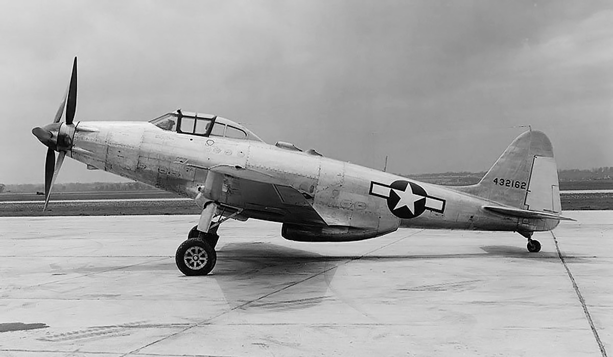
The Spiteful prototype (NN664) is considered the first true Spiteful because it incorporated the new fuselage. The aircraft was never painted. Note the standard, Spitfire F.21 tail.

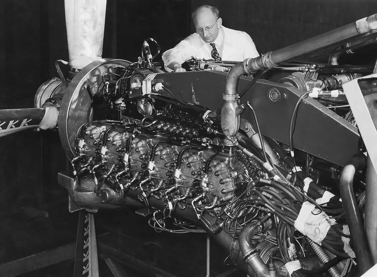
The Spiteful’s Mark numbers were a continuation of those used on the Spitfire. The Spiteful F.XIV (F.14) was powered by a 2,375 hp (1,771 kW) Rolls-Royce Griffon 69 with a five-blade, single-rotation propeller. The Spiteful F.XV (F.15) was powered by the 2,350 hp (1,752 kW) Griffon 89 or 90 with a six-blade, contra-rotating propeller. Both Griffon engines had a two-stage, two-speed supercharger, and both the five- and six-blade propellers were 11 ft (3.35 m) in diameter and built by Rotol. Originally, a Rolls-Royce Merlin engine could be substituted for the Griffon if Griffon engine production was found to be lacking, but the Merlin option was dropped in mid-1944.

The Spiteful had a 35 ft (10.67 m) wingspan, was 32 ft 11 in (9.76 m) long, and was 13 ft 5 in (4.10 m) tall. The aircraft had a maximum speed of 409 mph (658 km/h) at sea level, 437 mph (703 km/h) at 5,500 ft (1,676 m), and 483 mph (777 km/h) at 21,000 ft (6,401 m). Cruising speed for maximum range was 250 mph (402 km/h) at 20,000 ft (6,096 m). The Spiteful’s stalling speed was 95 mph (153 km/h). The aircraft’s range was 564 mi (908 km) on internal fuel and 1,315 mi (2,116 km) with drop tanks. The Spiteful had an empty weight of 7,350 lb (3,334 kg), a normal weight of 9,950 lb (4,513 kg), and a maximum weight of 11,400 lb (5,171 kg). The aircraft had an initial rate of climb of 4,890 fpm (24.8 m/s) and a ceiling of 42,000 ft (12,802 m).

Supermarine Spiteful NN667 and RB523 long scoop

A comparison of the third Spiteful prototype (NN667) and the ninth F.XIV production aircraft (RB523). Both have the elongated intake scoop mounted under the engine and just behind the spinner. Note the larger tail compared to the first two Spiteful prototypes.

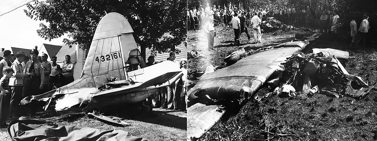
With other war work taking priority, it was some time before Supermarine had anything related to the Spiteful to test. A mockup was inspected in March 1944, and the aircraft’s name was changed to Spiteful around this time. A set of wings was fitted to a Spitfire XIV (serial number NN660), which became the first Spiteful prototype. The aircraft was first flown on 30 June 1944, with Jeffrey Quill as the pilot. The aircraft used the same 2,035 hp (1,518 kW) Griffon 61 engine as installed in a standard Spitfire XIV, but its performance was superior to that of a standard Spitfire XIV. However, the Spiteful also exhibited rather violent stalling characteristics compared to the fairly docile stall of the Spitfire. This was attributed to the outer wing with the aileron stalling first, which was the opposite of how the Spitfire’s elliptical wing stalled. With the Spitfire, the outer wing stalled last and enabled the ailerons to remain effective deep into the stall. On 13 September 1944, NN660 crashed while engaged in a dog-fight test with a standard Spitfire XIV. The pilot, Frank Furlong, was killed in the crash. A definitive cause was never determined, but it was believed that the aileron control rods became jammed during moderate G maneuvers.

On 8 January 1945, the second Spiteful prototype (NN664) took to the air, piloted by Quill. The aircraft incorporated updated aileron controls and the new Spiteful fuselage. However, NN664 had a tail similar to that used on the Spitfire F.21. Extensive handling tests were undertaken on NN664 that resulted in a few changes. The most significant change was a redesigned tail with its vertical stabilizer and rudder area increased by 28 percent and its horizontal stabilizer and elevator area increased by 27 percent. NN664 first flew with the new tail on 24 June 1945, and the aircraft was sent to the Aeroplane and Armament Experimental Establishment (A&AEE) at RAF Boscombe Down for flight trials.

Supermarine Spiteful RB515 underside

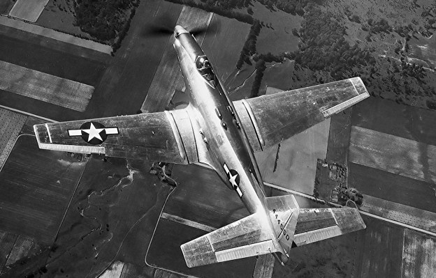
The underside of Spiteful RB515, the first production aircraft, illustrates the wings’ straight leading and trailing edges. Note the standard, short intake scoop. Outlines of the radiator housing doors are visible.

Shortly after NN664’s first flight, the Air Ministry ordered 650 Spiteful aircraft. The order went through a number of reductions, including the cancellation of 150 Spitefuls around 5 May 1945 so that a comparable number of Seafangs (see below) could be ordered. The fourth prototype was included in these cancellations.

The third Spiteful prototype (NN667) was sent to the A&AEE for service evaluations on 1 February 1946. It was found that the aircraft exhibited several areas of poor build quality, and there were numerous concerns with its ease of serviceability. A multitude of fasteners needed to be undone in order to remove the engine cowling, and rearming the aircraft was a time-consuming process that involved disconnecting the controls to the ailerons. A number of modifications and improvements were suggested, but it is not clear just how many were implemented. For at least part of its existence, NN667 had an elongated air intake that would be featured on the Seafang (see below). Other Spitefuls also had the longer scoop (at least RB517, RB518, RB522 and RB523).

The first production Spiteful F.XIV (RB515) made its first flight on 2 April 1945, with Quill in the pilot’s seat. The aircraft originally had an F.21 tail, but a larger Spiteful tail was installed after RB515’s third flight, which ended in a forced landing. The aircraft’s first flight with the new tail was on 21 May 1945. On 27 September 1945, RB515 suffered an engine failure and made another forced landing at Farnborough. The damaged aircraft was subsequently written off.

Supermarine Spiteful RB515 in flight

Another view of RB515 illustrates the larger Spiteful tail that was later applied to the Spitfire F.22 and F.24. The tail improved the Spiteful’s handling, but the aircraft’s stall was still violent compared to the Spitfire’s.

Spiteful RB518 was fitted with a rounded Seafang (see below) windscreen and a 2,420 hp (1,805 kW) Griffon 101 engine to become the sole Spiteful F.XVI (F.16). The Griffon 101 had a two-stage, three-speed supercharger and turned a five-blade, single rotation propeller. In 1947, RB518 achieved 494 mph (795 km/h) at 27,800 ft (8,473 m), the highest level-flight speed recorded by a British piston-powered aircraft. Testing of this aircraft with not-fully-developed engines resulted in seven forced landings—the last was at Chilbolton in March 1949 and resulted in the landing gear being pushed through the wings. The aircraft was then dropped by the recovery crane, ending any hope of repair.

By February 1946, the Spiteful order had been reduced to 80 aircraft. This was again reduced on 22 May 1946 to 22 aircraft, and the Spiteful order finally dropped to 16 aircraft on 16 December 1946. The production order basically covered the aircraft that had been built, although some of the last aircraft may not have flown. A 17th Spiteful, RB520 (the sixth production aircraft), was handed over to the FAA for Seafang (see below) development on 22 September 1945. The aircraft was modified for carrier feasibility trials with a “stinger” arrestor hook incorporated into a special housing below the rudder. RB520 retained the standard, non-folding Spiteful wings.

Supermarine Spiteful RB518

Powered with a two-stage, three-speed Griffon 101 engine, Spiteful RB518 achieved a level-flight speed of 494 mph (795 km/h), the highest recorded by a British piston-powered aircraft. RB518 was the only F.XVI Spiteful and was subsequently written off after its seventh forced landing.

The production aircraft were serialed RB515 to RB525, RB527 to RB531, and RB535. The final Spiteful was delivered on 17 January 1947. Of the three Spiteful prototypes and 17 production aircraft, most were sold for scrap in July 1948. It appears RB518 was the last Spiteful to fly, and no examples of the type survive. The larger “Spiteful tail” was incorporated into the last Spitfires, the F.22 and F.24.

The Spiteful’s cancellation was based on a number of realities including the more impressive performance of jet aircraft, the end of World War II, and serviceability questions about the Spiteful. While the Spiteful’s speed was impressive, it was below the 504 mph (811 km/h) that was originally estimated. Furthermore, the performance of the aircraft’s laminar wing decreased substantially if there were imperfections, including smashed bugs, on the leading edge. It was unlikely that an in-service warplane would be free of all imperfections.

Supermarine Spiteful RB520

Spiteful RB520 was loaned out for Seafang development and is considered by some as a Seafang prototype. Note the tail hook housed below the rudder and the “Royal Navy” stenciling on the fuselage.

Back in October 1943, Supermarine designed the Type 382, which was basically a navalized Spiteful. The design had started with mounting a Spiteful-type, laminar flow wing on a Seafire XV. Little official interest was given to the project until 21 April 1945, when the Air Ministry issued Specification N.5/45 for a single-seat fighter for the FAA. Subsequently, Supermarine was awarded a contract for two prototype Type 382 fighters, which became the Seafang. An order for 150 Seafang aircraft was placed on 7 May 1945; this order was essentially a reallocation of Spiteful aircraft that had been cancelled around two days prior.

The production Seafang closely matched the Spiteful but incorporated wings designed so that the last four feet folded vertically. The folding mechanism was hydraulically-powered. The Seafang had an elongated carburetor intake scoop, with the opening just behind the propeller. The aircraft also had a rounded front windscreen rather than the flat plate used on the Spiteful. Under the rudder was a stinger tail hook for catching the arresting cables on the carrier deck. The Seafang’s landing gear was re-enforced to handle carrier operations. The fuel tank behind the cockpit was reduced to 54 gal (45 imp gal / 205 L), resulting in a total internal capacity of 193 gal (161 Imp gal / 732 L).

Supermarine Seafang VG471 front

The first production Supermarine Seafang F.31 (VG471) was essentially a Spiteful with arrestor gear. All F.31 aircraft had standard, non-folding wings. Note what appears to be a wide-cord propeller.

Like the Spiteful, two Seafang variants were planned. The F.31 used the 2,375 hp (1,771 kW) Griffon 69 engine with a five-blade, single-rotation propeller, while the F.32 used the 2,350 hp (1,752 kW) Griffon 89 with a six-blade, contra-rotating propeller. The F.31 was basically a Spiteful with an arrestor hook and did not incorporate folding wings. The F.31s would serve as a test aircraft while the F.32 was being developed.

The Supermarine Seafang had a 35 ft (10.67 m) wingspan, was 34 ft 1 in (10.39 m) long, and was 12 ft 7 in (3.84 m) tall. With wings folded, the span was reduced to 27 ft (8.23 m). The aircraft had a maximum speed of 397 mph (639 km/h) at sea level, 428 mph (689 km/h) at 5,500 ft (1,676 m), and 475 mph (764 km/h) at 21,000 ft (6,401 m). Cruising speed for maximum range was 250 mph (402 km/h) at 20,000 ft (6,096 m). The aircraft’s range was 393 mi (632 km) on internal fuel. The Seafang weighed 8,000 lb (3,629 kg) empty, 10,450 lb (4,740 kg) with a normal load, and 11,900 lb (53,98 kg) maximum. The aircraft had an initial rate of climb of 4,630 fpm (23.5 m/s) and a ceiling of 42,000 ft (12,802 m).

Supermarine Seafang VG471

The side view of Seafang VG471 illustrates many of the aircraft’s features: long intake scoop, straight wing edges, radiator scoop doors, rounded windscreen, bubble canopy, large tail, and arrestor hook.

As previously mentioned, some Spitefuls had the long intake carburetor scoop; RB518 had a Seafang windscreen; and RB520 was fitted with an arrestor hook (resulting in some sources classifying it as a Seafang prototype). This was all done to lead up to Seafang F.31 production aircraft, which were basically Spitefuls with arrestor hooks. The first Seafang F.31 was VG471, which followed the fifth Spiteful off the production line. All of the F.31s had the five-blade propeller, lacked folding wings, and would end up the only production Seafangs that were completed. VG471 was first flown in early January 1946 and used in arrestor hook trials. The original hook installation proved to be weak, and a redesigned system was installed in March 1946. The aircraft passed the trials on 1 May.

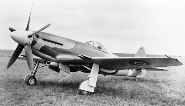
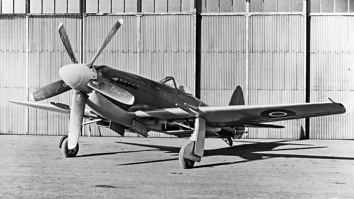
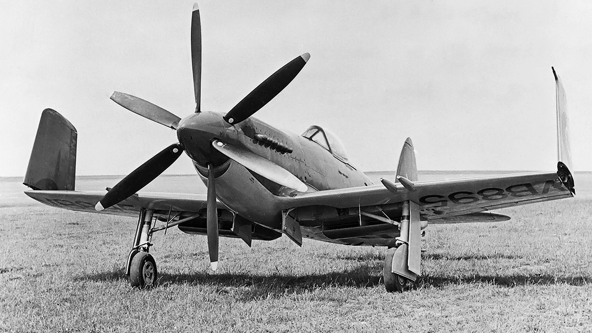
The prototype Seafang F.32s were serial numbers VB893 and VB895, and both had contra-rotating propellers and folding wings. VB895 was first flown in early 1946 and was delivered to the A&AEE on 30 June. In August 1946, VB895 was demonstrated separately to the Royal Netherlands Navy, French representatives, and United States representatives in an attempt to sell the Seafang to allies. However, no orders were placed. In May 1947, test pilot Mike Lithgow successfully performed deck trials in VB895 on the HMS Illustrious. The aircraft’s wide track landing gear drastically increased its stability while on the ground, and the contra-rotating propeller eliminated the torque effect. VB895 was also tested with a single, fuselage-mounted 204 gal (170 Imp gal / 773 L) drop tank, and the aircraft was used for armament trials. During a static test firing of the cannons on 18 May 1948, a build-up of gases in the left wing resulted in an explosion that damaged the wing. Extra vents were added, and no further issues occurred.

Supermarine Seafang VB895

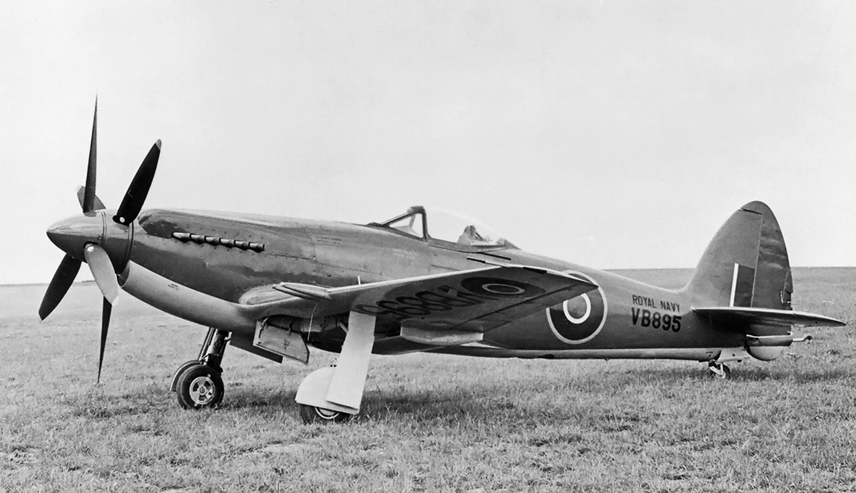
The Seafang F.32 prototype VB895 was the first fully-navalized aircraft of the series. The contra-rotating propellers eliminated the torque effect that led to the downfall of many aviators, especially when operating from the short deck of an aircraft carrier.

While praised for its handling and responsiveness, the Seafang did not offer any real advantage over the Seafire 47, and the Seafang’s stall was certainly a disadvantage. An order was subsequently placed for the Seafire. The original interest in the Seafang was based on doubts regarding the suitability of jet aircraft for carrier operations. As those doubts faded, so did interest in the Seafang, and the aircraft was cancelled. A few Seafangs were kept active for a brief time to continue evaluating the laminar flow wing, which was used on the Supermarine Type 392 Attacker. The Attacker was often referred to as a “Jet Spiteful,” although it had Seafang folding wings with the radiators removed and additional fuel tanks installed. The Attacker first flew on 27 July 1946, and it was the first jet fighter to enter operational service with the FAA.

Eighteen production Seafangs were built, carrying serial numbers VG471 to VG490. The first 10 aircraft were F.31s, and the remaining eight were F.32s. However, only the first eight or so aircraft were completed, with the remaining units delivered disassembled. Sadly, like the Spiteful, all of the Seafang examples were scrapped.

Note: The Royal Air Force and Fleet Air Arm used Roman numerals for mark numbers up thorough 1942. From 1943 through 1948, the Roman numerals were phased out for new aircraft, and Arabic numerals were applied. From 1948 onward, Arabic numerals were used exclusively. The Spitefuls were typically referred to using Roman numerals, but the slightly later Seafang used Arabic numerals. The use of both Roman and Arabic numerals in this article refers to the most common use applied for the particular aircraft type.

Supermarine Seafang VB895 wings folded

The folding wings on Seafang VB895 were hydraulically operated and decreased the aircraft’s wingspan by 8 ft (2.4 m). Although, the wide tack landing gear contributed to snaking at low speeds, it enhanced the stability at higher speeds and as the aircraft slammed down on a carrier deck.

Sources:
Spitfire: The History by Eric B. Morgan and Edward Shacklady (2000)
British Experimental Combat Aircraft of World War II by Tony Buttler (2012)
Supermarine Aircraft since 1914 by C.F. Andrews and E.B. Morgan (1981)
Ultimate Spitfires by Peter Caygill (2006)
Supermarine Fighter Aircraft by Victor F. Bingham (2004)
Griffon-Powered Spitfires by Kev Darling (2001)
Fighters: Volume Two by William Green (1961)
Interceptor Fighters for the Royal Air Force 1935–45 by Michael J.F. Bowyer (1984)
Spitfire: A Complete Fighting History by Alfred Price (1992)
Wings of the Weird & Wonderful by Captain Eric Brown (2012)

Farman 18T engine

Farman 18T 18-Cylinder Aircraft Engine

By William Pearce

The rules of the Schneider Trophy Contest stated that any country that won the contest three consecutive times would retain permanent possession of the trophy. By 1930, Britain had two consecutive victories and were favored to win the next contest scheduled for September 1931. Frenchman Jacques P. Schneider had started the contest, and France won the first competition held in 1913. The possibility of losing the contest forever spurred France to action, and the STIAé (service technique et industriel de l’aéronautique, or the Technical and Industrial Service of Aeronautics) ordered at least five aircraft types and three different engines for the 1931 contest. One of the engines ordered was the Farman 18T.

Farman 18T engine

The Farman 18T was specifically designed for installation in the Bernard flying boat. The unusual 18-cylinder engine had no other known applications.

Avions Farman (Farman) was founded in 1908 by brothers Richard, Henri, and Maurice. In October 1917, the company moved to produce engines built under license to support the war effort. The first of these engines was built in mid-1918, and production stopped after World War I. In 1922, Farman started to design their own line of engines under the direction of Charles-Raymond Waseige.

The Farman 18T was designed by Waseige and had an unusual layout. The water-cooled engine had three cylinder banks, each with six cylinders. The left and right cylinder banks were horizontally opposed, with a 180-degree flat angle across the engine’s top side. The lower cylinder extended below the crankcase and was perpendicular to the other cylinder banks. This configuration gave the 18-cylinder engine a T shape.

The engine used a two-piece cast aluminum crankcase that was split vertically. Steel cylinder liners were installed in the cast aluminum, monobloc cylinder banks that were bolted to the crankcase. The four valves of each cylinder were actuated via pairs of rockers by a single overhead camshaft. Each camshaft was driven by a vertical shaft at the rear of the engine.

The 18T used aluminum pistons and had a compression ratio of 6.0 to 1, although some sources say 8.5 to 1. The connecting rods consisted of a master rod for the lower cylinder bank and two articulated rods for the left and right cylinder banks. Each cylinder had two spark plugs, one installed in each side of the cylinder bank. The spark plugs were fired by magnetos driven from the rear of the engine. A nose case at the front of the engine contained the Farman-style bevel propeller reduction gear that turned the propeller at .384 crankshaft speed.

Farman 18T Paris Air Show 1932

The 18T (lower left) was proudly displayed as part of the Farman exhibit at the Salon de l’Aéronautique in November 1932. The other Farman engines are a 350 hp (261 kW) 12G (middle) and a 420 hp (313 kW) 12B (right).

For induction, air passed through carburetors at the rear of the engine and into a centrifugal supercharger that provided approximately 4.4 lb (.3 bar) of boost. The air/fuel mixture flowed from the supercharger into an intake manifold for each cylinder bank. The intake manifolds ran along the bottom of the cylinder bank for the left and right banks and along the right side (when viewed from the non-propeller end) of the lower cylinder bank. The exhaust ports were on the opposite side of the cylinder head from the intake.

The 18T had a 4.72 in (120 mm) bore and stroke. The engine displaced 1,491 cu in (24.4 L) and produced a maximum of 1,480 hp (1,104 kW) at 3,700 rpm. The 18T was rated at 1,200 hp (895 kW) at 3,400 rpm for continuous output. The engine was 65.98 in (1.68 m) long, 44.65 in (1.13 m) wide, 32.56 (.83 m) tall, and weighed 1,069 lb (485 kg).

Two Farman 18T engines were ordered under Contract (Marché) 289/0 (some sources state Marché 269/0) issued in 1930 and valued at 3,583,000 Ғ. The two engines were to power a flying boat built by the Société des avions Bernard (Bernard Aircraft Company). An official designation for the flying boat has not been found, and it was not among the known aircraft ordered for the 1931 Schneider Contest. There is some speculation that a lack of funds prevented the aircraft from being ordered for the 1931 race, but it would be ordered in time for the 1933 race.

Farman 18T Paris Air Show 1932 display

The display at the air show in Paris announced the 18T’s 1,200 hp (895 kW) continuous rating. Note that the supercharger housing extended above the crankcase, which was otherwise the engine’s highest point.

The design of the Bernard flying boat was led by Roger Robert and developed in coordination with the 18T engine. The all-metal aircraft had a low, two-step hull with sponsons protruding from the sides, just behind the cockpit. A long pylon above the cockpit extended along the aircraft’s spine, and the pylon supported the engine nacelle and wings. The engines were installed back-to-back in the middle of the nacelle. The engines’ lower cylinder banks extended into the pylon, and the left and right cylinder banks extended into the cantilever wings, which were mounted to the sides of the nacelle. Surface radiators for engine cooling covered the sides of the pylon, and extension shafts connected the propellers to the engines. The aircraft had a 36 ft 1 in (11.0 m) wingspan and was 35 ft 5 in (10.8 m) long. The engine nacelle was 17 ft 1 in (5.21 m) long. A 12.5 to 1 scale model of the flying boat was tested at the Laboratoire Aérodynamique Eiffel (Eiffel Aerodynamics Laboratory) in Auteuil (near Paris), France.

The 18T engines were bench tested in 1931, but the most power achieved was only 1,350 hp (1,007 kW). While further development was possible, at the time, the chance of France fielding a contestant in the 1931 Schneider Contest was virtually non-existent. The chances of the Bernard flying-boat being built were even worse. Although the aircraft had an estimated top speed of over 435 mph (700 km/h), and a detailed study was submitted to the Service Technique (Technical Service), the flying boat was seen as too radical and was never ordered. The limited funds were needed for the more conventional racers.

The Supermarine S.6B went on to win the 1931 Schneider Contest, giving the British permanent possession of the trophy. The 18T was marketed in 1932 and displayed at the Paris Salon de l’Aéronautique (Air Show) in November. However, there was little commercial interest in the 18T, and the project was brought to a close without the engine ever being flown; most likely, full testing was never completed.

Bernard - Farman 18T Schneider 3-view

Powered by two 18T engines, the Bernard flying boat racer had an estimated top speed of over 435 mph (700 km/h). This speed was substantially faster than the Supermarine S.6B that won the 1931 Schneider race at 340.08 mph (547.31 km/h) and went on to set an absolute speed record at 407.5 mph (655.8 km/h). However, the estimated specifications of unconventional aircraft often fall short of what is actually achieved.

Sources:
Aerosphere 1939 by Glenn D. Angle (1940)
Les Moteurs a Pistons Aeronautiques Francais Tome 1 by Alfred Bodemer and Robert Laugier (1987)
Schneider Trophy Seaplanes and Flying Boats by Ralph Pegram (2012)
Les Avions Bernard by Jean Liron (1990)
Les Avions Farman by Jean Liron (1984)

Napier-Deltic-T18-37K-Marine-Engine

Napier Deltic Opposed-Piston Diesel Engine

By William Pearce

In 1933, the British engineering firm D. Napier & Son (Napier) acquired licenses to produce the Junkers Jumo 204 and 205 aircraft engines. Napier sought to diversify and expand its aircraft engine business, and the company felt the two-stroke, opposed-piston, diesel engines would usher in an era of safe and fuel-efficient air travel. Napier made some modifications to the Jumo engines, but the internal components were mostly unchanged. The Jumo 204 was built as the Napier Culverin (E102), and the Jumo 205 was planned as the Napier Cutlass (E103). The Culverin was first run on 24 September 1934, but the engine garnered little interest and no orders. By 1936, after only seven Culverins were made and no Cutlasses, Napier halted further work on opposed-piston diesel aircraft engines. English Electric took over Napier in November 1942.

Napier-Deltic-E130-Three-cylinder-test-engine

The Napier E130 three-cylinder test engine that validated the triangular engine arrangement. Each of the engine’s crankshafts had a flywheel on the drive end (left). The six intake chamber openings are visible on the free (non-drive) end (right). Note the vertical coolant pipes on top of the engine. (Napier/NPHT/IMechE images)

In 1944, the British Admiralty desired to increase the survivability of the Motor Torpedo Boat (MTB). One of the main issues was that MTBs used gasoline engines. Gasoline liquid is highly flammable, and gasoline vapor is highly explosive. MTB safety would be improved if a switch to diesel engines could be made. Diesel fuel has non-explosive characteristics and a much higher flashpoint than gasoline. However, at the time, there were no suitable diesel engines to power MTBs.

Around 1945, Napier and other companies submitted proposals to the Admiralty for a light-weight, powerful, and compact 18-cylinder diesel engine. Napier’s new engine carried the company designation E130, and the design was influenced by their experience with the Junkers Jumo diesel engines, their work on the Culverin and Cutlass, and analyses of other Jumo six-cylinder engines captured during World War II. However, there is no mention of the Junkers Jumo 223 contributing to Napier’s engine design. In early 1946, the Admiralty selected the Napier design and issued a developmental contract that covered the construction of one single-cylinder test engine, one three-cylinder test engine, and six prototype 18-cylinder engines.

Napier-Deltic-drive-end-section

Section drawing from the drive end of a Deltic engine. The air chamber surrounds the intake end of the cylinder, and the exhaust manifolds are mounted to the outer sides of the engine. Note the rotation of the crankshafts. (Napier/NPHT/IMechE image)

Napier’s liquid-cooled, two-stroke engine used opposed-pistons, a design feature that eliminated many parts, required no cylinder head, improved thermal efficiency, and resulted in more power for a given size and weight. In an opposed-piston engine, each cylinder has two pistons that move toward each other to form a single combustion space near the center of the cylinder. Ports in the cylinder wall that are covered and uncovered by the pistons bring in air and allow exhaust gases to escape. The most unusual aspect of Napier’s design was that the engine was formed as an inverted triangle, with a crankshaft at each corner. Because of its triangular structure, the name Deltic was selected in reference to the Greek letter Delta, and the 18-cylinder engine was known as the Deltic D18 (or just 18). The triangular design resulted in a compact engine with a very rigid structure.

Design work on the Napier Deltic started under Ben Barlow, George Murray, and Ernest Chatterton, Chief Engineer of the Piston Engine Division at Napier. The project was initially overseen by Henry Nelson, with Herbert Sammons taking over in 1949. The Deltic engine formed an equilateral triangle with each of its three cylinder banks angled at 60 degrees. Cast aluminum crankcase housings were at each corner of the triangle, with the lower crankcase incorporating an oil sump and also serving as the engine’s base. Each cast aluminum cylinder bank was sandwiched between two crankcases via through bolts. The monobloc cylinder banks were identical, as were the upper two crankcases. However, various ancillary components were installed according to the casting’s position on the complete engine.

Napier-Deltic-18-Triangle-Case

The assembled cylinder banks and crankcases of an 18-cylinder Napier Deltic engine seen from the free end. Note the open space between the cylinder banks. The stadium (oval) ports are to the air chambers. The bushings visible in the upper crankcases, at the triangle’s corners, supported the shafts that drove the blower. (Napier/NPHT/IMechE image)

The forged-steel cylinder wet liners were open-ended and had a chrome-plated bore to reduce wear. Part of the bore was etched with small dimples to retain lubricating oil and reduce piston ring wear. The liner was approximately 32 in (813 mm) long and protruded some distance into the crankcases. The ends of the liner were notched to allow clearance for the swinging connecting rods. Near one end of the liner were 14 intake ports with a tangential entry to impart a swirling motion of the incoming air. The swirling air helped scavenge the cylinder through the nine exhaust ports near the other end of the liner. In each cylinder, one piston would cover and uncover the intake ports while the other piston would do the same for the exhaust ports. The exhaust ports were uncovered (opened) 34.5 degrees before the intake ports. Both sets of ports were uncovered (open) for 101.5 degrees, and the intake ports were uncovered (open) for 5.5 degrees after the exhaust ports were covered (closed). The placement of the intake and exhaust ports at opposite ends of the cylinder liner allowed for uniflow scavenging of the cylinder. The liners were shrink-fitted into the cylinder banks and secured by an annular nut on the intake side.

The two-piece pistons consisted of a cast aluminum outer body and a forged Y-alloy (nickel-aluminum alloy) inner member that held the wrist pin. The inner member was heat-shrunk to the outer piston body and secured by a large circlip. Oil flowed between the two pieces to cool the piston. Three compression rings were positioned just below the piston crown, and two oil scraper rings were located near the bottom of the piston skirt. The pistons were attached to fork-and-blade connecting rods, with the exhaust pistons mounted to the forked rods and the intake pistons mounted to the blade rods. The opposed pistons created a compression ratio of 17.5 to 1 (some sources say 15 to 1).

Napier-Deltic-assembly

Napier Deltic engine assembly, with phasing gear housings being built up in the lower right. At left is a completed phasing gear housing; note the two idler gears connecting the lower crankshaft to the central output shaft. Toward the center are Deltics in various stages of assembly. A completed engine without its blower installed is in the upper right. Note the opening in the center of the engine. (Napier/NPHT/IMechE image)

A two-piece phasing gear housing at the drive end of the engine contained the gears that connected the crankshafts to the main output shaft. The main output shaft was usually located at the center of the engine, but different phasing gear housings allowed for different output shaft locations. Each crankshaft was coupled to its drive gear via a short, flexible quill shaft. When viewed from the free (non-drive) end of the engine, the upper two crankshafts rotated clockwise and were connected to the main output shaft via one idler gear. The lower crankshaft rotated counterclockwise and was connected to the main output shaft via two idler gears. The idler gears could be repositioned to reverse the rotation of the output shaft. Each crankshaft was supported in its crankcase by seven main bearings, and each main bearing cap was secured by four studs and two transverse bolts. The crankshafts were phased so that the exhaust piston in each cylinder led the intake piston by 20 degrees. The reverse rotation of the lower crankshaft, and the crankshaft phasing was devised by Herbert Penwarden from the Admiralty Engineering Laboratory.

Via a quill shaft and bevel gears, each crankshaft also drove a camshaft for the fuel injection pumps. The camshaft was located in a housing bolted to the outer side of each cylinder bank, near its center. Each camshaft operated six fuel injection pumps, and each pump fed fuel to two injectors per cylinder. The timing of the pumps changed depending on engine RPM. The upper two crankshafts drove separate flexible drive shafts for the blower (weak supercharger). The driveshafts were positioned at the upper, inner corners of the engine triangle. They led to the opposite end of the engine and powered a single-stage, double-sided centrifugal blower. The impeller was 15.5 in (394 mm) in diameter and rotated at 5.72 times crankshaft speed, creating 7.8 psi of boost (.53 bar). The pressurized air from the blower was fed into a chamber that extended through each cylinder bank and that surrounded the intake ports in the cylinder liner. Exhaust gases were collected via a water-cooled manifold that attached to the outer side of each cylinder bank. The lower crankshaft drove a flexible drive shaft to power the engine’s two oil and two water pumps.

Napier-Deltic-T18-37K-sections-display

Basic sections of the Deltic (T18-37K) marine engine. From left to right are the blower section (turbo-blower in this case), D18-cylinder engine section, phasing gear housing, and the bi-directional gearbox. The Deltic was a powerful diesel engine for its size and weight. (Napier/NPHT/IMechE image)

When viewing the engine from the free end, the cylinder banks were designated as follows: left was Bank A; upper, horizontal was Bank B; and right was Bank C. The crankshafts were designated as follows: upper left was Crankshaft AB, upper right was Crankshaft BC, and lower was Crankshaft CA. The cylinder rows were numbered with Bank 1 at the free end, and subsequent banks were numbered consecutively with Bank 6 at the drive end. The Deltic D18’s firing order was Bank C cylinder 1 (C1), A6, B1, C5, A1, B5, C3, A5, B3, C4, A3, B4, C2, A4, B2, C6, A2, and B6.

The Napier Deltic had a 5.125 in (130 mm) bore and a 7.25 in (184 mm) stroke (x2). This gave each cylinder a displacement of 299 cu in (4.9 L), and the 18-cylinder engine displaced 5,384 cu in (88.2 L). The bare engine (without the bi-directional marine gearbox) had a maximum, 15-minute output of 2,730 hp (2,036 kW) at 2,000 rpm with a specific fuel consumption (sfc) of .380 lb/hp/hr (231 g/kW/h). The Deltic’s continuous rating was 2,035 hp (1,517 kW) at 1,700 rpm with a sfc of .364 lb/hp/hr (221 g/kW/h). With the bi-directional gearbox, the engine produced 2,500 hp (1,864 kW) at 2,000 rpm with a sfc of .415 lb/hp/hr (252 g/kW/h) and 1,875 hp (1,398 kW) at 1,700 rpm with a sfc of .395 lb/hp/hr (240 g/kW/h). The Deltic D18 was 105 in (2.67 m) long, 71.25 in (1.81 m) wide, and 80 in (2.03 m) tall. The bi-directional gearbox added another 36 in (.91 m). The engine weighed 8,860 lb (4,018 kg) without the bi-directional gearbox and 10,500 lb (4,763 kg) with it.

The single-cylinder test engine was designed from October to December 1946, with the three-cylinder engine following from January to May 1947. Testing of these engines started as soon as construction was completed. The three-cylinder engine represented just one row of a Deltic engine, but it demonstrated the validity of the components used in the triangular arrangement.

Napier-Deltic-D18-E130-Prototype

Free end of the 2,500 hp (1,864 kW) Deltic D18-1 (E130) prototype engine. Note the two intakes, one for each side of the double-sided blower. Each cylinder bank had two, large exhaust manifolds. The transverse bolts threaded into the main bearings can be seen on the side of the upper crankcase. (Napier/NPHT/IMechE image)

The first 18-cylinder Deltic Series I engine was assembled by March 1950. The engine was soon to be tested at Napier’s works in Acton, England; however, a cable broke as the engine was being mounted to the stand. It fell on the stand, damaging the engine and the test stand. Repairs were made, and engine began testing in April 1950. The 18-cylinder Deltic fired a cylinder every 20 degrees of crankshaft rotation, which resulted in smooth, nearly-constant output torque. Engine idle was around 600 rpm, and the Deltic demonstrated a gross mechanical efficiency of 85.5% at 2,000 rpm. In late 1951, two Deltics were installed in place of the three Mercedes-Benz MB 501 V-20 engines in a former German E-boat S-212 (redesignated Fast Patrol Boat P5212). By January 1952, the originally-contracted six Deltic D18 engines had been built. In 1953, an Admiralty 1,000-hr type test was completed and indicated the engine could run 2,000 hours between overhauls.

By 1954, Napier was offering a commercial version of the Deltic D18 Series I (E169). This was basically a de-rated engine. The commercial engine produced 1,900 hp (1,417 kW) at 1,500 rpm with a sfc of .363 lb/hp/hr (221 g/kW/h) and could operate for 5,000 hours between overhauls. In addition to a variety of marine applications, Deltic engines could also run power generation sets, water pumps, and be used to power traction motors for locomotives. Napier also built a nine-cylinder version with three banks of three cylinders. The Deltic 9 (E159/E165) displaced 2,692 cu in (44.1 L) and had a one-sided centrifugal blower but was otherwise of the same construction as the Deltic D18. It fired one cylinder for every 40 degrees of crankshaft rotation. Maximum output for the Deltic 9 was 1,250 hp (932 kW) at 2,000 rpm for the high-power version and 950 hp (708 kW) at 1,500 rpm for the commercial version. By late 1955, Deltic test and production engines had accumulated over 20,000 hours of operation.

Napier-Deltic-C18-5-Compound-Marine-Engine

The 5,500 hp (4,101 kW) compound Deltic C18 (E185) engine was the most powerful piston engine Napier ever built. Although it is covered, the intake can be seen in the upper part of the phasing gear housing. Exhaust was routed through the three-stage turbine, which powered the eight-stage compressor inside the engine’s triangle. (Napier/NPHT/IMechE image)

In 1956, Napier built a compound diesel engine known as the Deltic C18 (E185). Serious development of the C18 occurred after the Napier Nomad II compound diesel aircraft engine was cancelled in 1955. The Deltic C18 had an eight-stage (some sources say 12-stage, which was the same number of stages as used in the Nomad II) axial compressor positioned inside the engine triangle. The compressor was driven by a three-stage turbine, which was powered by the engine’s exhaust gases. The turbine was positioned in the normal blower position on the free end of the engine. A new phasing gear housing was constructed with an opening that allowed air into the center of the engine triangle and served as the inlet for the compressor. The Deltic C18 produced 5,500 hp (4,101 kW) at 2,000 rpm. The engine was 124 in (3.15 m) long, 65 in (1.65 m) wide, and 77 in (1.96 m) tall. The C18 weighed approximately 10,700 lb (4,853 kg). The engine was tested in 1957, but only one experimental C18 was built. While undergoing power tests, the engine was intentionally pushed beyond its limits until a connecting rod failed at 5,600 hp (4,176 kW). The rod came through the crankcase, but the damage was never repaired due to the Navy’s increased focus on gas turbine engines.

By 1956, Napier had introduced some minor changes as the Series II Deltic engines, but one major change was the addition of a turbo-blower. These engines were known as turbo-blown, and they were designated as the Deltic T18 (E171/E239). Exhaust gases were collected and fed into an axial-flow turbine mounted behind the blower. The turbine wheel was 18.04 in (458 mm) in diameter and helped turn the blower via a geared shaft. The turbine wheel turned at .756 times the speed of the blower impeller. The blower was still driven by the upper crankshafts, but it now turned at 8.266 times crankshaft speed. The turbo-blower created 19 psi (1.31 bar) of boost. The piston was redesigned and consisted of three-pieces: a Hidural 5 (copper alloy) crown that screwed onto an aluminum skirt to form the outer body, and a Y-alloy (nickel-aluminum alloy) inner member that held the wrist pin. A third scraper ring was added to the piston skirt. The compression ratio was increased to 17.9 to 1, and the engine used one fuel injector per cylinder. The Deltic T18 had an output of 3,100 hp (2,312 kW) at 2,100 rpm and 2,400 hp (1,641 kW) at 1,800 rpm. SFC was .414 lb/hp/hr (252 g/kW/h) and .404 lb/hp/hr (246 g/kW/h) respectively. The engine was 118 in (3.00 m) long, 75 in (1.91 m) wide, and 84 in (2.13 m) tall. The T18 weighed around 13,630 lb (6,183 kg) with the bi-directional gearbox and 11,050 lb (5,012 kg) without it. The turbo-blown nine-cylinder Deltic T9 (E172/E198) produced 1,100 hp (820 kW) at 1,600 rpm.

Napier-Deltic-T18-37K-Marine-Engine

The 3,100 hp (2,312 kW) turbo-blown Deltic T18-37K (E239) engine was most widely used in Motor Torpedo Boats. Note the exhaust manifolds leading to the turbine with its large intake at the rear of the engine. The short duct connecting the blower to the upper cylinder bank is visible. (Napier/NPHT/IMechE image)

More changes were incorporated into the Series III engines, which also introduced charge-cooling with the Deltic CT18 (E263) in 1966. For the CT18, a single drive shaft passed through the center of the engine to deliver power from the phasing gear housing to the turbo-blower. The shaft turned at 5.16 times crankshaft speed, and both the blower impeller and turbine wheel were mounted to the drive shaft. The single-sided blower impeller was relocated to behind the turbine wheel. A water-filled aftercooler was mounted before each opening of the engine’s three air compartments. The aftercooler dropped the charge temperature from 259° F (126° C) to 144° F (62°C). Pistons were again redesigned, with the Hidural 5 (copper alloy) crown bolting to the aluminum skirt. For the Deltic CT18, power increased to 3,700 hp (2,759 kw) at 2,100 rpm with a sfc of .403 lb/hp/hr (245 g/kW/h) and 2,750 hp (2,051 kW) at 1,800 rpm with a sfc of .395 lb/hp/hr (240 g/kW/h). By 1968, further development had increased the output to 4,000 hp (2,983 kW) at 2,100 rpm with a sfc of .401 lb/hp/hr (244 g/kW/h) and 3,000 hp (2,237 kW) at 1,800 rpm with a sfc of .399 lb/hp/hr (243 g/kW/h). The CT18 weighed 15,382 lb (6,977 kg) with its bi-directional gearbox.

As Napier declined in the late 1960s, English Electric moved Deltic production to the newly acquired Paxman Engine Division. The General Electric Company (GEC, not related to the US company General Electric / GE) purchased English Electric in 1968. What was once Napier basically closed in 1969. In 1975, GEC reformed Paxman Engine Division as Paxman Diesels Limited. Paxman continued to support Deltic engines, developing the CT18 to 4,140 hp (3,087 kW) in 1978 and reworking the mechanically-blown Deltic 9 for production as the D9-59K (E280) in the early 1980s. The D9-59K was constructed almost entirely with non-ferrous (non-magnetic) parts for mine-sweeper duties. In 2000, MAN acquired what used to be Paxman, and Rolls-Royce was awarded a contract to support Deltic engines in 2001. The contract was carried through until 2012, but it is not clear if the contract was extended beyond that year.

Napier-Deltic-CT18-42K-Charge-Cooled-engine

A 3,700 hp (2,759 kw) charge-cooled and turbo-blown Deltic CT18-42K (E263) engine. The turbine is located between the engine and the blower. Note the large, square aftercooler in the air duct between the blower and the engine. (Napier/NPHT/IMechE image)

Deltic engines powered a number of various MTBs, including the Royal Navy’s Dark-class (18 produced). Two 3,100 hp (2,312 kW) Deltic C18 turbo-blown engines powered each Nasty-class / Tjeld-class fast patrol boat (total of 49 built), which were designed in 1959 and put in service in 1960. These boats served with the navies of Norway, the United States, Greece, Germany, and Turkey. The boats had a top speed of 52 mph (83 km/h), and some were in service until the 1990s. Deltic engines powered Ton-class minesweepers (over 100 built) as well as the pulse generators for other minesweepers. Deltics were still being installed in new military boats during the 1980s, with the 1,180 hp (880 kW) Deltic T9-powered Hunt-class minesweepers (13 built) still in service. A few commercial vessels were also powered by Deltic engines—the largest installation was four 1,850 hp (1,380 kW) engines for the 513.5-ft (156.5-m) ore carrier Bahama King in 1958.

In 1955, two 1,650 hp (1,230 kW) Deltic D18-12 (E158) engines were used in the English Electric DP1, a prototype diesel-electric locomotive. The engines powered six English Electric EE829-1A traction motors that gave the locomotive 50,000 lbf (222.4 kN) of tractive effort. The DP1 proved successful, resulting in 22 British Rail Class 55 locomotives powered by Deltic D18-25 (E169) engines being built in the early 1960s. Called Deltics, these locomotives could exceed 110 mph (177 km/h) and were in service until the early 1980s. One 1,100 hp (919 kW) Deltic T9-29 (E172) engine was used in each of the smaller British Rail Class 23 locomotives, known as Baby Deltics. The engine powered four English Electric traction motors that gave the locomotive 47,000 lbf (209.1 kN) of tractive effort. The Baby Deltics entered service in 1959, but they were not as successful as their bigger counterparts due to shorter runs and frequent stops. All Baby Deltics were withdrawn from service by 1971.

Napier-Deltic-CT18-Charge-Cooled-cutaway

Cutaway view of a Deltic CT-18 charge-cooled and turbo-blown engine. Note the shaft through the center of the engine that powered the turbo-blower from the phasing gear. (Napier/NPHT/IMechE image)

Other Deltic designs included a 735 hp (548 kW) inline six-cylinder (E164/E197) with one bank of six cylinders and a 1,420 hp (1,059 kW) 15-cylinder (E162) with three banks of five cylinders, but these engines were not built. A 24-cylinder square engine (E260) with four crankshafts and four banks of six cylinders was also designed for an output of 5,400 hp (4,027 kW). The square engine design had much more in common with the Deltic than the Jumo 223, but it was not constructed. Including the nine-cylinder version, over 600 Deltic engines were made. A number of Deltic engines survive. Some are still operational in preserved boats or locomotives, allowing the unusual roar of the triangular two-stroke Deltic to still be heard. Others engines are in various museums, and a few are privately owned.

Note: In some cases, the Napier E number is one example of the type, with additional E numbers existing for similar engines with different configurations (marine vs rail applications). Around 100 E numbers were assigned to various Deltic designs.

Napier-Deltic-T9-33-Locomotive-Rraction-Engine

A 1,250 hp (932 kW) turbo-blown nine-cylinder Deltic T9-33 (E198) under test at Napier’s factory in Acton. The engine was similar to those used in the Baby Deltic Locomotives. Note the low position of the output shaft. (Napier/NPHT/IMechE image)

Sources:
– “The Napier Deltic Diesel Engine” by Ernest Chatterton, SAE Transactions Vol 64 (1956)
Opposed Piston Engines by Jean-Pierre Pirault and Martin Flint (2010)
Course Notes on the Deltic Engine Type T18-37K by D. Napier & Son Ltd. (December 1967)
– “Development of the Napier Deltic Charge Cooled Engine” by R. P. Taylor and C. H. Davison, Proceedings of the Institution of Mechanical Engineers Vol 183 (1968–69)
By Precision Into Power by Alan Vessey (2007)
Napier Powered by Alan Vessey (1997)
https://www.ptfnasty.com/ptfDeltic.html
http://www.npht.org/deltic/4579702653

Fairbanks Morse Diamond stress test

Fairbanks Morse Diamond Opposed-Piston Marine Engine

By William Pearce

In the early 1930s, Fairbanks Morse & Company (FM) took an interest in two-stroke, opposed-piston, diesel engines, and they acquired a license to produce a design originally developed by the German firm Junkers. In an opposed-piston engine, each cylinder has two pistons that move toward each other to form a single combustion space near the center of the cylinder. Ports in the cylinder wall bring in air and allow exhaust gases to escape. The opposed-piston design offers some advantages over conventional engines by having fewer parts, no cylinder head, improved thermal efficiency, and more power for a given size and weight.

Fairbanks Morse 38E 5.25

The Fairbanks Morse 38E5-1/4 had characteristics common to other 38-series opposed-piston engines and was a basis for the 24-cylinder Diamond engine. (Fairbanks Morse image)

FM used the information acquired from Junkers to develop its own line of opposed-piston diesel engines. One of the first opposed-piston engines produced by FM was the Model 38, which was a two-stroke vertical engine with two crankshafts linked initially by a gear train, which was soon replaced by a drive chain. In its 38A8 form, the engine had eight cylinders with an 8 in (203 mm) bore and a 10 in (254 mm) stroke (x2). The 38A8 displaced 8,042 cu in (131.8 L) and produced 1,200 hp (895 kW) at 720 rpm. In December 1934, the United States Navy ordered eight 38A8 engines—four each for the USS Plunger (SS-179) and USS Pollack (SS-180) Porpoise-class submarines. Problems with the 38A8s led to a redesign, ultimately creating the 38D8 engine.

In 1937, FM upgraded the 38D8 to produce more power. The drive chain linking the two crankshafts was replaced with a vertical shaft and bevel gears. The bore was increased by .125 in (3 mm) to 8.125 in (206 mm), and cylinders were added to create 9- and 10-cylinder engines. The new engine was designated 38D8-1/8. With the larger bore and 10 cylinders, the engine displaced 10,370 cu in (169.9 L) and produced 1,600 hp (1,193 kW) at 720 rpm. Approximately 1,650 38D8-1/8 engines were built during World War II. The engine was eventually offered with 4, 5, 6, 8, 9, 10, and 12 cylinders and with or without turbocharging. Although changes have been incorporated over the years, the FM OP 38D8-1/8 remains in production today.

In 1939, FM developed a scaled-down version of the 38D to be used as an auxiliary power unit. This engine was designated 38E5-1/4, and it had a 5.25 in (133 mm) bore and a 7.25 in (184 mm) stroke (x 2). The engine was available with three, five, or seven cylinders. The 7-cylinder 38E5-1/4 displaced 2,197 cu in (36.0 L) and produced 467 hp (348 kW) at 1,200 rpm. Around 630 38E5-1/4 engines were built during World War II.

Fairbanks Morse Diamond sectional

Sectional drawing of the Fairbanks Morse Diamond engine shows the arrangement of its four crankshafts and opposed-piston cylinders. The output shaft is drawn with a six-hole flange and is just below the center of the engine. (Fairbanks Morse image)

Based on the development of the Model 38-series, the Navy approached FM in early 1940 with a request to design and build a 3,000 hp (2,237 kW) opposed-piston engine for submarine use. With the prospect of war looming on the horizon, FM quickly went to work on the new engine design and assigned Robert Beadle as the program’s head engineer. The engine borrowed the basic cylinder design from the 38E5-1/4, but the engine was of a diamond configuration with a crankshaft at each corner. This gave the engine four banks of six opposed-piston cylinders resulting in a total of 24 cylinders.

The FM Diamond engine was of welded steel construction, with the crankcase and four cylinder banks forming a single unit. The lower and upper bank angles were 60 degrees. The left and right bank angles were 120 degrees. A cover concealed each crankshaft, and crankshaft removal allowed access to the cylinder liners. Each forged steel crankshaft was supported by seven main bearings.

The fork-and-blade connecting rods were made from steel forgings and then polished for added strength. The rods were drilled to deliver oil from the crankshaft to the wrist pin and to the underside of the piston crown for cooling. The pistons had a concave crown and formed a somewhat hemispherical combustion space when the two pistons came together. The two-piece pistons were made of cast steel with an aluminum wrist pin carrier.

The cylinder liners were made of forged steel and had a chrome-plated bore. A water jacket was pressed on each liner’s center section, where combustion occurred. Intake and exhaust ports were cast into the cylinder liners, and movement of the pistons covered and uncovered these ports. The upper and lower crankshafts were connected to the “exhaust” pistons that controlled the exhaust ports, and the left and right crankshafts operated the “intake” pistons controlling the intake ports. The crankshafts were phased so that the exhaust pistons (upper and lower crankshafts) led the intake pistons (left and right crankshafts) by about 15 degrees. This allowed for good cylinder scavenging, with the exhaust ports being uncovered (open) before the intake ports and with the intake ports remaining uncovered (open) for a short time after the exhaust ports had been covered (closed).

Fairbanks Morse Diamond stress test

The welded crankcase of the Diamond engine undergoing stress tests before final assembly. The crankshafts and pistons are installed, and the output shaft is visible just below the engine’s center. Note the mounting pads at the top of the engine for the two centrifugal blowers. The blowers fed air into the center of the engine via the two large holes. (Fairbanks Morse image)

The upper crankshaft drove two gear-driven centrifugal blowers (weak superchargers) mounted to the drive end of the engine. The blowers forced air into a central chest inside of the engine diamond. Four compartments, one for each bank, surrounded the intake end of the cylinders and supplied air from the chest. The intake ports in the cylinder liner were tangentially cast so that the incoming air initiated a swirling motion as it entered the cylinder. This swirl helped scavenge the cylinder of exhaust gases and mix the fuel once it was injected. The exhaust end of each cylinder was surrounded by an open passageway that led outside of the engine. A water-cooled exhaust manifold made of welded steel was attached to the side of the engine and collected the exhaust gases.

Each of the left and right crankshafts drove an upper and lower camshaft. The camshafts actuated individual fuel injector pumps for the single fuel injector in each cylinder. The fuel injector was located in the center of the cylinder liner. Fuel was injected into the cylinder at approximately 3,000 psi (207 bar). All of the crankshafts were geared to a single output power shaft, located 13.75 in (349 mm) below the engine’s absolute center. The left, right, and lower crankshafts were each connected to the output shaft via one idler gear. The upper crankshaft was geared to the output shaft through three idler gears. The gears used herringbone teeth. Pressurized air fed through internal piping was used to start the engine.

In designing the engine, FM engineers spent over 6,000 man-hours on torsional vibration calculations alone. The FM Diamond engine was completed in 1942. It had a 5.25 in (133 mm) bore and a 7.25 in (184 mm) stroke (x 2). The engine’s total displacement was 7,533 cu in (123.4 L). The engine was 120 in (3.05 m) tall and 72 in (1.83 m) wide when bare, or 141.5 in (8.73 m) tall and 79.25 in (24.16 m) wide when mounted to its steel stand. Its length was approximately 90 in (27.43 m).

During testing, the Diamond engine produced 3,000 hp (2,237 kW) at 1,500 rpm with 6.88 psi (.47 bar) of scavenging pressure. At this power, the specific fuel consumption was .420 lb/hp/hr (255 g/kW/h). However, the engine experienced constant issues with excessive wear and carbon build-up in the intake and exhaust ports. The program was cancelled at the end of World War II. At the time of cancellation, the experimental Diamond engine had accumulated 2,032 hours of test running.

Fairbanks Morse Diamond test stand

The engine undergoing bench tests. Note the two centrifugal blowers providing air for scavenging and combustion. (Fairbanks Morse image)

Sources:
– “Development of Diamond Opposed-Piston Diesel Engine” by R. H. Beadle (discussion of “The Napier Deltic Diesel Engine”) SAE Transactions Vol 64 (1956)
Opposed Piston Engines by Jean-Pierre Pirault and Martin Flint (2010)
Diesels for the First Stealth Weapon: Submarine Power 1902–1945 by Lyle Cummins (2007)
Submarine Main Propulsion Diesels: NavPers 16161 (June 1946)
http://www.dieselduck.info/machine/01%20prime%20movers/fairbanks_morse/fairbanks_morse.htm

Napier Nomad II rear

Napier Nomad Compound Aircraft Engine

By William Pearce

D. Napier & Son (Napier) was a British engineering firm that designed and manufactured aircraft engines since World War I. In 1931, Napier began experimental design work on a sleeve-valve, 24-cylinder, diesel (compression ignition) engine. Designated E101, the engine had a 5.0 in (127 mm) bore, a 4.75 in (121 mm) stroke, and a displacement of 2,238 cu in (36.7 L). While a two-cylinder test engine was built, and possibly a full bank of six cylinders, it is not clear if a complete H-24 E101 was constructed. However, the E101 served as the foundation for the E107, which was converted to spark ignition and became the first of the Sabre engine line. In 1933, Napier acquired licenses to produce the Junkers Jumo 204 and 205 aircraft engines as the Culverin (E102) and Cutlass (E103). Although not commercially successful, the experience with the Junkers engines provided Napier with detailed knowledge of two-stroke, high-powered diesel engines.

Napier Nomad I front

The Napier Nomad I was perhaps the most complex aircraft engine ever built. Of the contra-rotating propellers, the front set was driven by the turbine, and the rear set was driven by the 12-cyinder diesel engine. (Napier/NPHT/IMechE image)

In late 1944, the British Ministry of Aircraft Production (later, Ministry of Supply, MoS) issued a specification for an economical 6,000 hp (4,474 kW) aircraft engine to be used in large, long-range aircraft. Harry Ricardo, a prominent engine designer and researcher, suggested that combining a two-stroke diesel with a gas turbine would be the best way to create a powerful, compact, and economical aircraft engine.

Napier took Ricardo’s suggestion and combined it with their diesel engine experience. For the 6,000 hp (4,474 kW) engine, Napier proposed the E124: an H-24 diesel with a displacement of approximately 4,575 cu in (75 L) that incorporated an axial flow recovery turbine. Both of the upper and lower cylinder banks formed an included angle of 150 degrees, while the left and right banks formed an angle of 30 degrees. This spacing was done to accommodate exhaust manifolds in the 30-degree left and right Vees. Single- and twin-cylinder tests had begun, as well as tests on the axial-flow compressor, but Napier felt that such an engine would have a very limited market. The project was halted in 1946.

While the E124 was not built, it laid the foundation for a new engine capable of 3,000 hp (2,237 kW) and designed to achieve the lowest fuel consumption under any operating conditions. The new engine was the E125 Nomad I, and Napier began preliminary design work in 1945, with the MoS giving its support by 1946. In a way, the Nomad I was half of the H-24 engine with a reworked recovery turbine. The Nomad I was a liquid-cooled, horizontally-opposed, 12-cylinder, two-stroke, valveless, diesel engine that incorporated a gear-driven, two-speed supercharger and an exhaust-driven turbine that drove a compressor integral with the bottom of the engine. Alone, the compressor could not create the high-level of boost that was desired, so the supercharger was included to reach the design goal.

Napier Nomad I org exhaust rear

Rear view of the Nomad I with its original exhaust manifold illustrates the complexity of the system with its many pipes and flexible joints. The round housing for the supercharger impeller can be seen in front of the turbine. (Napier/NPHT/IMechE image)

The engine’s two-piece magnesium-zirconium alloy crankcase was split vertically and held together by 28 through bolts. A cast aluminum, six-cylinder, monobloc cylinder bank was attached to each side of the crankcase via studs. Wet cylinder liners were installed in the cylinder banks and covered with individual cylinder heads made from aluminum. A magnesium-alloy propeller gear reduction housing was secured via studs to the front of the crankcase. The housing also incorporated air intake on each of its lower sides. The intakes led to the compressor, which had an upper housing cast integral with the bottom of the crankcase, and a lower housing that was bolted on to the crankcase. Behind the compressor was a bifurcated air outlet, an oil sump, and the lower supercharger housing—all bolted to the crankcase.

Air entered the inlets on each side of the Nomad I and flowed into the 10-stage (some sources say 11-stage) axial flow compressor, which was the first stage of supercharging. The compressor had a maximum pressure ratio of 5.62 to 1. The air then exited the compressor via the bifurcated duct, which split the air along both sides of the engine and led back to the supercharger. An air to water intercooler (never installed) was positioned on both sides of the engine, between the compressor and the supercharger. After passing through the engine-driven centrifugal supercharger, the air was ducted into two passageways—one each for the left and right cylinder banks. Pressurized at 95.5 psi (6.58 bar) absolute, the air passed through a compartment in each cylinder bank that interfaced with the intake ports for each cylinder.

Air entered the loop-scavenged cylinder via a series of intake ports around the cylinder liner wall that were uncovered by the piston. The cylinder’s compression ratio was 8 to 1. As the piston moved toward the combustion chamber, fuel was injected via an injector located in the center of the cylinder head. The injected fuel was ignited by the heat of compression as the piston moved toward the cylinder head. On its power stroke, the piston uncovered exhaust ports which were situated slightly higher in the cylinder wall than the intake ports. The high level of supercharging ensured that an ample amount of air passed through the cylinder, which also helped cool the piston crown, cylinder wall, and cylinder head.

Napier Nomad I side

The Nomad I’s original (upper) and revised (lower) exhaust system and turbine can be compared in these images. In the lower image, the compressor’s intake can be seen near the front of the engine. The polished duct between the compressor and supercharger is where the intercooler would have been installed. (Napier/NPHT/IMechE images)

The exhaust gases and scavenging air flowed from the uncovered exhaust ports in the cylinder liner into manifolds positioned above and below the cylinder bank. The two exhaust manifolds for each cylinder bank merged together at the rear of the engine. Here, fuel could be injected, mixed with the surplus air, and ignited to increase the flow of exhaust gas energy to the turbine to create more engine power (for takeoff). The hot gases then flowed to a primary axial flow turbine at the extreme rear of the engine. The gases powered the primary turbine and then flowed out the exhaust nozzle at the end of the engine, generating some thrust. If more power was being harnessed by injecting fuel into the exhaust, a valve allowed the gases to flow into a secondary axial flow turbine positioned between the engine and the primary turbine. After powering the secondary turbine, the gases flowed into the primary turbine and then out the exhaust nozzle. The turbines were mounted in a tubular frame attached to the rear of the engine.

It should be noted that the description above applies to the second version of the exhaust system that was used by 1951. An earlier, original exhaust system had two manifolds above and below each cylinder bank, with each manifold collecting exhaust from three cylinders. The four manifolds from each cylinder bank joined into pairs at the rear of the engine and then merged into a single pipe. Immediately before the exhaust pipes connected to the primary (rear) turbine, an upper and a lower pipe branched off. The upper pipes of the left and right manifolds and the lower pipes of the left and right manifolds joined together at their respective spots as they fed into the secondary (front) turbine. At this point, extra fuel could be injected and ignited for additional power, as in the previous exhaust system described above. The original exhaust system incorporated around 28 flexible joints and was far more complex than the later system. Undoubtedly, issues with the original system were encountered that led to its replacement.

The exhaust turbines were mounted coaxially to the same shaft. This turbine shaft extended forward to power the compressor and led into the propeller gear reduction housing. The turbine shaft was geared to the front (outer) propeller of a contra-rotating set. The front propeller rotated counterclockwise. The rear (inner) propeller rotated clockwise and was geared to the crankshaft. There was nothing that linked the two propeller sets together, but they could not be run independently of each other. In other words, the piston engine section was needed to power the rear propeller, and the engine’s exhaust gases powered the turbine that was needed to run the front propeller. The turbine could not power itself, and the engine’s exhaust gases could not bypass the turbine.

Napier Nomad I Avro Lincoln install

The Nomad I installed in the nose of the Avro Lincoln test bed. The installation required significant modifications to the aircraft. Note the engine’s intake duct and the reversible-pitch propeller. (Napier/NPHT/IMechE image)

The Nomad I’s compressor and turbine were based on those developed for the 1,590 ehp (1,186 kW) Napier Naiad turboprop engine. The six-throw crankshaft of the Nomad I was supported between the left and right crankcase sections by seven main journals. The front of the crankshaft was geared to the propeller and a flexible shaft that extended to the rear of the engine to drive the supercharger impeller. The connecting rods were of the fork-and-blade type. The two-piece pistons had an austenitic stainless steel crown attached to a Y-alloy (aluminum alloy) body. The steel crown was used because of the high temperatures in the cylinder, and the piston was further cooled with oil flowing between the piston body and crown. The center of the crown could reach 1,300° F (700° C) when the engine was running at full power. A camshaft just below each cylinder bank drove three fuel injection dual pumps, and each pump provided the fuel to two cylinders via a single injector in each cylinder. The front of each camshaft also drove a coolant pump. A spark plug positioned just below the injector in each cylinder was used to start the engine. The spark plugs were fired by a magneto driven from the rear of the engine.

Despite its complexity, the Nomad I was designed to be operated by a single lever in the cockpit. The Napier Nomad I had a 6.0 in (152 mm) bore and a 7.375 in (187 mm) stroke. The engine displaced 2,502 cu in (41.0 L) and was rated at 3,080 ehp (2,297 kW) at 2,050 rpm, which was 3,000 shp (2,237 kW) combined with 320 lbf (1.42 kN) of thrust from the turbine. The 3,000 shp (2,237 kW) was combined from 1,450 shp (1,081 kW) from the diesel engine and 1,550 shp (1,156 kW) from the turbine, spinning at 15,600 rpm. For estimated cruising power at 30,250 ft (9,220 m), the diesel engine produced 725 shp (541 kW) at 1,650 rpm and the turbine produced 750 shp (559 kW) at 17,000 rpm, for a combined 1,475 shp (1,100 kW). The Nomad I had a specific fuel consumption (sfc) of 0.36 lb/ehp/hr (219 g/kW/h). The engine was 126.5 in (3.21 m) long, 58.25 in (1.48 m) wide, 49.25 in (1.25 m) tall, and weighed 4,200 lb (1,905 kg).

The design of the Nomad I was laid out by a team led by Ernest Chatterton, Chief Engineer of the Piston Engine Division at Napier. The compressor and turbine sections were tested in 1948. The prototype engine was completed in 1949 and first run in October. After running for a total of 860 hours on the test stand, contra-rotating propellers were installed, and the engine underwent a further 270 hours of tests. In 1950, an Avro Lincoln bomber (serial SX973) that had been loaned to Napier’s Flight Test Department at Luton, England was modified to install the Nomad I in the aircraft’s nose. This conversion entailed a fair amount of work, with everything forward of the cockpit needing to be fabricated. SX973 made its first flight with the Nomad I in 1950. While the aircraft’s four Rolls-Royce Merlin engines were retained, they could be shut down in flight and the Lincoln held aloft solely by the Nomad I. The Nomad-Lincoln made its only public appearance at the Society of British Aircraft Constructors flying display at Farnborough in September 1951. Another Nomad I engine was also on display at the show. The Nomad I accumulated 120 hours of flight time in the Lincoln.

Napier Nomad I Avro Lincoln feathered

The Napier Nomad I had enough power to keep the Avro Lincoln aloft with the four Rolls-Royce Merlin engines shut down and feathered. (Napier/NPHT/IMechE image)

After a total of approximately 1,250 hours of operation, the Nomad I program was brought to a close in September 1952. The complex engine had proven to be temperamental, although it did exhibit very good fuel economy when it was running correctly. While Nomad I engine tests were underway, an updated and simplified version of the engine had been designed and designated E145 Nomad II. The design of the Nomad II took advantage of lessons learned from the Nomad I and the latest developments of axial compressors.

The Nomad II was designed in 1951, and the program was supervised by Chatterton and A. J. Penn, Napier’s gas turbine chief engineer. Although similar in configuration and possibly sharing some components with the Napier I, the Napier II was a new design. The Napier II retained the horizontally-opposed 12-cylinder layout incorporating a turbine and compressor, but the contra-rotating propellers and mechanically-driven centrifugal supercharger were discarded. The wet cylinder liners of the Nomad I were replaced by dry liners, which were made of chromium-copper alloy with chrome-plated bores. The crankcase was again cast of magnesium-zirconium (RZ-5) alloy.

Napier Nomad I and II geartrain

A simplified comparison of the Nomad I (top) and Nomad II (bottom) power systems. Not shown on the Nomad I was the two-speed supercharger drive. Not shown on the Nomad II was the second quill shaft to the variable-speed coupling. Neither drawing shows the engines’ accessory camshafts.

The improved axial flow compressor had a diameter of 10.88 in (276 mm) and was hung below the engine via four flexible mounts. The compressor had 12 stages, a maximum pressure ratio of 8.25 to 1, and a maximum mass air flow of 13 lb/sec (5.9 kg/sec). Its inlet faced forward to take full advantage of ram air. The pitch of the compressor’s inlet guide vanes automatically adjusted to improve airflow at lower speeds. The first five stages of the compressor used cobalt-steel blades, and the remaining seven stages used aluminum-bronze blades.

The Nomad II’s loop-scavenged system was improved over that of the Nomad I. Air from the compressor was routed forward in a manifold mounted below each cylinder bank. The pressurized air entered the revised cylinder banks and passed through guide vanes to flow into each cylinder via eight intake ports. Two pairs of four ports were positioned in the upper sides (top side of the engine) of the cylinder wall. The specially-designed intake ports directed the flow of air toward the hemispherical combustion chamber, where it circulated back toward the piston and the uncovered exhaust ports. The six exhaust ports consisted of three large ports, each with a smaller port below (toward the piston). The exhaust ports were positioned on the bottom side of the cylinder (lower side of the engine) and closer to the combustion chamber than the intake ports.

Napier Nomad II front

The Napier Nomad II was a simpler engine and was improved in every way compared to the Nomad I. Note the single rotation propeller shaft and simplified exhaust system. The compressor can be seen under the engine. (Napier/NPHT/IMechE image)

The exhaust gases were collected in an exhaust manifold mounted below each cylinder bank. The exhaust gases flowed back to a three-stage axial flow turbine mounted at the rear of the engine. The turbine and the compressor were mounted on separate shafts that were coaxially coupled. The turbine shaft was also connected to the crankshaft via an infinitely variable-speed fluid coupling (Beier gear). At low power (under 1,500 rpm), the turbine did not create the power needed to drive the compressor. This resulted in the variable-speed coupling delivering power from the crankshaft to drive the compressor. At high power (above 1,500 rpm), the turbine created more power than what was needed to drive the compressor. The variable-speed coupling fed the extra power back to the engine’s crankshaft. The fluid coupling drive set was mounted to the upper-rear of the engine.

While the cylinders’ compression ratio was 8 to 1, air was fed into the cylinders at 89 psi (6.14 bar) absolute for takeoff, creating an effective compression ratio of 27 to 1. A set of six fuel injection pumps were located above each cylinder bank. The pumps were driven by a camshaft from the front of the engine. The fuel injector in the center of the cylinder head had six orifices: one sprayed toward the piston, and the other five were equally spaced radially around the nozzle and sprayed toward the combustion chamber walls. The fuel was injected into the cylinder at 3,675 psi (253 bar).

Napier Nomad II cutaway

The cutaway view of the Nomad II reveals that the engine was still very complex compared to a conventional piston engine. Note the gearset at the front of the engine that powered the propeller shaft, fuel injection cams (upper), and quill shafts (lower) to the variable-speed coupling. (Napier/NPHT/IMechE image)

When the engine was viewed from the rear, the propeller turned counterclockwise. In the reduction gear housing at the front of the engine, the crankshaft drove the propeller shaft via four pinions. Although the exact gear reduction used in the test engines has not been found, a variety of reduction speeds were available: .526, .555, .569, .614, or .660 times crankshaft speed. Each of the lower two pinions were mounted to separate quill shafts that extended back to the rear of the engine and drove (or were driven by) the variable-speed gearset coupled to the turbine shaft. The crankshaft was supported by eight main bearings, with two I-beam connecting rods attached to each crankpin. The connecting rods used slipper-type bearings with two fairly-light straps securing the pair to the crankshaft. Since the engine was a two stroke, there was no downward pull on the connecting rod that required a more robust cap. The small end of the connecting rod that attached to the piston had a slipper-type eccentric bearing. As the connecting rod articulated from top dead center to bottom dead center, the bearing would rock slightly on the piston, opening a small gap for lubrication. This provided the proper oil flow that otherwise would not have occurred with the unidirectional loads of the two-stroke engine.

For starting, two ignition coils and two distributors driven from the front of the engine fired a spark plug in each cylinder. However, some photos appear to show two spark plugs in each cylinder. For installation, the engine was hung by two supports above the front cylinders and two supports above the rear casing.

The Napier Nomad II had the same 6.0 in (152 mm) bore, 7.375 in (187 mm) stroke, and 2,502 cu in (41.0 L) displacement as the Nomad I. The engine initially had a takeoff rating of 3,135 ehp (2,338 kW) at 2,050 rpm, which was 3,046 shp (2,271 kW) combined with 250 lbf (1.11 kN) of thrust from the turbine. As development continued, water injection was added that increased the Nomad II’s takeoff rating to 3,570 ehp (2,662 kW) at 2,050 rpm. This power was a combination of 3,476 shp (2,592 kW) and 230 lbf (1.02 kN) of thrust. At full power, the turbine shaft turned at 18,200 rpm, 8.88 times crankshaft speed. The engine’s maximum continuous rating was 2,488 ehp (1,855 kW) at 1,900 rpm, which was 2,392 shp and 145 lbf (1,855 kW and .64 kN). The Nomad II had a sfc of 0.345 lb/ehp/hr (210 g/kW/h). The engine was 119.25 in (3.03 m) long, 56.25 in (1.43 m) wide, 40 in (1.02 m) tall, and weighed 3,580 lb (1,624 kg).

Napier Nomad II parts

Various components of the Nomad II. Clockwise from the upper left: compressor and compressor housing, parts of the turbine, the Beier variable-speed fluid coupling, two connecting rods, and a piston with its stainless steel crown. (Napier/NPHT/IMechE images)

The Nomad II was first run in December 1952 and had accumulated 350 hours by mid-1954. The engine underwent various bench tests and tests with a 13 ft (3.96 m) diameter, constant-speed, reversible-pitch propeller. It was found that running the engine on diesel, kerosene, or jet fuel (wide-cut gasoline) resulted in little difference in power. Some tests indicated that a sfc as low as 0.326 lb/ehp/hr (198 g/kW/h) could be achieved, this being realized at 22,250 ft (6,782 m) with the engine producing 2,027 ehp (1,511 kW) at 1,750 rpm. The Nomad II maintained takeoff power up to 7,750 ft (2,362 m), and a constant boost, power, and sfc could be maintained up to 25,000 ft (7,620 m). At sea level, the turbine developed 2,250 hp (1,678 kW), but 1,840 hp (1,372 kW) was used to power the compressor. The Nomad experienced a two percent drop in power for every 20° F (11° C) increase in air temperature. Since the engine only burned 70 percent of the air passing through the cylinders, the ability to inject and ignite fuel into the exhaust manifold was experimented with, resulting in 4,095 ehp (3,054 kW) for a sfc of .374 lb/hp/hr (227 g/kW/h).

For flight tests, Napier proposed installing Nomad II engines in place of the outer two Rolls-Royce Griffons on an Avro Shackleton maritime patrol aircraft. In October 1952, the MoS loaned the second prototype Shackleton (VW131) to Napier for conversion and subsequent Nomad II flight testing. The aircraft arrived at Napier’s center at Luton on 16 January 1953. Dummy engines were first installed, and vibration tests were conducted in April 1954. The Nomad II installation and cowlings were clean and refined, but flight-cleared engines were slow to arrive. Eventually, two Nomad II engines were installed and some ground runs were made, but the Nomad program was cancelled in April 1955, before the aircraft had flown. While the Nomad II had unparalleled fuel economy for the time and was simpler, lighter, smaller, and more powerful than the Nomad I, there was little demand for the engine. Napier kept all Nomad data for a time, believing that interest in the engine might be rekindled and spark further development, but that was not the case.

Napier Nomad II rear

The 12-stage turbine was mounted in a tube frame behind the engine. The housing above the turbine contained the variable-speed coupling that linked the crankshaft to the turbine shaft. Note the single spark plug (used for starting) in each cylinder. (Napier/NPHT/IMechE image)

Before the project was cancelled in 1955, the E173 Nomad III was designed as a continuation of the engine’s development. The Nomad III incorporated fuel injection into the exhaust manifold and an air-to-water aftercooler between the compressor and the cylinders. With these changes, the engine had a wet takeoff rating of 4,500 ehp (3,356 kW) at 2,050 rpm, which was 4,412 shp (3,290 kW) combined with 230 lbf (1.021 kN) of thrust from the turbine. The Nomad III weighed 3,750 lb (1,701 kg), 170 lb (77 kg) more than the Nomad II, but a complete engine was never built.

While the Nomad demonstrated excellent economy and impressive power for its weight, the engine was overshadowed by development of turboprops and turbojets. Money for development was tight, and the Nomad program had cost £5.1 million. In cases like the Avro Shackleton, it was less expensive to use Griffon engines than continue development of the Nomad. For other projects, the turboprop offered greater potential in the long run. While the Nomad engine was designed to cruise around 345 mph (556 km/h), the turbojet offered significantly higher cruise speeds compared to any other type of aircraft engine.

The exact number of Nomad I engines constructed has not been found, but it was at least two. A nicely restored Nomad I engine is preserved and on display at the National Museum of Flight at East Fortune Airfield in Scotland. The Nomad I underwent a restoration in 1999, and it was discovered that there were no propeller gears, pistons, or a crankshaft in the engine. This engine may be the Nomad I that was displayed at Farnborough in 1951. Of the six Nomad II engines built, two are preserved and on display—one at the Steven F. Udvar-Hazy Center in Chantilly, Virginia and the other at the Science Museum at Wroughton, England.

Napier Nomad II prop test

The Nomad II setup for tests with a 13 ft (3.96 m) propeller. Note that two spark plugs appear to be installed in each cylinder. Although not finalized, the top-mounting system made it fairly easy to install or remove the engine. (Napier/NPHT/IMechE image)

Sources:
– “Napier Nomad Aircraft Diesel Engine” by Herbert Sammons and Ernest Chatterton, SAE Transactions Vol 63 (1955)
– “Napier Nomad” by Bill Gunston, Flight (30 April 1954)
– “Napier’s Nomad Engine” The Aeroplane (30 April 1954)
– “Compound Diesel Engine Design Analyzed” Aviation Week (17 May 1954)
Aircraft Engines of the World 1952 by Paul H. Wilkinson (1952)
Aircraft Engines of the World 1956 by Paul H. Wilkinson (1956)
By Precision Into Power by Alan Vessey (2007)
Turbojet: History and Development 1930–1960 Volume 1 by Antony L. Kay (2007)
Men and Machines by Charles Wilson and William Reader (1958)
Napier Powered by Alan Vessey (1997)
https://www.thegrowler.org.uk/avroshackleton/the-nomad-proposal.htm
http://www.apss.org.uk/projects/completed_projects/nomad/index.htm
http://www.apss.org.uk/projects/completed_projects/nomad/detail/index.htm

Fisher P-75A top

Fisher (General Motors) P-75 Eagle Fighter

By William Pearce

Donovan (Don) Reese Berlin had worked as the Chief Engineer for the Curtiss-Wright Corporation. He had designed the company’s successful P-36 Hawk and P-40 Warhawk fighters. Berlin also designed a number of unsuccessful fighters. He left Curtiss-Wright in December 1941 in frustration because he felt the company was not sufficiently supporting his efforts to develop a new fighter. At the request of the US government, Berlin was quickly hired by General Motors (GM) in January 1942 as the Director of Aircraft Development at the Fisher Body Division (Fisher).

Fisher XP-75 43-46950

The Fisher P-75 Eagle was supposed to be quickly and inexpensively developed by utilizing many existing components. However, many resources were expended on the aircraft. The first XP-75 (43-46950) had a uniquely pointed rear canopy. It was also the only example that used a relatively unaltered Douglas A-24 empennage. Note the fixed tailwheel and the fairings that covered the machine gun barrels in the aircraft’s nose.

Fisher was already engaged by the government to build large assembles for the North American B-25 Mitchell bomber, and plans for the manufacture of other aircraft components were in the works. It made sense to have a prominent aeronautical engineer as part of Fisher’s staff. In March 1942, Fisher was tasked to build various components (engine cowlings, outer wing panels, ailerons, flaps, horizontal stabilizers, elevators, vertical stabilizers, rudders) of the Boeing B-29 Superfortress and 200 complete aircraft. A new plant in Cleveland, Ohio would be built to support this order. Beyond Fisher, a number of other GM divisions were involved in building aircraft and aircraft engines under license from other manufacturers. However, GM wanted to design and manufacture its own products to support the war effort. Berlin was a believer in applying automotive methods to produce aircraft, which was a good match for the automotive giant GM.

On 10 September 1942, GM, through Fisher, submitted a proposal to the Army Air Force (AAF) for a new interceptor fighter. The proposal was based on an AAF request from February 1942 for such an aircraft with exceptional performance. The aircraft from Fisher was designed by Berlin, powered by an Allison V-3420 24-cylinder engine, and constructed mainly of components from other aircraft. The aircraft offered impressive performance with a top speed of 440 mph (708 km/h) at 20,000 ft (6,096 m), a 5,600 fpm (28.5 m/s) initial climb rate, a service ceiling of 38,000 ft (11,582 m), and a range of 2,240 miles (3,605 km) with only internal fuel. All of this came with a promise to deliver the first aircraft within six months of the contract being issued.

Fisher XP-75 line

The top image shows at least five XP-75A aircraft under construction. The middle image, from right to left, shows the first two XP-75 aircraft (43-46950 and 43-46951) and the first two XP-75A aircraft (44-32161 and 44-32162). The second XP-75 (second from the right) has the wide H-blade propellers installed, while the other aircraft have the narrow A-blade propellers. The bottom image is a P-75A under construction. Note the V-3420 engine. (Veselenak Photograph Collection / National Museum of the US Air Force images)

Back in February 1941, the Army Air Corps (name changed to AAF in June 1941) had considered the Allison V-3420 as a possible replacement for the Wright R-3350 engine intended for the B-29. The Allison Engineering Company was a division of GM, and at the time, development of the V-3420 was focused on creating the basic engine and not much more. However, the priority of the V-3420 program was scaled-back after the Japanese attacked Pearl Harbor on 7 December 1941.

GM had been searching for an application for its Allison V-3420 engine, and the AAF had tried to entice other manufactures to incorporate the engine in a fighter design. Fisher’s fighter project offered a solution for both entities. The AAF was sufficiently impressed with Fisher’s proposal, and they approved the construction of two prototypes (serials 43-46950 and 43-46951) on 10 October 1942. The aircraft was given the designation P-75 Eagle, with the prototypes labeled XP-75. Some believe the pursuit number “75” was issued specifically at Berlin’s request, as his “Model 75” at Curtiss-Wright became the successful P-36 and led to the P-40. Although there were some reservations with the aircraft’s design, it was believed that a team working under the experienced Berlin would resolve any issues encountered along the way.

Fisher XP-75A long-range side

Aircraft 44-32162 was the fourth of the XP-75-series and the second XP-75A with additional wing fuel tanks. Note the revised canopy and tail compared to the first prototype. The aircraft has narrow A-blade propellers, and the 10-gun armament appears to be installed.

The XP-75 was of all metal construction with fabric-covered control surfaces. The cockpit was positioned near the front of the aircraft and provided the pilot with good forward and downward visibility. The pilot was protected by 177 lb (80 kg) of armor. The cockpit canopy consisted of front and side panels from a P-40. The aircraft’s empennage, with a fixed tailwheel, was from a Douglas A-24 Banshee (AAF version of the Navy SBD Dauntless). Initially, North American P-51 Mustang outer wing panels would attach to the inverted gull wing center section that was integral with the fuselage. However, the P-51 wings were soon replaced by wings from a P-40 attached to a normal center section. The main landing gear was from a Vought F4U Corsair, and it had a wide track of nearly 20 ft (6.10 m). Four .50-cal machine guns were mounted in the aircraft’s nose and supplied with 300 rpg. Each wing carried three additional .50-cal guns with 235 rpg. Under each wing, inside of the main gear, was a hardpoint for mounting up to 500 lb (227 kg) of ordinance or a 110-US gal (416-L) drop tank.

The 2,600 hp (1,939 kW) Allison V-3420-19 engine with a two-stage supercharger was positioned in the fuselage behind the pilot. Each of the engine’s four cylinder banks had an air-cooled exhaust manifold with two exhaust stacks protruding out of the fuselage. Two extension shafts passed under the cockpit and connected the engine to the remote gear reduction box for the Aeroproducts six-blade contra-rotating propeller. Two different types of propellers were used. Initially, a 13 ft (3.96 m) diameter, narrow, A-blade design was used. Many sources state that this propeller was used on the first 12 aircraft. However, some of these aircraft flew with the second design, a 12 ft 7 in (3.84 m) diameter, wide, H-blade. The gear reduction turned the propeller at .407 crankshaft speed.

Fisher XP-75A 44-32161 crash

The empennage (left) and inverted wings and fuselage (right) of XP-75A 44-32161 after its crash on 5 August 1944. An engine explosion and inflight fire led to the empennage separating from the rest of the aircraft. Russell Weeks, the pilot, was able to bail out of the stricken aircraft. (Veselenak Photograph Collection / National Museum of the US Air Force images)

A two-section scoop was located under the fuselage, just behind the wings. The left section held an oil radiator, and coolant radiators were positioned in both the left and right sections. The aircraft’s oil capacity and coolant capacity were 28.5 US gal (108 L) and 31.5 US gal (119 L) respectively. A 485-US gal (1,836-L) fuel tank was positioned in the fuselage between the cockpit and engine. The tank was made of two sections with the extension shafts passing between the sections.

An XP-75 mockup was inspected by the AAF on 8 March 1943. On 6 July, six additional prototypes (serials 44-32161 to 44-32166) were ordered with some design modifications, including changes to the cockpit canopy, the use of a 2,885 hp (2,151 kW) V-3240-23 engine, and additional fuel tanks in each wing with a capacity of 101 US gal (382 L). The extra fuel enabled the P-75 to cover the long-range escort role, something that the AAF was desperately seeking. The long-range fighter prototypes are often referred to as XP-75As, although this does not appear to be an official designation.

Fisher XP-75A assembly

This image shows either 44-32165 or 44-32166 being completed in the Cleveland plant. These two aircraft, the last of the XP-75As, had a bubble canopy, retractable tailwheel, and a new, tall rudder and vertical stabilizer. Note the P-40-style rounded wings. (Veselenak Photograph Collection / National Museum of the US Air Force image)

Since the need for interceptors had faded, many in the AAF were optimistic that the long-range P-75 would be able to escort bombers all the way into Germany and that the aircraft would be able to outperform all German fighters for the foreseeable future. The P-75 also served as insurance if the P-51 and Republic P-47 Thunderbolt could not be developed into long-range escort fighters.

On 8 July 1943, a letter of intent was issued for the purchase of 2,500 P-75A aircraft (serials 44-44549 to 44-47048), but a stipulation allowed for the cancellation of production if the aircraft failed to meet its guaranteed performance. A definitive contract for all of the XP-75 work was signed on 1 October 1943 and stipulated that the first XP-75 prototype would fly by 30 September 1943, and the first long-range XP-75A prototype would fly by December 1943. The first production aircraft was expected in May 1944, and production was forecasted to eventually hit 250 aircraft per month. The production costs for the 2,500 P-75A aircraft was estimated at $325 million.

Fisher XP-75A 44-32165 side

XP-75A 44-32165 with the new (and final) large, angular tail and horizontal stabilizer. However, the aircraft retained the rounded wings. Note the ventral strake behind the belly scoop, and the wide H-blade propellers. The same modifications were applied to 44-32166. The stenciling under the canopy says “Aeroproducts Flight Test Ship No 4.”

The Fisher XP-75A had a wingspan of 49 ft 1 in (14.96 m), a length of 41 ft 4 in (12.60 m), and a height of 14 ft 11 in (4.55 m). The aircraft’s performance estimates were revised to a top speed of 434 mph (698 km/h) at 20,000 ft (6,096 m) and 389 mph (626 km/h) at sea level. Its initial rate of climb was 4,200 fpm (21.3 m/s), with 20,000 ft (6,096 m) being reached in 5.5 minutes, and a service ceiling of 39,000 ft (11,887 m). The aircraft had an empty weight of 11,441 lb (5,190 kg) and a fully loaded weight of 18,665 lb (8,466 kg). With the fuselage tank, a total of 203 US gal (768 L) of fuel in the wings, and a 110-US gal (416-L) drop tank under each wing, the XP-75A had a maximum range of 3,850 miles (6,196 km).

The AAF gave the XP-75 priority over most of Fisher’s other work, particularly that of constructing 200 B-29 bombers. Construction of the first two prototypes was started at Fisher’s plant in Detroit, Michigan. The other six XP-75 aircraft were built at the new plant in Cleveland, Ohio, which opened in 1943. Production of the aircraft would occur at the Cleveland plant.

Fisher P-75A assembly line

The production line with P-75A numbers two through four (44-44550 through 44-44553) under construction. While the aircraft have square wingtips, at least the first one still has the rounded horizontal stabilizer. Note the V-3420 engine by the first aircraft. The wing of an XP-75A is visible on the far right.

Flown by Russell Thaw, the XP-75 prototype (43-46950) made its first flight on 17 November 1943, and it was the first aircraft to fly with the V-3420 engine. Almost immediately the aircraft ran into issues: the center of gravity was off; the ailerons were heavy; the controls were sluggish; the aircraft exhibited poor spin characteristics; and the V-3420 engine was down on power and overheating. The trouble is not very surprising considering the aircraft consisted of parts from other aircraft and was powered by an experimental engine installed in an unconventional manner. The V-3420’s firing order was revised for smoother operation. Modifications to the second prototype (43-46951) included changes to the ailerons and a new rear canopy. The size of the rudder was decreased, but the surface area of the vertical stabilizer was increased by extending its leading edge. The second XP-75 prototype was completed in December 1943 and made its first flight on 27 January 1944.

The first of the six XP-75A long-range aircraft (44-32161) flew on 24 January 1944. The last two of these aircraft, 44-32165 and 44-32166, were finished with a bubble canopy and a new empennage. The new empennage had a retractable tailwheel and a taller vertical stabilizer and rudder. Lateral control was still an issue, and these two aircraft were later modified with larger and more angular vertical and horizonal stabilizers. These changes were also incorporated into most of the P-75A production aircraft.

Fisher P-75A 44-44549

The first production P-75A (44-44549) with its square wingtips and original rounded tail. Note the ventral strake and the fins attached to the horizontal stabilizer. It is not known when the picture was taken (possibly 22 September 1944), but the aircraft and pilot were lost on 10 October 1944.

The third long-range XP-75A aircraft (44-32163) crashed on 8 April 1944, killing the pilot, Hamilton Wagner. The crashed may have been caused by the pilot performing unauthorized aerobatics. On 7 June 1944, the AAF issued the contract for 2,500 P-75A aircraft. Official trials were conducted in June 1944 and indicated that the XP-75A aircraft was well short of its expected performance. A top speed of only 418 mph (673 km/h) was achieved at 21,600 ft (6,584 m), and initial climb rate was only 2,990 fpm (15.2 m/s). However, the engine was reportedly not producing its rated output. On 5 August 1944, XP-75A 44-32161 was lost after an inflight explosion, which separated the empennage from the rest of the aircraft. The pilot, Russell Weeks, successfully bailed out.

In addition to other changes made throughout flight testing of the prototypes, the P-75As incorporated extended square wingtips with enlarged ailerons, the controls were boosted to eliminate the heavy stick forces, and a ventral strake was added that extended between the scoop exit doors and the tailwheel. The P-75A had a wingspan of 49 ft 4 in (15.04 m), a length of 41 ft 5 in (12.62 m), and a height of 15 ft 6 in (4.72 m). The aircraft’s performance estimates were revised down, with a top speed of 404 mph (650 km/h) at 22,000 ft (6,706 m). Its initial rate of climb dropped to 3,450 fpm (17.5 m/s), and the service ceiling decreased to 36,400 ft (11,095 m). The aircraft had an empty weight of 11,255 lb (5,105 kg) and a fully loaded weight of 19,420 lb (8,809 kg).

Fisher P-75A runup

P-75A 44-44550 with the new (and final) square tail and horizontal stabilizer. Note the two-section belly scoop and the F4U main landing gear.

The first two P-75As (44-44549 and 44-44550) were not originally finished with the latest (angular) empennage. Rather, they used the tall, round version that was originally fitted to the last two XP-75A prototypes. A dorsal fillet was later added to the vertical stabilizer. The first Fisher P-75A (44-44549) took flight on 15 September 1944, with the second aircraft (44-44550) following close behind. Aircraft 44-44550 was later altered with the enlarged, square-tipped vertical and horizontal stabilizers, but it is not clear if 44-44549 was also changed. At some point (possibly late September 1944), aircraft 44-44549 had stabilizing fins added to the ends of its horizontal stabilizer. Both aircraft were sent to Eglin Field, Florida for trials. On 10 October 1944, aircraft 44-44549 was lost with its pilot, Harry Bolster. The crash was caused by the propellers becoming fouled by either a nose-gun tube failure or by part of the spinner breaking free. The damaged propellers quickly destroyed the gear reduction, and once depleted of oil, the propeller blades went into a flat pitch. Bolster attempted a forced landing but was not successful.

By the time of the last crash, the AAF had realized it would not need the P-75A aircraft. The P-51B/D and P-47D/N had proven that they were up to the task of being long-range escort fighters, and the war’s end was in sight. The P-75A was larger, heavier, slower, and sluggish compared to fighters already in service. The production contract for the 2,500 P-75As was cancelled on 6 October 1944, and further experimental work was stopped on 8 November. Five P-75A aircraft were completed, with an additional, nearly-complete airframe delivered for spare parts. Construction of approximately 20 other P-75A production aircraft had started, with some assemblies being completed.

Fisher P-75A top

A top view of 44-44550 provides a good illustration of the square wingtips and horizontal stabilizer. The wings were only slightly extended, but the area of the ailerons was increased by a good amount. The square extensions to the horizontal stabilizer increased its area significantly. Note that the machine gun armament is installed.

P-75A 44-44550 was later transferred to Moffett Field, California where it underwent tests on the contra-rotating propellers. The aircraft was scrapped after the tests. In an attempt to produce more power, a new intercooler was installed in 44-44551, and the aircraft was lent to Allison on 28 June 1945. Later, a 3,150 hp V-3420 was installed. Aircraft 44-44552 and 44-44553 were sent to Patterson Field, Ohio and stored for further V-3420 development work. None of the aircraft were extensively flown. The last completed P-75A, 44-44553, was preserved and is currently on display in the National Museum of the US Air Force in Dayton, Ohio. The aircraft went through an extensive restoration in 2008. All other P-75 aircraft were eventually scrapped.

The eight prototype aircraft had cost $9.37 million, and the manufacturing contract, including the six production aircraft, construction of the Cleveland plant, and tooling for production, had cost $40.75 million. This gave a total expenditure of $50.21 million for the 14 P-75 aircraft. In the end, the expeditious and cost-saving measure of combining existing components led to delays and additional costs beyond that of a new design. It turned out that the existing assemblies needed to be redesigned to work together, essentially making the P-75A a new aircraft with new components.

Fisher P-75A side

The pilot under 44-44550’s bubble canopy helps illustrate the aircraft’s rather large size. The P-75’s sluggish handling and lateral instability did not endear the aircraft to test pilots. Note the nearly-wide-open rear shutter of the belly scoop.

An often-cited story states that then Col. Mark E. Bradley, Chief of Aircraft Projects at Wright Field, was so dissatisfied with the XP-75 after making a test flight, that he requested North American add a large fuel tank in the fuselage of the P-51 Mustang. This act led to the ultimate demise of the XP-75 and the ultimate success of the P-51. However, that sequence of events is not entirely accurate.

Bradley initiated North American’s development of the P-51 fuselage tank in July 1943, after evaluating the XP-75’s design. Experiments with the P-51’s 85-gallon (322-L) fuselage tank were successfully conducted in August 1943. In early September 1943, kits to add the tank to existing P-51s were ordered, and about 250 kits arrived in England in November. At the same time, the fuselage tank was incorporated into the P-51 production line. These events preceded the XP-75 prototype’s first flight on 17 November 1943. Bradley’s later flight in the XP-75 solidified his view that the P-51 with the fuselage tank was the best and quickest option for a long-range escort, and that the XP-75, regardless of its progression through development, would not be superior in that role.

Fisher P-75A USAFM

Fisher P-75A 44-44553 has been preserved and is on display in the National Museum of the US Air Force. (US Air Force image)

Sources:
U.S. Experimental & Prototype Aircraft Projects Fighters 1939–1945 by Bill Norton (2008)
Vees For Victory!: The Story of the Allison V-1710 Aircraft Engine 1929-1948 by Dan Whitney (1998)
P-75 Series Airplanes Advance Descriptive Data (20 May 1944)
P-51 Mustang: Development of the Long-Range Escort Fighter by Paul A. Ludwig (2003)
Development of the Long-Range Escort Fighter by USAF Historical Division (1955)
– “Le Fisher XP-75 Eagle” by Alain Pelletier, Le Fana de l’Aviation (August 1996)
– “A Detroit Dream of Mass-Produced Fighter Aircraft: The XP-75 Fiasco” by I. B. Holley, Jr. Technology and Culture Vol. 28, No. 3 (July 1987)
http://usautoindustryworldwartwo.com/Fisher%20Body/fisherbodyaircraft.htm
http://www.alexstoll.com/AircraftOfTheMonth/3-00.html
https://en.wikipedia.org/wiki/List_of_accidents_and_incidents_involving_military_aircraft_(1943%E2%80%931944)

Campbell-Railton-R-R 2013 National Motor Museum

Blue Bird LSR Car Part 4: Campbell-Railton-Rolls-Royce (1933-1935)

By William Pearce

Starting in 1925, Malcolm Campbell had established himself as a notable record breaker, setting new absolute World Land Speed Records (LSRs) six times. The development of his Blue Bird cars, from the Sunbeam 350HP, to the Napier-Campbell, and to the Campbell-Napier-Railton, demonstrated a steady improvement in speed and design.

Campbell-Railton-R-R 1933 no body

With the Rolls-Royce R engine fitted, the chassis of the Campbell-Railton-Rolls-Royce Blue Bird is shown nearly completed in December 1932. It was fundamentally the same as when powered by the Napier Lion. Note the new coolant tank (just forward of the engine) shaped to fill up the empty space in the car’s body.

Shortly after setting an LSR over the flying mile (1.6 km) at 253.968 mph (408.722 km/h) on 24 February 1932, Campbell considered ways to exceed 300 mph (483 km/h). Campbell’s then-current car, the Campbell-Napier-Railton Blue Bird, was powered by a 1,450 hp (1,010 kW) Napier Lion VIID W-12 engine. After returning to England from the record runs in Daytona Beach, Florida, Campbell started negotiations with Rolls-Royce to acquire an R racing engine. The 1,900 hp (1,417 kW) R engine was originally developed for the 1929 Schneider Trophy Contest, and its output was increased to 2,350 hp (1,752 kW) for the 1931 contest. The engine powered the winner of both races—the Supermarine S.6 in 1929 and the S.6B in 1931. On 29 September 1931, a special 2,500 hp (1,864 kW) sprint version of the R engine was used to power a S6.B to a new absolute speed record of 407.5 mph (655.8 km/h).

Beyond the personal satisfaction these records offered Campbell, there was a fair amount of national prestige involved. In April 1932, Rolls-Royce agreed to loan engine R37 to Campbell. Campbell approached Reid Railton to redesign his car to accommodate the R engine. The Blue Bird car was soon taken to the Thomson & Taylor shop at Brooklands for modifications, which were overseen by Railton and Leo Villa. Because of the new engine, the car is often referred to as the Campbell-Railton-Rolls-Royce Blue Bird.

The Rolls-Royce R was a 60-degree V-12 that was supercharged by a double-sided impeller. The engine had a 6.0 in (152 mm) bore and a 6.6 in (168 mm) stroke. It displaced 2,239 cu in (36.7 L) and produced 2,350 hp (1,752 kW) at 3,200 rpm and 20 psi (1.38 bar) of boost. The 2,500 hp (1,864 kW) sprint version of the R made its power at the same rpm, but it used strengthened internal components and special fuels. The R37 engine sold to Campbell is often cited as a 2,500 hp (1,864 kW) sprint version which could operate at 3,400 rpm.

Campbell-Railton-R-R 1933 Malcolm Donald

Malcolm Campbell and his son Donald pose next to the completed Blue Bird on 9 January 1933. Note the car’s new nose and the cowling humps for the engine’s cylinder banks. The intake for the engine stuck out prominently from above the radiator.

The R engine was longer, taller, and heavier than the Lion it was replacing. These differences necessitated changes to the Blue Bird’s chassis and body, but much of the car was unchanged. The engine was mounted to a subframe, which was then installed into the car’s frame. The three-speed gearbox was strengthened, and its ratios were updated to a 2.74 to 1 first gear, a 1.55 to 1 second gear, and a 1.00 to 1 third gear. The bevel pinion and a crown gear of the rear axle were driven at 1.2 to 1. The cockpit was still offset to the right, and the driveshaft was offset 7 in (178 mm) to the left. The left suspension had stiffer springs installed to help negate the engine’s torque.

The radiator was mounted to a new forward extension of the frame and enlarged to dissipate the extra heat generated by the more powerful engine. A new coolant tank, mounted directly forward of the engine, was made to conform to the shape of the engine and the car’s body. The car’s cooling system had a capacity of 36 US gal (30 Imp gal / 136 L). A forward-facing intake scoop positioned above the radiator increased engine boost by approximately 2 psi (.14 bar). The scoop ducted air under the coolant tank and to the engine’s four carburetors, located at the bottom of the supercharger housing. The 28 US gal (23 Imp gal / 105 L) fuel tank was still located behind the cockpit in the Blue Bird’s tail.

Campbell-Railton-R-R 1933 rear

Malcolm Campbell in the Blue Bird’s cockpit. The right-side exit for the radiator cooling air is visible in front of the engine.

Modifications to the body were tested in the Vickers Ltd wind tunnel by Rex Pierson, and the chosen design was built by J Gurney Nutting & Co. The aluminum body sloped up from behind the radiator housing and formed two humps to cover the engine’s valve covers. The valve covers were actually exposed, forming the top of the engine cowling. The outer sides of the humps constituted the sides of the car’s body and had an exposed exhaust stack for each cylinder. The large cowling humps restricted visibility from the low cockpit, which was raised about 3 in (76 mm) to elevate the driver’s view.

The wheels, tires, and brakes were unchanged from the previous Blue Bird version. The front tires were 35 x 6 in (889 x 152 mm), and the rear tires were 37 x 6 in (940 x 152 mm). The tires were made by Dunlop, mounted to steel rims, and inflated to 125 psi (8.62 bar). Each tire and rim weighed approximately 224 lb (102 kg) and was secured to the car by 10 lug nuts. An aerodynamic disc made of aluminum covered each rim. Each wheel had a drum brake that was 18 in (457 mm) in diameter, 1.625 in (41 mm) wide, and machined with cooling fins around its exterior.

The Campbell-Railton-Rolls-Royce Blue Bird had a front track of 5 ft 3 in (1.60 m) and a rear track of 5 ft (1.52 m). The car’s wheelbase was increased 17.25 in (438 mm) to 13 ft 8 in (4.19 m), and its overall length was approximately 27 ft (8.23 m). It weighed around 9,000 lb (4,082 kg), which included approximately 1,450 lb (658 kg) of lead ballast by the rear axle intended to improve traction. With the more powerful R engine, wheelspin on the sandy beach was a serious concern.

Campbell-Railton-R-R 1933 Donald

Donald Campbell in the Blue Bird’s cockpit. The lettering “Campbell Special” can be seen above the Union Jack. Note the screw jack mounting point by the left rear tire.

The car was finished in December 1932 and had “Campbell Special” written on the tail fin. Campbell, his team, and the Blue Bird left for Daytona Beach in January 1933. When Campbell arrived on 2 February, the beach was found to be in such a poor state that only nine miles of course were available, and all testing was put on hold in the hope that conditions would improve. After delaying two weeks for a better course, a trial run was made on 14 February that ended with an overheated gearbox after the first pass. Campbell reported a very unsteady ride on the beach and lots of wheelspin; he also injured his left hand and forearm while shifting. Work was done on the gearbox to improve oil circulation, and another week passed with Campbell recovering from his arm injury.

On 22 February 1933, the weather and beach conditions were decent, and Campbell decided to make an attempt on the record. The R engine roared to life as the Blue Bird set off south down Daytona Beach. Speeds for the run were recorded as 273.464 mph (440.098 km/h) for the km (.6 mi), 273.556 mph (440.246 km/h) for the mile (1.6 km), and 263.540 mph (424.004 km/h) for 5 km (3.1 mi). The Blue Bird was serviced, and its tires, damaged by shells on the beach, were replaced. On the return north, the speeds were 271.473 (436.893 km/h) mph for the km (.6 mi), 270.676 mph (435.611 km/h) for the mile (1.6 km), and 251.340 mph (404.493 km/h) for 5 km (3.1 mi). New records were set at an average of 272.465 mph (438.490 km/h) for the km (.6 mi), 272.108 mph (437.915 km/h) for the mile (1.6 km), and 257.295 mph (414.076 km/h) for 5 km (3.1 mi). Campbell broke his own record by 18 mph (29 km/h).

Campbell-Railton-R-R 1933 Daytona

The Blue Bird arriving at Daytona Beach in 1933. The jack screws are installed. Campbell’s crew is behind the engine and in while coveralls. From left to right are Harry Leech, Steve MacDonald (Dunlap), Alf Poyser (Rolls-Royce), and Leo Villa.

Campbell was disappointed with the speed and felt it was the worst ride he had ever had in his life. The tires had been cut by sharp shells, and the wheelspin made the car very difficult to control. Campbell planned to make another attempt on 23 February 1933 but cancelled his plans as a result of his injured hand and the poor beach conditions. Before the team returned to England, plans were in motion to redesign the Blue Bird to achieve 300 mph (483 km/h). Ideally, a longer and better course could be found that had more consistent conditions. Also, Campbell officially stated that he planned to retire from LSRs once he surpassed the 300-mph (483-km/h) mark.

Campbell and crew returned to England on 8 March 1933, but work at the Thomson & Taylor shop to modify the Blue Bird did not begin until April 1934. There was no question that Campbell was going to stick with the Rolls-Royce R engine, and he purchased R37 for £5,800. The car’s gearbox was fine, but the rear axle was damaged. A new axle was designed that incorporated dual rear wheels. The hope was that having twice the contact surface driving the car forward would lessen the wheelspin and improve traction. The rear wheels used 110 psi (7.58 bar) of air pressure, while the front wheels used 125 psi (8.62 bar). The new axle used two pinions on the same axis, with each engaging a separate axle shaft. This would decrease the tooth load but resulted in staggered axles, with the left 1.5 in (38 mm) behind the right. The new gear ratio for the rear end was 1.19 to 1. The axle was resprung equally, and ballast weight was positioned on the left side of the car to counteract engine torque.

A vacuum air cylinder was positioned behind the cockpit to operate air brakes, located behind the rear wheels. Each of the two air brakes offered 2 sq ft (.19 m2) of surface area that would be presented nearly perpendicular to the airstream. The fuel tank was relocated to the left side of the car, outside of the frame rail and between the front and rear tires. Its capacity was 48 US gal (40 Imp gal / 182 L). The steering system was revised to incorporate a more conventional design with a single steering box and interconnected front wheels.

Campbell-Railton-R-R 1935 debut

The newly completed Blue Bird making its debut on 9 January 1935. The car’s streamlining was much improved. Note the relative positions of the cooling-air exit slot and the engine’s intake—this would later result in turbulent airflow into the intake. The right air brake can be seen behind the double-rear tires.

A new radiator was built that spanned the front of the car. Its new housing formed a wedge with an open slit at the front to draw in air. Using a lever in the cockpit, the slit could be closed for short periods of time to cut down wind resistance as the car traveled through the flying mile. The shape of the new radiator housing flowed into the new body, which was again developed through wind tunnel tests. The sides of the car now extended out to encompass the space between the front and rear wheels. A new tail fin extended back and up from the headrest behind the cockpit.

With the changes, and keeping all of the previous Blue Bird versions in mind, the press occasionally referred to the car as the Blue Bird V. The car had a track of 5 ft (1.52 m) and a wheelbase of 13 ft 8 in (4.19 m). Its overall width was 6 ft 11 in (2.11 m), and its overall length was 28 ft 3 in (8.61 m). The revised Blue Bird weighed around 10,450 lb (4,740 kg), including ballast.

During 1934, while the Blue Bird was being rebuilt, Ab (David Abbot) Jenkins was doing all he could to make the racing world aware of the Bonneville Salt Flats in Utah. Eventually, Railton met with Jenkins and visited the Salt Flats. Railton was impressed with that he saw and realized the LSR potential that the vast expanse offered. Campbell was also interested in the location. However, the Salt Flats were only usable in the summer and early fall, and the Blue Bird would not be finished until the winter. Because of the timing, the decision was made to take the car to Daytona Beach in January 1935. The Blue Bird’s chassis was finished in November 1934, and the body was completed in early January 1935.

Campbell-Railton-R-R 1935 debut front

Front view of the Blue Bird illustrates the car’s reworked lines. The radiator intake slot is open, and its shutter door can be seen below the opening.

Arriving in Daytona Beach on 31 January 1935, the team went to work to test the newly revised car. Test runs were made on 14 February, but the main issue affecting the team was bad weather and unfavorable conditions on the beach. Jenkins heard of the wait and traveled to Daytona Beach to speak with Campbell about the Bonneville Salt Flats. He also showed a film of speed runs on the flats. Jenkins spent three weeks in Daytona, and by the time he left, Campbell was planning to be on the Salt Flats in August 1935.

Conditions had improved enough for another test run on 2 March 1935. Issues were encountered with body panels warping next to the exhaust stacks and allowing fumes into the cockpit. Also, the car’s speed actually decreased when the radiator shutter was closed—it seemed like the engine would lose power with the radiator closed. The following day, after modifications had been made, the Blue Bird recorded a one-way speed of 270.473 mph (435.284 km/h). During the run, the beach was so rough that Campbell was lifted out of his seat and his goggles were pushed down, leaving his eyes with no protection against the speeding airstream. Campbell decided against making the return run.

It was not until 7 March that Campbell attempted another record run. The mile (.6 km) run south was completed at 272.727 mph (438.912 km/h). The return north was much rougher, but the Blue Bird covered it at 281.030 mph (452.274 km/h). The average was a new record of 276.816 mph (445.492 km/h) over the mile (1.6 km), 276.160 mph (444.436 km/h) over the km (.6 mi), 268.464 mph (432.051 km/h) over 5 km (3.1 mi), and 251.396 mph (404.583 km/h) over 5 miles (8 km). The speeds were well short of the 300-mph (483-km/h) goal Campbell had set. This was the last absolute LSR set on Daytona Beach.

Campbell-Railton-R-R 1935 Daytona

Campbell in the Blue Bird speeding south along Daytona Beach on 7 March 1935. The thick, black line of diesel oil marked the center of the course.

Part of the reason Campbell wanted to run on the Bonneville Salt Flats was to see if the sand at Daytona Beach was causing the discrepancy between the forecasted speed of over 300 mph (483 km/h) and the realized speed of 275 mph (443 km/h). While at speed, Campbell did not have time to look at the gauges and was unable to see if the engine boost pressure decreased when the radiator was closed. Back in England, A duplicate set of instruments were positioned in the right-side fairing. A light illuminated the instruments, and they would be recorded during runs with a Kodak movie camera to be reviewed later. Also, wind tunnel tests indicated that when the radiator slot was closed, the airstream was being deflected over the induction scoop, resulting in a decrease of engine power. The issue was solved by extending the scoop forward, past the opening for the radiator air exit. The Blue Bird was demonstrated at Brooklands on 21 April 1935 and then made ready for another LSR attempt.

The team arrived on the Bonneville Salt Flats in August 1935. Rolls-Royce had even loaned Campbell a spare engine, R39, to ensure the best possible outcome for the record attempt. Testing was done to make sure the rough salt surface would not damage the tires, and a perfectly straight and level 13-mile (21-km) course was completed on 1 September. A test run was completed on 2 September to make sure everything was in order and allow Campbell to become acclimated to the different surface. Some minor modifications were made to the Blue Bird, including increasing the clearance between the tires and wheel fairings to prevent the accumulation of salt.

Campbell-Railton-R-R 1935 Bonneville

The Blue Bird after the test run at the Bonneville Salt Flats on 2 September 1935. Note the accumulation of salt between the tires and the wheel fairings. The elongated intake scoop can barely be seen. Donald Campbell is on the far side of the car by the front tire.

On 3 September 1935, Campbell climbed into the Campbell-Railton-Rolls-Royce Blue Bird for an attempt on the LSR. Flying northeast across the open expanse of salt, he covered a mile in 11.83 seconds at 304.311 mph (489.741 km/h). When he closed the radiator opening, exhaust fumes filled the cockpit, and an oil mist covered the windscreen. At the end of the measured mile (1.6 km), the left front tire blew out at around 280 mph (450 km/h). Campbell had a rough time keeping the car under control; the tire caught fire, and Campbell stopped about half a mile (.8 km) short of where his crew was stationed. The crew loaded up their equipment and hurried to the car to prepare it for the return run. All six tires were changed, but the still-smoldering burst tire took much longer than the others. Barely within the hour time limit, Campbell was on the return trip southwest and covered the mile (1.6 km) in 12.08 seconds at 298.013 mph (479.605 km/h). He kept the radiator shutter open on this run and experienced a skid while braking.

Campbell exited the Blue Bird quite convinced that he had surpassed the 300-mph (483-km/h) mark. Moments later, the timekeeper informed Campbell that his speed averaged to 301.1 mph (484.6 km/h). An elated Campbell grinned broadly as the crew cheered. A few minutes later, while the team was tending to the Blue Bird, the timekeeper came back and said that an error had occurred. Campbell’s time was really 299.874 mph (482.600 km/h). Campbell was very disappointed but quickly recovered and said that he would make another attempt the next day. The team set to work preparing the car for another run. To solve the problem of exhaust fumes in the cockpit and gain some extra speed, an aluminum cockpit cover was quickly being made.

During dinner later that night, the timekeeper approached Campbell and took him aside. The timekeeper explained that a miscalculation had been made, and that he had actually gone 301.129 mph (484.620 km/h)—the initial calculation was correct. Campbell’s run in the Blue Bird was the first absolute LSR set on the Bonneville Salt Flats. Other records that Campbell set were 1 km (.6 mi) at 301.473 mph (485.174 km/h) and 5 km (3.1 mi) at 292.142 mph (470.157 km/h).

Campbell-Railton-R-R 1935 Scottish Motor Show

After setting the record at 301.129 mph (484.620 km/h), the Blue Bird was displayed in various locations. Seen here at the Scottish Motor Show in Glasgow in November 1935, the car is in the same condition as when it left the Bonneville Salt Flats. Note the extended engine intake and the front left body damage from the burst tire. The radiator slot is closed, and a Rolls-Royce R engine is in the background. (The Herald image)

Campbell was upset that the moment of his crowning achievement had effectively been taken away. True to his word, he retired from LSRs, and his run for the following day was cancelled. In a span of 11 years, Campbell had set nine LSRs, raising the record from 146.16 mph (235.22 km/h) to 301.129 mph (484.620 km/h). Within two years, Campbell would take on the even more dangerous challenge of setting Water Speed Records.

Campbell, his team, and the Blue Bird returned to England. The car was displayed in a number of exhibits and returned to the United States in 1937. It returned across the Atlantic in 1946. After Malcolm Campbell passed away on 31 December 1948, the car was purchased by his son Donald. Donald sold the Blue Bird in 1949 to acquire parts to complete the K4 hydroplane for an attempt on the water speed record. The Blue Bird returned to the United States and passed through a few owners and museums until it was acquired by the International Motorsports Hall of Fame and Museum in Alabama, which restored the car in 1996 to the Daytona 1935 standard (no extended intake). The Blue Bird returned to England in 2004 and 2013 when it was displayed at the British National Motor Museum in Beaulieu with the Sunbeam 350HP and Donald Campbell’s Bluebird CN7. The Blue Bird is currently displayed in the Motorsports Hall of Fame of America, located at Daytona International Speedway in Daytona Beach, Florida. A replica of the Campbell-Railton-Rolls-Royce Blue Bird is displayed at the Lakeland Motor Museum in Cumbria, England.

Campbell-Railton-R-R 2013 National Motor Museum

The restored Blue Bird at the British National Motor Museum at Beaulieu in 2013. Note the original engine intake, not the extended version used at Bonneville. (National Motor Museum image)

This article is part of an ongoing series detailing Absolute Land Speed Record Cars.

Sources:
The Land Speed Record 1920-1929 by R. M. Clarke (2000)
Reid Railton: Man of Speed by Karl Ludvigsen (2018)
The Record Breakers by Leo Villa (1969)
The Unobtainable: A Story of Blue by David de Lara (2014)
My Thirty Years of Speed by Malcolm Campbell (1935)
The Fast Set by Charles Jennings (2004)
Land Speed Record by Cyril Posthumus and David Tremayne (1971/1985)
Leap into Legend by Steve Holter (2003)

Campbell-Napier-Railton Blue Bird Malcolm 1931

Blue Bird LSR Car Part 3: Campbell-Napier-Railton (1931-1932)

By William Pearce

Malcolm Campbell got his start in setting Land Speed Records (LSRs) in 1924 with the Sunbeam 350HP. His next LSR car, the Napier-Campbell Blue Bird, had reached its peak in 1928. Campbell knew his car needed a redesign to beat Henry Segrave’s 231.362 mph (372.341 km/h) run in the Irving-Napier Golden Arrow. In late 1929, Campbell called in Reid Railton to see what more could be done to improve the Blue Bird’s speed. Railton was an automotive engineer who worked for Thomson & Taylor at Brooklands. The Thomson & Taylor shop started out as Thomas Inventions Development, founded by John Godfrey Parry-Thomas and Ken Thomson. After Parry-Thomas, a friend and former co-worker of Railton, was killed during an LSR attempt in 1927, Ken Taylor joined the company, and it was renamed Thomson & Taylor.

Campbell-Napier-Railton Blue Bird Malcolm 1931

Malcolm Campbell in the newly completed Campbell-Napier-Railton Blue Bird in January 1931. The car was powered by a 1,450 hp (1,010 kW) Napier Lion VIID W-12 engine.

Railton had the Napier-Arrol-Aster Blue Bird sent to the Thomson & Taylor shop. A few weeks later, Railton advised Campbell that if he could acquire a 1,500 hp (1,119 kW) engine, the car could be modified to reach 250 mph (400 km/h). Campbell would need the speed. Sunbeam was finishing construction of its Silver Bullet LSR car with the goal of reaching 250 mph (400 km/h), and the car was expected to make a record attempt later in 1930.

Campbell went to the British Air Ministry seeking the loan of the latest Napier Lion engine. However, the Air Ministry was reluctant to lend an engine and required a £5,000 deposit per engine. Campbell was not prepared for this expenditure, but his friend and powerboat racer Marion Barbara (Joe) Carstairs donated £10,000 to cover the cost. Campbell returned to the Air Ministry and was able to acquire two Napier Lion VIID engines. The supercharged W-12 engine produced 1,450 bhp (1,010 kW) at 3,600 rpm and was the same type that powered the Gloster IV floatplane, an entrant in the 1929 Schneider Trophy Contest.

Once the engines were delivered, the Blue Bird was built at the Thomson & Taylor shop. The frame, front axle, rear axle center section, steering system, and brakes were all retained. A new flywheel, clutch, gearbox, and rear axle shafts were installed. The Railton-designed three-speed gearbox had a 4.01 to 1 first gear, a 2.27 to 1 second gear, and a 1.24 to 1 third gear. The gearbox was offset 7 in (178 mm) to the left and allowed the driver’s seat to be offset to the right and lowered to about 10 in (254 mm) above the ground. The lower driver’s seat allowed the height of the entire car to be kept to a minimum. The enclosed drive shaft ran along the left side of the cockpit to the rear axle, which was also offset. The rear axle was encased in an aluminum housing and driven at 1.27 to 1 via a bevel pinion and a crown gear.

Campbell-Napier-Railton Blue Bird build 1930

The Campbell-Napier-Railton being built in the Thomson & Taylor shop at Brooklands. Note the offset of the gearbox and driveshaft. From left to right are Ken Thomson, Malcolm Campbell, Reid Railton, Ken Taylor, and Leo Villa.

The chassis’ half-elliptic spring suspension was altered so that the left side of the car was more heavily sprung than the right. This resulted in the left side of the car sitting slightly higher than the right when the vehicle was at rest. However, under power, the torque of the engine would level the suspension so that the car was at an even ride height. Provisions for screw jacks were added to all four corners of the chassis. Having the simple jacks built into the car would decrease the time needed to change tires between record runs.

All tires were made by Dunlop, mounted to stamped-steel rims, and inflated to 120 psi (8.27 bar). An aerodynamic disc made of aluminum covered each rim. The front tires were 35 x 6 in (889 x 152 mm), and the rear tires were 37 x 6 in (940 x 152 mm). Each tire and rim weighed approximately 224 lb (102 kg) and was secured to the car by 10 lug nuts. The 18 in (457 mm) diameter and 1.625 in (41 mm) wide drum brakes with machined fins used on the previous Napier-Campbell Blue Bird were retained, but they were operated solely by a foot pedal and used a vacuum booster.

The body designed by Railton was tested and refined by Rex Pierson in the wind tunnel at Vickers-Armstrongs Ltd. The aluminum body was built by J Gurney Nutting & Co in 36 days. A new radiator was built to conform to the car’s new body. The radiator was mounted and cowled in its own housing at the front of the car. Air would pass through the radiator and be swept upward over the engine cowling. Having the radiator separate helped keep air out of the car’s body. The coolant tank was located in the main body of the car, just in front of the engine. The cooling system held 26 US gal (22 Imp gal / 100 L) of water. A 6 US gal (5 Imp gal / 23 L) oil tank was mounted next to the engine.

Campbell-Napier-Railton Blue Bird build rear 1931

The body panels of the Campbell-Napier-Railton were removable, except for the tail fin. A screw jack can be seen supporting the car. Note the “Napier-Campbell” lettering on the fin.

Just forward of the engine was a tachometer mounted to the cowling and covered with a fairing. This was installed to enable the driver to keep his eyes on the course and see the engine speed at the same time. It could also be used as a sight when the vehicle was at speed. The car’s wheel fairings were so large that they would contact the ground if a tire went flat. As a result, the bottom of the fairing was made of thin aluminum and designed to crumple without damaging the rest of the fairing in the event of a flat tire.

A small scoop “ventilator” was installed in front of the cockpit. It drew air into the cockpit, increasing its relative air pressure. This was done to prevent exhaust gases from accumulating in the cockpit and to prevent a back draft working to lift the driver out of the cockpit. A headrest positioned behind the offset cockpit tapered back into a large tail fin, which was also offset to the left of the car’s center. Behind the cockpit was a 28 US gal (23 Imp gal / 105 L) fuel tank. The filler for the gas tank was accessed by removing the headrest pad in the cockpit.

The car was finished in early January 1931 and had “Napier-Campbell” written on the tail. The car is often called the Campbell-Napier-Railton to eliminate confusion with other Blue Bird versions, and it is occasionally referred to as the Blue Bird IV. However, some publications continued to credit the car as Blue Bird III, and the American press mistakenly referred to it as the Blue Bird II. Campbell and his team continued to simply call the car “Blue Bird,” as they had done with the previous versions. The Campbell-Napier-Railton Blue Bird had a front track of 5 ft 4 in (1.63 m) and a rear track of 5 ft 2 in (1.57 m). The car had a wheelbase of 12 ft 2.75 in (3.73 m) and was over 25 ft (7.62 m) long. The top of the cowling was 45 in (1.14 m) from the ground, and the car had 5 in (127 mm) of ground clearance. It weighed around 7,950 lb (3,606 kg), which included approximately 1,450 lb (658 kg) of lead ballast by the rear axle intended to improve traction.

Campbell-Napier-Railton Blue Bird Daytona Beach 1931

Campbell sits in the Blue Bird on Daytona Beach in 1931. Note the cowl-mounted tachometer just in front of the engine. The aircraft (Stinson SM-2 Junior) in the background was hired by Campbell to fly Leo Villa from the start of the course to the turnaround after the first run. As the event played out, Villa watched the Blue Bird on the return run from the aircraft since Campbell did not stop between runs.

While the Campbell-Napier-Railton Blue Bird was being built, engine and gearbox issues caused the Sunbeam Silver Bullet to fall well short of its speed goal. But a new contender, an Australian named Wizard Smith, was working on the Fred H. Stewart Enterprise and intended to reach the 250 mph (400 km/h) mark. Smith planned to run his car on Ninety Mile Beach in New Zealand, which was of much interest to Campbell. However, after the trouble in Verneuk Pan, South Africa, Campbell was sticking with Daytona Beach in Florida until someone else found a better location. Campbell left for Daytona Beach in mid-January 1931 and arrived on the 29th, hoping to set a new LSR before anyone else could.

The car was quickly prepared, and Campbell’s first test run was on 31 January 1931. This was the first time the new Blue Bird got up to any serious speed, around 200 mph (322 km/h), as there was no reasonable way to test the car at high-power in England. During the run, in thick mist and haze, the spectating crowd had pushed onto the course and were nearly hit by Campbell making his return. On 2 February, Campbell hit 240 mph (386 km/h). The next day, he had reached around 260 mph (418 km/h) when the gearbox slipped out of third gear and the engine overrevved, potentially causing damage. A quick inspection found no issues with the engine, and the team decided against swapping it out for the spare Lion. Some images show the car with the tachometer on the cowling, while others show that it was removed and covered over. However, it is not clear if the tach was missing for the practice runs and added for the record attempt, or vice versa.

The car was ready for another run on 5 February 1931, which was another imperfect day with mist and fog and rough spots on the beach. With the Blue Bird pointed to the south, Campbell gained speed and shifted into second at 80 mph (129 km/h). He noted that the car did not accelerate as quickly as it had in the past, most likely a result of some engine damage from the over-rev. Once he hit 150 mph (241 km/h), Campbell shifted into third and kept his foot firmly on the accelerator, recording a speed of 246.575 mph (396.824 km/h) over the measured mile (1.6 km). Campbell immediately turned around and started the second pass without stopping. On his return trip north, the Blue Bird reached 244.897 mph (394.124 km/h). The average of the two runs over the flying mile (1.6 km) was 245.736 mph (395.474 km/h), a new LSR. Campbell bettered Segrave’s speed in the Golden Arrow by over 14 mph (22 km/h). Campbell also set a flying km (.6 mi) speed record of 246.086 mph (396.037 km/h).

Campbell-Napier-Railton Blue Bird Daytona Pier 1931

Again in 1931, the cowl-mounted tachometer has been removed and covered. Note the opening between the radiator housing and the car’s body. The Daytona Beach pier is in the background, as is the Austin that Campbell drove to a Class H (under 750 cc / 45 cu in) record of 94.031 mph (151.328 km/h) on 6 February 1931.

Campbell and the rest of the team returned to England on 20 February 1931 and received many accolades. Campbell was knighted on 21 February by King George V, but Campbell knew that the Blue Bird could achieve faster speeds under better conditions. The Enterprise in New Zealand was still under construction and a possible contender for the absolute LSR. Although Campbell was the first person to exceed 240 mph (four miles per minute) on land, the 250 mph (400 km/h) mark was just a few mph away. After Daytona, the Blue Bird was sent on a brief trip to Buenos Aires, Argentina for a British Empire Exhibition. Once back in England, the Blue Bird was demonstrated at Brooklands on 24 May, and preparations were soon underway to return to Daytona Beach in 1932.

No significant changes were made to the Blue Bird for its LSR attempt in 1932. The radiator was slightly decreased in size and covered with a new cowling that had a smaller, extended opening. The cowl-mounted tachometer was removed, and the spare Lion engine was installed. However, some changes had occurred at Daytona Beach. The beach was a little over 23 miles (37 km) long, but a pier was positioned near its center, cutting the beach into two 10-mile (16-km) sections. Ten miles (16 km) had been enough room to set flying km (.6 mi) and mile (1.6 km) records, but it was a challenge to set 5-mile (8-km) records, and very difficult to set 10-km (6.2-km) records. As the absolute LSR was pushed higher, even the 10-mile (16 km) stretch of beach was becoming inadequate. To work toward a solution, some pilings were removed from the pier, creating a 50-ft (15-m) gap for LSR cars to speed through. However, even the most courageous of men, like Campbell, felt that trying to thread the 50-ft (15-m) needle at high-speeds was asking for trouble. The end result was that the course was extended beyond the pier, but not much. LSR cars would go under the pier at around 100 mph (160 km/h) while accelerating or under braking, depending on the direction of travel. No attempts were made to pass through the pier at top speed, and this left attempts on the 10-mile (16-km) record highly inadvisable for Daytona Beach.

Campbell-Napier-Railton Blue Bird Brooklands track 1931

Campbell demonstrates the Blue Bird at Brooklands on 24 May 1931. Note that the disc covering the rear wheel has been removed. The exhaust ports for the upper and left cylinder banks of the Napier Lion are visible.

Whenever possible, Campbell liked to set records on the same course and at the same time, with different sets of timing equipment recording the times for different distances. With the changes extending the course to 12 miles (19 km), Campbell and the Blue Bird would attempt LSRs up to the flying 10 km (6.2 mi). Campbell and team arrived at Daytona Beach on 10 February 1932—the Blue Bird was in perfect condition, but the beach was not. The pressure was on, as Wizard and the Enterprise were already in New Zealand and had set a 10-mile (16-km) record at 164.084 mph (264.077 km/h) on 26 January. The Enterprise was being prepared for an attempt on the absolute LSR as well as record attempts for longer distances.

After waiting for some time, the conditions on Daytona Beach had improved but were still far from perfect. On 20 February 1932, Campbell made a preliminary test run in the Blue Bird with rather rough results. On 24 February, while conditions were still improving, Campbell decided to make another test run south before a record attempt. Campbell liked what he saw and felt during the test run and decided to give the southbound leg all that he had. Aided by a 20-mph (32-km/h) tailwind, the Blue Bird covered the flying mile at 267.459 mph (430.434 km/h). The northbound return against the wind was at 241.773 mph (389.096 km/h), giving an average of 253.968 mph (408.722 km/h) over the flying mile (1.6 km). New records for the 1 km (.6 mi) and 5 km (3.1 mi) were set at 251.340 mph (404.493 km/h) and 241.569 mph (388.768 km/h) respectively. Speeds for the 5 mile (8 km) and 10 km (6.2 mi) were not recorded due to a malfunction with the timing equipment.

Campbell-Napier-Railton Blue Bird Daytona 1932

Campbell and the Blue Bird rocket north along Daytona Beach on 24 February 1932. The revised nose was somewhat sleeker and well-matched with the rest of the large car’s aerodynamic body.

Campbell was a little disappointed with the speeds, and decided to try again. Rain prevented any record attempts on 25 February 1932, and although the 26th was clear, the wind had kicked up, and the beach was deteriorating. Campbell decided to make a run for fear that the conditions would continue to get worse. The speeds for the km (.6 mi) and mile (1.6 km) were slower, but he set new records for 5 km (3.1 km) at 247.941 mph (399.023 km/h), 5 mile (8 km) at 242.751 mph (390.670 km/h), and 10 km (6.2 mi) at 238.669 mph (384.101 km/h).

Just after breaking the 250 mph (400 km/h) mark, and even before returning to England, Campbell was considering what it would take to reach 300 mph (483 km/h). If the Blue Bird could reach 250 mph (400 km/h) with the 1,450 hp (1,081 kW) Napier Lion, then surely 300 mph (483 km/h) would be possible with a 2,500 hp (1,864 kW) Rolls-Royce R engine. It was not long before Campbell acquired an R engine and work on fitting it into the car began. This led to the Campbell-Railton-Rolls-Royce Blue Bird.

Campbell-Napier-Railton Blue Bird Brooklands side 1932

Campbell sits in the Campbell-Napier-Railton Blue Bird at Brookland on 28 March 1932. Note the Thomson & Taylor sign in the background.

This article is part of an ongoing series detailing Absolute Land Speed Record Cars.

Sources:
The Land Speed Record 1930-1939 by R. M. Clarke (2000)
The Record Breakers by Leo Villa (1969)
The Unobtainable: A Story of Blue by David de Lara (2014)
Napier: The First to Wear the Green by David Venables (1998)
My Thirty Years of Speed by Malcolm Campbell (1935)
Reid Railton: Man of Speed by Karl Ludvigsen (2018)
The Fast Set by Charles Jennings (2004)
Land Speed Record by Cyril Posthumus and David Tremayne (1971/1985)

Napier-Campbell Blue Bird 1929

Blue Bird LSR Car Part 2: Napier-Campbell (1927-1929)

By William Pearce

When Malcolm Campbell set his first Land Speed Record (LSR) at 146.16 mph (235.22 km/h) on 25 September 1924, he knew the record would not stand for long. The Sunbeam 350HP Blue Bird that he was driving was an old design, and faster cars, like the Djelmo, were in the works. Campbell decided to start designing a car capable of 180 mph (290 km/h). However, there was still a little speed left in the 350HP, and Campbell upped his own record to 150.869 mph (242.800 km/h) on 21 July 1925. The car was then sold, and work concentrated on the new LSR car.

Napier-Campbell Napier-Campbell Blue Bird 1927 no bodyBlue Bird 1929

View of the bodyless Napier-Campbell Blue Bird at Pendine Sands. Note the exhaust manifold for the center cylinder bank, the coolant (water) tank above the steering column, the size of the gearbox, and the oil and fuel tanks behind the rear axle.

Campbell had used his connections with the British Air Ministry to acquire a 450 hp (356 kW) Napier Lion VA aircraft engine, which resulted in the car often being referred to as the Napier-Campbell Blue Bird, but it was also called the Blue Bird II. The Lion had a “broad arrow” configuration made up of three cylinder banks, each with four cylinders. One cylinder bank was in the vertical position, and it was flanked on the left and right by the other cylinder banks at a 60 degree included angle. The W-12 engine had a 5.5 in (140 mm) bore and a 5.125 in (130 mm) stroke. Total displacement was 1,461 cu in (23.9 L), and the Lion produced 450 hp (356 kW) at 2,000 rpm and 502 hp (374 kW) at 2,200 rpm.

With the engine on hand, Campbell turned to Amherst Villiers, a well-respected British engineer, to design the Napier-Campbell LSR car around the Lion engine. However, the relationship soured, and Villers left the project after the frame was designed. Italian engineer Joseph Maina, a friend of Campbell’s head mechanic Leo Villa, took up the project and designed the rest of the future record-breaker.

The Napier-Campbell LSR car was of a fairly conventional layout. The car’s C-channel frame rails were made by Vickers Ltd using a special steel with three-percent nickel. The frame’s four cross members were machined from solid forgings. The engine was installed near the front of the vehicle and behind a custom-made radiator. The 12 US gal (10 Imp gal / 45 L) coolant reservoir tank was positioned behind the engine and around the steering column. The steering column led to a cross-shaft with two steering boxes, each operating a drag link that extended along the side of the car to a front wheel.

Napier-Campbell 1927 M-D Campbell

Malcolm Campbell sits in the cockpit of the newly-completed Napier-Campbell as a serious-looking Donald prepares for his own record-braking future. Note that the windscreen has not been installed.

The special three-speed epicyclic (planetary) gearbox was designed by Maina and Forster Brown. Part of Maina’s agreement with Campbell was that the Napier-Campbell LSR car would use his gearbox, as Maina and Brown were trying to market the design to the automotive industry. The forward speed gear ratios were a first gear of 3.0 to 1, a second gear of 1.5 to 1, and a third gear of 1 to 1. A reverse gear was also included. The shift lever extended from the right side of the gearbox. An enclosed drive shaft (torque tube) led from the gearbox to the rear axle. The rear axle was encased in an aluminum housing and driven at 1.27 to 1 via a bevel pinion and a crown gear. Behind the rear axle was a 12 US gal (10 Imp gal / 45 L) oil tank and a 24 US gal (20 Imp gal / 91 L) fuel tank.

The car was supported with half-elliptic spring suspension. The front tires were 33 x 5 in (838 x 127 mm), and the rear tires were 35 x 5 in (889 x 127 mm). The Dunlop tires ballooned to 5.85 in (149 mm) wide when filed with air. All four wheels used 18 in (457 mm) diameter drum brakes that were 1.625 in (41 mm) wide. The drums were machined with fins around their circumference to dissipate heat. The brakes could be operated by either a foot pedal or a hand lever. The Napier-Campbell had a front track of 5 ft 5.25 in (1.66 m) and a rear track of 4 ft 9 in (1.45 m). The car had a wheelbase of 12 ft 1.5 in (3.70 m) and was 15 ft (4.57 m) long. It weighed around 6,000 lb (2,722 kg).

The car’s Lion engine, Villers frame, and Maina gearbox were delivered to Robinhood Engineering Works, which was founded by Kenelm Lee Guinness. Here, the chassis was completed and made ready for the body. The car was then transported to Campbell’s Povey Cross estate where it could be completed under the watchful eye of Leo Villa.

Napier-Campbell Blue Bird 1927 Pendine early

The Napier-Campbell at Pendine Sands in early January 1927. The engine cowling has no louvers. A small windscreen sits ahead of the cockpit, and there are no wind deflectors by the cockpit sides. Note the water on the sand.

The aluminum body of the Napier-Campbell was made by workers from Jarvis & Sons and fitted as close to the chassis as possible. A large opening at its front provided cooling air to the radiator. Individual exhaust stacks for the left and right cylinder banks protruded from bulges in the engine’s cowling. Exhaust for the center cylinder bank was collected in a manifold that split into two pipes behind the engine, with one pipe exiting the left side of the cowling and the other pipe exiting the right side. The cockpit was positioned above the drive shaft, and the driver’s legs straddled the gearbox and its shifter. Two large tachometers dominated the dashboard, with one indicating the engine rpm and the other the driveshaft rpm. A small windscreen was positioned in front of the cockpit, and an aerodynamic headrest extended behind the cockpit. Behind the rear wheels, the car’s body tapered into an extended tail. When Campbell went to sit in the nearly completed car, it was found that the steering wheel needed to be removed for him to get in and out of the cockpit.

While the Napier-Campbell Blue Bird was being constructed, Henry Segrave, driving a modified Sunbeam racer, slightly increased the LSR to 152.33 mph (245.15 km/h) on 16 March 1926. The record was then decisively smashed by John Godfrey Parry-Thomas in the Liberty V-12-powered Babs on 27 April 1926 at a speed of 168.074 mph (270.489 km/h). Parry-Thomas upped the record to 170.624 mph (274.593 km/h) the following day. Parry-Thomas was looking to push his car further, and others were quickly closing in on Napier-Campbell’s target speed of 180 mph (290 km/h). To make matters worse, Sunbeam was constructing a special 1,000 hp car designed to propel Segrave to over 200 mph (322 km/h). If an LSR was in his future, Campbell and his Blue Bird would need to act fast.

The Napier-Campbell Blue Bird was completed on 30 December 1926 and taken to Pedine Sands for its first test on 2 January 1927. Running on the very wet beach, the gearbox was hard to shift, the brakes were very inadequate, and the cockpit design resulted in wet sand flying into Campbell’s face and covering his goggles. The car was returned to Povey Cross where work was done on the gearbox and brakes. A larger windscreen was installed, and wind deflectors were added just in front of the cockpit sides. A significant amount of air had been blowing out of the cockpit, and the updraft made Campbell uncomfortable. To redirect the airflow, vents were added to the car’s tail, and louvres were added to the previously smooth engine cowling. Some sources indicate a new racing version of the Napier Lion VA was installed. This engine had a higher compression ratio and produced 585 hp (436 kW) at 2,350 rpm. It was built for the Gloster II floatplane intended for the 1924 Schneider Trophy Contest, which was postponed.

Napier-Campbell Blue Bird 1927 Pendine Record

Campbell running at Pendine Sands in late January or early February 1927. The Napier-Campbell now has louvers on the cowling, a larger windscreen, wind deflectors by the cockpit, and vents on both sides of the tail. Note the single exhaust stack for the center bank protruding from the bulge in the cowling. Another stack is located on the other side of the car.

Later, in mid-January, Campbell returned to Pendine Sands but could only reach approximately 160 mph (257 km/h), not fast enough to set a record. The poor conditions caused part of the issue, but the car was still experiencing difficulties. Work continued on the Napier-Campbell while everyone waited for better weather. On 20 January, Campbell made a record attempt and achieved 166.38 mph (267.76 km/h) against the wind and 171.30 mph (275.68 km/h) with it. The average of 168.84 mph (271.72 km/h) was not sufficient for a new record. Campbell made two more attempts on the record, but the beach conditions prevented him from bettering his speed.

The Napier-Campbell was returned to Povey Cross for more work and in the hope that better conditions would soon prevail at the beach. Campbell and the car returned to Pendine Sands on 30 January 1927, but conditions were still far from ideal. On 3 February, Campbell had two furrows plowed along the beach to help drain water and make a strip of dry sand. The work was somewhat successful, and on 4 February, Campbell felt that the weather was tolerable and the beach sufficiently dry to attempt a record. On his first run, he covered the km (6 mi) at 179.157 mph (288.325 km/h). On the return, a bump lifted Campbell out of his seat, and his head hit the slipstream. The wind pushed Campbell’s goggles up his forehead, and he had to drive squinting and with one hand while he pulled them down. The mishap decreased Campbell’s speed to 169.291 mph (272.448 km/h). However, it was still enough to set new records, averaging 174.883 mph (281.447 km/h) in the flying km (.6 mi) and 174.224 mph (280.386 km/h) in the flying mile (1.6 km).

Although Parry-Thomas congratulated Campbell on the new record, he also wanted to win it back. On 3 March 1927, Parry-Thomas in Babs was trying to regain the record, when the car went out of control and crashed. Parry-Thomas was killed in the accident, becoming the first person to die while attempting a LSR. On 29 March 1927, Campbell’s record was obliterated when Segrave averaged 203.793 mph (327.973 km/h) over the flying mile (1.6 km) at Daytona Beach, Florida in the Sunbeam 1,000 hp Mystery Slug.

Napier-Campbell Blue Bird 1928 Daytona

The Napier-Campbell Blue Bird at Daytona Beach. The angle gives a good view of the two surface radiators on each side of the car, the rear wheel fairings, and the steering links. The front wheel fairings are not installed.

Campbell was not pleased that he had been beaten to 180 mph (290 km/h) and 200 mph (322 km/h). He knew the Blue Bird in its then-current form would not be able to exceed Segrave’s record, but with so much invested and now having become completely obsessed with setting LSRs, Campbell decided to rebuild the Napier-Campbell to surpass the 200 mph (322 km/h) mark.

The results of the rebuild left the basic chassis unchanged, but a new Lion VIIA engine was installed at the Napier works in Acton Vale. The engine produced 900 hp (671 kW) at 3,300 rpm and was similar to the one used in the Supermarine S5 floatplane that won the 1927 Schneider Trophy Contest. The Lion VIIA engine was considered “Secret,” and Campbell had negotiated conditions with the British Air Ministry for its use. Other changes included updating the rear axle to a 1.5 to 1 drive ratio. A completely new body was designed by Rex Pierson, chief designer at Vickers-Armstrongs Ltd, and based on results achieved in their wind tunnel. The front radiator was discarded, and a set of two surface radiators were installed on each side of the car, just behind the cockpit. The radiators were built by Fairey Aviation, and each panel contained 122 cooling elements and was 4 ft 7 in (1.40 m) long and 1 ft 7 in (.48 m) tall. The four panels had a total of approximately 2,400 ft (732 m) of tubing. Water entered the radiators by the cockpit and exited the lower rear side.

The car’s new body was built of 18-gauge aluminum by Barkers Ltd. The nose of the body was rounded and enclosed. It extended back to completely encompass the engine, without the bulges of the previous body. Exhaust from the center cylinder bank was now expelled via individual stacks protruding through the right side of the cowling. The scuttle and cockpit sides were built up to limit the amount of air and sand entering to cockpit. The cockpit sides slid down for driver entry and exit. Fairings were added behind the front wheels, and the rear suspension was completely enclosed in fairings. Two different size tail fins were made that could be added behind the cockpit to improve directional stability. The larger fin rose to a height about 8 in (200 mm) above the headrest, and the smaller fin extended back from the headrest fairing at a slight decline. As a result of the changes, the car’s length was extended by 3 ft (.91 m) to 18 ft (5.49 m), and its weight was reduced by a couple hundred pounds to around 5,820 lb (2,640 kg). The updated car was sometimes referred to as Blue Bird III.

Napier-Campbell Blue Bird 1928 Getty

Campbell demonstrating the Napier-Campbell at Brooklands on 9 April 1928, after returning from Daytona Beach. The front wheel fairings are installed, as is the smaller tail fin. Note the space under the cowling between the new updated Lion engine and the car’s new body. (Getty image)

The rebuilt Napier-Campbell racer was completed in January 1928, and Campbell and the car arrived in Daytona Beach, Florida on 12 February. The smaller tail fin was fitted for the record runs. During a test run on 16 February, the car struck some bumps at speed and became airborne. Campbell was lifted out of his seat, and when the car came back down, the underpan caught on the sand and was ripped off. The suspension was also damaged. The car was repaired, and on 19 February 1928, Campbell ran with the wind and covered a mile at 214.797 mph (345.682 km/h). Campbell noted the steering as very heavy, and he lost control immediately after the end of the run as the car slewed to the side. Fortunately, a quick recovery was made, but Campbell was quite shaken from the experience. Campbell decided not to change tires during the turn around for fear that he would not get back into the car. His return leg against the wind was a bit smoother and run at 199.667 mph (321.333 km/h). The average of the runs gave Campbell a new record at 206.956 mph (333.064 km/h), but he was so exhausted after setting the record that he needed help getting out of the car.

Campbell felt the updated Blue Bird could achieve a higher speed if the beach were in a better condition—a top speed of 220 mph (354 km/h) had been anticipated. Campbell also knew that his record would not stand long, as others, like Ray Keech and Frank Lockhart, were at Daytona to set records of their own. Segrave was also having another car built, the Irving-Napier Golden Arrow, scheduled to run in early 1929. On 22 April 1928 Keech broke Campbell’s record when he averaged 207.553 mph (334.024 km/h) in the White Triplex—a brute force, three-engine monster. On 25 April 1928, Lockhart lost his life in the Stutz Black Hawk when a tire blew at over 200 mph (322 km/h).

Napier-Campbell Blue Bird 1928 Villa

Leo Villa, Malcolm Campbell, and the Napier-Campbell racer on the beach at Daytona. The sliding side of the cockpit can be seen in the down position. Note the Blue Bird logo on the car’s nose.

Campbell wanted to find a better course. The lack of traction in beach sand resulted in a lot of wheelspin, and a breeze always blew across beach courses, particularly at Daytona, that did nothing but cost speed. Among other places, there had been rumors of a large dry lake at Verneuk Pan, South Africa that would be ideal for LSRs. Campbell had searched various locales, even traveling to the Sahara Dessert, for an adequate speed record course, but he never found what he was looking for. An associate of Campbell’s had evaluated Verneuk Pan and believed it had potential.

During the search for a new course, Leo Villa had overseen work on another new body for the Naiper-Campbell racer. Again, wind tunnel test results were used to design the new body, which was built by Arrol-Aster and installed at their shop in Dumfries, Scotland. The surface radiators had proved not to be entirely effective and were removed. A new, conventional radiator was installed in the car’s nose. The front of the body was redesigned to incorporate a large opening for the radiator, which was later elongated and reduced in size. The front and rear wheel fairings were enlarged, as was the cockpit windscreen and cockpit opening. The sides of the cockpit were fixed, as was the tail fin, which was a redesign of the smaller fin used on the Daytona record runs. The revised car was called the Napier-Campbell-Arrol-Aster Blue Bird, but it is often just called the Napier-Arrol-Aster.

Once the Napier-Arrol-Aster was completed, the car, spare parts, and crew set off for South Africa. They soon discovered that Verneuk Pan was in the middle of nowhere, 400 miles (645 km) northeast of Cape Town, South Africa. The dry lake sat at 2,500 ft (760 m) above sea level, and there were no developed roads to the lakebed and no near-by workforce to build a course. But Campbell liked the huge, flat, open surface and the fact that the dominion of South Africa was part of the British Empire. Work on a 12-mile (19-km) course had started at the beginning of 1929, before Campbell arrived in South Africa (on 2 February). Once the course was prepared, small but sharp slivers of shale that would cut tires were found protruding from the surface. The top of the lake bed was scraped up, sifted to remove the sharp rocks, and then laid back down to dry into a hard surface under the scorching sun. As soon as the course was ready, massive rains came and flooded the area. It had not rained for five years, but suddenly there were 6 in (152 mm) of water covering the course.

Napier-Campbell Blue Bird 1929

The Napier-Campbell with its third body fresh out of the Arrol-Aster shop. Note the revised wheel fairings, cockpit, and tail fin. The “bird cage” radiator opening was soon revised. The lettering on the tail reads “Napier-Arrol-Aster.”

On 11 March 1929, while a new course was being prepared at Verneuk Pan, Segrave in the Golden Arrow set a new LSR at 231.362 mph (372.341 km/h) on Daytona Beach. Campbell knew that he could not beat Segrave’s speed, but he was going to give a run all he had. The Napier-Arrol-Aster Blue Bird was brought out to the course on 18 April, and a record run was attempted on 21 April 1929. Campbell recorded 224.58 mph (361.43 km/h) on the outbound leg and 212.51 mph (342.00 km/h) on the return. The average speed of the runs was 218.54 mph (351.71 km/h), well short of the absolute LSR record, but enough for a British speed record (top speed achieved on British Empire soil).

The heavy Blue Bird broke through the surface as it ran, resulting in the destruction of eight tires. After some course improvements were made, on 25 April, Campbell set a new flying 5-km (3.1-mi) record at 216.04 mph (347.68 km/h) and a new flying 5-mi (8.0 km) record at 211.49 mph (340.36 km/h). That was all Verneuk Pan and the Napier-Campbell Blue Bird had to offer. The team returned to England, and after a six-week tour of South Africa, so did Leo Villa and the car.

Campbell wanted the LSR back, and before the car had returned from South Africa, he had been considering whether a new car should be built or if the Napier-Arrol-Aster Blue Bird could be rebuilt. The new speed goal was 240 mph (386 km/h) and beyond. At the end of 1929, Campbell enlisted Raid Railton to see what more could be done with the Napier-Arrol-Aster Blue Bird. Railton had some ideas, which led to the car being rebuilt as the Campbell-Napier-Railton Blue Bird.

A tribute to the 1927 Napier-Campbell was built by Lorne Jacobs using a 1921 Napier chassis (No. 14097). The Lion was acquired in 1930 by Lorne’s grandfather Gordon, long before Lorne was born. The two-seat car is registered for street use.

Napier-Campbell Blue Bird 1929 r-f

Views of the Napier-Arrol-Aster Blue Bird before (left) and after (right) its adventure at Verneuk Pan. Note the then flag of South African on the car’s nose and the revised radiator opening, which has been damaged. Pictures from Verneuk Pan show the smaller opening undamaged. Most likely, the thin aluminum nose was damaged while the car was on tour in South Africa. The rod protruding from the nose was used as a sight while at speed on the large open lake bed.

This article is part of an ongoing series detailing Absolute Land Speed Record Cars.

Sources:
The Land Speed Record 1920-1929 by R. M. Clarke (2000)
The Record Breakers by Leo Villa (1969)
My Thirty Years of Speed by Malcolm Campbell (1935)
The Unobtainable: A Story of Blue by David de Lara (2014)
Napier: The First to Wear the Green by David Venables (1998)
Land Speed Record by Cyril Posthumus and David Tremayne (1971/1985)
https://drive-my.com/en/test-drive/item/2605-1927-napier-blue-bird-homage.html

Sunbeam 350HP Blue Bird Pendine 2015

Blue Bird LSR Car Part 1: 350HP Sunbeam (1923-1925)

By William Pearce

Louis Coatalen was the chief engineer of the Sunbeam Motor Car Company in Wolverhampton, England. In 1913, Coatalen was developing a new aircraft engine called the Mohawk. The engine’s V-12 layout was a first for Coatalen and Sunbeam, and both were eager to test the design. With the combination of a new engine design, unreliable aircraft, and poor weather, a better way to test the Mohawk was devised by installing it in a Sunbeam race car. After some teething trouble, the resulting car, named Toodles V, set eight world speed-over-distance records at the Brooklands track in England on 11 October 1913. The car was driven by Jean Chassagne, and it had a top speed of over 120 mph (193 km/h).

Sunbeam 350HP shop

The Sunbeam 350HP shortly after its completion. The engine cowling is bare of the “SUNBEAM” name later applied, and the car is supported on wooden wheels. Note the small windscreen on the scuttle panel. It does not appear that the car was ever run with this screen. The handbrake can be seen extending between the body and exhaust.

In 1919, Coatalen and Sunbeam sought to create a special race car and remembered the successful combination of a light chassis and a powerful aircraft engine. To power the special car, Coatalen took the basic 325 hp (242 kW) Manitou V-12 aircraft engine and combined it with cylinder blocks (with integral cylinder heads) that followed the design used on the 200 hp (149 kW) Arab V-8 aircraft engine. The output of the engine was 355 hp (265 kW), and the car became known as the Sunbeam 350HP.

The 350HP’s engine had the same layout as the Manitou, with two banks of six-cylinders separated by 60 degrees. Each cylinder bank consisted of two three-cylinder blocks made of aluminum and attached to the aluminum crankcase. The two spark plugs in each cylinder were fired by magnetos. Two carburetors were positioned between the cylinder banks, with one carburetor supplying the air/fuel mixture for the front six cylinders and the other supplying the rear six cylinders.

The engine differed from a standard Manitou engine in that the crankcase did not have any provisions for a gear reduction. The bore was increased .39 in (10 mm) to 4.72 in (120 mm), which is the same bore as the Arab. The Manitou’s four-valve per cylinder, dual-overhead camshaft arrangement was discarded in favor of a three valve (one intake and two exhaust) per cylinder, single-overhead design, similar to that used on the Arab. The camshaft acted on a follower that opened the intake valve. Two separate lobes controlled the exhaust valves via rocker arms. The camshafts were driven at the front of the engine (as it was installed in the car) by a train of 16 gears total.

Sunbeam 350HP Thomas

René Thomas in the 350HP at the Gaillon Hill Climb. Note that wire wheels have been fitted. The hill climb required the car to carry a passenger. The exhaust pipe was moved so that an additional seat with a fairing could be attached to the left side of the car. However, it appears that lead ballast took the place of a passenger for the actual run up the hill. (Bibliothèque nationale de France, Gallica image)

The engine had a 5.31 in (135 mm) stroke, but it is occasionally cited as 5.45 in (138.5 mm) or 5.59 in (142 mm). The discrepancy is on account of the master and articulated connecting rod arrangement. The master rod provided a stroke of 5.31 in (135 mm), but the articulated rods increased the stroke by .28 in (7 mm), to 142 mm. The 5.45 in (138.5 mm) figure is an average of the two strokes. To accommodate the slightly longer stroke, the cylinder blocks of the left bank were slightly taller than the right bank. The engine displacement if often cited as 1,118 cu in (18.32 L), which is calculated from the 5.31 in (135 mm) stroke. But the stroke difference resulted in the left bank displacing an additional 29 cu in (.48 L), giving the engine a calculated displacement of 1,147 cu in (18.80 L). A hand crank was used to start the engine. Tuned by Bill Perkins at Brooklands, the 350HP’s engine produced 355 hp (265 kW) at 2,200 rpm.

The engine was positioned in the car so that what would have been the propeller shaft faced the rear, and it was mounted to the car’s C-channel frame that was 4.75 in (121 mm) tall and 29.5 in (749 mm) wide. A radiator was positioned in front of the engine, and the four-speed transmission was mounted behind a 22 in (559 mm) flywheel attached to the back of the engine. An open driveshaft connected the transmission to the bevel-drive rear axle. The cockpit was positioned toward the rear of the car. A lever on the outer right side of the car controlled the cable-operated drum brakes on the rear wheels, and a foot pedal actuated a transmission brake. The front wheels had no brakes. Behind the cockpit were tanks for engine oil and fuel, and the car’s body was made of aluminum sheet. The front of the car’s body tapered down but was left open to supply cooling air to the radiator. Exhaust was collected in pipes that ran along both sides of the car and expelled behind the cockpit. A metal underpan attached to the bottom of the frame and helped improve the car’s aerodynamics.

Sunbeam 350HP Thomas front rear

Front and rear views of the 350HP with Thomas in the driver’s seat. The starting shaft can be seen below the radiator. Note the lack of a windscreen, the tapered front ends of the exhaust pipes, and the car’s narrow tail. The handbrake is now on the outside of the exhaust. (Bibliothèque nationale de France, Gallica image)

The Sunbeam 350HP had a wheelbase of 10 ft 7 in (3.23 m) and a track of 4 ft 6 in (1.37 m). The car was 3 ft 10 in (1.17 m) tall to the top of the engine cowling and was around 13 ft long (3.96 m). The tires were 34.6 in (880 mm) tall and 4.72 in (120 mm) wide and initially mounted on wooden wheels, but wire wheels were used later. The 350HP weighed approximately 3,417 lb (1,550 kg). The car’s body was finished with a dark green paint covering the nose and tail, and the bare aluminum cowling and cockpit area was polished.

The 350HP made its debut at Brooklands on 19 June 1920 and was driven by Harry Hawker, Sopwith Aviation test pilot and future co-founder of Hawker Aircraft. During a practice session, a front tire blew out, and Hawker lost control of the car. It smashed through some fencing and was not able to compete in the race. The car was repaired and back at Brooklands in August. Again, the 350HP’s potential was not realized when the car stalled, and Hawker was unable to start the race.

The Sunbeam racer was shipped to France where Frenchman René Thomas drove the 350HP in the Gaillon Hill Climb on 10 October 1920. Despite the car being geared for Brooklands, Thomas had better luck in the car than Hawker and set a record by averaging 108.3 mph (174.3 km/h) over the course. This speed broke the old record set in 1912 by German Fritz Erle in the 200 hp (149 kW) Blitzen Benz at 101.7 mph (163.6 km/h).

Sunbeam 350HP Guinness

Kenelm Lee Guinness sits in the 350HP at Brooklands in 1921 or 1922. A flat windscreen has now been added in front of the cockpit. Fillers for the oil and fuel tanks in the tail can easily be seen.

Hawker made an unsuccessful attempt on the Land Speed Record (LSR) in bad weather at Brooklands on 11 December 1920. He recorded a speed of 124 mph (200 km/h) covering a half mile (.8 km) and 121 mph 195 km/h) covering a mile (1.6 km). Over the next 1.5 years, the 350HP was driven by a number of different drivers and achieved some success at Brooklands, with Kenelm Lee Guinness setting a lap record of 120.4 mph (193.8 km/h) on 28 March 1921. Guinness also covered the Railway Straight half mile stretch at 135 mph (217 km/h) on 24 September 1921.

On 17 May 1922, Guinness and the 350HP set a world LSR at Brooklands, averaging 133.75 mph (215.25 km/h) over the flying km (.6 mi) and 129.17 mph (207.88 km/h) over the flying mile (1.6 km). This was the first LSR for Sunbeam and the last absolute LSR established at Brooklands. The curved track was not able to provide the acceleration distance needed as LSR speeds increased. Guinness also set flying half mile (136.05 mph / 218.96 km/h) and flying two mile (122.11 mph / 196.51 km/h) records. With a substantial amount of wheelspin, Guinness set standing start records covering a half mile in 23.460 seconds (76.73 mph 123.48 km/h), one km in 26.785 seconds (83.51 mph / 134.40 km/h), and one mile in 37.255 seconds (96.63 mph / 155.51 km/h). Guinness continued to campaign the 350 HP throughout 1922 and placed well in various handicapped events.

Like Guinness, Malcolm Campbell was a Brooklands racer and had become interested in setting world LSRs. Campbell was present when the Sunbeam 350HP made its public debut and had seen the car many times at Brooklands. Campbell became infatuated with the 350HP and pushing the record over 150 mph (241 km/h). After some persuasion, Coatalen let Campbell run the car during the speed trials at Saltburn Beach. On 17 June 1922, Campbell recorded six runs along the beach with the fastest timed at 138.08 mph (222.22 km/h), and he averaged 134.07 mph (215.76 km/h) for the flying km (.6 mi). While faster than Guinness, unofficial timing equipment was used, and the speed was not recognized by the Association Internationale des Automobile Clubs Reconnus (AIACR) as a world record. Still, Campbell had proven that the 350HP had more speed available and that he could handle the car. Campbell negotiated with Coatalen and Sunbeam and eventually purchased the 350HP in April 1923.

Sunbeam 350HP Campbell

Malcolm Campbell in the 350HP on Saltburn Beach in June 1922. The car appears to be in the same configuration as when it was run by Guinness at Brooklands.

Once in Campbell’s possession, the 350HP was painted blue, but it retained the polished aluminum cowling. The car was also named Blue Bird, a name applied to all but the earliest of Campbell’s cars. The 350HP was probably the fourth “Blue Bird,” but it was the first LSR car to carry the name—although, it was most often referred to as the 350HP. A few other modifications and repairs to put the car in running order were made by Campbell’s mechanics Leo Villa and Harry Leech.

Campbell’s first run in the 350HP Blue Bird was along the beach on Fanoe (Fanø) Island in Denmark. On 23 June 1923, Campbell recorded a record speed of 136.32 mph (219.39 km/h) over the flying km (.6 mi). On 24 June, Campbell focused on the flying mile (1.6 km) and averaged a record pace of 137.72 mph (221.64 km/h), with 146.40 mph (235.61 km/h) being recorded on the outbound run with the wind. Campbell and the 350HP then participated in a few races at Fanoe and won them all. However, the timing equipment used for the record runs was again not certified by the AIACR, and the records were not accepted.

Sunbeam 350HP frame

The 350HP became Campbell’s first “Blue Bird” LSR car. Most likely, the image is from 1924, when the 350HP was heavily modified. Note the separate cylinder blocks making up each bank and the fairing on the handbrake. The car’s body is leaning up against the wall on the left, and the cockpit section is leaning on the windows.

Campbell knew the 350HP Blue Bird had the speed to set a world record, but he also knew that others were trying to break the existing record. To improve the 350HP’s speed, Campbell turned to Boulton & Paul to improve the car’s aerodynamics through wind tunnel tests. In the first part of 1924, the 350HP’s body was modified with an elongated tail that fit over the existing fuel tank, fairings covering the rear suspension, a streamlined headrest behind the cockpit, a fairing added to the handbrake, and a redesigned scuttle panel just before the cockpit to direct air over the cockpit. The tail added about 3 ft (.91 m), making the car 16 ft (4.88 m) long. The modifications were performed by Jarvis & Sons in South Wimbledon. In addition, new pistons were installed that raised the engine’s compression.

To test the improved 350HP, Campbell ran the car at speed trials along Skegness Beach on 19 June 1924 and at Saltburn Beach on 24 June 1924, where Campbell was unofficially timed at 145.26 mph (233.77 km/h). Everything was ready for the 350HP to make another LSR attempt, but the record was pushed higher before Campbell could try again. On 6 July 1924, René Thomas raised the speed record to 143.312 mph (230.638 km/h) driving a Delage in the speed trials at Arpajon, France. The record was further increased by Ernest Eldridge in the aero-engined FIAT Mephistopheles. Eldridge reached 146.01 mph (234.98 km/h) during an extension of the Arpajon speed trials on 12 July 1924.

Sunbeam 350HP Blue Bird Pendine 1924

The 350HP Blue Bird on Pendine Sands in September 1924. Note the elongated tail, large fairing by the rear wheel, absence of the exhaust pipe, and new paint job. The rear hood strap is unfastened. The new windscreen was later removed.

Campbell made his next attempt on 24 August 1924 at Fanoe. The state of the beach was far from ideal, and Campbell had complained about a lack of crowd control. Near the completion of the first run, the 350HP’s back tires separated from the rims, but Campbell managed to maintain control. Shaken, Campbell had new tires fitted to the back wheels for the return run. During the run, tragedy struck when the front right tire separated from the rim and stuck a young boy spectator, who subsequently died of his injuries. Campbell was cleared of any wrongdoing, but speed trials were never held again at Fanoe.

Back in Great Britain and at Pendine Sands on 25 September 1924, Campbell and the 350HP Blue Bird made another attempt on the LSR. For this run, the side pipes had been removed, and the engine’s exhaust stacks protruding from the cowling were left bare. In addition, a new wind deflector has been added to the scuttle. On a soggy beach, Campbell averaged a record speed of 146.16 mph (235.22 km/h) over the two runs covering the flying km (.6 mi). This was the fourth time Campbell had recorded a speed in excess of the existing LSR, but it was the first time his speed was recognized by the AIACR. Malcolm Campbell was now officially the world’s fastest man on land.

Sunbeam 350HP Blue Bird 1925

Back on Pendine Sands in July 1925, the 350HP Blue Bird has a longer, more tapered nose, no windscreen, refitted exhaust pipes, and discs installed on the rear wheels. The engine’s two vertical intake pipes can be seen under the cowling. Campbell looks on as work is being performed by Harry Leech. A happy looking Leo Villa is standing behind the car.

However, others, like Tommy Milton in the twin-engine Duesenberg, had gone faster during attempts that were not recognized by the AIACR, and Campbell knew his international record would soon be broken. Campbell put the 350HP Blue Bird up for sale and planned to focus on creating a faster car. But he quickly changed his mind after hearing of other LSR contenders, notably John Godfrey Parry-Thomas in Babs. Campbell felt the 350HP Blue Bird had a little more speed left. The 150 mph (241 km/h) mark was tantalizingly close, and he wanted to get there before anyone else.

The 350HP was again modified—the side pipes were reinstalled; the new wind deflector was removed along with the spring fairings; a longer nose was installed with an increased taper that decreased the size of the opening to the radiator; and the cowling was painted blue. The car was tested on 8 June 1925 at Skegness Beach with favorable results. On 21 July 1925 at Pendine Sands, Campbell improved his own record by averaging 150.869 mph (242.800 km/h) over the flying km and 150.766 mph (242.634 km/h) over the flying mile. The km runs were 151.482 mph (243.787 km/h) and 150.261 mph (241.821 km/h), and the mile runs were 152.834 mph (245.962 km/h) and 148.754 mph (239.397 km/h).

Sunbeam 350HP Blue Bird Pendine 1925

With no leather head covering, Campbell was most likely driving for the press and not making an actual run. Even so, intense concentration can be seen on his face. The shape of the new nose is shown to advantage. Note the small fairing by the rear wheel and that the engine cowling has been painted blue.

Campbell was the first to be internationally recognized for achieving over 150 mph (241 km/h) on land, but he had already set his sights on surpassing 180 mph (290 km/h). Campbell knew the 350HP had reached its limit and had already planned his next LSR car—the Lion-powered Napier-Campbell Blue Bird. In 1925, the 350HP was sold to Ralph Aspden, who sold it to Jack Field in July 1934. The car may have been sold to Bill Cotton in 1936, but it was acquired by G. A. Tuchet-Jesson in June 1941. By this time, a fin had been added to the long tail. In 1944, Harold Pratley purchased the 350HP, which was in a sorry state. The car was cosmetically restored to the Brooklands trim (short tail with green paint) in 1946 by Roots Limited, the company that purchased Sunbeam in 1935.

In 1957, Lord Montagu purchased the Sunbeam 350HP, and it went through an extensive rebuild during 1958–1959. The car was in bad shape, but it was brought back to working order. The original gearbox was gone, but another (although inadequate) transmission had been substituted. The 350HP was put on display in the Montagu / National Motor Museum at Beaulieu and also run under its own power at a few outings. Donald Campbell, Malcolm’s son, drove the 350HP on 14 July 1962 at the Goodwood Circuit.

In 1987, 350HP was rebuilt to Campbell’s 1924 Blue Bird standards. On 2 April 1993, the engine was started for the first time since 1962. A blocked oil passage caused a master rod bearing to overheat, breaking the rod and piston and damaging the crankcase. Starting around 2007, the National Motor Museum worked to restore the engine and car to operating condition. The restoration was completed in January 2014, although the transmission still needs to be replaced, and the museum continues to work toward that goal. The Sunbeam 350HP Blue Bird is on display at the British National Motor Museum and is occasionally run for special events.

Sunbeam 350HP Blue Bird Pendine 2015

On 21 July 2015, the restored Sunbeam 350HP Blue Bird returned to Pendine Sands to commemorate the 90th anniversary of Campbell breaking the 150 mph (241 km/h) mark. The car was driven by Don Wales, Malcolm Campbell’s grandson, and is very close to its 1924 appearance. The 350HP is displayed at the British National Motor Museum in Beaulieu. (National Motor Museum image)

This article is part of an ongoing series detailing Absolute Land Speed Record Cars.

Sources:
Brooklands Giants by Bill Boddy (2006)
Sunbeam Aero-Engines by Alec Brew (1998)
The Land Speed Record 1920-1929 by R. M. Clarke (2000)
The Record Breakers by Leo Villa (1969)
The Unobtainable: A Story of Blue by David de Lara (2014)
My Thirty Years of Speed by Malcolm Campbell (1935)
Land Speed Record by Cyril Posthumus and David Tremayne (1971/1985)
https://www.youtube.com/watch?v=WDdKi7u5qJo
http://theoldmotor.com/?p=113572