By William Pearce
Although his father was a co-founder of the Dodge Brothers Company, progenitor to today’s Dodge automobile company, Horace Elgin Dodge Jr. did not follow his father into the automobile business. But like his father, he was very interested in watercraft. In 1923, after his father had passed, he founded Dodge Boat Works in Detroit, Michigan. This venture was backed by a $2 million investment from his mother, Anna Thompson Dodge.

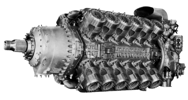
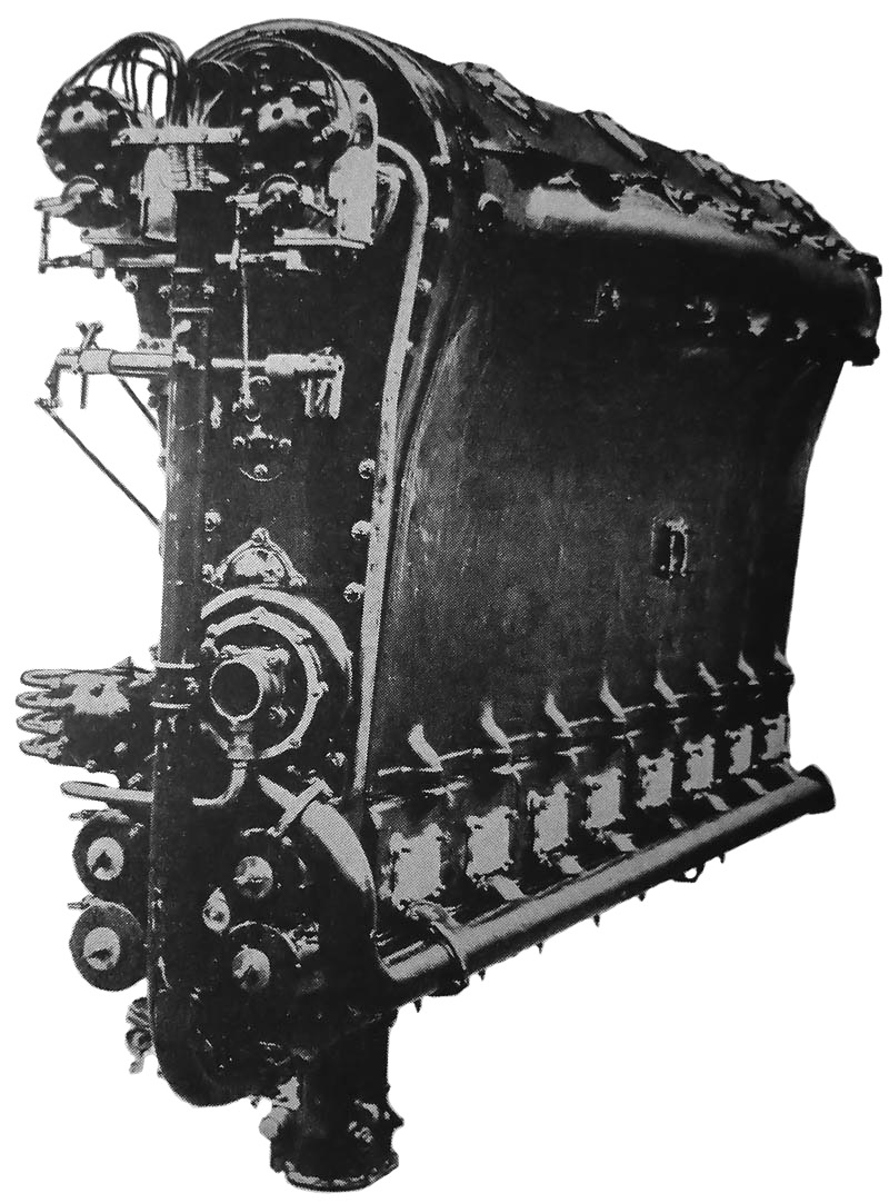
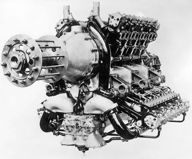
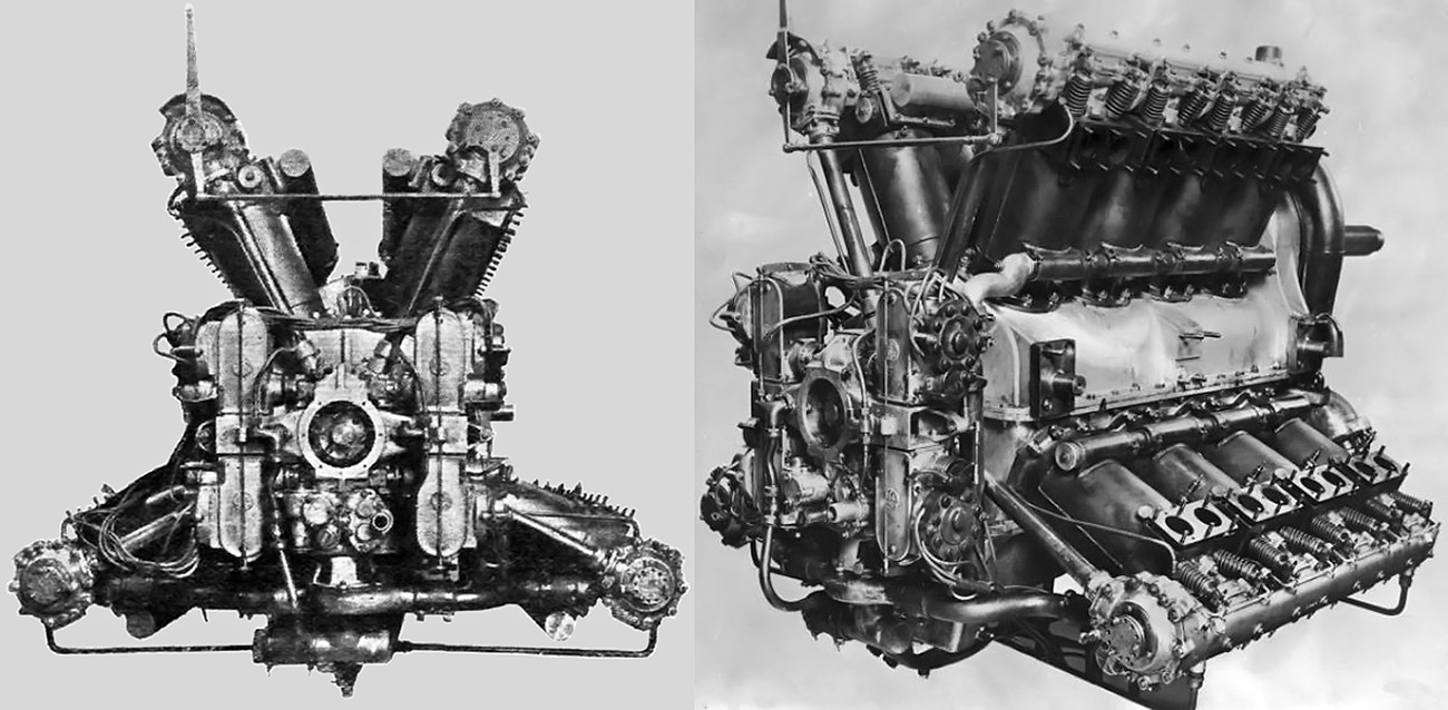
Side view of the J. Paul Miller-developed Duesenberg W-24 engine.
Dodge was very involved in boat racing, and he wanted to create a boat that would be unbeatable. In 1925, Dodge approached Duesenberg Brothers Racing to build an engine to propel him to victory in the Gold Cup race. An agreement was made, and a contact was signed on 27 January 1926—$32,500 for the construction of two complete engines with enough spare parts to build a third. The first engine was to be delivered on 15 June 1926, with the second following on 6 July 1926. Although Fred Duesenberg was involved with the engine project, it was most likely Augie Duesenberg who did the majority of the work.
The contracted engine was essentially three straight-eight engines on a common aluminum crankcase, creating a W-24. Why a “W” engine configuration was chosen is not known, but it does provide for a powerful engine in a fairly compact space. At this same time in history, the Napier Lion W-12 engine was powering record-setting air, land, and marine speed machines, and it is easy to see how the Lion could have served as inspiration.

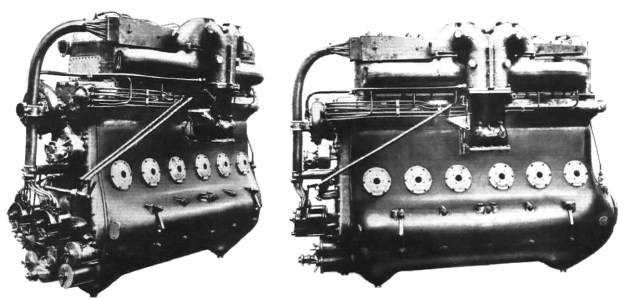
View of the Duesenberg W-24 under construction.
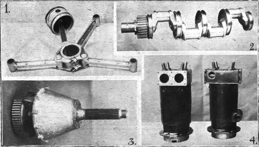
The engine’s bore was 2.875 in (73 mm) and stroke was 4.0 in (102 mm), giving a total displacement of 623 cu in (10.2 L). The two side banks were angled 60 degrees from the center vertical bank. Each of the W-24’s engine banks was made up of two four-cylinder blocks with integral heads. The first four-cylinder blocks were supposedly made of cast iron, but later cylinder blocks were cast aluminum with steel cylinder liners. The engine’s single crankshaft was supported by five main bearings. The connecting rods were of the tubular type, with the master rod in the center bank and an articulated rod for each outer bank.
Four valves per cylinder operated in a pentroof combustion chamber. All together, the engine’s 96 valves took about a week of labor to adjust. The valves were actuated in each engine bank by dual overhead camshafts that extended the length of the engine. The camshafts were geared to the crankshaft via idler gears. Each block of four cylinders had five exhaust ports. The three middle exhaust ports each shared two exhaust valves. Exhaust from each bank was collect in a single water jacketed manifold. One spark plug was installed in each cylinder and fired by a camshaft-driven Delco distributor mounted at the rear of each cylinder bank.

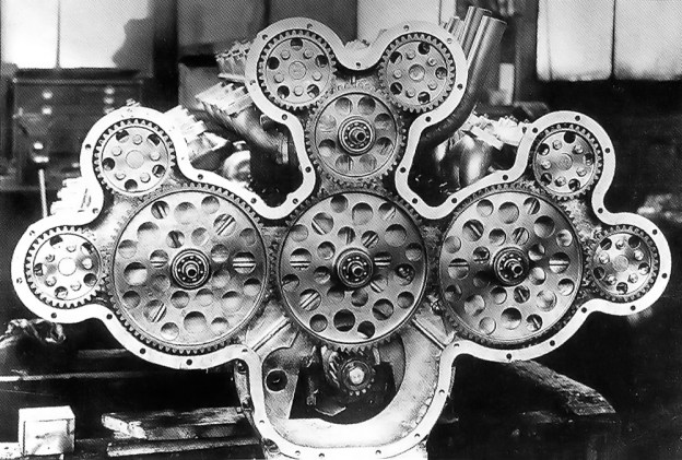
The complex gear-drive arrangement for the camshafts at the rear of the 24-cylinder Duesenberg. The pinion on the crankshaft had 17 teeth, the intermediate gears had 74 teeth, and the camshaft gears had 34 teeth. The center intermediate gear engaged an idler gear that had 45 teeth. The gearing drove the camshafts at half engine speed.
Initially, one updraft carburetor fed air to each of the six four-cylinder blocks. Poor fuel distribution resulted, and the engine never ran well. The updraft carburetors were replaced with downdraft carburetors, and the W-24’s running improved, but it was still not perfect. The six downdraft carburetors were replaced by 12 Zenith downdraft carburetors, improving performance yet again. Finally, 12 Holley downdraft carburetors replaced the Zeniths, and the engine began to run smoothly. Although running better than ever, the W-24 only produced a disappointing 475 hp (354 kW).
The first engine was delivered to Dodge in 1927. Earlier that year, J. Paul Miller began working at the Duesenberg factory and was involved with W-24 engine for many years. Some of Miller’s first changes were installing I-beam connecting rods in place of the tubular ones and replacing the Delco distributors with Bosch magnetos. From 1929 to 1935, Miller worked for Dodge and continued to develop the engine. Unfortunately for Dodge, the 24-cylinder engines brought nothing but frustration. As a result, he never paid Duesenberg the last $2,000 for the engines.

Rear of the 24-cylinder Duesenberg showing two two-barrel carburetors feeding the supercharger. Note the camshaft-driven Bosch magnetos.
The 1931 Gold Cup race was held on Lake Montauk in New York, and the W-24 engine was installed in Dodge’s Miss Syndicate III boat. Miss Syndicate III failed to finish the first heat. In 1932, Miss Syndicate III had been renamed Delphine V. Dodge Sr. had named a yacht after his daughter, and Dodge Jr. continued the “Delphine tradition,” naming numerous boats after his sister. Again, the Gold Cup race was held on Lake Montauk in New York. During the first heat race, the W-24-powered Delphine V dropped out after three laps. Dodge entered five boats for the 1933 Gold Cup race held on the Detroit River. A 24-cylinder Duesenberg was installed in two of the entries: the new Delphine VIII and the new Delphine IX. That year, Delphine VIII failed to start, and Delphine IX did not finish a single heat. In 1934, in disgust, Dodge sold one (but probably both) W-24 engine to Herb Mendelson.
Before the sale, Dodge was inspired by the performance of the supercharged Packard engine in one of this other boats, Delphine IV. Since a rule change allowed superchargers to be used starting in 1935, Dodge had commissioned Miller to design a supercharger for the W-24. This unfinished project was sold to Mendelson, and Miller was retained by Mendelson to continue the work on the engine. It was Miller’s refinements of the supercharged engine that really brought the W-24 to life. The supercharger used an 8 in (203 mm) impeller and spun at 6.5 times crankshaft speed (32,500 rpm at 5,000 rpm engine speed), creating 15 psi (1.03 bar) of boost. Initially, two two-barrel carburetors were used on the supercharged engine, but these were replaced by a single four-barrel Stromberg carburetor. Along with new Miller-designed intake manifolds, the fuel distribution problems were finally solved. The exhaust manifolds were discarded and replaced by 30 vertical exhaust stacks extending into the air. With the changes, the engine weighed 1,400 lb (635 kg) and was referred to as the “Mendelson-Duesenberg W-24.” The engine began to run like a champion and now produced over 850 hp (634 kW) at 5,000 rpm. Reportedly, at full song the engine produced a sound like nothing else on earth.

The W-24 being installed in in the Arena-designed Notre Dame by Gene Arena, Walter Schmid, and Bert MacKenzie.
Mendelson installed the W-24 into his boat, the Clell Perry-designed rear-engined Notre Dame (the first). Its first competition was the 1935 President’s Cup race on the Potomac River. Perry was the driver and won the race. In 1937, Perry was again at the controls when the W-24-powered Notre Dame won the Gold Cup race, held on the Detroit River, averaging 63.68 mph (102.48 km/h) over the 90 mile (145 km) course.
While making a high speed run on the Detroit River in preparation for the 1938 Gold Cup race, Perry was injured when the new Notre Dame (the second) boat went out of control and flipped over. (This accident possibly destroyed one of the W-24 engines.) The new Notre Dame was repaired, and Dan Arena took over the driving duties. He finished second in the President’s Cup race but did not like the boat’s stability. Mendelson asked Arena what he thought was needed to cure the stability issues, and Arena said, “Build another boat.” Mendelson agreed, and Arena designed a new 22 ft (6.7 m) boat, again named Notre Dame (the third), with the W-24 engine placed in front of the driver.

Dan Arena (standing) preparing to run the W-24-powered Notre Dame with his brother Gene as the riding mechanic, as Bert MacKenzie makes final preparations.
After a bit of a rough start, Arena won the 1939 and 1940 President’s Cup races in the new Notre Dame. In 1940 on the Detroit River, the W-24 powered the Notre Dame to a new class speed record of 100.987 mph (162.523 km/h). The boat was placed in storage during World War II but was taken out in 1947 and won the Silver Cup race on the Detroit River and finished second in the President’s Cup race. By this time, competitors were installing WWII surplus Allison engines in their boats, and the Duesenberg W-24 could no longer compete. The engine was removed and placed in storage.
At least one Duesenberg W-24 engine survives along with many spare parts. As of 2013, the engine is owned by Gerard Raney and has been rebuilt for installation in a Notre Dame (the third) replica that is under construction. In the mid-1990s, Miller and Arena were both involved in the project, which is based out of the San Francisco Bay Area. Undoubtedly, the engine and boat combination will be quite a sight when the project is finished.
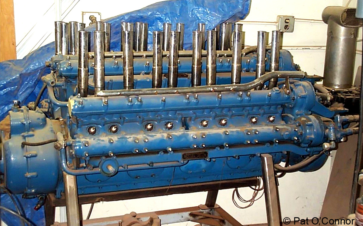
The surviving Duesenberg W-24 engine owned by Gerard Raney as seen in 1996. Note that each cylinder bank is made up of two four-cylinder blocks; the gap between the blocks is visible on the bank nearest the camera. The camshaft housings extend the length of the engine. (Pat O’Connor image)
Sources:
– “The Duesenberg W-24” by Dean Batchelor, Road & Track, August 1992
– “That Kid From Oakland” by Frank Gudaitis, Nautical Quarterly, No. 40, Winter 1987
– “They Always Called Him Augie” by George Moore, Automobile Quarterly, Vol. 30, No. 4 (1992)
– The Classic Twin-Cam Engine by Griffith Borgeson (1979/2002)
– Classic American Runabouts: Wood Boats, 1915-1965 by Ballantyne and Duncan (2005)
– http://www.vintagehydroplanes.com/apba_history/notebook/1996_08.html
– The Dan Arena Story by Fred Farley – ABRA Unlimited Historian
– The Notre Dame Story by Fred Farley – ABRA Unlimited Historian
– 1933 – The Year of the Dodge Navy by Fred Farley – ABRA Unlimited Historian
– http://www.findagrave.com/cgi-bin/fg.cgi?page=sh&GRid=14820517


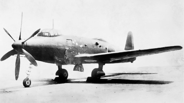
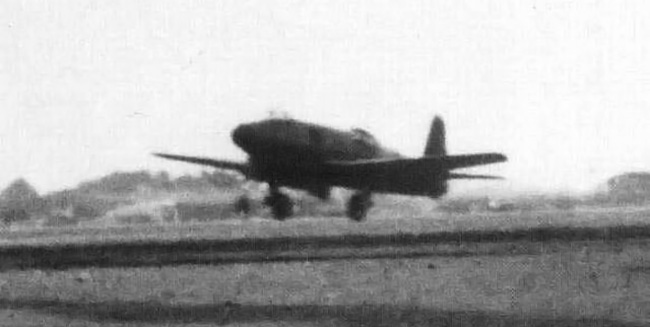
![The standard image of the Yokosuka R2Y1 Keiun. Speculation suggests the first scoop on the side of the aircraft provided cooling air for the engine's internal exhaust baffling, the second, larger scoop provided induction air for the normally aspirated Aichi [Ha-70] engine installed in the prototype, and the final two ports were for the engine's exhaust.](https://oldmachinepress.com/wp-content/uploads/2012/12/yokosuka-r2y1-keiun.jpg)