Author Archives: William Pearce

Rolls-Royce-Vulture

Rolls-Royce Vulture X-24 Aircraft Engine

By William Pearce

In the mid-1930s, the British Air Ministry predicted the need for 2,000 hp (1,491 kW) engines to power new aircraft expected to enter service in the early 1940s. Rolls-Royce responded to this anticipated need with a 24-cylinder, liquid-cooled aircraft engine of an X-configuration, known as the Vulture. Initially, the Vulture design was based on utilizing four six-cylinder banks of the V-12 Kestrel engine. As the Vulture design developed, many changes were incorporated that shifted away from the Kestrel, and the Vulture ultimately had no parts in common with the Kestrel.

Rolls-Royce-Vulture

The Rolls-Royce Vulture X-24 was an attempt to create a 2,000 hp (1,491 kW) aircraft engine. A number of difficulties arose that complicated the engine’s development, leaving history to record the Vulture as a failure.

The Rolls-Royce Vulture was designed by Albert George Elliott, and its development was started in September 1935. The engine’s two-piece aluminum crankcase was split horizontally at the crankshaft’s centerline. Each crankcase half had two surfaces for mounting cylinder banks with an included angle of 90 degrees. The two crankcase halves were attached by 28 cross bolts and a series of smaller bolts along the parting flange. The cross bolts were tightened against the cylinder bank mounting surface and staggered to allow clearance for the cross bolts from the adjoining bank. Each side of the crankcase had two engine mounting pads. The single, hollow, six-throw crankshaft was secured between the two crankcase halves and supported by seven main bearings.

Each of the four monobloc cylinder banks was made of aluminum with an integral cylinder head. Steel liners were inserted for the six cylinders of each bank. Each cylinder bank was secured to the crankcase by 26 long studs that passed through to the top of the bank. The cylinder spacing was wider than that of the Kestrel to accommodate wider connecting rod bearings and to enable a future increase in bore diameter. Each cylinder had two intake valves and two sodium-cooled exhaust valves. The valves for each cylinder bank were actuated by a single overhead camshaft that was driven via bevel gears and by a vertical shaft from the gear reduction at the front of the engine.

Rolls-Royce-Vulture-rear

Rear view of the Vulture shows the coolant pumps flanking the supercharger. All of the cylinder banks were spaced at 90 degrees.

The Vulture’s connecting rod consisted of a master rod extending at a 45-degree angle from a square big end, with three articulating rods extending from the other corners of the big end. Initially, the connecting rod’s big end cap had a hinged joined on one side and was secured to the crankshaft with two bolts on the opposite side. Although different versions were tried, this configuration proved problematic and was replaced by omitting the hinge and using four bolts (two long bolts on one side and two short bolts on the other) to secure the cap to the connecting rod around the crankpin. The mating surfaces of the big end had corresponding serrations to ensure a secure fit. Incidentally, this was the same type of big end employed on the connecting rods of the Rolls-Royce Exe, the development of which had slightly proceeded that of the Vulture. When viewed from the rear of the engine, the upper right cylinder bank was designated as the ‘A’ bank, and the designations proceeded counterclockwise. The master rod served the ‘D’ bank, which was the lower right.

At the front of the engine, a spur gear on the crankshaft engaged four compound layshafts, the opposite side of which drove the propeller shaft. This compound gear reduction resulted in the propeller turning .350 times crankshaft speed and being mounted on the engine’s centerline. Viewed from the rear, the crankshaft and propeller both rotated counterclockwise. A bevel gear on the back side of each compound layshaft drove the vertical shaft for the respective cylinder bank’s camshaft. A spur gear on the rear of the crankshaft supplied power to various accessory drives and to the two-speed, single stage supercharger. The supercharger’s impeller turned at 5.464 and 7.286 times crankshaft speed in low and high gears. A coolant pump was mounted by each side of the supercharger. The engine’s compression ratio was 6.0 to 1.

Rolls-Royce-Vulture-mount

The mounting of the Vulture in the Manchester was similar to other installations—two pads on each side of the engine attached it to a tubular steel frame. The mounting pads were in the Vee formed by the upper and lower banks.

Air was drawn through the two-barrel SU carburetor and fed into the supercharger. The air/fuel mixture exited the supercharger via two outlets that respectively fed an upper or lower manifold. Each manifold was respectively positioned between the upper or lower cylinder banks. The manifold had three outlets on each side. The three outlets were connected to another manifold that was attached directly to and extended the length of the cylinder bank. The incoming charge for each cylinder was ignited by two spark plugs, one positioned in the intake side of the cylinder and the other on the exhaust side. This meant that access to the top, bottom, left, and right sides of the engine was needed to replace the spark plugs. The task was further complicated by the intake manifolds on the top and bottom and the exhaust manifolds and engine mounts on the left and right sides of the engine. Needless to say, the 24-cylinder Vulture was not a favorite with ground crews. The spark plugs were originally fired by a battery-powered coil ignition system, which was replaced by two magnetos and distributors driven from the gear reduction. The exhaust ports were on the left and right sides of the engine. A mixture of 70 percent water and 30 percent ethylene glycol was used to cool the engine.

The Vulture had a 5.00 in (127 mm) bore and a 5.50 in (140 mm) stroke. The engine’s total displacement was 2,591 cu in (42.47 L), and it had a takeoff rating of 1,800 hp (1,342 kW) at 3,200 rpm with 6 psi (.41 bar) of boost. At 3,000 rpm with 6 psi (.41 bar) of boost, the Vulture had a maximum rating of 1,845 hp (1,312 kW) at 5,000 ft (1,524 m) and 1,710 hp (1,223 kW) at 15,000 ft (4,572 m). At 2,850 rpm with 6 psi (.41 bar) of boost, the Vulture had an international rating of 1,780 hp (1,327 kW) at 4,000 ft (1,219 m) and 1,660 hp (1,237 kW) at 13,500 ft (4,115 m) and a maximum climb rating of 1,760 hp (1,312 kW) at 5,000 ft (1,524 m) and 1,640 hp (1,223 kW) at 15,000 ft (4,572 m). At 2,600 rpm with 5 psi (.34 bar) of boost, the engine had a maximum cruise rating of 1,540 hp (1,148 kW) in low gear and 1,460 hp (1,089 kW) in high gear. The Vulture was 87.2 in long, 35.8 in wide, and 42.3 in tall. The engine weighed 2,450 lb.

Rolls-Royce-Vulture-II-IV-Installation-Drawing

Installation Diagram for the Vulture II and IV engines. The main difference between the two variants was that the Vulture II drive an auxiliary gearbox via a right-angle drive mounted vertically behind the ‘A’ cylinder bank.

Preliminary testing of the Vulture engine included building an X-4 engine, and running this engine revealed the issues with the early two-bolt connecting rod design. Stresses on the bolts caused their failure, and the four-bolt connecting rod was developed. Another issue was insufficient lubrication of main bearings. The first complete 24-cylinder Vulture was run on 1 September 1937, the second in January 1938, and the third in May 1938. By November 1938, Vulture test engines had accumulated 1,150 hours of operation. Issues with the coil ignition system came to light while testing the complete engines, resulting in a switch to magnetos. In 1938, the Vulture produced 1,750 hp (1,305 kW) while on test.

Vulture engine development spanned from Mark I to Mark V. The Vulture I entered limited production and were mainly developmental engines. Refinements were incorporated into the Vulture II, which was intended for use in multi-engine aircraft. The Vulture II had a detached, five-drive, auxiliary gearbox that was driven from the engine by a flexible shaft. The flexible shaft connected to a right-angle drive mounted vertically behind the A (upper right when viewed from the rear) cylinder bank. The Vulture II was first run in September 1938. No descriptive information has been found regarding the Vulture III. The Vulture IV was nearly identical to the Vulture II but intended for single-engine aircraft. The Vulture IV had an engine-mounted three-drive auxiliary gearbox and different accessories.

The Air Ministry authorized engine production on 23 March 1939, anticipating a need for 1,560 Vultures, and true engine production started in January 1940. Issues with the Vulture necessitated a drop in its maximum speed to 3,000 rpm, but boost was increased to 9 psi (.62 bar) to maintain the engine’s takeoff rating of 1,800 hp (1,342 kW).

Hawker-Henley-K5115-Rolls-Royce-Vulture-II

The Hawker Henley testbed (K5115) was the first aircraft to fly with a Vulture engine. The large scoop under the aircraft accommodated the coolant radiator and oil cooler.

Development of the Vulture V followed that of the Vulture IV and featured additional supercharging, with an impeller that turned at 6.018 and 8.111 times crankshaft speed in low and high gears. For takeoff, the engine had a rating of 1,995 hp (1,488 kW) at 3,000 rpm with 9 psi (.62 bar) of boost. Military power at the same rpm and boost was 2,035 hp (1,517 kW) at 5,000 ft (1,524 m) and 1,840 hp (1,372 kW) at 20,250 ft (6,172 m). At 2,650 rpm and with 7 psi (.48 bar) of boost, the Vulture V had a cruise rating of 1,650 hp (1,230 kW) at 3,500 ft (1,067 m) and 1,525 hp (1,137 kW) at 17,500 ft (5,334 m).

The Hawker Henley light-bomber prototype (K5115) was converted with a Vulture engine to serve as a testbed. A ventral scoop was added to the aircraft’s bomb bay that housed the radiator and oil cooler. The cowling was modified for the Vulture with its four rows of exhaust stacks, and a scoop for the carburetor was added just forward of the cockpit. The Vulture-powered Henley was first flown on 17 April 1939, and the Vulture passed a type-test with an 1,800 hp (1,342 kW) takeoff rating in August 1939. A second Henley (L3302) was converted to a Vulture testbed and made its first Vulture-powered flight on 3 May 1940. The Vulture engine was intended for a number of aircraft under development, four of which were flown.

The Avro 679 Manchester medium bomber used two Vulture I engines and was ordered in mid-1937, before the aircraft’s design was finalized. Eventually, orders for some 700 examples were placed. The Manchester prototype (L7246) made its first flight on 24 (some sources state 25) July 1939. When Vulture II engines became available, they were used in the Manchester, and the type entered service in November 1940.

Avro-Manchester-Mk-I

A production Avro Manchester I (L7288) running up one of its Vulture engines. A shroud covered each exhaust manifold to help cool the exhaust so that the discharge did not heat the wing. The two-engine bomber was quite a handful when one of the Vultures failed, and a number of aircraft and their crew were lost due to engine issues.

The Vickers Type 284 Warwick medium bomber was originally ordered in October 1935, but a change for the first prototype (K8178) to be powered by two Vulture I engines rather than the Bristol Hercules occurred in January 1937. K8178 made its first flight on 13 August 1939, and Vulture II engines were installed in November 1940.

Two prototypes of the Hawker Tornado fighter were ordered in December 1938. The first prototype (P5219) was powered by a Vulture II engine and made its first flight on 6 October 1939. Production contracts were issued in November 1939, with the Vulture V selected as the intended powerplant. The second prototype (P5224) used a Vulture V engine and made its first flight on 7 December 1940.

The Blackburn B-20 flying boat (V8914) was ordered in 1936 and made its first flight on 26 March 1940. The experimental aircraft was powered by two Vulture II engines and featured an extendable hull and retractable wing floats. The aircraft was lost on 7 April 1940 after aileron flutter was experienced during a high-speed test flight.

In March 1941 the improved Vulture II was type tested with a takeoff rating of 2,010 hp (1,499 kW) at 3,000 rpm with 9 psi (.62 bar) of boost. At the same rpm and boost, the engine’s military power rating was 1,845 hp (1,376 kW) at 5,000 ft (1,524 m) and 1,710 hp (1,275 kW) at 15,000 ft (4,572 m). At 2,850 rpm and with 6 psi (.41 bar) of boost, the Vulture II had a normal rating of 1,780 hp (1,327 kW) at 4,000 ft (1,219 m) and 1,660 hp (1,238 kW) at 13,500 ft (4,115 m). However, the Vultures in service were taking a turn for the worse.

Vickers-Warwick-K8178-Rolls-Royce-Vulture

The Vickers Warwick prototype (K8178) was the only example of the type fitted with Vulture engines.

The Manchester’s rush into production and subsequent rush into service meant that a number of deficiencies with the airframe and serious issues with the Vulture engine were not discovered until it was too late. The engines proved to be unreliable and prone to failure. As a result, all Manchesters were grounded numerous times. Manchesters with a failed Vulture were often unable to maintain height on one engine, and about 75 percent of the time, the aircraft crashed before an emergency landing could be executed at a suitable location. A contributing factor to the Vulture’s issues was that the Battle of Britain forced Rolls-Royce to focus on the Merlin engine, which delayed Vulture development.

Some engine failures were attributed to cooling issues. One of the coolant pumps would cavitate, halting the flow of coolant to that side of the engine. The affected cylinder banks would subsequently overheat, and the engine would seize; an engine fire resulted on a number of occasions. To fix the issue, a balance tube was installed which connected the inlet of the pumps to equalize pressure between the two. The crankshaft main bearings were also prone to failure. Numerous issues resulted in the failed bearings: over-heating due to the already mentioned coolant issues, poor lubrication, ineffective bearing material, and a slight misalignment of the two crankcase halves. The Vulture’s lubrication system was reworked to prevent aeration, and a new LA4-type bearing material was adopted. The misalignment issue was solved by including locating dowels through which cross bolts passed. A dowel was positioned on each side of the main bearings between the crankcase halves. The most vexing issue was the random failure of bolts securing the connecting rod cap. This typically created cascading failures that resulted in the sudden and catastrophic loss of the engine. The issue was traced to brittle bolts, and new measures were implemented to ensure they were tightened to the new, lower toque standard to prevent excessive strain and stretching. The connecting rod was also modified slightly. In addition, the Vulture’s maximum speed was reduced again to 2,850 rpm to minimize the risk of failure. The last of these changes were detailed by Rolls-Royce under Vulture Modification No. 44. By August 1941, engines with these changes were installed in some Manchesters, and the Vulture began to reliably make it 120-hours between major inspections. In addition, Manchesters were now able to make it to an airfield on a single engine more often than not. Eventually, the time between inspections was raised to 180 hours, and the engine’s maximum takeoff speed was increased to 3,000 rpm. However, another issue with Vulture engines came to light in late 1941. Exhaust manifolds were cracking and failing, resulting in a jet of hot gasses flowing against the engine, cowling, or other internal components. The failed manifolds caused engine failures or airframe damage or both. A new manifold was designed, and all of the older units were replaced in December 1941.

Hawker-Tornado-P5224

The second Hawker Tornado prototype (P5224) with its Vulture V engine. The Vulture was relatively well-behaved during testing of the Tornado, which was very similar to the Sabre-powered Typhoon.

Even though the main problems with the Vulture were mostly resolved, engines continued to encounter various random issues, including failures, overheating, lack of power, and excessive fuel consumption. Overall, there was little faith in the Vulture engine. The Manchester itself continued to have issues, and production was halted in November 1941. Of the 202 aircraft built, approximately 33 (16.3 percent) crashed or were struck off charge due to engine failures or fires. This number does not include aircraft that were repaired after an engine failure, nor does it include the six or so aircraft lost due to propeller issues (some of which precipitated an engine failure). Tragically, also not included are the numerous Manchesters that crashed after one engine was knocked out from battle damaged only to have the “good’ engine fail after it was overstressed trying to keep the underpowered aircraft aloft. The Manchester was withdrawn from operations in mid-1942 and served in various secondary roles through 1943, when all examples were scrapped.

The Manchester was redesign to use four Merlin engines and became the Lancaster (originally Manchester III), one of the greatest World War II bombers. Production Warwicks were fitted with either Pratt & Whitney R-2800 or Bristol Centaurus engines. While around 1,760 Tornados were ordered at one point, only three Vulture-powered examples were built, and the Napier Sabre-powered Typhoon took over in place of the Tornado.

Blackburn-B-20

The Blackburn B-20 was an experimental aircraft which tested a retractable hull to improve the aerodynamics of flying boats. With a top speed of over 300 mph (483 km/h), the B-20 showed potential, but it was lost during an early test flight.

By September 1942, a Vulture engine with a contra-rotating gear reduction was installed in the sole-production Tornado (R7936). The engine and aircraft were used to test Rotol and de Havilland contra-rotating propellers. Some sources report that one Vulture engine was built with its bore increased by .4 in (10 mm) to 5.4 in (137 mm), the same as the Merlin. This increased the engine’s displacement by 432 cu in (7.08 L) to 3,023 cu in (49.54 L). However, no further information on these engines has been found.

From as early as August 1939, Rolls-Royce wanted to cancel Vulture development so that the company could focus its resources on other engines, mainly the Merlin and Griffon. However, the Air Ministry felt that it needed the Vulture engine, so development continued. Vulture development was halted in October 1941, and production ended in March 1942, with 538 engines built. The Vulture was the only X-24 aircraft engine to enter production.

Rolls-Royce had designed a number of changes to be incorporated into the Vulture engine if production had continued. The connecting rod was redesigned with the three articulated rods attached to the bearing cap, and the cap was secured to the master connecting rod via four long bolts made from improved material. The cylinder banks were redesigned to incorporate a detachable cylinder head. A lighter planetary gear reduction for the propeller would have replaced the four compound layshafts. The two-speed supercharger was redesigned to include two-stage supercharging to improve the engine’s performance at higher altitudes.

Hawker-Tornado-R7936-DH-cr-props

The sole-production Tornado (R7936) seen in 1943 with a Vulture engine turning de Havilland contra-rotating propellers. The aircraft was also used to test Rotol contra-rotating propellers.

Only a small number of Vulture engines survive, and most were recovered from Manchester wrecks. Two recovered Manchester engines (engine 1 and engine 2) are held by the Luchtoorlogmuseum (Aerial Warfare Museum) Fort Veldhuis in Heemskerk, near Amsterdam in the Netherlands. A Vulture engine from the B-20, consisting mainly of the crankshaft, connecting rods, and cylinder barrels, is displayed in the Dumfries and Galloway Aviation Museum in Scotland. Three engines are part of the Royal Air Force Museum’s collection, and all are believed to have been recovered from Manchester wrecks. One of these engines is on loan to the Rolls-Royce Heritage Trust and is displayed at the Hucknall Flight Test Museum.

Note: Many sources state that the Vulture I used an updraft carburetor, and the Vulture II and later variants used a downdraft carburetor. However, the only aircraft that appears to have had an updraft carburetor was the first Tornado prototype, which reportedly flew with a Vulture II. Early Manchesters that reportedly flew with Vulture Is appear to have downdraft carburetors. In my opinion, the most logical explanation, although still questionable, is that all Vultures had downdraft carburetors and that the early installation in the Tornado prototype that incorporated the carburetor inlet with the belly scoop was an attempt to maximize the pilot’s forward vision and minimize the number of external protuberances.

Rolls-Royce-Vulture-crash

The shattered remains of a Vulture II engine from Manchester R5779 shot down on 9 March 1942 near Oranje, Netherlands. The engine is actually on its side, and the view is of the induction manifold on the bottom of the engine. Note the severe deformation of the cylinder bank. The engine is displayed at the Luchtoorlogmuseum (Aerial Warfare Museum) Fort Veldhuis in Heemskerk. (Fort Veldhuis Airwarmuseum image)

Sources:
Major Piston Engines of World War II by Victor Bingham (1998)
The Avro Manchester: The Legend Behind the Lancaster by Robert Kirby (2015)
Rolls-Royce Piston Aero Engines – a designer remembers RRHT 16 by A. A. Rubbra (1990)
Rolls-Royce Vulture II and IV Description: Air Publication 1801A Volume I, via the Aircraft Engine Historical Society (December 1940)
Rolls-Royce Aero Engines by Bill Gunston (1989)
Aircraft Engines of the World 1945 by Paul H. Wilkinson (1945)
Hawker Aircraft since 1920 by Francis K. Mason (1991)
Avro Aircraft since 1908 by A. J. Jackson (1990)
Vickers Aircraft since 1908 by C. F. Andrews and E. B. Morgan (1988)
Blackburn Aircraft since 1909 by A. J. Jackson (1989)
https://www.key.aero/forum/historic-aviation/62280-rolls-royce-vulture-survivors

Hawker-Tornado-P5224-front

Hawker Tornado Fighter

By William Pearce

In early 1937, Hawker Aircraft Limited and the company’s chief designer, Sydney Camm, began to consider the next generation of fighter aircraft for the Royal Air Force. The British Air Ministry was also considering the future of fighter airframes as well as the incorporation of powerful, new engines under development—specifically the Napier Sabre H-24, the Rolls-Royce Vulture X-24, and the Bristol Centaurus 18-cylinder radial.

Hawker-Tornado-P5219-front

The first Hawker Tornado prototype P5219 in its original form with the belly radiator. The Vulture’s two rows of exhaust stacks are evident. The aircraft’s resemblance to the Hurricane is apparent.

In July 1937, Hawker proposed two Camm-designed aircraft—the N-type and the R-type, named for their respective Napier and Rolls-Royce powerplants. The Air Ministry told Hawker to wait until an official request was issued, which came in March 1938 in the form of Specification F.18/37 seeking a fighter capable of 400 mph (644 km/h) at 20,000 ft (6,096 m). Hawker was notified in August 1938 that they had won the design contest for Specification F.18/37, and two prototypes of each N-type and R-type were ordered. However, an official contract was not issued until December 1938. The N-type went on to become the Sabre-powered Hawker Typhoon, while the R-type became the Vulture-powered Hawker Tornado. The two Tornado prototypes were assigned serial numbers P5219 and P5224.

The Tornado was a single-engine fighter of all-metal construction with a conventional taildragger layout. The aircraft somewhat resembled an enlarged Hawker Hurricane. From the engine to just behind the cockpit, the fuselage consisted of a tubular frame covered with aluminum panels. The rear fuselage and tail were of monocoque construction. The pilot sat in an enclosed cockpit that was accessible via side entry doors. A fairing extended behind the cockpit and limited the pilot’s rearward vision.

The Tornado’s wing was mounted to the tubular frame of the center fuselage. Because of the Vulture’s installation, the wing was mounted to the fuselage about 3 in (76 mm) lower than on the Typhoon. The wing had two main spars and consisted of an inner and outer section. The inner section had a 1.0-degree anhedral and housed the inward-retracting main landing gear. The landing gear had a wide track of 13 ft 8 in (4.17 m). A 48 US gal (40 Imp gal / 182 L) fuel tank was located in each wing between the main gear leg well and the rear spar, and a 42 US gal (35 Imp gal / 159 L) fuel tank was located in the leading edge of each inner wing section. The Tornado’s total fuel capacity was 180 US gal (150 Imp gal / 682 L). Each outer wing section had a 5.5-degree dihedral and housed six Browning .303 machine guns with 500 rpg. The thick wing was originally designed for the possible installation of six 20 mm cannons, but this configuration was never tried. Each wing had a two-section, hydraulically actuated split flap and featured a large aileron. Except for the fabric-covered rudder, all control surfaces were covered with metal.

Hawker-Tornado-P5219-rear

Another shot of the newly completed P5219 displays the aircraft’s original short tail. Note the opaque fairing behind the cockpit that blocked the pilot’s vision.

The Tornado’s Rolls-Royce Vulture II engine had 24 cylinders arranged in an X configuration. The engine was mounted to the forward part of the tubular fuselage frame and produced 1,760 hp (1,312 kW). Two rows of exhaust stacks protruded from each side of the engine’s cowling. A belly scoop between the main gear wells housed the engine’s coolant radiator and oil cooler. A door in the aft section of the scoop regulated temperatures. Two intakes between the belly scoop and the underside of the fuselage fed air to the engine’s carburetor. The engine turned a three-blade, constant-speed Rotol propeller that was 14 ft (4.27 m) in diameter.

The Hawker Tornado had a wingspan of 41 ft 11 in (12.78 m), a length of 32 ft 10 in (10.01 m), and a height of 14 ft 8 in (4.47 m). The aircraft had a top speed of 398 mph (641 km/h) at 23,000 ft (7,010 m) and stalling speeds of 82 mph (132 km/h) clean and 61 mph (98 km/h) with flaps and gear extended. The Tornado had an empty weight of 8,377 lb (3,800 kg) and a loaded weight of 10,668 lb (4,839 kg). The aircraft’s initial rate of climb was around 3,500 fpm (17.8 m/s), and its ceiling was 34,900 ft (10,638 m).

Hawker-Tornado-P5224-front

The second Tornado prototype P5224 with the chin radiator and windows behind the pilot to help improve vision. The aircraft now resembles a Typhoon, with which it shared many components.

The Tornado prototype P5219 was built at the experimental shop in Hawker’s Canbury Park Road facility in Kingston, but it was sent to Hawker’s new facility in Langley for final assembly in July 1939. The Vulture II engine was delivered in September 1939, and ground tests were started later that month. Piloted by Philip Lucas, P5219 made its first flight on 6 October 1939. During the preliminary flight tests in October and November, the aircraft achieved a speed of 370 mph (595 km/h) at 15,000 ft (4,572 m). However, the Tornado’s tail was lacking in surface area, and the rudder did not have sufficient authority to hold a straight course during takeoff and proved ineffective at speeds under 150 mph (241 km/h). Engine cooling was a constant issue, especially during ground operations. While in flight at higher speeds, turbulence from the wings disrupted airflow into the radiator, which impaired engine cooling. A new radiator was designed that would relocate the cooling system from its ventral position to a chin location under the engine. Metal was also found in the engine oil, indicating a possible issue with the Vulture’s bearings.

While the Vulture engine was undergoing maintenance, the Tornado airframe was modified with the new chin radiator and oil cooler, which shifted the aircraft’s appearance away from that of the Hurricane. In November 1939, an order for Hawker to produce 1,000 Tornados was placed. The contract was later changed to Typhoons, but then amended for 800 Typhoons and 200 Tornados, with the Tornados to be built by Avro due to Hawker’s production commitments of other aircraft, namely the Hurricane. Other Tornado production contracts were later issued, including 200 aircraft to be built by Cuncliffe-Owen and another 760 aircraft to be built by Avro. The revised Tornado took to the air on 6 December 1939, but Lucas reported that the aircraft was even more directionally unstable with the chin radiator. Performance tests in March 1940 indicated a top speed of 384 mph (618 km/h) at 20,500 ft (6,248 m), but the engine was not making full power. Various modifications were made to improve the aircraft’s stability. The exit of the radiator was extended 3 in (76 mm); the vertical stabilizer and rudder were enlarged in May 1940; and tailwheel doors were added in June 1940.

Hawker-Tornado-P5224-in-flight

P5224 in flight displaying the aircraft’s aggressive appearance and enlarged tail. Note the carburetor intake atop the engine cowling.

With stability improved, P5219 was sent to Rolls-Royce’s flight-testing facility at Hucknall to improve the engine’s performance. The aircraft was returned to Langley in mid-July 1940 with a new engine and a new Rotol propeller that was 13 ft 2.5 in (4.02 m) in diameter. Performance flight testing continued, and on 27 July, the Tornado climbed to 20,000 ft (6,096 m) in 6 minutes and 36 seconds and achieved a speed of 396.5 mph (638.1 km/h) at 20,800 ft (6,340 m). On 31 July, the Vulture engine failed in flight, and the aircraft was damaged in the subsequent forced landing.

While P5219 was being repaired, the second Tornado prototype, P5224, was flown on 7 December 1940. Construction of the second prototype was delayed by other priority war work. P5224 was built from the start with the chin radiator and an enlarged tail. The aircraft also had the carburetor intake atop the engine cowling, inner gear doors to completely enclose the main gear, and side windows behind the cockpit to improve the pilot’s vision (which was still restricted). However, engine cooling was still an issue, as were excessive vibrations with the Vulture engine.

The repaired P5219 returned to active flight testing with a 1,980 hp (1,476 kW) Vulture V engine installed by March 1941, but the future of the Vulture engine was in doubt. P5224 suffered an engine failure on 21 March 1941, and its Vulture II was subsequently replaced by a Vulture V. P5224 first flew with the Vulture V on 11 June 1941. Around June 1941, Avro was instructed to halt work on producing the Tornado fighter, and the Tornado contracts were cancelled. The Vulture engine was stalled by Rolls-Royce so they could focus on the Merlin, and the Vulture was officially cancelled in October 1941. The Sabre-powered Typhoon fighter would be produced and take over resources previously allocated to the Tornado.

Hawker-Tornado-CR-props

The first and only production Tornado, R7936, was used as a propeller testbed after its initial flight testing. The aircraft is seen here with Rotol contra-rotating propellers, which had a smaller diameter than the standard, single-rotation propellers used on the Tornado and Typhoon. Note that the aircraft did not have the windows behind the pilot like the second prototype.

P5219 continued flight testing with Hawker until at least April 1943, and the aircraft was scrapped in August 1943. P5224 was tested by the Aeroplane & Armament Experimental Establishment at Boscombe Down starting in October 1941. The aircraft was then delivered to the Royal Aircraft Establishment at Farnborough in December 1941. P5224 was scrapped in late 1944.

After the Tornado contracts were cancelled, construction of the first production Tornado, serial number R7936, was allowed to continue as well as components for two other examples that were nearing completion. R7936 was powered by a Vulture V engine and made its first flight on 29 August 1941, piloted by Lucas. In general, pilots that flew R7936 were impressed by its handling and performance. The aircraft recorded a speed of 402 mph (647 km) at 21,800 ft (6,645 m) and climbed to 20,000 ft (6,096 m) in 6 minutes and 54 seconds. With the Tornado program dead, R7936 was used as a testbed for Rotol and de Havilland contra-rotating propellers. Little information has been found on these tests, but the aircraft was delivered to Rolls-Royce in March 1942 for the installation of a Vulture engine with a contra-rotating gear reduction. The six-blade Rotol contra-rotating propeller was 11 ft 3 in (3.43 m) in diameter, and the aircraft was first flown with the unit on 11 August 1942. The de Havilland contra-rotating propellers were installed as early as December 1942. It appears R7936 continued with propeller tests until April 1944, when it was scrapped.

Hawker-Tempest-HG641-side-org

Typhoon HG641 was built to serve as a testbed for the Bristol Centaurus engine. Seen here with its original three-blade propeller, cowling, and single large exhaust manifold. The silhouette of the oil cooler can just be seen between the main landing gear.

From the first discussion with the Air Ministry before Specification F.18/37 was issued, Camm and Hawker had given some consideration to a Centaurus-powered Tornado, but little progress was undertaken beyond the preliminary design. With the Vulture and Sabre engines running into development issues by late 1940, more-serious consideration was given to installing a 2,210 hp (1,678 kW) Centaurus engine in a Tornado airframe. In September 1940, Hawker was given permission to proceed with the Centaurus-powered Tornado prototype, but the official contract was not issued until February 1941. Some work was also done on using a Wright R-3350 engine, but this design was dropped in June 1941.

The Centaurus Tornado was assigned serial number HG641. The aircraft was built by Hawker at Langley using components from uncompleted Tornado production airframes and a new center fuselage. The Centaurus engine turned a 12 ft 9 in (3.89 m) diameter, three-blade, Rotol propeller and was covered by a conventional cowling. Exhaust from the engine was expelled via a single manifold protruding from the cowling under the left side of the engine. An oil cooler was mounted between the wells for the main landing gear. The air-cooled radial reduced the aircraft’s weight by about 350 lb (159 kg). Lucas took the Centaurus Tornado up for its first flight on 23 October 1941.

Hawker-Tempest-HG641-side-mod

HG641 with the new four-blade propeller and revised cowling. The oil cooler was located in the large duct under the engine.

Initial flight tests of HG641 indicated that airflow through the oil cooler was not efficient and led to the engine running near its upper temperature limit. Even so, a speed of 378 mph (608 km/h) was recorded at 20,000 ft (6,096 m). The oil cooler was modified, and testing continued until December 1941. At that time, the aircraft was modified to improve the installation of the engine package, including exhaust and oil cooler. The cowling was revised, and a new oil cooler duct was faired into the lower cowling. Two exhaust stacks were incorporated into the left and right sides of the fairing. A four-blade propeller, also 12 ft 9 in (3.89 m) diameter, was installed, and the modified Centaurus Tornado took its first flight on 23 December 1942, piloted by Lucas. Cooling was improved, and the aircraft achieved 403 mph (649 km/h) at 22,000 ft (6,706 m) and had a ceiling of 32,800 ft (9,997 m). In February 1943, the aircraft was transferred to Bristol’s facility in Filton, where a speed of 412 mph (663 km/h) at 18,000 ft (5,486 m) was reportedly recorded. The Centaurus Tornado continued engine testing until August 1944, when the aircraft was scrapped.

The testing of Tornado aircraft provided information for developing the Typhoon fighter, contra-rotating propellers, and the Bristol Centaurus engine, which was particularly helpful when applied to the Centaurus-powered Hawker Tempest II fighter. Although the Tornado has been mostly forgotten, both the Typhoon and the Tempest served with distinction during World War II.

Hawker-Tempest-HG641-rear-mod

Side view of HG641 with the new cowling. The aircraft did not have the windows behind the pilot and used hinged doors on the landing gear to completely conceal the main wheels. This was also tried on the prototypes before switching to a separate inner door.

Sources:
The Hawker Typhoon and Tempest by Francis K. Mason (1988)
Hawker Typhoon, Tempest and Sea Fury by Kev Darling (2003)
British Experimental Combat Aircraft of World War II by Tony Buttler (2012)
Fighters Volume Two by William Green (1964)
Hawker Typhoon and Tempest: A Formidable Pair by Philip Birtles (2018)
Aircraft of the Fighting Powers Volume V by H. J. Cooper and O. G. Thetford (1944)
The Secret Years: Flight Testing at Boscombe Down 1939 – 1945 by Tim Mason (1998)
Hawker Aircraft since 1920 by Francis K. Mason (1991)

SNCM-130-137-mockup-display

SNCM 130 and 137 24-Cylinder Aircraft Engines

By William Pearce

The history of the SNCM 130 and 137 aircraft engines detailed here has been derived from the research of Sébastien Faurès, which he consolidated into his amazing book, Lorraine-Dietrich.

In mid-1935 the French Service technique de l’aéronautique (STAé / Technical Service of Aeronautics) sought the design of a relatively compact aircraft engine that would produce 600 hp (447 kW) at 13,123 ft (4,000 m), displace around 732 cu in (12 L), and weigh 661 lb (300 kg). The air-cooled engine was intended to power the next generation of light fighter aircraft. Albert Lory was put in charge of the new engine design. Lory had previously worked for Delage automobiles and designed the company’s 15S8 Grand Prix racer that won the Manufacturers’ Championship in 1927. Lory also designed the Delage 12 GVis and 12 CDirs inverted V-12 aircraft engines. Working with the STAé, Lory quickly focused on a 24-cylinder engine of either an X, H, or coupled V-12 configuration.

SNCM-130-137-mockup-display

The SNCM 130 / 137 displayed at the Argenteuil factory in mid-1939. This engine was either a mockup or incomplete, but it was outfitted with the envisioned cowling to make it a complete power package. The radiator would be housed between the ducted spinner and engine. Note the induction scoop positioned above the engine and how the valve train covers form part of the cowling. The holes in the cowling were individual exhaust ports. (image Sébastien Faurès/Lorraine-Dietrich)

Throughout 1936, the STAé engine concept changed quite radically, as did Lory’s design. By late 1937, the liquid-cooled engine was made up of four V-6 engine sections joined by a common crankcase and driving a common crankshaft. Each section would produce 600 hp (447 kW), creating a complete engine capable of 2,400 hp (1,790 kW). Few established engine manufacturers were interested in taking on such an unconventional engine, especially one designed outside of their company. On 31 March 1937, France had nationalized the Société des moteurs et automobiles Lorraine (Lorraine Motor and Automobile Company) and created the state-run Société nationale de construction de moteurs (SNCM / National Society of Engine Construction) in its place, with Claude Bonnier as SNCM’s Managing Director and General Manager. In October 1937, the STAé tasked SNCM to develop the new engine.

The 2,400 hp (1,790 kW) engine design was seen as a little too ambitious, and another redesign occurred. The proposed liquid-cooled, 24-cylinder engine was now formed from three V-8 engine sections on a common crankcase. With six banks of four inline cylinders spaced radially around the crankcase, this engine configuration is often called an inline radial. In addition, the outer points of the six banks formed a hexagon, which qualifies the powerplant as part of the family of rare hexagonal engines. Other hexagonal engines include the Curtiss H-1640 Chieftain, the Wright H-2120, the Junkers Jumo 222, and the Dobrynin series of aircraft engines.

The SNCM engine had an ultimate goal of 1,800 hp (1,342 kW), but it would initially be configured to produce 1,600 hp (1,193 kW). Once this power was obtained, the cylinder’s bore would be increased to achieve an output of 1,800 hp (1,342 kW). The 1,800 hp (1,342 kW) engine was designated SNCM 130. The 1,600 hp (1,193 kW) prototype version, with a reduced bore, was designated SNCM 137 and would be built first. Due to the similarity between the engines and their rather confusing genesis, the SNCM 137 engine is often referred to as the SNCM 130.

SNCM-130-137-patent-drawings

Left, French patent 870,367 drawing showing the four Vee engine sections and the valve train for each cylinder bank pair. Note that the induction was illustrated under the camshaft, which was not the case on the engine as built. Right, French patent 870,359 drawings showing two views of the engine’s combustion chamber. Ports e1 and e2 opposite of the inclined valves were for the spark plugs. Port f was for the fuel injector.

The SNCM 137 had a cast aluminum crankcase made of two-pieces and split horizontally (more like diagonally). The two crankcase halves joined around the four-throw crankshaft, which was supported via five main bearings. A connecting rod consisting of one master rod and five articulating rods was mounted to each of the crankshaft’s throws. Six cylinder banks were mounted at 60-degree intervals around the crankcase. Each cylinder bank consisted of a four-cylinder cast aluminum block with forged steel liners and a detachable cast aluminum cylinder head. The cylinder banks were paired together, forming three groups of eight cylinders. Mounted between each cylinder bank pair was an overhead camshaft that was driven by the crankshaft via a series of gears at the back of the engine. In this configuration, one camshaft served two cylinder banks, and the engine had three camshafts. Each of the two upper camshafts drove a fuel distribution pump from their rear. The single lower camshaft drove an oil pump from its rear and a water coolant pump from its front.

Via rockers, the camshaft actuated the single intake valve and single exhaust valve for each cylinder. The valve train between each cylinder pair was concealed by a large, arched valve cover. The valve cover between the lower cylinder banks extended deeper, past the cylinder heads to act as an oil sump. The valves were inclined in the cylinder head, which had a wedge-shaped combustion chamber. On the side of each cylinder opposite from the valves were two spark plugs and a single fuel injector. The spark plugs were fired by two magnetos driven from the rear of the engine. The engine’s compression ratio was 7 to 1.

A centrifugal single-stage, single-speed supercharger made by Szydlowski-Planiol was located at the rear of the engine, and it provided 3.7 psi (.25 bar) of boost. Air entered the rear of the supercharger, was compressed, and was distributed to each cylinder bank via six separate runners. Each runner was connected to an intake manifold that was cast integral with the cylinder bank. The intake manifolds ran along the outer side of the cylinder bank pairs, although a patent drawing shows the intake located under the camshaft between the cylinder pairs. Exhaust was expelled from a port above each cylinder. An engine mount extended between the intake manifolds in the open Vee between the cylinder banks.

SNCM-130-137-construction

Two images of the SNCM 130 / 137 under construction at the former Lorraine factory. On the left, the valve train is apparent between each cylinder bank pair. Note the diagonal split on the end of the crankcase, which illustrates the crankcase’s two halves. On the right is the rear of the completed engine with its supercharger and intake runners. Note the arched valve train covers. (image Sébastien Faurès/Lorraine-Dietrich)

Mounted to the front of the engine was a propeller gear reduction. Different reductions were available between .333 and .667 crankshaft speed. The gear reduction housing was elongated, and an annular radiator was intended to encircle the housing. A shroud enclosed the radiator, and the propeller’s spinner incorporated a duct to deliver air to the radiator. Three blades in the duct acted as a cooling fan to aid the flow of air through the radiator while the aircraft was on the ground. After flowing through the radiator, the air exited via cowl flaps positioned just before the cylinder banks. As designed, the engine and radiator came fully cowled and represented a power package ready for installation. The gear train covers doubled as part of the engine cowling, with removable panels covering the rest of the engine.

The SNCM 137 had a 5.31 in (135 mm) bore and a 5.12 in (130 mm) stroke. The engine’s total displacement was 2,725 cu in (44.66 L). The SNCM 137 was 46 in (1.18 m) in diameter and was 75 in (1.90 m) long. While Lory continued to lead the project and oversee the engine’s construction, former Lorraine engineer Charles Salusse was also involved with the SNCM 137’s design. Salusse was awarded French patents 870,359 for the combustion chamber design and 870,367 for the Vee-type configurations. Both patents were submitted in November 1940, after Lory had left SNCM following the German occupation, and awarded on 12 December 1941. The second patent illustrates the valve train for the paired cylinder banks and shows the intake positioned under the camshaft. One of the example engines has four Vee-section pairs (eight banks), as considered in an earlier STAé design.

The SNCM 137 was constructed at the former Lorraine plant in Argenteuil, near Paris, France. A mockup, or a partially completed engine, was displayed at the Argenteuil plant in mid-1939. The prototype SNCM 137 was completed by early 1940, and tests were quickly started. By the end of March 1940, 2,000 hours had been completed on a valve test rig, 500 hours of single-cylinder testing had been completed, and the SNCM 137 prototype engine had run for 80 hours. The SNCM 137 had achieved 1,638 hp (1,221 kW) at 3,000 rpm at a simulated altitude of 9,843 ft (3,000 m). However, all further development was stopped with the German invasion on 10 May 1940. Most likely, only the single SNCM 137 prototype engine was built. The SNCM 137 engine was captured by German forces and taken to Germany. The final disposition of the engine has not been found, and no parts of the engine are known to exist.

The SNCM 130 would have been the main production version of the engine, but it was not built. The engine had the same architecture as the SNCM 137, but its bore was enlarged .20 in (5 mm) to 5.51 in (140 mm). This gave the SNCM 130 a total displacement of 2,931 cu in (48.03 L), and its anticipated output was 1,800 hp (1,342 kW) at 3,200 rpm. It was expected to maintain this power to 18,045 ft (5,500 m). Most likely, the small increase in displacement would not alter the engine’s diameter or length from that of the SNCM 137. The SNCM 130 had a forecasted weight of 2,094 lb (950 kg). Some sources refer to the SNCM 130 as the 24E Taurus, with ‘24’ representing the number of cylinders, and ‘E’ standing for étoile, meaning ‘star,’ which is often a foreign term used to describe a radial engine.

SNCM-130-137-test-run

The SNCM 130 / 137 undergoing tests in early 1940. Note the exhaust stacks protruding directly above each cylinder bank and the robust, three-point engine mount. The water pump is visible, attached to the front of the lower camshaft. (image Sébastien Faurès/Lorraine-Dietrich)

Sources:
Lorraine-Dietrich by Sébastien Faurès Fustel de Coulanges (2017)
– “La S.N.C.M. construit un moteur de 1600 cv,” Les Ailes (6 July 1939)
Les Moteurs a Pistons Aeronautiques Francais Tome I by Alfred Bodemer and Robert Laugier (1987)

Beardmore-Inflexible-nose

Beardmore Inflexible / Rohrbach Ro VI Transport

By William Pearce

In 1914, Adolf Karl Rohrbach started working for Luftschiffbau Zeppelin GmbH as the company began to diversify from airship construction into building heavier-than-air aircraft. Claude Dornier was also employed by Zeppelin and was tasked with designing airframes out of metal, rather than wood. Rohrbach worked with Dornier on the design of several aircraft before Rohrbach was reassigned in 1917 to the Zeppelin plant in Staaken, near Berlin, Germany. At Staaken, Rohrbach worked with Alexander Baumann and was involved in the design of large R-Plane (Riesenflugzeuge, or giant aircraft) bombers.

Beardmore-Inflexible-rear

The duralumin fuselage skin of the Beardmore Inflexible exhibited significant wrinkling. The staining above the wings was caused by engine exhaust and oil. Note the cable running from the wing to the lower fuselage.

Immediately following World War I, Rohrbach designed the Zeppelin-Staaken E.4/20. Like Dornier and Hugo Junkers, Rohrbach was pioneering the construction of aircraft using metal and stressed skin. The E.4/20 was an all-metal, four-engine airliner that made its first flight on 30 September 1920. However, the Treaty of Versailles prevented Germany’s possession of large aircraft, and the E.4/20 was scrapped in 1922. That same year, Rohrbach founded Rohrbach Metall-Flugzeugbau GmbH (Rohrbach Metal Aircraft, Ltd) in Berlin. To work around the Treaty of Versailles, aircraft designed at Rohrbach in Berlin were built at an assembly plant in Copenhagen, Denmark or licensed to be constructed elsewhere.

Following World War I, the British Air Ministry became increasingly interested in all-metal aircraft. In 1923, the Air Ministry issued specification No. 18/23 for a large, all-metal, experimental transport, and order No. 445337/23 was awarded to William Beardmore & Company, Ltd in Dalmuir, Scotland for the construction of such an aircraft. At the time, Beardmore was involved in building ships, locomotives, aircraft engines, and airships. In addition, the company had built aircraft under license during World War I. Beardmore was to collaborate with Rohrbach on the design of the transport aircraft. Beardmore outlined the aircraft’s basic specifications, Rohrbach supplied some of the detailed drawings, and Beardmore built the transport. The aircraft was known as the Beardmore AV 1 Inflexible, or the Rohrbach Ro VI, or the BeRo 1—a combination of Beardmore and Rohrbach. Most commonly, the aircraft is referred to as the Beardmore Inflexible. It was not until 1924 that Beardmore obtained the license from Rohrbach and construction of the aircraft began.

Beardmore-Inflexible-top

The Inflexible at Martlesham Heath. In the lower right of the image are the wheel trollies used to move the aircraft sideways into the hangar.

At Beardmore, the design of the Inflexible was initially laid out and modified by William. S. Shackleton. The project was later taken over by Rollo A. de Haga Haig. The aircraft’s design was tested in the Royal Aircraft Establishment’s wind tunnel at Farnborough. Except for its size, the aircraft possessed a fairly conventional layout. The monoplane trimotor had shoulder-mounted wings and taildragger landing gear. One engine was mounted in the nose, and an engine was mounted on each wing. Each engine was a water-cooled Rolls-Royce Condor II that produced 650 hp (485 kW) and turned a wooden, fixed-pitch, two-blade propeller. The radiator for the nose-mounted engine was directly below the fuselage, and the radiator for each wing-mounted engine was located under the wing between the engine nacelle and the fuselage. The two-place, side-by-side, open cockpit was positioned just forward of where the wings mounted to the fuselage. Below the cockpit on the left side of the fuselage was a small propeller for a wind-driven pump. The pump supplied oil to a servo system that boosted movement of the ailerons and elevator.

Beardmore-Inflexible-nose

The group posing in front of the Inflexible gives scale to the aircraft’s immense size. The radiator for the fuselage-mounted engine can be seen under the nose. Exhaust manifolds carried the gasses from the center engine away from the cockpit. Just under the cockpit is the windmill for the servo system pump.

The Inflexible was made of duralumin, an aluminum alloy that incorporates copper, manganese, and magnesium for increased strength. The fuselage had a rectangular cross section and consisted of front and rear sections that were bolted together. Both sections were made of duralumin sheets riveted to a duralumin frame. Mounted to the rear of the fuselage were the horizontal and vertical stabilizers. The elevator spanned the entire length of the horizontal stabilizer. A Flettner servo tab trailed behind the rudder and controlled its movement.

The wings were formed by a wing box that bolted to the fuselage and made up the center wing section. An outer wing section bolted to each side of the wing box and was supported by two spars. Like the fuselage, the wing was covered with sheets of duralumin. A cable that kept each wing in tension while in flight connected the rear spar, at about two-thirds the span of the wing, to the lower fuselage. This cable was tensioned to about 3,000 lb (1,361 kg). The wings had a six-degree dihedral. Sections of the leading and trailing edges of the wings were hinged for access and inspection of the inner wing. The aircraft’s 656 US gal (546 Imp gal / 2,482 L) of fuel was carried in four wing tanks. The Inflexible did not have any flaps, but its large ailerons spanned the outer half of each wing’s trailing edge. Extending from each of the aircraft’s control surfaces was an aerodynamic balance horn.

The Inflexible was on hand at the Royal Air Force Display at Hendon in late June 1928. The aircraft now has “9” painted on the fuselage. In a size comparison, the Inflexible was displayed with a de Havilland DH.71 Tiger Moth (far left). The Tiger Moth’s 22 ft 6 in (6.59 m) wingspan was about one-eighth that of the Inflexible.

The aircraft’s immense weight was supported by two large main wheels and a steerable tailwheel. During component testing, wire wheels collapsed under the expected weight of the Inflexible. New wheels were designed and made from steel and aluminum. Mounted to the wheels were 90-in (2.29-m) tall tires, specially developed by the Dunlop Rubber Company. The weight of the large tires increased by 70 lb (32 kg) when they were filled with air. Each main wheel was supported by a shock-absorbing strut that extended from just inside the engine nacelle. An A-frame mounted to the lower fuselage secured each main wheel. The main gear had a track of 25 ft 7 in (7.80 m). For landing, the main wheels had a hydraulic braking system that could be automatically applied when the tailwheel connected with the ground. This system was designed by Rohrbach engineer Kurt Tank.

The Beardmore Inflexible had a wingspan of 157 ft 6 in (48.01 m), a length of 75 ft 6 in (23.01 m), and a height of 21 ft 2 in (6.45 m). The aircraft had a top speed of 110 mph (177 km/h) at sea level and 101 mph (163 km/h) at 6,500 ft (1,981 m). Its landing speed was 65 mph (105 km/h). The Inflexible had a climb rate of 359 fpm (1.8 m/s) and took 18 minutes and 06 seconds to reach 6,500 ft (1,981 m). The aircraft’s service ceiling was 9,350 ft (2,850 m). The Inflexible had an empty weight of 24,923 lb (11,305 kg), a gross weight of 31,400 lb (14,243 kg), and a maximum weight of 37,000 lb (16,783 kg). Reportedly, the aircraft could seat 20 passengers, but it does not appear that such accommodations were ever installed.

Beardmore-Inflexible-bottom

Underside of the Inflexible as it overflies the Royal Air Force Display at Hendon. The radiators for the wing-mounted engines are visible by the fuselage. Note the aerodynamic balance horns extending from all of the control surfaces.

Construction of the Inflexible progressed slowly and was often delayed by various material shortages. The aircraft was initially given civil registration G-EBNG on 29 December 1925. This registration was cancelled on 12 July 1927, and military serial number J7557 was assigned. The aircraft was completed at Dalmuir, near Glasgow, Scotland, in mid-1927. It was then broken down into various sections and transported by sea from Glasgow to Ipswich, England. However, the Aeroplane and Armament Experimental Establishment had no way to transport the large components from the Ipswich docks to the nearby Martlesham Heath Airfield. Disassembled, the two fuselage sections were 41 ft (12.50 m) long, and the outer wing sections were 61 ft (18.59 m) long. Moving the large sections of the Inflexible to Martlesham Heath required the construction of a special transport with steerable axles. Once assembled, the Inflexible’s wingspan was larger than any hanger opening at Martlesham Heath. Special trollies were built that supported each of the aircraft’s wheels and enabled movement in all directions. With the trollies, the aircraft could be moved sideways into the hanger.

Initial ground tests were started in January 1928, and the Inflexible was soon ready for flight tests when the weather was clear. The aircraft’s first flight occurred on 5 March 1928 and was flown by Jack Noakes. A Beardmore mechanic was also on the flight. The Inflexible took off in about 1,014 ft (309 m) and flew for 15 minutes; at the time, it was the world’s largest aircraft to fly. The Inflexible was stable in flight and exhibited good controls. Further flight testing revealed the aircraft to be underpowered, and its pitch and roll control was lacking in rough weather and at slow speeds. Wake turbulence from the fuselage-mounted engine also caused vibration issues with the aircraft’s tail.

Beardmore-Inflexible-flight

The Inflexible makes a pass during the Royal Air Force Display. The pilot, Jack Noakes, is just visible in the open cockpit.

The Inflexible was displayed for the public on at least three different occasions. On 27–30 June 1928, the aircraft was flown during the Royal Air Force Display at Hendon, near London. On 18–20 May 1929, it appeared at the Norwich Aero Club Air Display at the Mousehold Aerodrome. On 10 June 1929, the Inflexible was at the Cambridge Aero Club Display in Conington.

Beardmore struggled financially after World War I, and the aircraft department closed in February 1929. Rohrbach also suffered financial difficulties, and the company merged with a Deschimag subsidiary to form Weser Flugzeugbau GmbH in 1934. Although the Inflexible had demonstrated the feasibility of all-metal, stressed-skin construction, it would be a few years before the technique was fully adopted by the British aircraft industry. In January 1930, the Inflexible was disassembled for static tests at Martlesham Heath. The aircraft had accumulated 47 hours and 55 minutes of flight time. The engines were removed and placed into storage. After the static tests, the wings, fuselage, and other components were left exposed to the elements for corrosion tests. Occasionally, parts of the duralumin skin were removed and repurposed, and the fuselage served as a space for guards to get out of the weather. The remains of the Inflexible were eventually scrapped in 1931. The only surviving component of the aircraft is one main wheel, which is on display in the Science Museum, London.

Beardmore-Inflexible-side

Aerodynamic wheel covers were added to the aircraft sometime in early 1929. The Flettner tab controlling the rudder extended some distance behind the aircraft. The aerodynamic balance horns of the rudder and aileron are clearly visible.

Sources:
Beardmore Aviation 1913-1930 by Charles Mac Kay (2012)
British Prototype Aircraft by Ray Sturtivant (1990)
Jane’s All the World’s Aircraft 1928 by C. G. Grey and Leonard Bridgman (1928)
British Flight Testing: Martlesham Heath 1920-1939 by Tim Mason (1993)
– “Die Monster von Beardmore” by Philip Jarrett, Flugzeug Classic (May 2002)
https://earlyflightera.com/dr-adolf-rohrbach-chronicles-2/
https://en.wikipedia.org/wiki/Beardmore_Inflexible
https://en.wikipedia.org/wiki/Rohrbach_Metall-Flugzeugbau

Alfa-Romeo-1101-supercharger-rear

Alfa Romeo 1101 28-Cylinder Aircraft Engine

By William Pearce

In the early 1930s, Alfa Romeo began to build aircraft engines based on foreign designs that it licensed for production. By 1938, Alfa Romeo had obtained licenses to produce the Armstrong Siddeley Lynx, Bristol Jupiter and Pegasus, De Havilland Gypsy Major and Gypsy Six, and Walter Sagitta inverted V-12. The company had also used its knowledge and experience with licensed production to design its own engines. However, Alfa Romeo’s own D-series radial engines of the early 1930s were not successful, and its 135 engine, an 18-cylinder air-cooled radial first run in 1938, suffered from reliability issues. Giustino Cattaneo had designed the 135, but he left Alfa Romeo in 1936, before the first engine was built. Still, the design of these original Alfa Romeo engines owed much to the foreign engines built under license.

Alfa-Romeo-1101-supercharger-rear

The Alfa Romeo 1101 28-cylinder engine with its remote, two-speed supercharger. Note the induction system from the supercharger to the cylinders. The fuel injection pump and magnetos can be seen on the back of the engine. One cylinder bank has a seemingly restrictive exhaust manifold attached.

In 1938, Ugo Gobbato, Managing Director of Alfa Romeo, tasked the Special Studies Service (Servizio Studi Speciali / SSS) to design an entirely new aircraft engine. The SSS was Alfa Romeo’s secret or special projects department. Wifredo Ricart, a Spaniard who escaped his country’s civil war and fled to Italy in 1936, was in charge of the new engine’s design, which was designated 281.

The 281 was an inline radial that consisted of seven cylinder banks, each with four cylinders. The liquid-cooled engine was equipped with a single-speed, single-stage centrifugal supercharger. The 281 engine had a 4.72 in (120 mm) bore, a 4.33 in (110 mm) stroke, and displaced 2,126 cu in (34.83 L). With the bore larger than the stroke, the oversquare engine was designed have a relatively small diameter and operate at higher rpm. The engine had an estimated output of 1,480 hp (1,089 kW) at 3,000 rpm. The 281 was designed with then-current power requirements in mind, but did not consider future demands for power increases. The 281 design produced basically the same power as the 135, although it was 35 in (.88 m) in diameter compared to 55 in (1.40 m) for the 135. Realizing that a more powerful engine was needed, Ettore Pagani, also of the SSS, completed a design study in 1939 of an enlarged 281 to produce an excess of 2,000 hp (1,471 kW). This engine became known as the 1101. The 281 was never built.

The Alfa Romeo 1101 was initially designated 101, but it was also referred to as the 1.101 and 1.1.01. However, 1101 has become the most common designation. The design team for the 1101 consisted of Ricart, Orazio Satta, and Giuseppe Busso. The engine had a cast aluminum crankcase with seven cylinder banks mounted radially around its center and spaced at 51.4 degrees. The upper cylinder bank extended vertically from the crankcase. Each cylinder bank contained four cylinders and was made from cast aluminum with an integral cylinder head. Wet cylinder liners made of nitrided steel were installed in the cylinder block. Each cylinder had one intake valve and one sodium-cooled exhaust valve. The intake valve was 2.56 in (65 mm) in diameter, and the exhaust valve was 2.20 in (56 mm) in diameter. The valves for each cylinder bank were actuated via hydraulic tappets by a single overhead camshaft. The camshaft was driven by bevel gears and a vertical shaft from the front of the engine. The one-piece crankshaft was supported by five main bearings. The pistons for each row of cylinders were served by a master connecting rod with six articulated connecting rods. The cylinders had a compression ratio of 6.5 to 1.

Alfa-Romeo-1101-front

Front view of the 1101 illustrates the vertical drives for the camshafts. The four mounts on the front of the gear reduction are visible. A sump is positioned between the two lower cylinder banks.

Mounted to the front of the engine was a propeller gear reduction. Via planetary bevel gears, the propeller shaft rotated at .400 times crankshaft speed. Mounted to the rear of the engine were two fuel injection pumps and two magnetos. The primary injection pump had a maximum flow of 423 gallons (1,600 L) per hour and delivered fuel to the injectors mounted in the intake side of the cylinder head. The secondary fuel injection pump had a maximum flow of 132 gallons (500 L) per hour and delivered methanol (methyl alcohol) to injectors located in the intake manifold just before the intake port of each cylinder. The methanol was used to increase maximum power and reduce detonation. Each of the two magnetos fired one of the two spark plugs mounted in each cylinder.

A shaft extending from the rear of the engine powered a remote, two-speed, centrifugal supercharger. The 1101 engine as built did not have a supercharger mounted in a housing that attached directly to the rear of the crankcase. Some sources indicate that the engine had a two-stage supercharger, but photos show just the remote supercharger with no other stage apparent. Two-stage supercharging was certainly planned for future versions of the 1101 engine. Air entered the back of the supercharger, where it was compressed to provide 11.4 psi (.78 bar) of boost. A duct extending from the supercharger was intended to incorporate an aftercooler, but surviving photos do not show one installed. From the duct, the air entered a semi-annular manifold located at the rear of the engine. Seven individual runners extended from the semi-annular manifold and connected to each cylinder bank. The runners had four outlets grouped in two pairs of two and mounted to the left side of the cylinder bank. Each cylinder bank had four exhaust ports on its right side, and the exhaust ports for the middle two cylinders of each bank were grouped together.

A centrifugal water pump, most likely mounted to the lower rear of the engine, flowed coolant at 14,530 gallons (55,000 L) per hour. The coolant was a mix of 70 percent water and 30 percent ethylene glycol. Double dynafocal engine mounts were located on the back side of each cylinder bank. The propeller gear reduction housing also had four mounts.

The engine was officially designated Alfa Romeo 1101 RC37/87. The “RC” stood for Riduttore de giri (gear reduction) and Compressore (supercharged), and 37/87 designated the critical altitudes (in hectometers) at which maximum continuous power was obtained with its two-speed supercharger. The engine had a 5.31 in (135 mm) bore and a 4.92 in (125 mm) stroke. This gave the 1101 a displacement of 3,057 cu in (50.10 L). However, since the strokes of the articulated rods were slightly longer than that of the master rod, the engine had an actual displacement of 3,066 cu in (50.25 L). Takeoff power was 2,200 hp (1,618 kW) at 2,625 rpm. For one minute at emergency power and 2,800 rpm, the engine produced 2,300 hp (1,692 kW) at 7,546 ft (2,300 m) in low gear and 2,150 hp (1,581 kW) at 26,247 ft (8,000 m) in high gear. For five minutes at military power and 2,700 rpm, the engine produced 2,000 hp (1,471 kW) at 10,827 ft (3,300 m) in low gear and 1,900 hp (1,398 kW) at 28,215 ft (8,600 m) in high gear. Maximum continuous power was achieved at 2,625 rpm, with the engine producing 1,850 hp (1,361 kW) at 12,139 ft (3,700 m) in low gear and 1,750 hp (1,287 kW) at 28,543 ft (8,700 m) in high gear. The 1101 had a diameter of 44.7 in (1.14 m) and was 97.2 in (2.47 m) long. The engine weighed 2,535 lb (1,150 kg) without accessories.

Alfa-Romeo-1101-supercharger-side

The 1101’s aftercooler was to be incorporated into the induction pipe between the supercharger and the ring manifold. Note the shaft housing extending back from the engine to power the supercharger.

The 1101 was designed and built at Alfa Romeo’s plant in Pomigliano d’Arco, near Naples, Italy. As the 1101 was being built, Italy had secured licenses from Germany to build the Daimler-Benz DB 601 and DB 605 engines and tasked Alfa Romeo with their production. This led to the formation in 1941 of Alfa Romeo Avio, a division focused solely on producing aircraft engines. The 1101 engine was completed in late December 1941 and first run in early January 1942. Under tests, the 1101 experienced detonation issues that damaged the pistons and cylinder heads. These issues were caused by the 87 octane fuel and the timing of the fuel injection system.

Development of the engine progressed until early 1943, when the war situation required the dispersal of factories away from populated areas. The 1101 engine project was moved to Armeno in northern Italy, near the Swiss border. The move caused delays, but the entire project was suspended on 8 September 1943, following news of the Italian armistice. The Armeno plant housing the 1101 fell in the territory controlled by the newly formed Italian Social Republic (Repubblica Sociale Italiana), which was mostly controlled by Germany. It is not clear if work on the 1101 engine was resumed or stayed suspended, but by mid-1943, the Armeno plant housed nearly all of the engine’s documentation, the prototype engines, and parts for approximately 20 pre-production examples. On 18 June 1944, all of the materiel in the Armento plant was destroyed by Italian partisans (resistance fighters) to prevent its use by the German military.

Future development of the 1101 included two-stage supercharging to increase the engine’s military power rating to 2,300 hp (1,692 kW). Most likely, this configuration would include an additional centrifugal supercharger incorporated in a housing mounted directly to the rear of the crankcase and mechanically driven from the crankshaft. Investigations were also conducted into turbocompounding the engine. The turbocompounded 1101 would utilize five turbines. Three turbines would be positioned at the front of the engine to recover power from the exhaust and feed it back to the propeller shaft. The remaining two turbines were turbosuperchargers (first stage of supercharging) positioned at the rear of the engine to feed air into the engine’s centrifugal supercharger (second stage of supercharging). The turbocompounded engine was expected to weight 20 percent more, increase fuel efficiency by 15 percent, and produce 2,600 (1,912 kW) hp. However, no such engines were built.

Alfa-Romeo-1101-test-side

The 1101 mounted on what appears to be a test bed. This image gives a good view to the spacing of the intake and exhaust ports. Note the two dynafocal mounts on the back of each cylinder bank. It is not clear if the remote supercharger has been omitted or is just obscured by the mounting frame.

Other developments included enlarging the engine’s cylinder, possibly with a 5.71 in (145 mm) bore and a 5.12 in (130 mm) stroke, so that total displacement was 3,668 cu in (60.1 L). Studies were also undertaken to create a 42-cylinder engine by having six cylinders per bank. Some sources indicate that this engine had a displacement of approximately 4,270 cu in (70 L). However, the bore and stroke of the 1101 would displace 4,586 cu in (75.1 L) with 42 cylinders. Therefore, the bore and stroke of the 4,270 cu in (70 L) 42-cylinder engine are not known.

The 1101 was proposed for at least three aircraft projects: the Alfa Romeo 1902—apparently a development of the Aeronautica Umbra MB-902 design, with the two engines buried in the fuselage and driving propellers on each wing via extension shafts and right-angle drives; the Caproni Vizzola MCT (Monoposto Caccia Trigona / Tr.1207)—a single seat fighter of a taildragger configuration with the engine buried in the fuselage behind the cockpit and driving a tractor propeller via an extension shaft; and the Savoia-Marchetti SM-96 (II)—a single seat taildragger fighter of a conventional tractor layout with the engine installed in the nose. None of these projects were built.

Two Alfa Romeo marine engines utilized 1101 components: the inline, four-cylinder 1001 engine used a single cylinder bank, and the V-8 1002 engine used two cylinder banks. Both of these engines were built during World War II and neither appear to have entered quantity production. The only known part of an 1101 engine to survive is a fuel injection pump stored at the Alfa Romeo Museum (Museo Storico Alfa Romeo) in Arese, Italy.

Note: The horsepower (hp) figures in this article are actually Cavalli Vapore (CV), which is 1.387% more than a standard hp (100 CV = 98.6 hp). The kilowatt (kW) values are based on CV.

Caproni-Vizzola-MCT-Alfa-Romeo-1101

A composite drawing of the Caproni Vizzola MCT (Monoposto Caccia Trigona / single seat fighter, designed by Emmanuele Trigona) with the 1101 engine installed in the fuselage.

Sources:
– “Destini incrociati” by Luigi Montanari, epocAuto Anno 14, N.1 (January 2019)
– “Le attività aeronautiche in Alfa Romeo fino al 1945” by Fabio Morlacchi, L’Alfa Romeo di Ugo Gobbato 1933-1945, Monografi AISA 92 (2 April 2011)
https://it.wikipedia.org/wiki/Alfa_Romeo_1101
https://www.secretprojects.co.uk/threads/alfa-1101.5117/
https://www.secretprojects.co.uk/threads/savoia-marchetti-sm-96-ii.7636/

Martin-XB-51-flight-top

Martin XB-51 Attack Bomber

By William Pearce

In February 1946, the United States Army Air Force (AAF) sought design proposals for an attack aircraft to replace the Douglas A-26 Invader. The Glenn L. Martin Company (Martin) responded with its Model 234, a straight-wing aircraft of a rather conventional layout, except that the engine nacelle on each wing housed a turboprop and a turbojet engine. The Model 234 had a crew of six and was forecasted to carry 8,000 lb (3,629 kg) of ordinance over 800 miles (1,287 km).

Martin-XB-51-flight-top

The Martin XB-51 was a unique attack bomber designed at the dawn of the jet age. The first prototype is seen here with its original tail. Note the inlet for the fuselage-mounted engine. The dark square behind the canopy is a window over the radio operator. (Martin/USAF image)

Martin was awarded a contract to develop the Model 234 on 23 May 1946, and the aircraft was designated XA-45. A few weeks later, the AAF decided to discard the “Attack” category, and the XA-45 was subsequently redesignated XB-51. The AAF then requested new requirements for the XB-51 with an emphasis on speed. The AAF’s new desired specifications for the A-26 replacement was a top speed of 640 mph (1,030 km/h) and the ability to carry 4,000 lb (1,814 kg) of ordinance over 600 miles (966 km). The new requirements necessitated a complete redesign of the XB-51, which Martin completed and submitted to the AAF in February 1947. After slight modifications, the design was somewhat finalized by July 1947. The AAF ordered two prototypes, which were assigned serial numbers 46-685 and 46-686.

The Martin XB-51 was a radical departure from the firm’s previous aircraft designs. The XB-51 was an all-metal aircraft that featured a relatively large fuselage supported by relatively small swept wings. The aircraft had a crew of two and was powered by three General Electric J47-GE-13 engines, each developing 5,200 lbf (23.13 kN) of thrust. Two of the engines were mounted on short pylons attached to the lower sides of the aircraft in front of the wings. The third engine was buried in the extreme rear of the fuselage.

Martin-XB-51-rollout

The XB-51 with its flaps up and its wing at an incidence of three degrees as the aircraft is rolled out on 4 September 1949. The circle on the side of the fuselage just behind the cockpit is a side window for the radio operator. There is no window mirrored on the left side of the aircraft. Note that the intake for the fuselage-mounted engine has its cover rotated closed. (Martin/USAF image)

The pilot sat in the front of the aircraft under what appeared to be a small canopy in contrast to the large fuselage. Behind the pilot and completely within the fuselage was the radio operator, who was also in charge of the short range navigation and bombing (SHORAN) system. The crew compartment was pressurized, and access was provided by a door on the left underside of the fuselage, between the pilot and radio operator’s stations. In case of an emergency, both crew were provided with upward firing ejection seats.

The engine housed in the rear fuselage was fed by an inlet duct located atop the fuselage. A rotating assembly was installed forward of the inlet to either cover the inlet with an aerodynamic fairing when the engine was not in use, or rotate to provide a duct to feed air to the engine. The rear engine could be shut down in flight to extend the aircraft’s range. When not in use, a door in the intake duct prevented the back flow of air through the rear engine. Large doors swung open beneath the fuselage to access the rear engine.

Martin-XB-51-color

The first XB-51 with flaps down and its wing at an incidence of 7.5 degrees. Note that only one of the wingtip outrigger gears is touching the ground. (Martin/USAF image)

Mounted above the rear engine was the vertical stabilizer, with the horizontal stabilizer mounted to its top. Originally, the XB-51’s design had the horizontal stabilizer mounted midway up the vertical stabilizer, but the aircraft was not built with this configuration. The horizontal stabilizer was swept back 35 degrees, and its incidence could be changed for trimming. Two rocket assisted takeoff (RATO) bottles could be fitted to each side of the rear fuselage. The RATO packs would be ignited to shorten the XB-51’s takeoff distance, then discarded once the aircraft was in flight. Each bottle provided 1,000 lbf (4.44 kN) of thrust. Hydraulically operated air brakes were located on each side of the fuselage, under the intake for the rear engine. A braking parachute was housed in the left side of a fairing located below the rudder.

The XB-51 used tandem (bicycle) main gear that consisted of front and aft trucks, and outrigger wheels that deployed from the aircraft’s wingtips for support. Martin had used a similar gear arrangement for the straight-wing XB-48 jet medium bomber and had initially tested the setup using the Martin XB-26H, a B-26 Marauder specially modified for to test the tandem landing gear. The main trucks could swivel to counteract the aircraft’s yaw while taking off or landing with a crosswind.

Martin-XB-51-ordinance

Ordinance for the XB-51 that would fit in the bomb bay. From left to right, four 1,600 lb (726 kg) bombs, eight 5 in (127 mm) High Velocity Aircraft Rockets (HAVR), one 4,000 lb (1,814 kg) bomb, four 2,000 lb (907 kg) bombs, four 1,000 lb (454 kg) bombs, and nine 500 lb (227 kg) bombs. The 4,000 lb (1,814 kg) bomb required an enlarged bomb bay door. (Martin/USAF image)

The aircraft’s bomb bay was located in the fuselage between the main wheels. The bomb bay had a single rotating door to which the bomb load was attached. Opening the rotating door did not create any buffeting or require any speed restriction normally required by two conventional doors. In addition, the rotating door was removable and could be quickly replaced with another door already loaded with ordinance. The standard door could accommodate nine 500 lb (227 kg) bombs, four 1,000 lb (454 kg) bombs; four 1,600 lb (726 kg) bombs; or two 2,000 lb (907 kg) bombs. Two additional 2,000 lb (907 kg) bombs could be accommodated on exterior bomb racks mounted on the bottom of the door. A special enlarged door could be fitted to carry a single 4,000 lb (1,814 kg) bomb or a Mk 5 or Mk 7 nuclear bomb. The XB-51’s maximum bomb load was 10,400 lb (4,717 kg). Eight 5 in (127 mm) High Velocity Aircraft Rockets (HAVR) could be carried in the bomb bay in place of internal bombs.

Three fuel tanks were installed in the aircraft’s fuselage. The forward tank was located above the front main gear and held 640 US gal (2,426 L). The center and aft tanks were both located above the bomb bay and held 745 US gal (2,820 L) and 1,450 US gal (5,489 L) respectively. All the standard fuel tanks could be filled via a single fueling receptacle. A 160.5 US gal (607.6 L) water/alcohol tank to boost engine performance during takeoff was mounted between the front and center fuel tanks. Two 350 US gal (1,325 L) tanks could be carried in the bomb bay for ferrying the aircraft over long distances. The XB-51 had a total normal fuel capacity of 2,835 US gal (10,732 L), and 3,535 US gal (13,381 L) with the bomb bay tanks.

Martin-XB-51-takeoff

The XB-51 executing a high-performance takeoff provides a good view of the aircraft’s leading-edge slats and large flaps. No RATO bottles are fitted. (Martin/USAF image)

In the nose of the XB-51 were eight fixed 20 mm cannons with 160 rpg and a forward strike camera. The nose of the second XB-51 was detachable, and different noses could be fitted depending on the aircraft’s mission. In addition to the standard gun nose, other noses featured equipment for precision bombing and equipment for photo-reconnaissance. As standard, the XB-51 had a reconnaissance camera installed under the cockpit and a strike assessment camera installed in the lower rear fuselage.

With fuel, engines, and the main landing gear all housed in the fuselage, the XB-51’s mid-mounted wings were very thin. The wings were swept back 35 degrees and had six degrees of anhedral. Outrigger wheels deployed from the wingtips to steady the aircraft on the tandem main gear. Slats extended along the outer 70 percent of the wing’s leading edge. Large, slotted flaps covered 75 percent of the wings trailing edge, with small ailerons taking up 15 percent of the trailing edge. While the ailerons contributed to aircraft’s roll control, their main purpose was to provide feedback for the pilot. The majority of roll control was provided by spoilers positioned on the wing’s upper surface, just forward of the flaps. The spoilers extended about 40 percent of the wing’s span. The incidence of the entire wing could vary from 2 to 7.5 degrees and would automatically change with deployment of the flaps. The wing incidence increased at lower speeds to decrease the aircraft’s stall speed and make the aircraft assume the correct attitude for landing, which was with the nose high approximately six degrees. The tandem landing gear required the simultaneous touchdown of both the forward and aft trucks. To prevent the accumulation of ice, hot air was bled off from the engines, directed through a passageway in the wing’s leading edge, and exhausted out the wingtip.

The Martin XB-51 had a 53 ft 1 in (16.18 m) wingspan, was 85 ft 1 in (25.93 m) long, and was 17 ft 4 in (5.28 m) tall. The track between the outrigger landing gear was 49 ft 5 in (15.06 m). The aircraft had a top speed of 645 mph (1,038 km/h) at sea level and 580 mph (933 km/h) at 35,000 ft (10,668 m). Cruising speed was 532 mph (856 mph) at 35,000 ft (10,668 m), and the aircraft’s landing speed was around 140 mph (225 km/h). The XB-51’s initial rate of climb was 6,980 ft (35.5 m/s) at maximum power and 3,600 ft (18.3 m/s) at normal power. The service ceiling was 40,500 ft (12,344 m); normal range was 980 miles (1,577 km), and ferry range was 1,445 miles (2,326 km). The XB-51 had an empty weight of 30,906 lb (14,019 kg), a combat weight of 44,000 (19,958 kg), and a gross weight of 55,930 lb (25,369 kg).

Martin-XB-51-ground

The first XB-51 undergoing an engine run. The bullet fairing has been added to the tail. Note the covered ports in the nose for the 20 mm cannons. (Martin/USAF image)

On 24 February 1948, a mockup of the XB-51 was inspected by the United States Air Force (USAF), which had become a separate branch of the US Armed Forces on 18 September 1947. Construction of the first prototype (46-685) proceeded swiftly at the Martin plant in Middle River, Maryland, and the completed aircraft was rolled out on 4 September 1949. After completing ground tests, aircraft 46-685 made is first flight on 28 October 1949, piloted by Orville Edward ‘Pat’ Tibbs. Initial flight testing went well until the rear main gear collapsed after landing on 28 December. The aircraft was repaired and returned to flight status in early 1950. High-speed testing had revealed some vibrations with the tail and a tendency to Dutch roll. A bullet faring was added at the intersection of the horizontal and vertical stabilizers in March 1950 to mitigate the issues.

The second prototype (46-686) made its first flight on 17 April 1950, piloted by Frank Earl ‘Chris’ Christofferson. Although 46-686 was initially flown with the original tail, bullet fairings were soon added. Both aircraft were involved in numerous landing accidents, mostly attributed to the tandem landing gear and the pilot’s lack of familiarity with its nuances. Nose high landings resulted in tail strikes that damaged the aft fuselage. Nose low and hard landings resulted in the collapse or shearing of the front main gear. Despite the landing difficulties, pilots seemed to like the aircraft and its performance. While the XB-51 could perform rolls and outpace some fighters, the aircraft was not stressed for aggressive maneuvers.

Martin-XB-51-flight

Another image of the first XB-51 with its bullet tail fairing. Note the RATO bottles attached to the rear fuselage. The shield painted under the cockpit says “Air Force Flight Test Center.” (Martin/USAF image)

The USAF considered putting the XB-51 into production, but the role for which the aircraft was intended had changed again with the outbreak of the Korean War. Speed was no longer the main focus, and the USAF now desired an aircraft that could loiter in an area until needed by ground forces. The USAF compared the XB-51 against the North American AJ-1 Savage and B-45 Tornado, the Avro Canada CF-100 Canuck, and the English Electric Canberra. Under the new criteria, the USAF selected the Canberra as the winner in February 1951, and the XB-51 program was essentially cancelled. The Canberra had more than twice the range and loiter time of the XB-51. The following month, Martin was awarded a contract to build the Canberra as the B-57, and the rotary-style bomb bay pioneered on the XB-51 was installed on the B-57. Ultimately, 403 B-57 aircraft would be produced. Both XB-51 aircraft continued to be evaluated and tested. The two XB-51s underwent performance and armament tests at Edwards Air Force Base (AFB) in California and Elgin AFB in Florida.

On 9 May 1952, the second prototype XB-51 was destroyed at Edwards AFB when Major Neal Lathrop executed a roll at low altitude and collided with the ground. Lathrop was the sole occupant on board. At the time of the accident, 46-686 had accumulated 151 hours of flight time and had made 193 flights.

Martin-XB-51-two-ship-plant

The second (left) and first (right) XB-51 aircraft at the Martin plant in Middle River. Both aircraft have the bullet tail fairings, and the second prototype (left) has RATO bottles attached. The Martin plant in the background still has the camouflage paint scheme applied during World War II. Compare the different flap and wing positions between the two aircraft. (Martin/USAF image)

The first prototype played the role of the “Gilbert XF-120” fighter in the 1956 movie “Toward the Unknown.” The movie was shot mostly at Edwards AFB in 1955. On 25 March 1956 the 46-685 was destroyed while taking off from El Paso Municipal (now International) Airport in Texas. The stop in El Paso was to refuel as the aircraft traveled from Edwards AFB to Eglin AFB. The accident occurred due to a premature rotation and subsequent stall. The radio operator, Staff Sergeant Wilbur R. Savage, was killed in the crash, and the pilot, Major James O. Rudolph, died of his injuries on 16 April 1956. The first XB-51 prototype had accumulated 432 hours and made 453 flights.

Performance of the Martin XB-51 had exceeded the manufacturer’s guarantees. However, the aircraft was designed and built at a time when USAF’s desires and priorities were rapidly shifting, and it turned out that the service did not really want the aircraft they had originally asked for. Pilots held the XB-51 in a high regard despite its demanding landing characteristics. Ultimately, the XB-51 faded into history as a short-lived experimental aircraft investigating a new direction at the dawn of the jet age.

Martin-XB-51-two-ship-pass

The second (right) and first (left) XB-51 aircraft make a low pass over Martin Field on 11 October 1950. Note the shadows of the aircraft on the runway. (Martin/USAF image)

Sources:
The Martin XB-51 by Scott Libis (1998)
“Martin XB-51” by Clive Richards, Wings of Fame Volume 14 (1999)
Martin Aircraft 1909–1950 by John R. Breihan, Stan Piet, and Roger S. Mason (1995)
Standard Aircraft Characteristics XB-51 by U.S. Air Force (11 July 1952)
Jane’s All the World’s Aircraft 1951-1952 by Leonard Bridgman (1951)
U.S. Bombers 1928 to 1980s by Lloyd S. Jones (1980)
https://www.avgeekery.com/the-xb-51-martins-movie-star-bomber-smashed-the-bomber-mold/
https://www.thisdayinaviation.com/tag/martin-xb-51/

Hawker-Tempest-I-front-side

Hawker Tempest I Fighter

By William Pearce

On 24 February 1940, the Hawker Typhoon fighter prototype (P5212) made its first flight, piloted by Philip G. Lucas. The Typhoon was designed by Sydney Camm of Hawker Aircraft Limited and was intended as a high-altitude interceptor capable of 400 mph (644 km/h) at 20,000 ft (6,069 m). The British Ministry of Aircraft Production placed an order for 250 Typhoons on 8 October 1939, months before the prototype’s first flight. Flight testing revealed a number of design deficiencies and that the aircraft was not quite suited for its intended role. A major issue was that the compressibility of the Typhoon’s thick wing while diving at high speed caused some instability which made it very difficult to accurately fire the aircraft’s cannons. However, the Typhoon did show promise as a low-altitude interceptor and fighter-bomber.

Hawker-Tempest-I-front-side

An excellent view of the recently completed Hawker Tempest I at Langley. Note the wing radiators, the large propeller, and the wide track of the main landing gear. The cannons are installed in the wings. A number of newly-built Hawker Hurricanes are in the background.

In March 1941, Camm proposed an updated Typhoon design with a new wing and a more powerful Napier Sabre IV engine to improve the aircraft’s performance over that of the original Typhoon, powered by a Sabre II. This new design was initially forecasted to have a top speed of 430 mph (644 km/h) at 20,000 ft (6,096 m) but was later revised up to 455 mph (732 km/h) at 26,000 ft (7,925 m). The anticipated development time of the new fighter was decreased by utilizing many existing Typhoon components, and the aircraft had an anticipated in-service date of December 1943. Discussions continued with the Ministry of Aircraft Production, and Specification F.10/41 was issued to cover the new aircraft. On 18 November 1941, two prototypes were ordered and issued serial numbers HM595 and HM599. The aircraft was designated as the Typhoon II. An order for 100 production aircraft was placed on 24 February 1942. With detailed design work underway, it was realized that few existing Typhoon components could be used in the Typhoon II. Camm proposed that a new name should be selected for the aircraft. Eventually, in August 1942, the Typhoon II was officially renamed Tempest to reflect that is was essentially a new aircraft.

The Sabre IV engine for the Tempest was expected in December 1941, and the aircraft was to make its first flight in late March 1942. However, complications with the aircraft’s design and delays with its engine resulted in a slip of the project’s entire timeline. In March 1942, Hawker decided to finish the first prototype, HM595, with a Sabre II engine and a chin radiator as used on the Typhoon. This would allow time for the airframe to be developed while Napier finished work on the Sabre IV engine, which would be installed in the second Tempest prototype, HM599.

Hawker-Tempest-I-side-high

Side view of the Tempest I with its original framed canopy and cockpit entry door on the side of the aircraft. The tail was very similar to that of the Typhoon, and unlike the Tempest V, its area was not increased. Note the tailwheel doors.

In June 1942, the Tempest project was redefined. As previously specified, HM599 would be finished with the Sabre IV engine as the Tempest I, and HM595 would be finished with the Sabre II and chin radiator as the Tempest V. Four additional prototypes were ordered: two (LA602 and LA607) would be powered by the Bristol Centaurus radial engine as the Tempest II, and two (LA610 and LA614) would be powered by the Rolls-Royce Griffon IIB as the Tempest III. The Griffon IIB would later be replaced by the Griffon 61, at which time the aircraft would become the Tempest IV. An order for 400 production Tempest Is followed in August 1942.

The Hawker Tempest I was a single-engine fighter of all-metal construction with a conventional taildragger layout. The fuselage was made up of four sections: engine and engine mount, center fuselage, rear fuselage, and tail. The center fuselage consisted of the cockpit and forward fuselage and was comprised of a tubular frame covered with aluminum panels. The rear fuselage was of monocoque construction. The Tempest I’s tail section, which included the vertical and horizontal stabilizers, was basically the same as that used on production Typhoons. The tail’s attachment was reinforced with “fish plates,” just like those on mid-war Typhoons. One difference from the Typhoon was that the Tempest I’s tailwheel was fully retractable and concealed by gear doors. The fuselage of the Tempest I was 21 in (533 mm) longer than that of the Typhoon because the engine was moved forward to accommodate a 91 US gal (76 Imp gal / 345 L) fuel tank installed in the fuselage ahead of the cockpit. The cockpit was accessible via a side entry door, and the pilot sat under a framed canopy.

Hawker-Tempest-I-rear

Rear view of the Tempest I with its original canopy. Even though the Tempest I shared many components with the Tempest V, it looks like a different aircraft.

The Tempest I’s new semi-elliptical wing was mounted to the tubular frame of the center fuselage. The wing had two main spars and consisted of an inner and outer section. The inner section had no dihedral and housed the inward-retracting main landing gear that had been redesigned from that of the Typhoon. The landing gear had a wide track of 14 ft 11 in (4.53 m). A 34 US gal (28 Imp gal / 127 L) fuel tank was located in each wing between the main gear leg well and rear spar. Engine coolant radiators and the oil cooler were installed in the leading edge of the wing’s center section. Adjustable flaps on the underside of the wing just aft of the heat exchangers regulated coolant and oil temperatures. Each outer wing section had a 5.5-degree dihedral and housed two 20 mm Hispano Mk II cannons with 150 rpg. Each wing had a two-section, hydraulically actuated split flap and featured a large aileron. The Tempest I’s wing was approximately 5 in (127 mm) thinner at the root and 7 in (178 mm) shorter in span than that of the Typhoon and could not house all the needed fuel, which is why the fuselage tank was added. Provisions were included for the installation of a 54 US gal (45 Imp gal / 205 L) drop tank under each wing. Except for the fabric-covered rudder, all control surfaces were covered with metal.

The Tempest I’s sleeve-valve, H-24 Napier Sabre IV engine was mounted to the forward part of the tubular fuselage frame. The engine produced 2,240 hp (1,670kW) at 4,000 rpm at 8,000 ft (2,438 m) with 9 psi (.62 bar) of boost. This was some 200 hp (149 kW) more than the Sabre II used on the Typhoon. A small scoop under the engine fed air into the carburetor. The Sabre IV turned a metal, four-blade, constant-speed de Havilland propeller that was 14 ft (4.27 m) in diameter. Omitting the Typhoon’s chin radiator and relocating the cooling system in the wings gave the Tempest I a much more refined and aerodynamic look compared to the earlier aircraft.

Hawker-Tempest-I-in-flight

The Tempest I in flight with Bill Humble at the controls. The aircraft now has the one-piece bubble canopy, and its armament has been removed. Note the carburetor intake under the engine.

The Hawker Tempest I had a 41 ft (12.40 m) wingspan, was 33 ft 7 in (10.24 m) long, and was 15 ft 10 in (4.83 m) tall. The aircraft’s top speed was 466 mph (750 km/h) at 24,500 ft (7,468 m) and 441 mph (710 km/h) at 13,600 ft (4,145 m). It could climb to 15,000 ft (4,572 m) in 4 minutes and 15 seconds and had a ceiling of 37,000 ft (11,278 m). The Tempest I weighed 8,950 lb (4,060 kg) empty and 11,300 lb (5,126 kg) loaded. The aircraft’s range was 500 miles (805 km) on internal fuel and 800 miles (1,287 km) with drop tanks.

Construction of the Tempest I prototype at Hawker’s new facility in Langley, England was delayed by other war work and by the wing radiators. As previously mentioned, delivery of the Sabre IV was delayed by Napier. The Sabre II-powered Tempest V was first flown on 2 September 1942 by Lucas and gave some indication of what to expect with the Tempest I. The Sabre IV engine was delivered in November 1942, and the Tempest I underwent ground trials in February 1943. Tempest I HM599 was first flown on 24 February 1943, piloted by Lucas. Lucas found the Tempest I to have improved stability over that of the Tempest V, although pitch authority became non-existent under 110 mph (177 km/h).

A new engine was installed in early March 1943, and the aircraft returned to the air on 26 March. Two days later, Bill Humble made his first flight in the Tempest I. In late April and through May, a more developed Sabre IV engine was installed, and the Tempest I was modified with a conventional, one-piece, rearward-sliding bubble canopy. It also appears that the cannons were removed, at least temporarily, at this time. The updated Tempest I flew on 4 June, piloted by Humble. Some performance testing was done during the remainder of June. The Sabre IV engine exhibited a drastic increase in oil consumption at speeds over 3,750 rpm, and the hand-built engines seldom reached 50 hours before needing to be replaced. Despite the engine difficulties, the Tempest I was praised for its performance and handling, especially at higher altitudes.

Hawker-Tempest-I-Napier-Sabre-IV

Another image of Humble in the Tempest I. This angle illustrates the aircraft’s clean lines. The air exit gap aft of the wing radiator is somewhat visible, as are the fish plates to reinforce the tail.

Another Sabre IV engine was installed in late July 1943, and a thinner horizontal stabilizer may have been installed at this time. The Tempest I resumed flight testing in August, at which time speeds of 460 mph (740 km/h) at 25,300 ft (7,711 m) and 443 mph (713 km/h) at 13,300 ft (4,054 m) were recorded. Humble achieved higher speeds in September, which included the aircraft’s official 466 mph (750 km/h) at 24,500 ft (7,468 m) and 441 mph (710 km/h) at 13,600 ft (4,145 m). The highest recorded level speed was 472 mph (760 km/h) at 18,000 ft (5,486 m). Testing continued, but development issues with the Sabre IV engine led to further work on the Tempest I project not being covered by government contract beyond December 1943. The Tempest V with its Sabre II engine required less development, and the type took over the original order for the Tempest I.

There was still life for the Tempest I. The aircraft was fitted with a 2,420 hp (1,805 kW) Sabre V engine, and the combination was first flown on 8 February 1944 by Humble. On 12 February, an order for 700 Sabre V-powered Tempest Is was received. On 9 March, the Tempest I was damaged in a ground accident involving a Hawker Hurricane. The Tempest I was quickly repaired and resumed flying on 28 March. The Tempest I order was cut to 300 aircraft in April and then converted to the Sabre V-powered Tempest VI in May.

The Tempest I continued to serve as a Sabre V engine testbed until at least March 1945. With the Sabre V, the Tempest I recorded a speed of 462 mph (743 km/h) at 17,600 ft (5,364 m) and 444 mph (715 km/h) at 7,200 ft (2,195 m). The Tempest I’s last flight appears to have been made on 31 August 1945. On 11 September 1947, the Tempest I was struck off charge, and the aircraft was scrapped on or shortly after 27 October 1947. At least six pilots made at least 91 flights in the Tempest I, but a full account of its flight time has not been found.

Hawker-Tempest-I-in-flight-top

The Tempest I was an elegant aircraft that demonstrated excellent performance. Engine trouble and the more straightforward development of the Tempest V led to the Tempest I ultimately not being produced.

Sources:
Hawker Typhoon, Tempest and Sea Fury by Kev Darling (2003)
Tempest: Hawker’s Outstanding Piston-Engined Fighter by Tony Buttler (2011)
The Hawker Typhoon and Tempest by Francis K. Mason (1988)
Fighters Volume Two by William Green (1964)
Hawker Typhoon and Tempest: A Formidable Pair by Philip Birtles (2018)
Hawker Aircraft since 1920 by Francis K. Mason (1991)

Napier-Sabre-VA-front

Napier H-24 Sabre Aircraft Engine

By William Pearce

Aircraft engine designer Frank Bernard Halford believed that an engine using a multitude of small cylinders running at a relatively high rpm would be smaller, lighter, and just as powerful as an engine with fewer, large cylinders running at a lower rpm. Halford was contracted by the British engineering firm D. Napier & Son (Napier) in 1928 and built the Rapier I (E93) in 1929 and the Dagger I (E98) in 1933. Both of these air-cooled engines had a vertical H configuration, with the Rapier having 16-cylinders and the Dagger having 24-cylinders. Ultimately, the 539 cu in (8.83 L) Rapier VI (possibly E106) produced 395 hp (295 kW) at 4,000 rpm in 1936, and the 1,027 cu in (16.84 L) Dagger VIII (E110) produced 1,000 hp (746 kw) at 4,200 rpm in 1938.

Napier-Sabre-VA-front

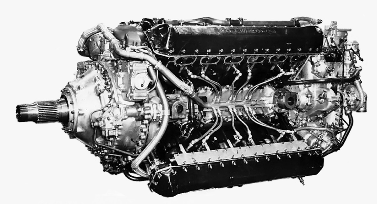
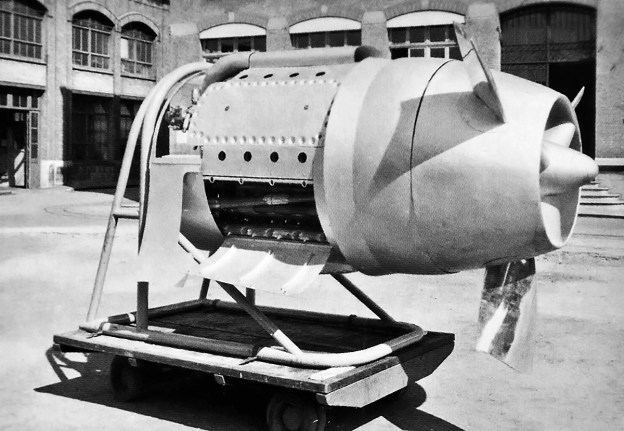
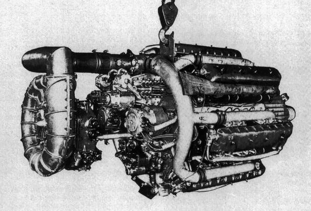
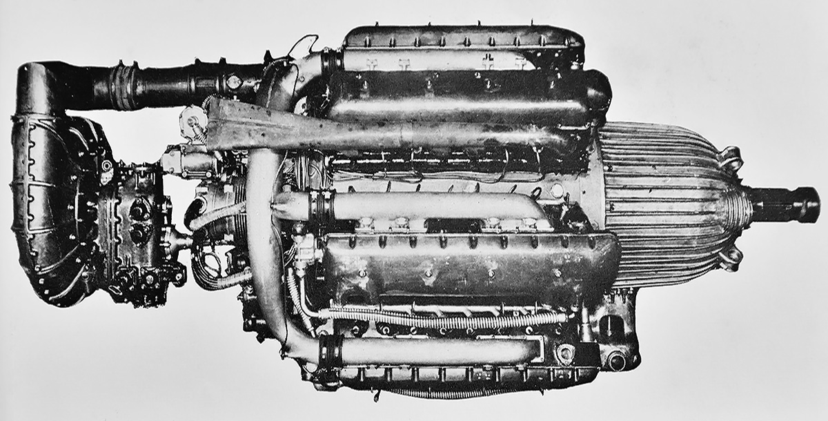
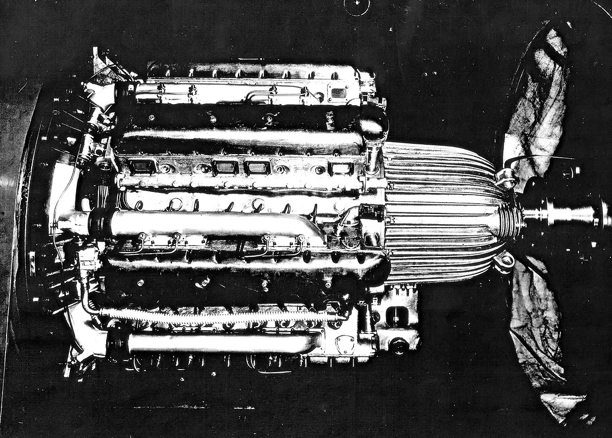
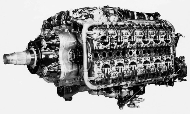
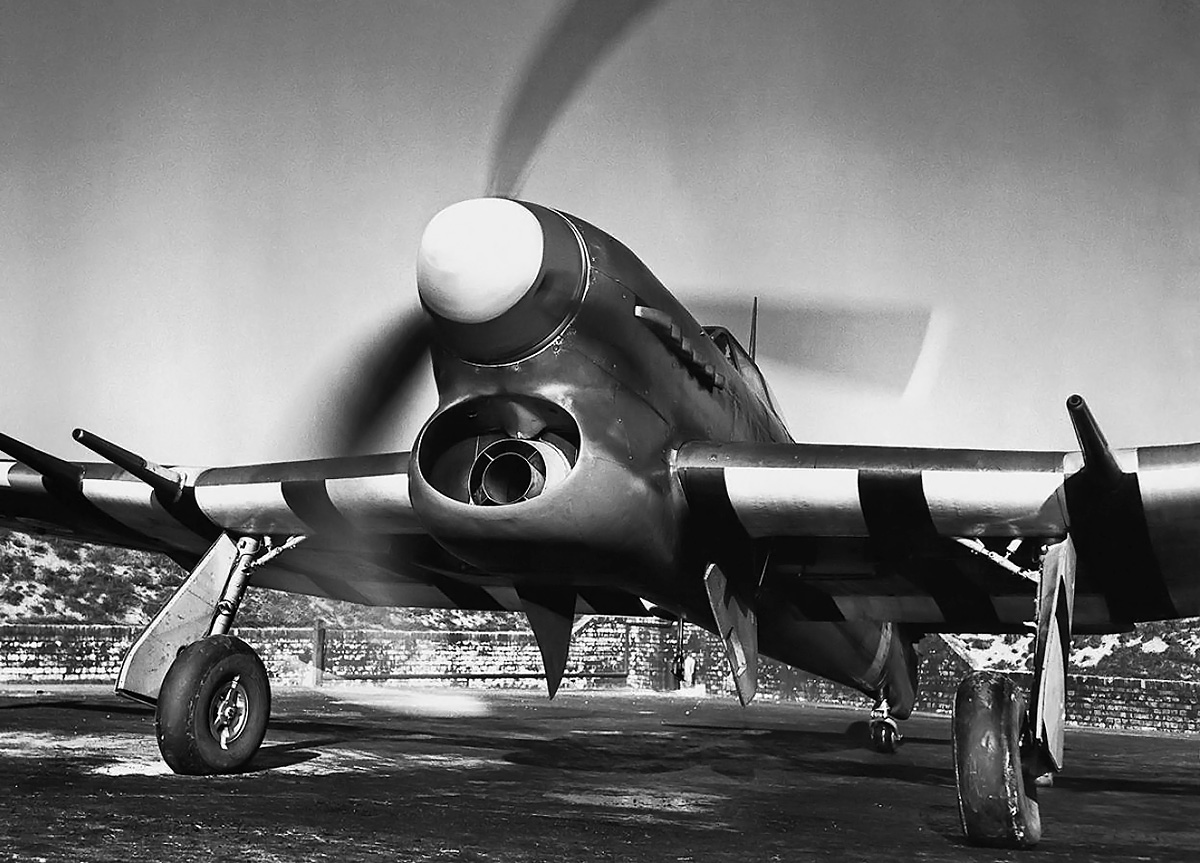
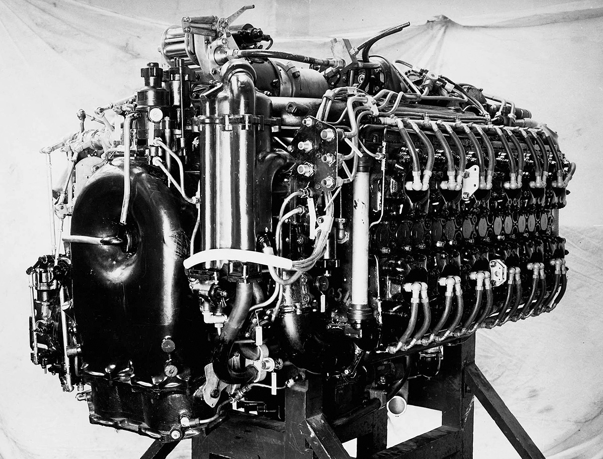
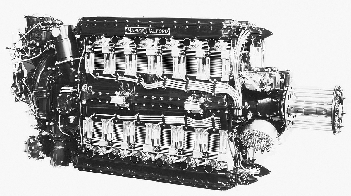
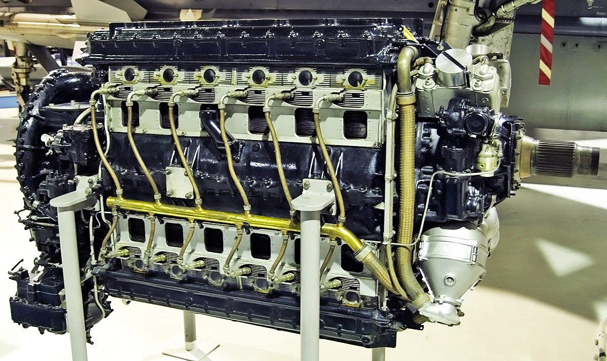
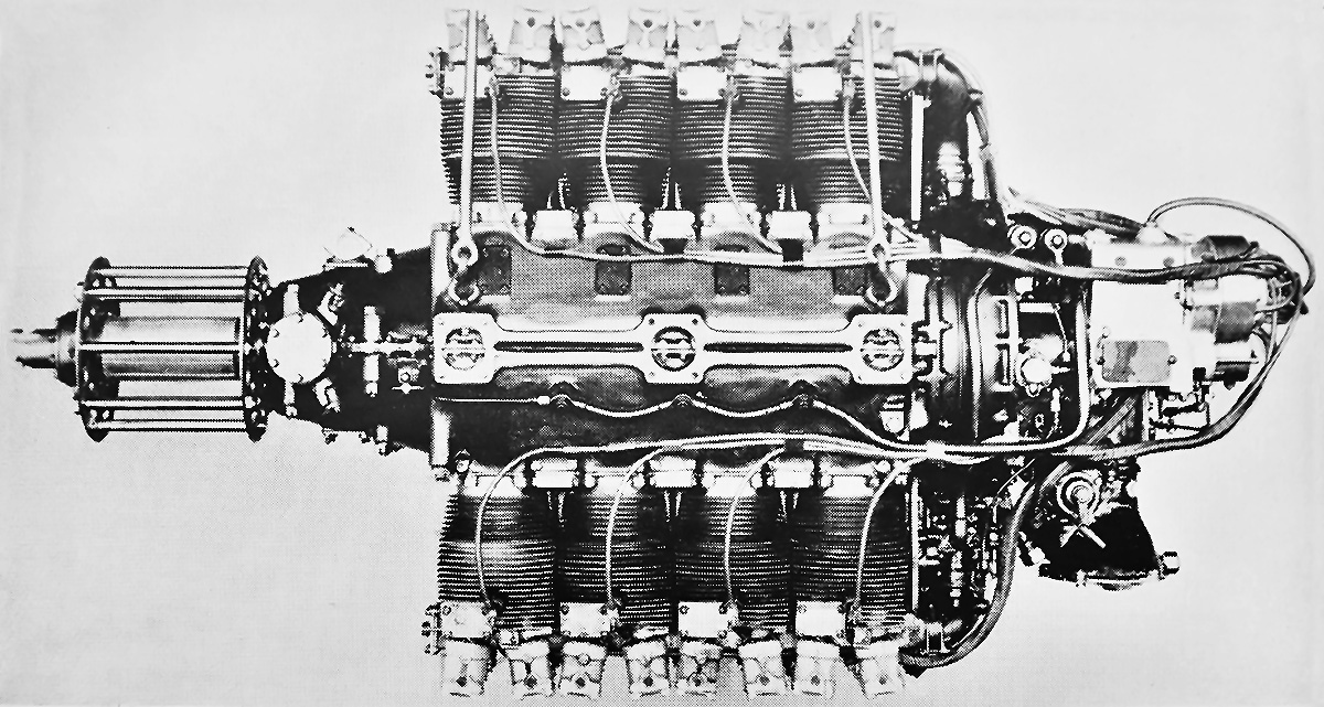
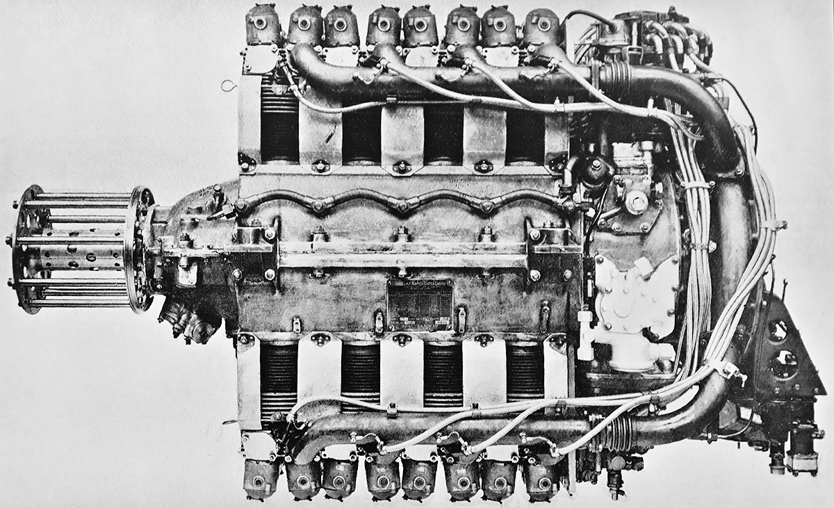
The Napier Sabre’s block-like exterior hid the engine’s complicated internals of 24-cylinders, two crankshafts, sleeve-valves, and numerous drives. The Sabre VA seen here was the last variant to reach quantity production. (Napier/NPHT/IMechE image)

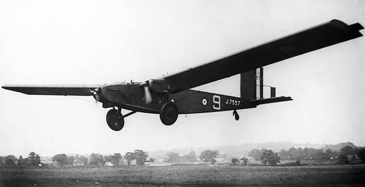
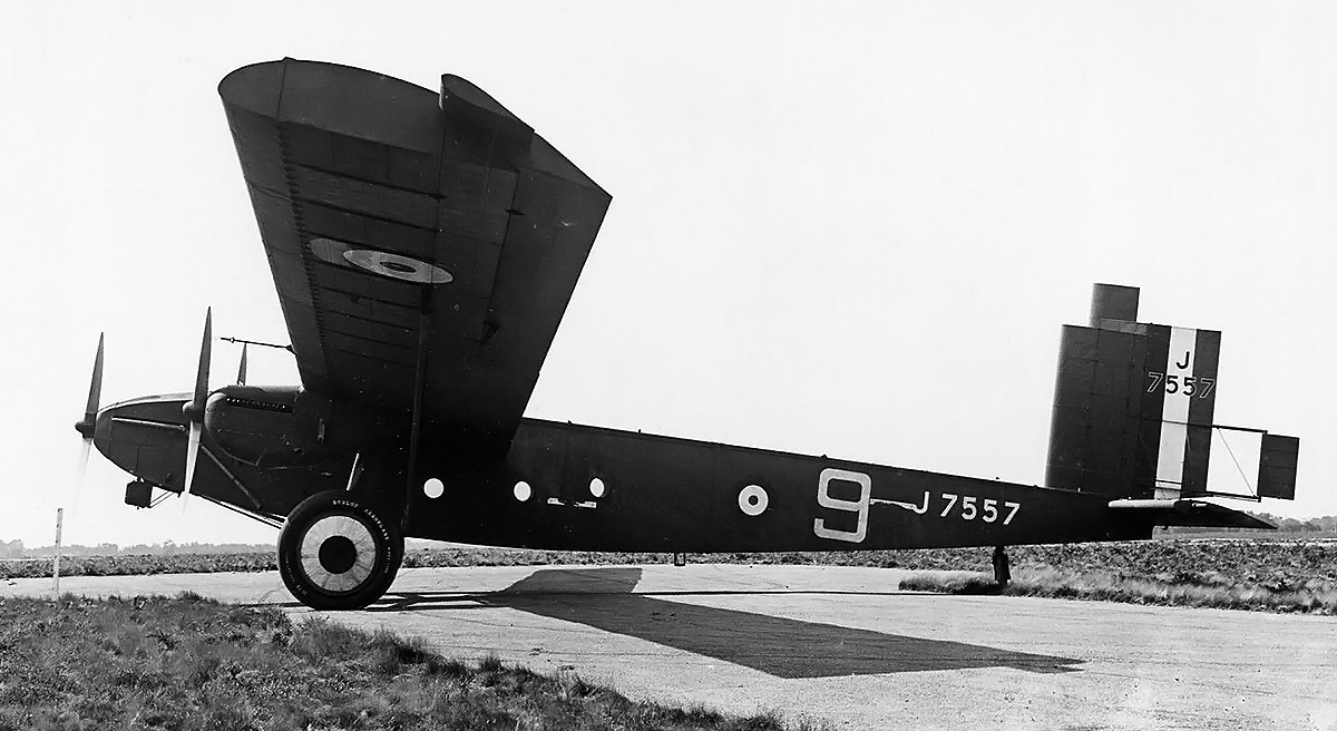
Back around 1930, Napier Chairman Montague Stanley Napier and the company’s Board of Directors sought to diversify into the diesel aircraft engine field. Montague Napier and Bill Nowlan laid out the design for a liquid-cooled, vertical H, 24-cylinder diesel engine that used sleeve valves. Given the Napier designation E101, the engine had a 5.0 in (127 mm) bore, a 4.75 in (121 mm) stroke, and a total displacement of 2,239 cu in (36.68 L). Montague Napier passed away on 22 January 1931, but Nowlan continued design work under the direction of George Shakespeare Wilkinson, Ronald Whitehair Vigers, and Ernest Chatterton. Wilkinson took out a patent for the sleeve drive (GB363850, application dated 7 January 1931), and Vigers took out patents for sealing rings on a plug-type cylinder head (GB390610, application dated 15 February 1932) and sleeve-valves (GB408768, application dated 24 January 1933). It appears the E101 diesel was abandoned around 1933. However, two- and six-cylinder test engines had been built to test the sleeve-drive mechanism and prove the validity of the entire design.

In 1935, Halford joined Napier’s Board of Directors, acting as the company’s Technical Director. Halford was disappointed that the Rapier and Dagger were not more successful. He decided to design a new, larger, 24-cylinder, H-configuration engine that would be capable of 2,000 hp (1,491 kW). The design for at least part of the new engine was based on the E101 diesel. As he had done with the Rapier, Halford showed his design to George Purvis Bulman, the Deputy Director of Engine Research and Development for the British Air Ministry. Bulman was aware that designers of fighter aircraft were interested in such an engine and was able to arrange financial support for Napier to develop the H-24 engine. Halford’s 2,000 hp (1,491 kW) engine was given the Napier designation E107 and became known as the Sabre.

Serious design work on the Sabre started in 1936. The spark-ignition engine had a similar layout to the E101 diesel—both being liquid-cooled H-24s with sleeve-valves and possessing the same bore and stroke. Liquid-cooling was selected to efficiently reject the heat that the compact 2,000 hp (1,491 kW) engine generated, and a mixture of 70 percent water and 30 percent ethylene-glycol would be used. The Air Ministry enabled the free flow of information between Napier, Halford, and Harry Ralph Ricardo—a British engine expert who had been researching sleeve-valve engines for quite some time. With the engine technology known in the early 1930s, a perception existed that the poppet-valve engine had reached its developmental peak. Sleeve-valves were seen as a way to extract more power out of internal combustion engines. The sleeve-valve offered large, unobstructed intake and exhaust ports, a definite advantage to achieve a full charge into the cylinder and complete scavenging of the exhaust when the engine is operating at high RPMs.

Napier-Sabre-II-Cutaway

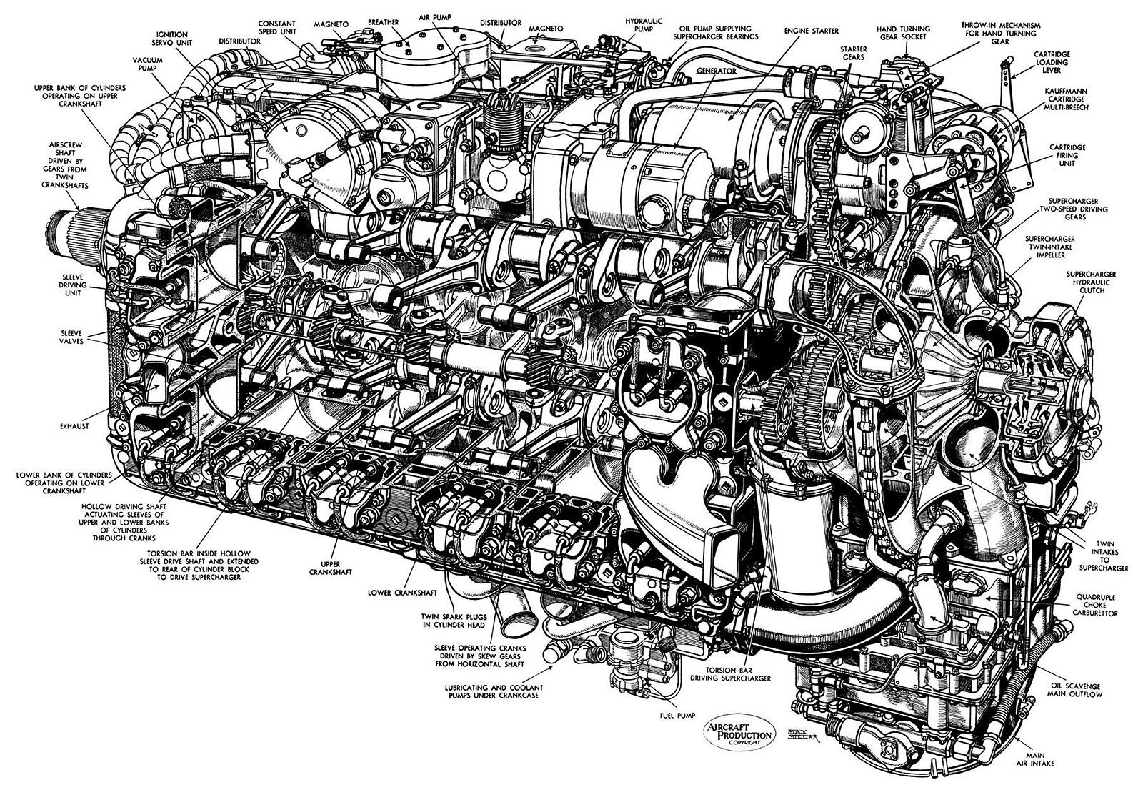
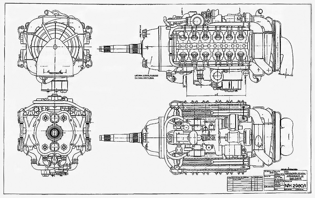
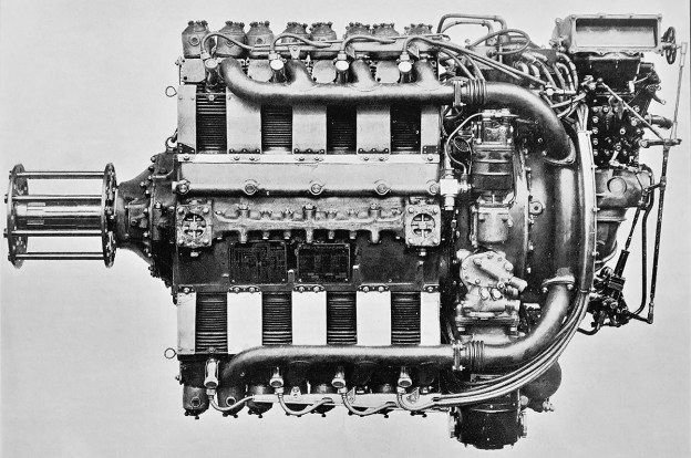
A drawing of a Sabre II, which was the main production variant. Note the two-sided supercharger impeller and the location of the supercharger clutch at the rear of the engine. The design of these components was changed for the Sabre IV and later variants. All accessories are mounted neatly atop the engine, away from any leaking oil, coolant, and fuel. (AEHS image)

The layout of the engine was finalized as a horizontal H-24. The Napier Sabre had a two-piece aluminum crankcase that was split vertically on the engine’s centerline. Sandwiched between the crankcase halves was an upper and lower crankshaft, each secured by seven main bearings. The center main bearing was larger than the rest, which resulted in an increased distance between the third and fourth cylinders in each bank. The crankshafts were phased at 180 degrees, and a cylinder for each crankshaft fired simultaneously. The single-piece, six-throw crankshafts were identical, and both rotated counterclockwise when viewed from the rear of the engine. Fork-and-blade connecting rods were used, with the forked rods serving the three front-left and three rear-right cylinders of the upper banks and the three front-right and three rear-left cylinders of the lower banks.

A 21-tooth spur gear on the front of each crankshaft meshed with two compound reduction gears, each with 31 teeth. A 17-tooth helical gear on the opposite side of each of the four compound reduction gears drove the 42-tooth propeller shaft counterclockwise. The drive setup created a double gear reduction, with the compound reduction gears operating at .6774 times crankshaft speed and the propeller shaft operating at .4048 times the speed of the compound reduction gears. The final gear reduction of the propeller shaft was .2742 crankshaft speed. A balance beam was mounted to the front of the two upper and the two lower compound reduction gears. A volute spring acted on each side of the beam to equally balance the tooth loading of the helical reduction gears on the propeller shaft. The forward ends of the compound reduction gears were supported by a gear carrier plate that was sandwiched between the crankshaft and the propeller shaft housing. The propeller shaft, balance beams, and volute springs were secured by the propeller shaft housing that bolted to the front of the engine.

Napier-Sabre-Sleeve-Drive-Cutaway

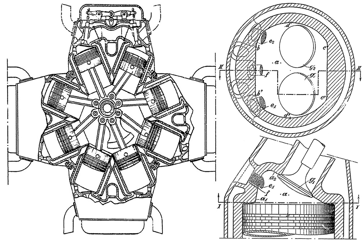
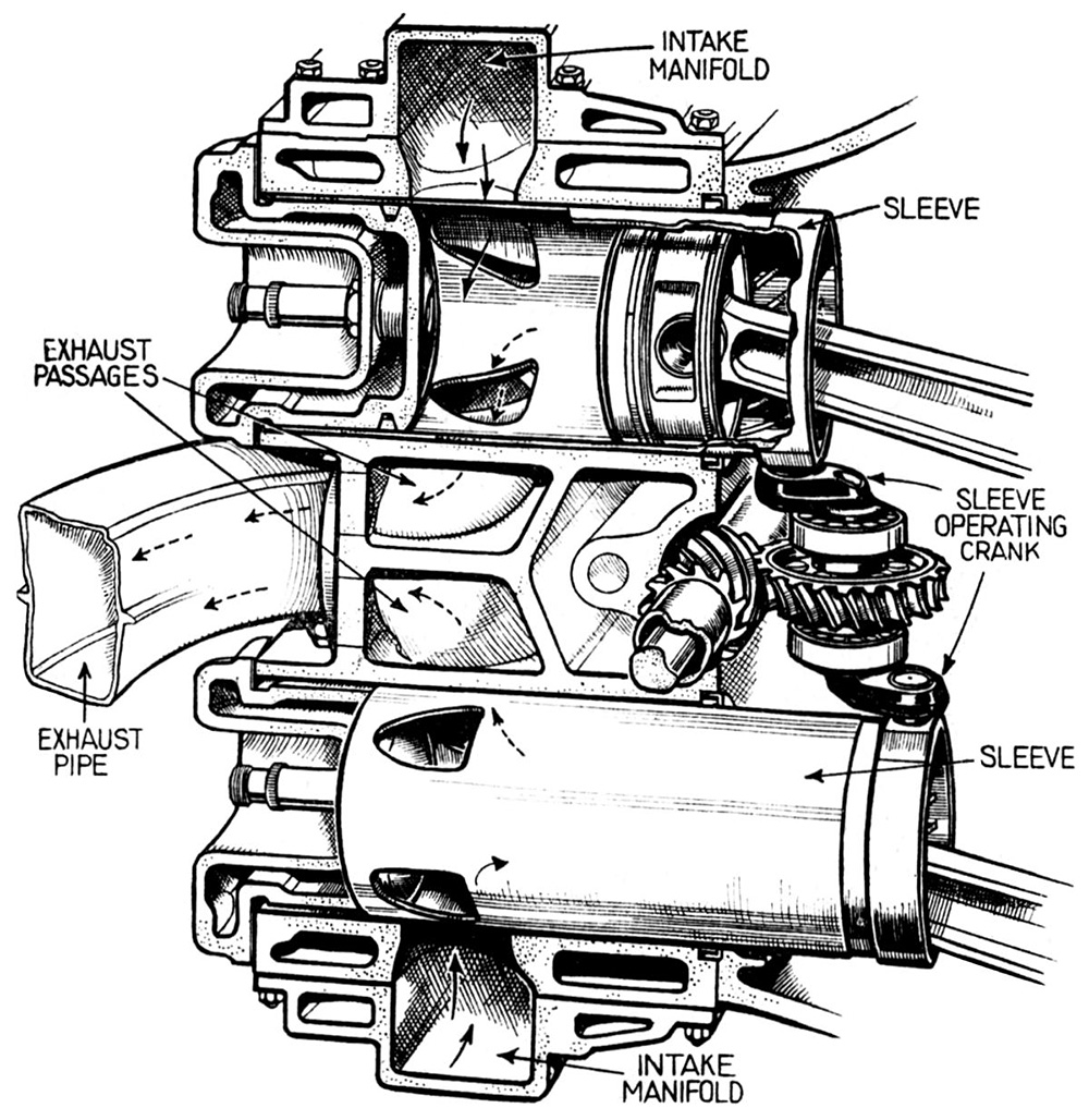
Sectional view through a Sabre cylinder block showing the upper and lower cylinders paired by the sleeve-valve drive. Intake and exhaust passageways were cast into the cylinder block, and coolant flowed through the hollow cylinder head. Note that the sleeve extends quite a distance between the cylinder head and cylinder wall. Also note the supercharger torsion bar extending through the hollow sleeve-valve drive shaft. (AEHS image)

Attached to each side of the crankcase was a one-piece, aluminum cylinder block that consisted of an upper and a lower cylinder bank, each with six cylinders. With the exception of a few installed studs, the left and right cylinder blocks were interchangeable. A two-piece sleeve-valve drive shaft was mounted between each cylinder block and the crankcase, and it ran between the upper and lower cylinder banks. Each sleeve-valve drive shaft was driven at crankshaft speed through a layshaft by an upper compound reduction gear. The left and right sleeve-valve drive shafts each had six worm gears with 11 teeth, and each worm gear drove the sleeves for an upper and a lower cylinder pair via a 22-tooth worm wheel made from bronze. This setup enabled the sleeves to operate at half crankshaft speed (and half the speed of the sleeve-valve drive shaft). The worm wheels and their separate housings were mounted to the inner sides of the cylinder blocks. Each worm wheel had an upper and lower sleeve crank, which were phased at 180 degrees. Each sleeve crank drove a sleeve via a ball joint mounted on a lug on the outer bottom of the sleeve. The rotational movement of the sleeve crank caused the sleeve to reciprocate and oscillate in the cylinder bore. In addition, when the sleeve for the upper cylinder was rotating clockwise, the sleeve for the paired lower cylinder rotated counterclockwise. Due to the opposite rotation, the sleeves for the upper and lower cylinder banks had different (mirrored) port shapes. Each sleeve-valve drive shaft was supported by 14 bearings, with each of the six worm wheel housings incorporating two bearings.

Each sleeve-valve drive shaft was hollow and had a supercharger torsion bar running through its center. The two supercharger torsion bars acted on a compound supercharger gear at the rear of the engine. Via a fluid-actuated clutch, the two-speed supercharger was driven at 4.48 times crankshaft speed in low gear (often called moderate supercharging, MS) and 6.62 times crankshaft speed in high gear (often called full supercharging, FS). The supercharger’s centrifugal impeller was double-sided. Air was drawn in through a four-barrel updraft SU (Skinner’s Union) suction carburetor and fed into the impeller. The air and fuel mixture was distributed from the supercharger housing via one of four outlets to a cast aluminum manifold that ran along the outer side of each cylinder bank.

When ports in the sleeve-valve aligned with three intake ports cast into the cylinder, the air and fuel mixture was admitted into the cylinder. As the sleeve rotated and ascended, the ports closed. Two spark plugs mounted parallel to one another in the cylinder head ignited the mixture, initiating the power stroke. As the sleeve rotated back and descended, the cylinder’s two exhaust ports were uncovered to allow the gasses to escape between the upper and lower cylinder banks. The sleeve’s stroke was approximately 2.5 in (64 mm), and its full rotation was approximately 56 degrees (its rotary movement being approximately 28 degrees back and forth from center). Each sleeve had only four ports, one of which was used for both intake and exhaust. Valve timing had the intake ports opening 40 degrees before top dead center and closing 65 degrees after bottom dead center. The exhaust ports opened 65 degrees before bottom dead center and closed 40 degrees after top dead center. Intake and exhaust ports were simultaneously partially uncovered for 80 degrees of crankshaft rotation—the last 40 degrees of the exhaust stroke and the first 40 degrees of the intake stroke. Twelve exhaust ports were located in a single line on each side of the engine, and each ejector exhaust stack served two ports—one for an upper cylinder and one for a lower cylinder.

Napier-Sabre-parts

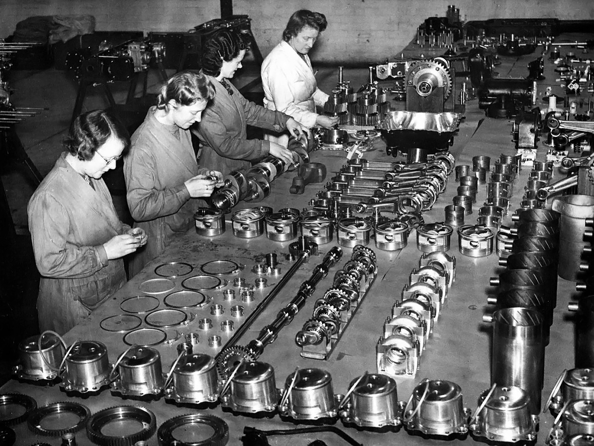
A Sabre engine being assembled. In the foreground are the individual cylinder heads with their sealing rings. In the row above the heads is a long, slim shaft that is the supercharger torsion bar. It passes through the two-piece sleeve-valve drive shaft. Further right are six sleeve-valve cranks, followed by their housings, and a set of 12 sleeves. The crank end of the sleeve is up, and note the helical grooves for oil control. Next is a row of pistons sitting inverted, each with rings and a piston pin. On the next row is a crankshaft being worked on and a set of six fork-and-blade connecting rods. Further to the right is another set of connecting rods that are already attached to the other crankshaft (out of frame). The lady furthest from the camera is working on the four compound reduction gears that will take power from the two crankshafts and deliver it to the propeller shaft, which is being held in a wooden fixture in front of her. On the far left, behind the ladies, is a Sabre cylinder block with numerous studs to attach the cylinder bank. Next is an upper accessory housing with some accessories attached. Last is a lower accessory housing with fuel, water (both external), and oil (internal) pumps.

The forged aluminum pistons were rather short with a minimal skirt, which was required for the engine’s relatively short stroke, use of sleeve-valves, and narrow width. Each flat-top piston had two compression rings above the piston pin, with one oil scraper ring below. The top ring was later tapered to prevent the buildup of carbon. The piston operated directly in the sleeve-valve, which was .09375 in (2.4 mm) thick and made from forged chrome-molybdenum steel. When the piston was at the bottom of its stroke, it was almost completely removed from the cylinder and supported only by the sleeve. The sleeves had a hardened belt on their inner diameter at the top of the piston stroke. Helical grooves inside the lower part of the sleeve helped prevent excessive oil accumulation on the sleeve walls. Oil was controlled further by an oil scraper fitted at the bottom of the sleeve between its outer diameter and the cylinder. The top of each cylinder was sealed by a cast aluminum cylinder head. The cylinder head acted as a plug atop the cylinder and was sealed against the sleeve by a compression ring. The top of the sleeve extended between the cylinder head and the cylinder wall. The cylinder head incorporated coolant passages that communicated with passages in the cylinder block. The engine had a compression ratio of 7.0 to 1.

The upper and lower crankshafts also respectively drove upper and lower auxiliary drive shafts. These auxiliary drive shafts were contained in their own separate housings which were respectively attached to the upper and lower sides of the assembled engine. The upper auxiliary drive shaft powered a vacuum pump, the propeller governor, two distributors, two magnetos, a generator, an air compressor, a hydraulic pump, and an oil pump for the supercharger. All of this equipment was mounted as compactly as possible to the top of the engine. The lower auxiliary drive shaft powered left and right coolant pumps, a fuel pump, and various oil pumps. The coolant and fuel pumps were mounted below the engine, while the oil pumps were internal. The coolant pumps provided a combined flow of 367 US gpm (306 Imp gpm / 1,389 L/min). Also mounted atop the engine and geared to the rear of the upper crankshaft was the Coffman combustion starter unit. The starter had a five-cartridge capacity.

The upper and lower cylinders were numbered 1–12, starting from the left rear and proceeding clockwise to the right rear. With the simultaneous firing of a cylinder for each crankshaft, the engine’s firing order was Top 1/Bottom 6, T9/B10, T5/B2, T12/B7, T3/B4, T8/B11, T6/B1, T10/B9, T2/B5, T7/B12, T4/B3, and T11/B8. Four mounting pads on the underside of the engine attached it to the support structure in the aircraft. The basic design of the Sabre enabled easy access for routine maintenance. Once the aircraft’s cowling was removed, crews had unobstructed access to all of the spark plugs on the sides of the engine and all accessories mounted atop the engine.

Napier-Sabre-IIB-Service-Typhoon-IB

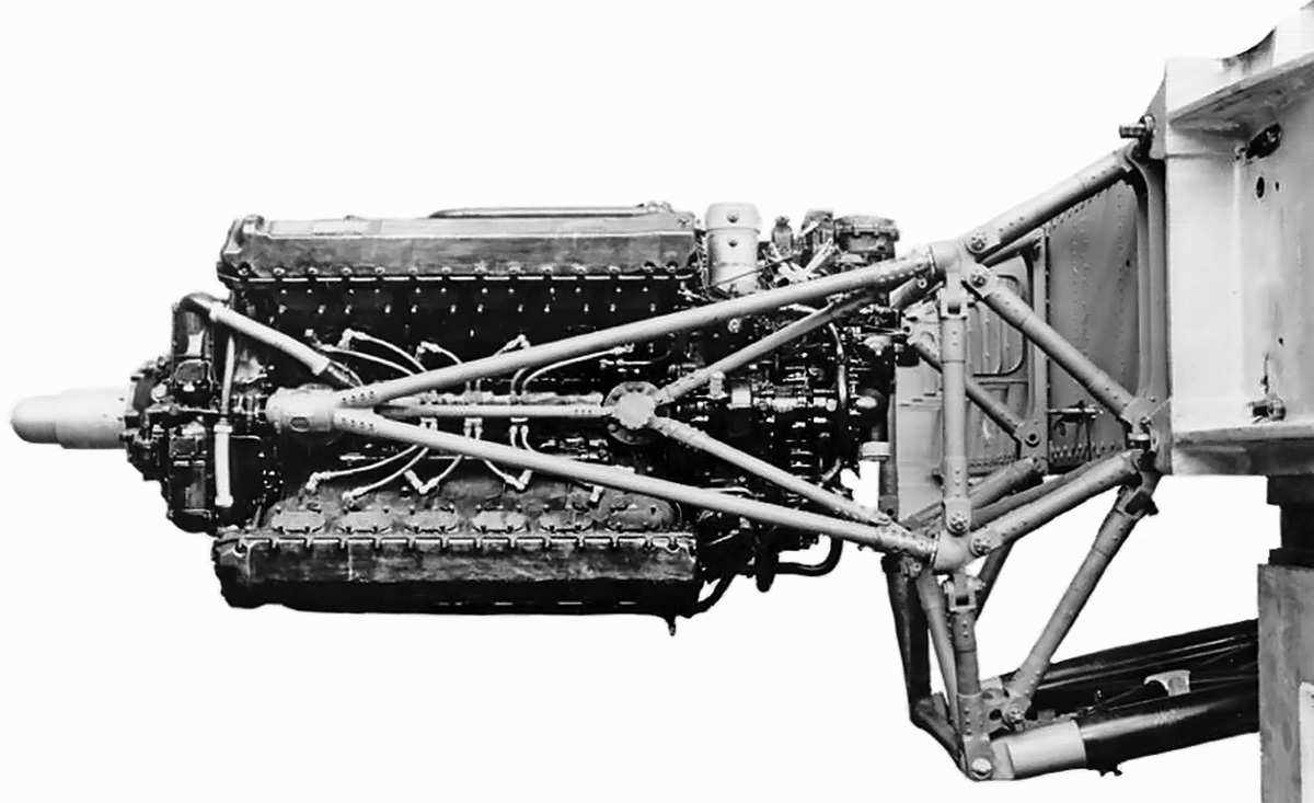
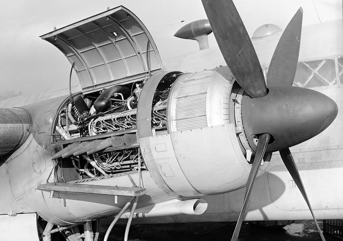
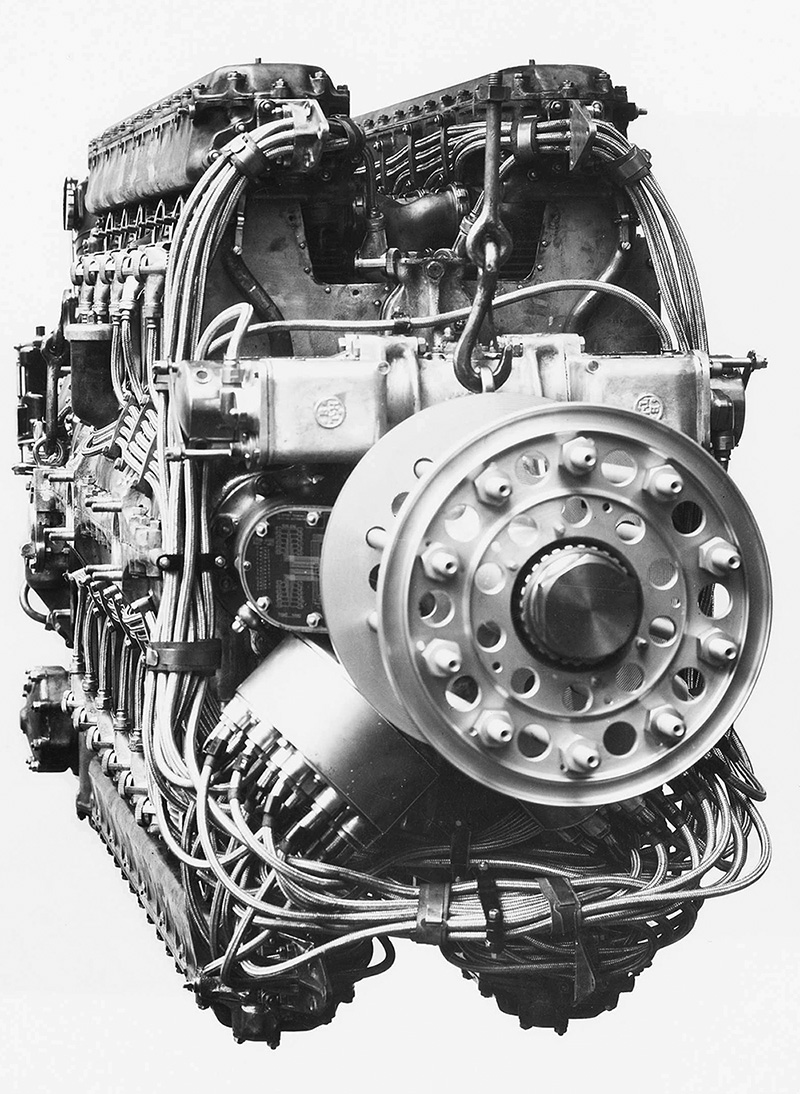
A Sabre IIB being pulled from a Typhoon IB. Note the coolant header tank at the front of the engine, the accessories packaged atop the engine, the two-into-one exhaust stacks, and the hydraulic supercharger clutch at the rear of the engine. The cylinder housing for the five-cartridge Coffman starter can be seen above the supercharger.

The Napier Sabre I (E107) engine had a 5.0 in (127 mm) bore and a 4.75 in (121 mm) stroke. With a bore diameter greater than the stroke length, the Sabre was an over-square engine. Each cylinder displaced 93.2 cu in (1.53 L), and the engine’s total displacement was 2,239 cu in (36.68 L). At 3,700 rpm, the Sabre I produced 2,050 hp (1,529 kW) at 2,500 ft (762 m) with 7 psi (.48 bar) of boost and 1,870 hp (1,394 kW) at 14,500 ft (4,420 m) with 8 psi (.55 bar) of boost. The engine was 81.1 in (2.06 m) long, 40.0 in (1.02 m) wide, and 51.1 in (1.30 m) tall. The Sabre I weighed 2,360 lb (1,070 kg).

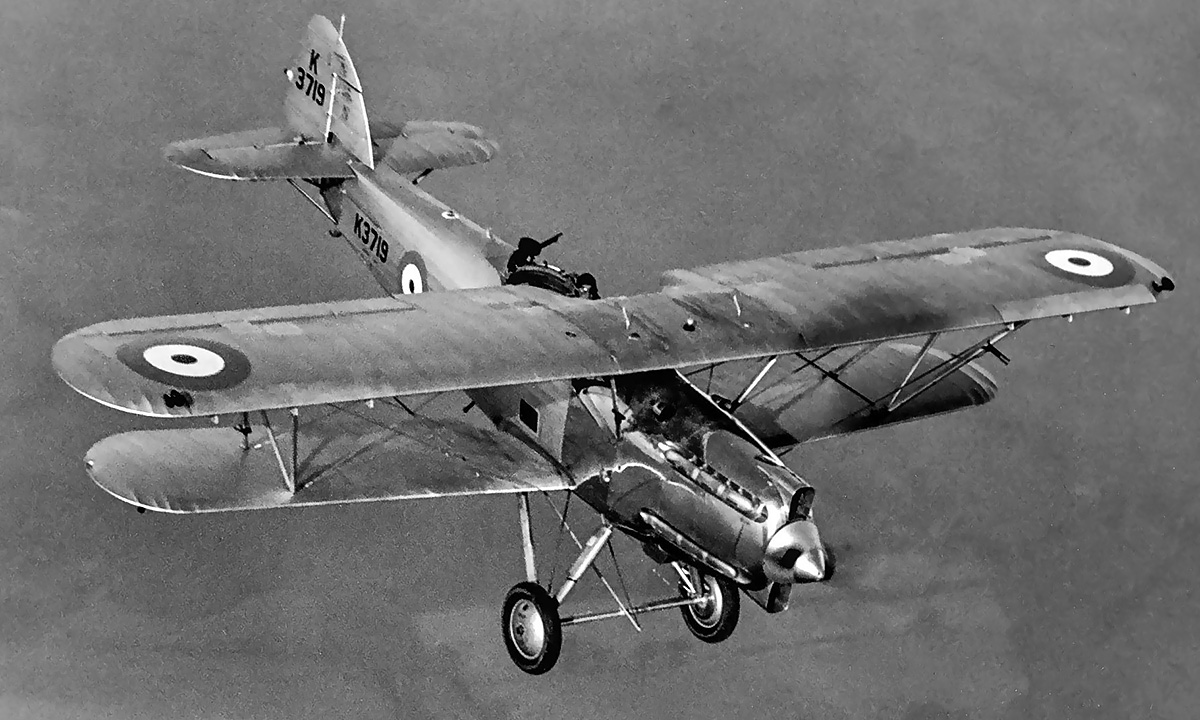
Sabre development at Napier’s works in Acton, England progressed quickly, and single-, twin-, and six-cylinder test engines were all running by the end of 1936. The first of four 24-cylinder prototype engines was run on 23 November 1937, and the Air Ministry ordered six additional test engines by December. On 17 January 1938, the Sabre passed initial acceptance tests with a rating of 1,350 hp (1,007 kW), and on 3 March, the Air Ministry ordered two Sabre-powered Hawker Typhoon fighter prototypes. Also in March, the engine passed a 50-hour test that included a peak output of 2,050 hp (1,529 kW). All ordered engines were completed by the end of 1938 and were running on test stands by February 1939. While testing continued, the Sabre I was first flown in a Fairey Battle on 31 May 1939, piloted by Chris Staniland. As installed in the Battle, the Sabre had a single exhaust manifold on each side of the engine that collected the exhaust from all 12 cylinders.

In July 1939, the Air Ministry ordered 100 production engines and material for another 100 engines. In August, the Sabre passed a type test with a rating of 1,800 hp (1,342 kW). On 8 October 1939, an order for 250 Typhoons was placed, and on 24 February 1940, the Typhoon prototype (P5212) made its first flight, piloted by Philip G. Lucas. Three four-into-one exhaust manifolds were originally installed on each side of the Typhoon’s Sabre, but these were quickly replaced by what would become the standard two-into-one exhaust stacks. In March 1940, Napier created its Flight Development Establishment at Luton, England for flight testing the Sabre and developing installations for the engine. By all accounts, the Sabre continued to perform well, although some vibration issues were experienced with the Typhoon. In June 1940, the engine passed a 100-hour type test with a maximum output of 2,050 hp (1,529 kW) at 3,700 rpm, making the Sabre the first engine to have a service rating over 2,000 hp (1,491 kW).

Fairey-Battle-Napier-Sabre-I-and-Folland-Fo108-Sabre-II

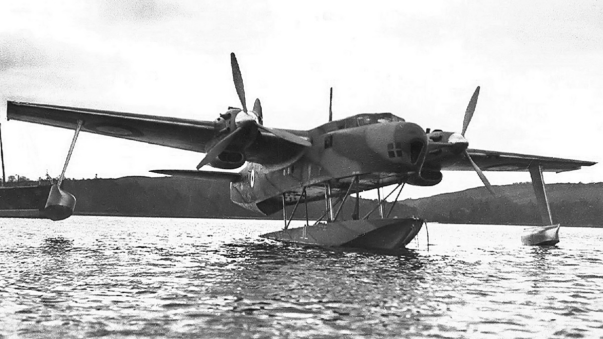
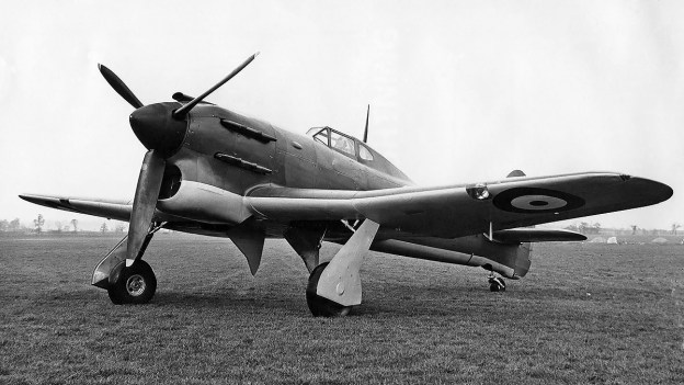
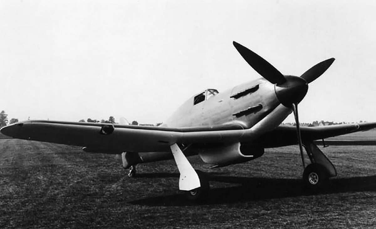
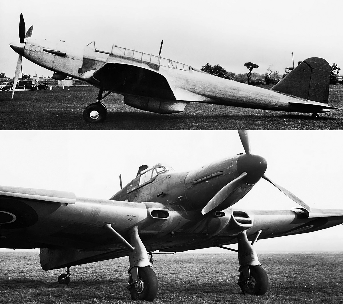
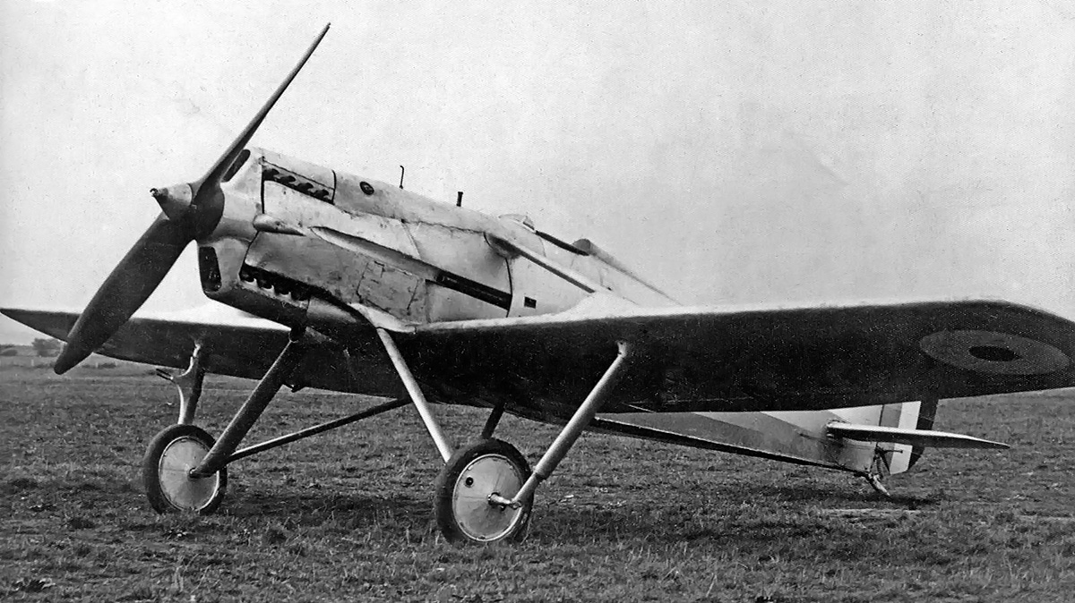
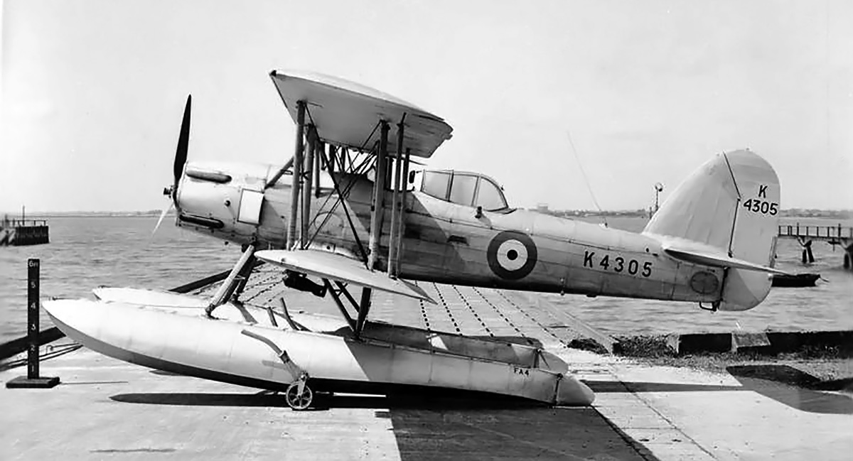
The installation of Sabre engines on the Fairly Battle (top) and Folland F.108 (bottom) were well executed. Two Battles and three Fo.108s were employed to test the Sabre, and these aircraft provided valuable information about the engine.

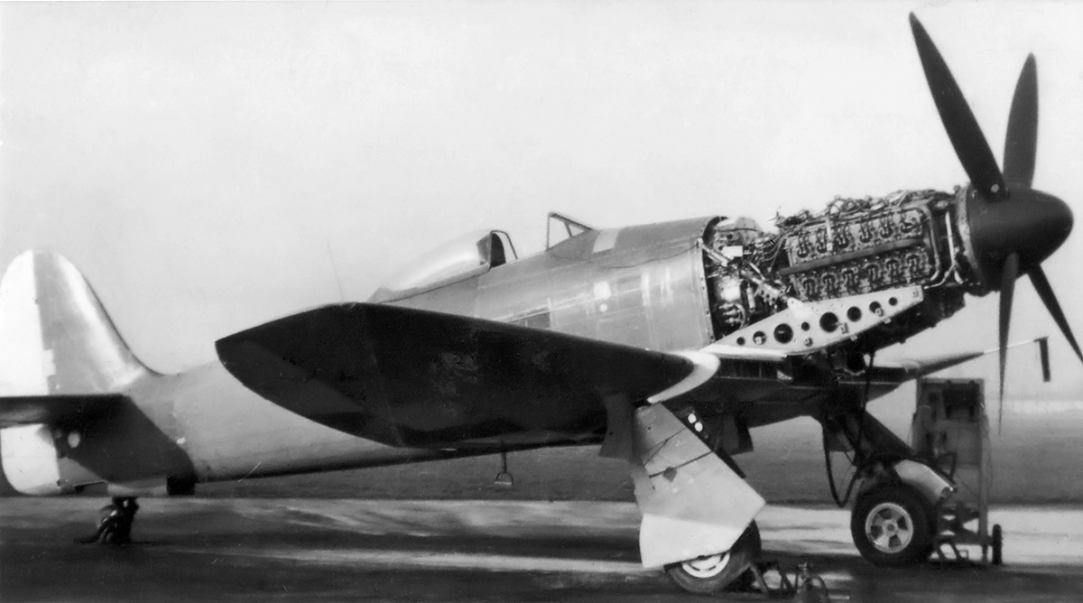
Since mid-1938, a plan was underway to use an uprated Sabre engine in a specially-designed aircraft for a speed record attempt. The special engine produced 2,450 hp (1,827 kW) at 3,800 rpm with 9.2 psi (.63 bar) of boost and was first run on 6 December 1939. Installed in the Napier-Heston Racer, the combination first flew on 12 June 1940, piloted by G. L. G. Richmond. Difficulties with the new engine and airframe resulted in a hard landing that damaged the aircraft beyond repair. The Sabre engine installed in the Napier-Heston Racer featured two six-into-one exhaust manifolds on each side of the engine.

Around November 1939, the Air Ministry ordered 500 examples of the Typhoon. This order was temporarily suspended due to the Battle of Britain but was reinstated in October 1940. At that time, Napier began work to produce additional Sabre engines for the Typhoon order, but production was still a very limited affair. These early engines were limited to 25 hours before being removed for major inspection. The first production Typhoon IA (R7576) flew on 27 May 1941, with other aircraft soon to follow. Nearly all Sabre I engines were used in Typhoon IAs.

Around 1940, consideration was given to producing the Sabre in the United States. A Sabre I was sent to the Army Air Corps Technical Branch at Wright Field, Ohio, where it was inspected by a number of aircraft engine and automotive manufacturers in early 1941. While the engine was judged to be impressive overall, the general consensus was that the Sabre’s complexity and its unproven sleeve-valves made it too much of a risk to justify production in the United States.

Hawker-Typhoon-IB-Napier-Sabre

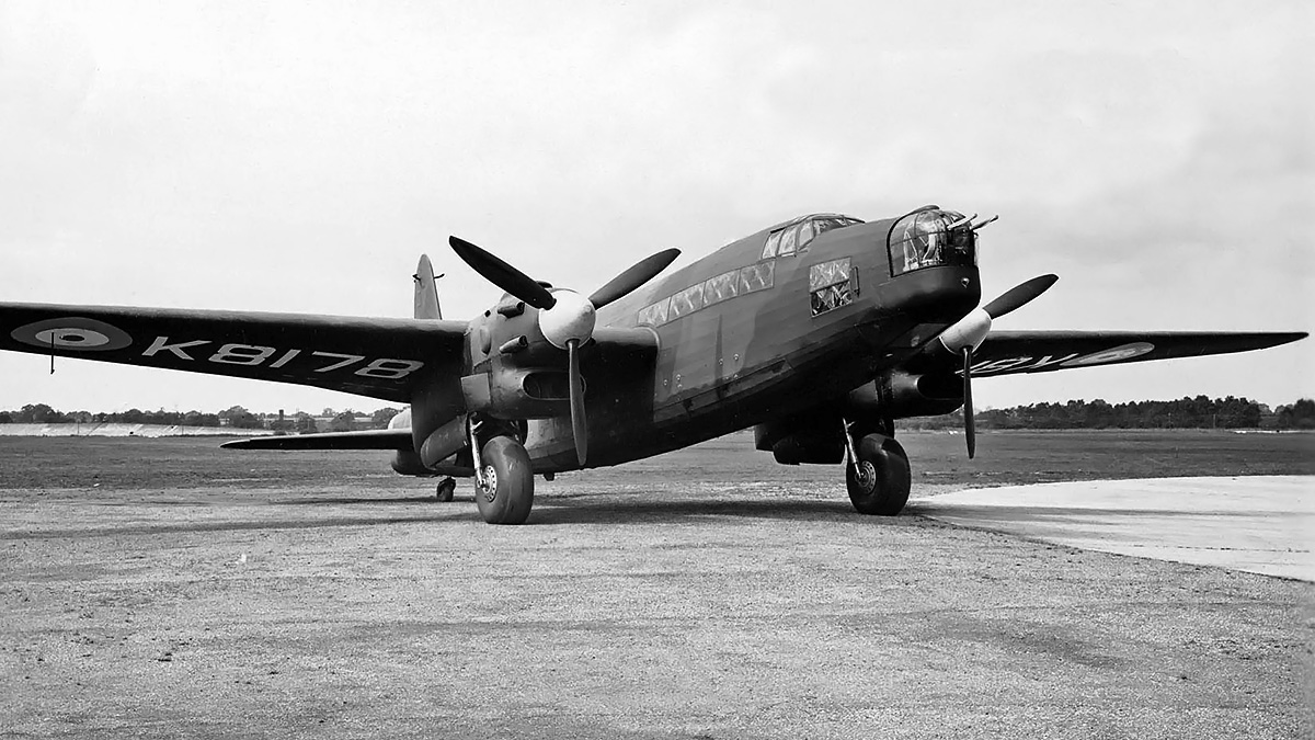
With its 14 ft (4.27 m) three-blade propeller turning, this early Typhoon IB warms up its Sabre engine for a flight. The Typhoon IB had four 20 mm cannons, while the earlier IA had 12 .303 machine guns. At the center of the radiator is the open carburetor intake, which was later covered by a momentum air filter. Note the underwing identification/invasion stripes.

Napier continued to develop the engine as the Sabre II, and the first production Sabre II was completed in January 1941. The Sabre II produced 2,090 hp (1,559 kW) at 3,700 rpm at 4,000 ft (1,219 m) with 7 psi (.48 bar) of boost and 1,735 hp (1,294 kW) at 17,000 ft (5,182 m). Sabre II engines were first installed in Typhoons on a trial basis in June 1941, and the engine was cleared for 50 hours between major inspections around this time. The Sabre II would ultimately replace the Sabre I in Typhoon IAs and IBs, and the Sabre I was phased out around October 1941. In addition to the Typhoon, the Sabre II also powered the Martin-Baker MB3 fighter, which made its first flight on 31 August 1942, and the Hawker Tempest V fighter prototype (HM595), which made its first flight on 2 September 1942, piloted by Lucas. The Tempest V was a new aircraft developed from the Typhoon.

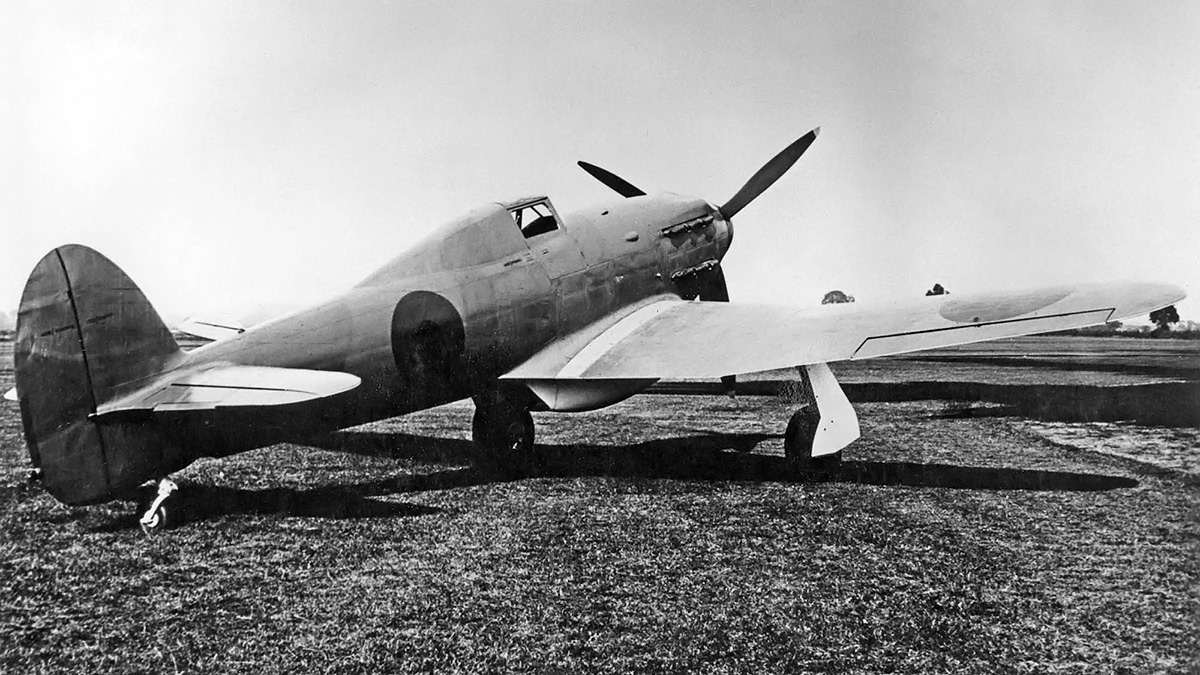
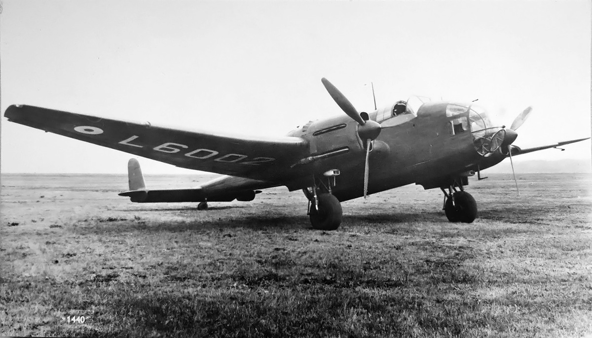
The Folland Fo.108 was built to Air Ministry Specification 43/37 calling for an engine testbed aircraft. Three of the fixed-gear monoplanes were delivered to Napier’s Flight Development Establishment at Luton in 1941 and were initially fitted with Sabre II engines. The aircraft were to serve Napier for several years testing various versions of the Sabre engine. One of the Sabre-powered aircraft was lost on 14 September 1944.

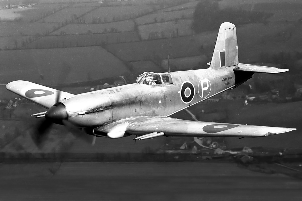
The Sabre III was similar to the II but was intended for higher engine speeds. The Sabre III was selected for the Blackburn B-37 Firebrand carrier strike aircraft. At 4,000 rpm, the Sabre III had a takeoff rating of 2,250 hp (1,678 kW) and military ratings of 2,310 hp (1,723 kW) at 2,500 ft (762 m) with 9 psi (.62 bar) of boost and 1,920 hp (1,432 kW) at 16,000 ft (4,877 m). At 3,500 rpm, the engine had a normal rating of 1,890 hp (1,409 kW) at 5,000 ft (1,524 m) and 1,630 hp (1,215 kW) at 16,500 ft (5,029 m). The Firebrand (DD804) was first flown on 27 February 1942. However, with production priority going to the Typhoon, the Ministry of Aircraft Production decided to reengine the Firebrand with the Bristol Centaurus sleeve-valve radial engine. Only around 24 of the Sabre-powered versions were built.

Blackburn-Firebrand-I-Napier-Sabre

The Blackburn Firebrand, was to be powered by the Sabre III. However, Sabre engine production was allocated to the Typhoon, and the Firebrand was reengined with the Bristol Centaurus. Pictured is DD815, the third Firebrand Mk I prototype.

With production engines in production airframes, Sabre reliability issues were soon encountered. After running for a few hours, sometimes not even passing initial tests, Sabre engines began to experience excessive oil consumption and sleeve-valves cracking, breaking, seizing or otherwise failing. Examinations of numerous engines found sleeves distorted or damaged. Since the Sabre’s main application was the Typhoon, it was that aircraft that suffered the most. To make matters worse, the Typhoon was experiencing its own issues with in-flight structural failures. Other aircraft suffered as well. On 12 September 1942, the Sabre II engine in the MB3 failed; the subsequent crash landing destroyed the prototype and killed the pilot, Valentine H. Baker.

The Sabre had performed admirably during testing, but the production engines were encountering issues at an alarming rate. The early engines were built and assembled by hand. Parts with small variances were matched to obtain the desired clearances and operation. This was a luxury that could not be afforded once the engine was mass produced. The sleeves were found to be .008 to .010 in (.203 to .254 mm) out of round. This caused the cascading failure of other components as the engine was operated. In addition, the piston was forming a ridge in the sleeve, leading to excessive wear and the eventual failure of the piston rings, piston, or sleeve.

Carbon build-up was causing issues with the lubrication system. While in flight, aeration of the oil resulted in a heavy mist of oil flowing from the breather and coating the cockpit, obscuring the pilot’s view. The Coffman cartridge starter caused other issues; its sudden jolt when starting the engine occasionally damaged sleeve-drive components, setting up their inevitable failure. Part of the starting issue was that the sudden rotation of the engine with a rich mixture washed away the oil film between the pistons and sleeves. Finally, service crews were misadjusting the boost controller, creating an over-boost situation that led to detonation in the cylinders and damaged engines.

Hawker-Tempest-I-Napier-Sabre-IV

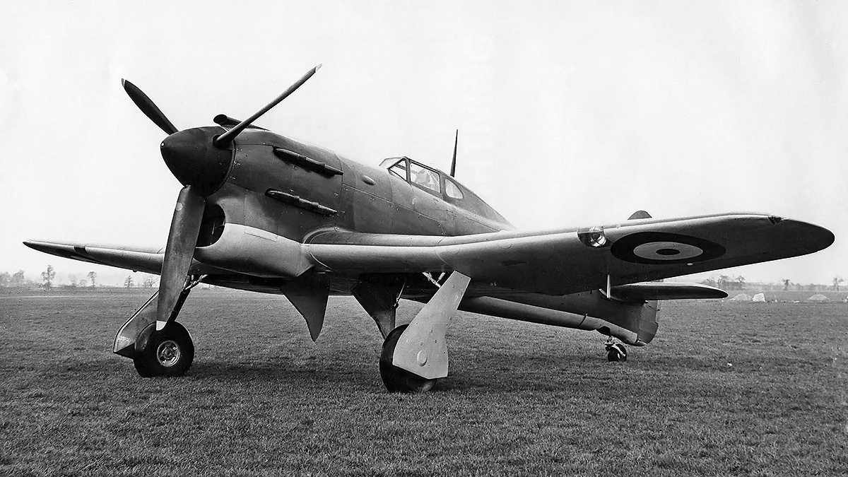
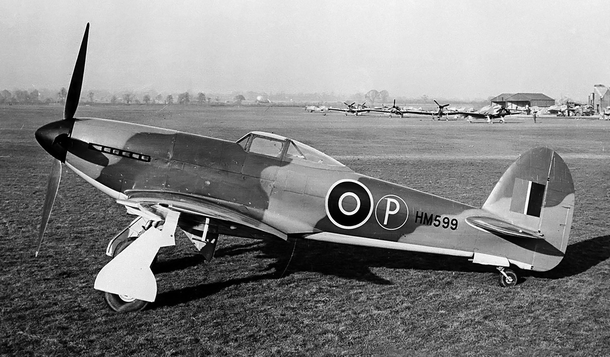
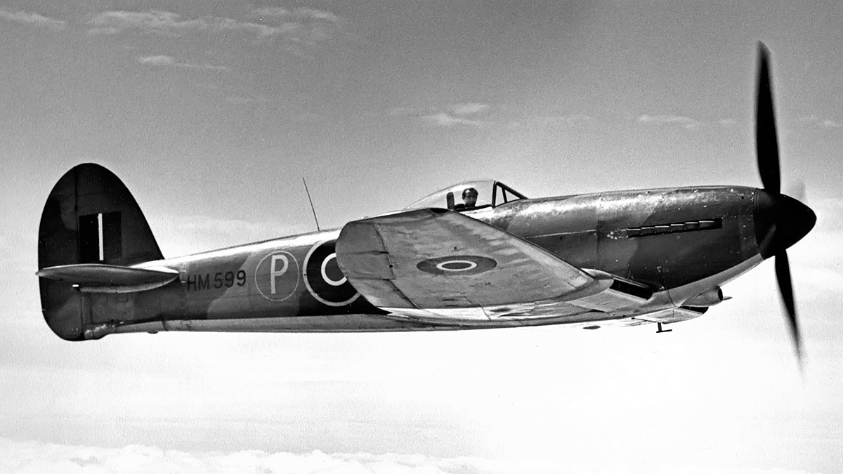
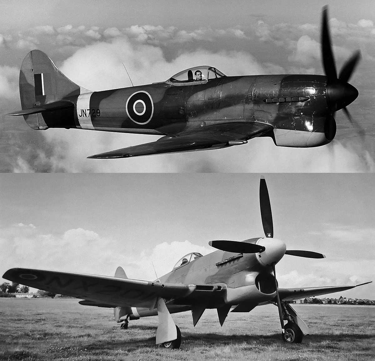
The Tempest I was powered by the Sabre IV engine. At 472 mph (760 km/h), the aircraft was the fastest of the Tempest line. The Tempest I was rather elegant without the large chin radiator, and the wing radiators were similar to those that would be used on the Sabre VII-powered Fury.

Napier worked diligently to resolve the issues. A detergent-type oil was used to prevent the build up of carbon on internal components. A centrifugal oil separator was designed to deaerate the oil and was fitted to Sabre engines already installed in Typhoons. Changes were made to the starter drive, and a priming mixture of 70 percent fuel and 30 percent oil was utilized to maintain an oil film in the cylinders. The boost controllers were factory sealed, and severe repercussions were put in place for their unauthorized tampering.

The issues with sleeve distortion were the most serious and vexing. Methods were devised to measure the sleeve with special instruments via the spark plug hole. While this helped to prevent failures, it also caused the withdrawal of low-time engines as sleeves became distorted. To fix the issue, different sleeve materials were tried along with different processes of manufacture, but nothing seemed to work. The supply of Sabre engines fell behind the production of Typhoon aircraft, and engineless airframes sat useless at manufacturing facilities. The engine shortage was so severe that a good Sabre would be installed in a Typhoon to ferry the aircraft to a dispersal facility. The engine would then be removed, returned to the aircraft factory, and installed in another Typhoon to shuttle that aircraft away, repeating the process over and over.

In October 1941, Francis Rodwell ‘Rod’ Banks replaced Bulman, who was, at the time, the Director of Engine Production for the Ministry of Aircraft Production. Bulman was back in Engine Research and Development and continued to work with Halford and Napier to resolve issues with the Sabre. Banks suggested that Napier work with the Bristol Engine Company on a suitable sleeve for the Sabre. Bristol had been manufacturing radial sleeve-valve engines since 1932, and their Taurus engine had the same 5.0 in (127 mm) bore as the Sabre. Napier was apparently not interested in pursuing that possible solution, so Banks went directly to Bristol and had them machine a pair of sleeves for use in the Sabre two-cylinder test engine. The Bristol sleeves were made from centrifugally cast austenitic steel comprised of nickel, chromium, and manganese. The sleeve was nitrided to increase its hardness and was not more than .0002 in (.005 mm) out of round. The Sabre two-cylinder test engine with the Bristol sleeves ran 120 hours without issue. Banks then had Bristol produce 48 sleeves for two complete 24-cylinder Sabre test engines. Bristol became unhappy with sharing its components and processes with a competitor, and Napier was still hesitant to utilize Bristol’s materials and techniques. Bristol’s position is somewhat understandable considering it took them years and a sizable fortune to develop the materials and procedures to reliably manufacture their sleeves.

Napier-Sabre-VA-rear

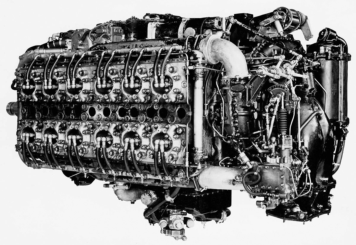
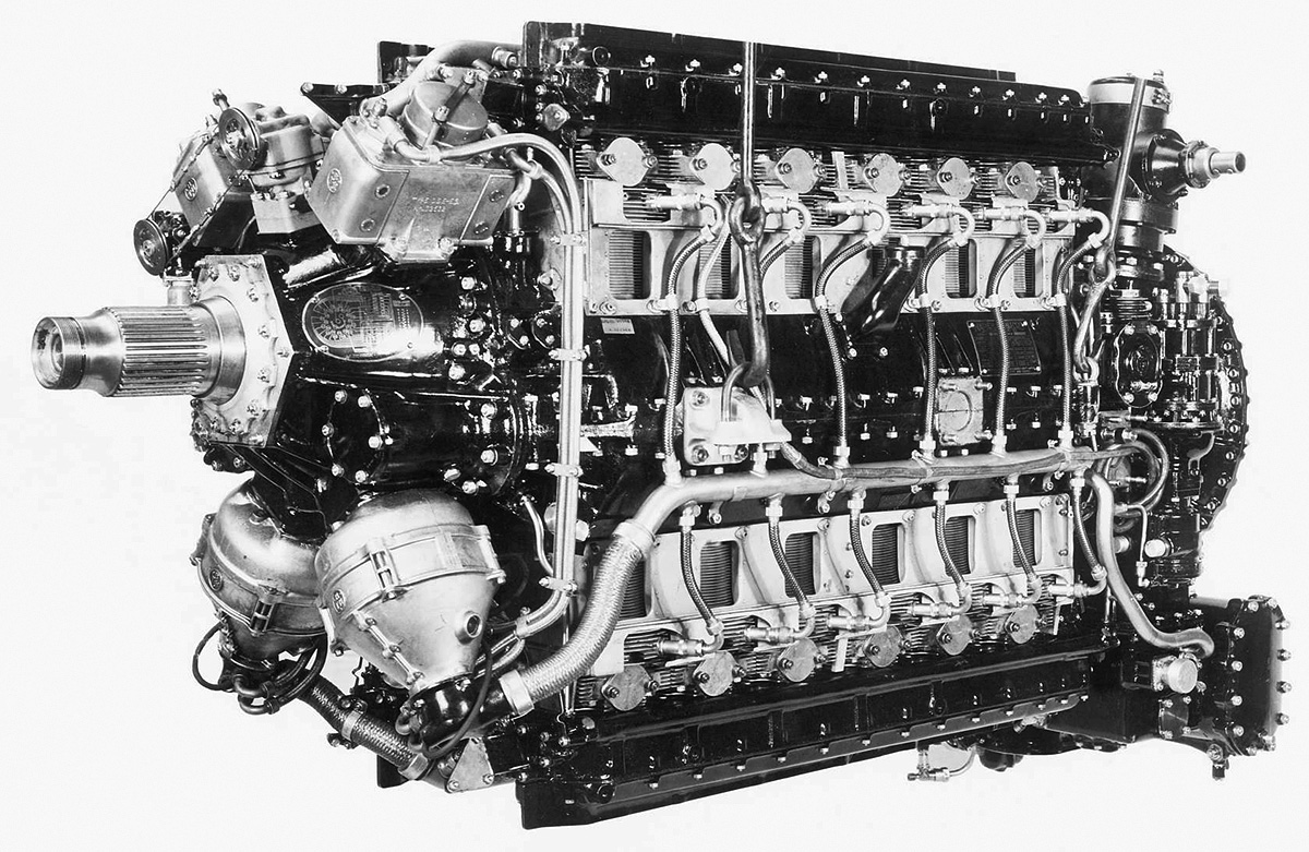
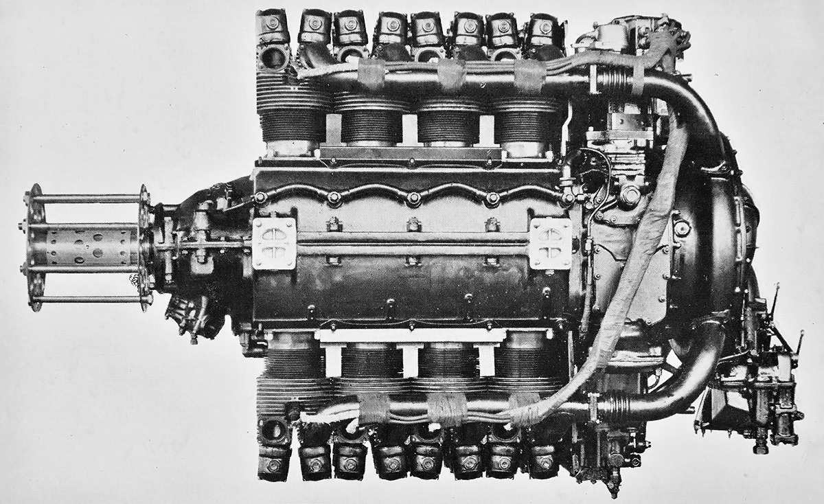
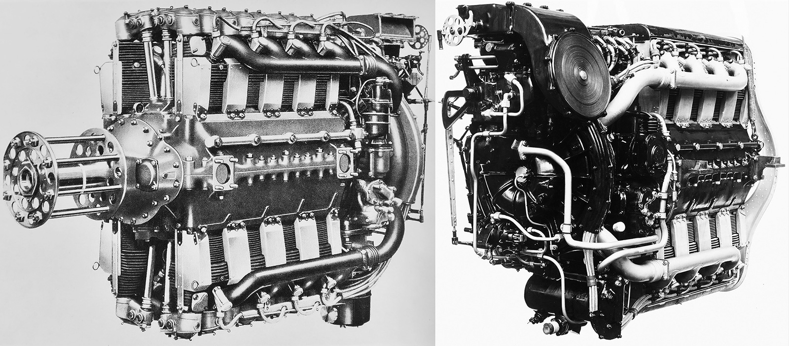
The Sabre VA had a one-sided supercharger impeller, a relocated supercharger clutch, and a two-barrel injection carburetor. These refinements were introduced on the Sabre IV. The Sabre VA powered the Tempest VI. (Napier/NPHT/IMechE image)

With the Air Ministry’s push, Napier was taken over by English Electric in December 1942. The new management was happy to accept any assistance from Bristol, and Bristol was now more willing than ever to lend support. A lack of support from the Napier board of directors had caused Halford to give a three-month notice of resignation, and he left in early 1943 to focus on turbojet engines at the de Havilland Engine Company. Halford was already involved in turbojet engine development at de Havilland before his departure from Napier, and some accused him of neglecting his duties on the Sabre. However, it was the Ministry of Aircraft Production that had previously asked him to get involved with the turbojet. Halford continued consulting work on the Sabre for a time. Before his departure from Napier, Halford’s Sabre designs had progressed up to the Sabre V. Ernest Chatterton took over Sabre development after Halford’s departure. Through all this, Bulman continued to work with Napier, but the Ministry of Aircraft Production handed all responsibility for the Sabre engine to Banks in early 1943. To get engine production up to speed, Sundstrand centerless grinders made in the United States and destined for a Pratt & Whitney factory producing R-2800 C engines were rerouted to Napier’s Sabre production facility in Liverpool. While it is not entirely clear how Banks felt at the time, he later wondered what would have become of the Fairey Monarch H-24 engine if the Air Ministry and the Ministry of Aircraft Production had encouraged its development with the same financial and technological resources supplied for the Sabre.

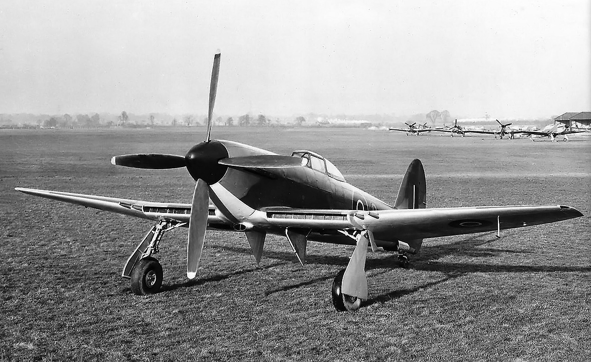
In the spring of 1943, some 1,250 engines had accumulated a total of 12,000 hours of testing and 40,000 hours of service use, and the Sabre’s service life was extended from 25 hours to 250 hours between major inspections. With Sabre reliability issues resolved and production resuming, development of the engine continued. The Sabre IV incorporated a two-barrel Hobson-RAE injection carburetor and a revised supercharger with a single-sided impeller. The supercharger clutches were updated and relocated from the extreme rear of the supercharger to between the supercharger and the engine. Revised gears turned the impeller at 4.68 times crankshaft speed in low gear and 5.83 times crankshaft speed in high gear. The Sabre IV produced 2,240 hp (1,670kW) at 4,000 rpm at 8,000 ft (2,438 m) with 9 psi (.62 bar) of boost. The engine was selected for the Tempest I, the prototype of which was initially ordered on 18 November 1941, followed by an order for 400 production aircraft in August 1942. The Tempest I featured a streamlined nose and its radiator and oil cooler were installed in the wing’s leading edge. The prototype Tempest I (HM599) was first flown on 24 February 1943, piloted by Lucas, and would go on to record a speed of 472 mph (760 km/h) at 18,000 ft (5,486 m) in September 1943. However, delays and development issues with the Sabre IV engine led to the Tempest I order being converted to Sabre IIA and IIB-powered Tempest Vs.

The Sabre IIA (E115) was a refinement of the Sabre II and had been developed in mid-1943. The engine had a modified oil system and used dynamically-balanced crankshafts. The Sabre IIA had a takeoff rating of 1,995 hp (1,488 kW) at 3,750 rpm with 7 psi (.48 bar) of boost. At 3,750 rpm and 9 psi (.62 bar) of boost, the engine had a military rating of 2,235 hp (1,667 kW) at 2,500 ft (762 m) and 1,880 hp (1,402 m) at 15,250 ft (4,648 m). At 3,700 rpm and 7 psi (.48 bar) of boost, the engine had a normal rating of 2,065 hp (1,540 kW) at 4,750 ft (1,448 m) and 1,735 hp (1,294 kW) at 17,000 ft (5,182 m). Fuel consumption at cruise power was .46 lb/hp/hr (280 g/kW/h). Starting around August 1943, Sabre IIA engines were incorporated into production Typhoon IB and Tempest V Series I aircraft.

Napier-Sabre-VA-cutaway

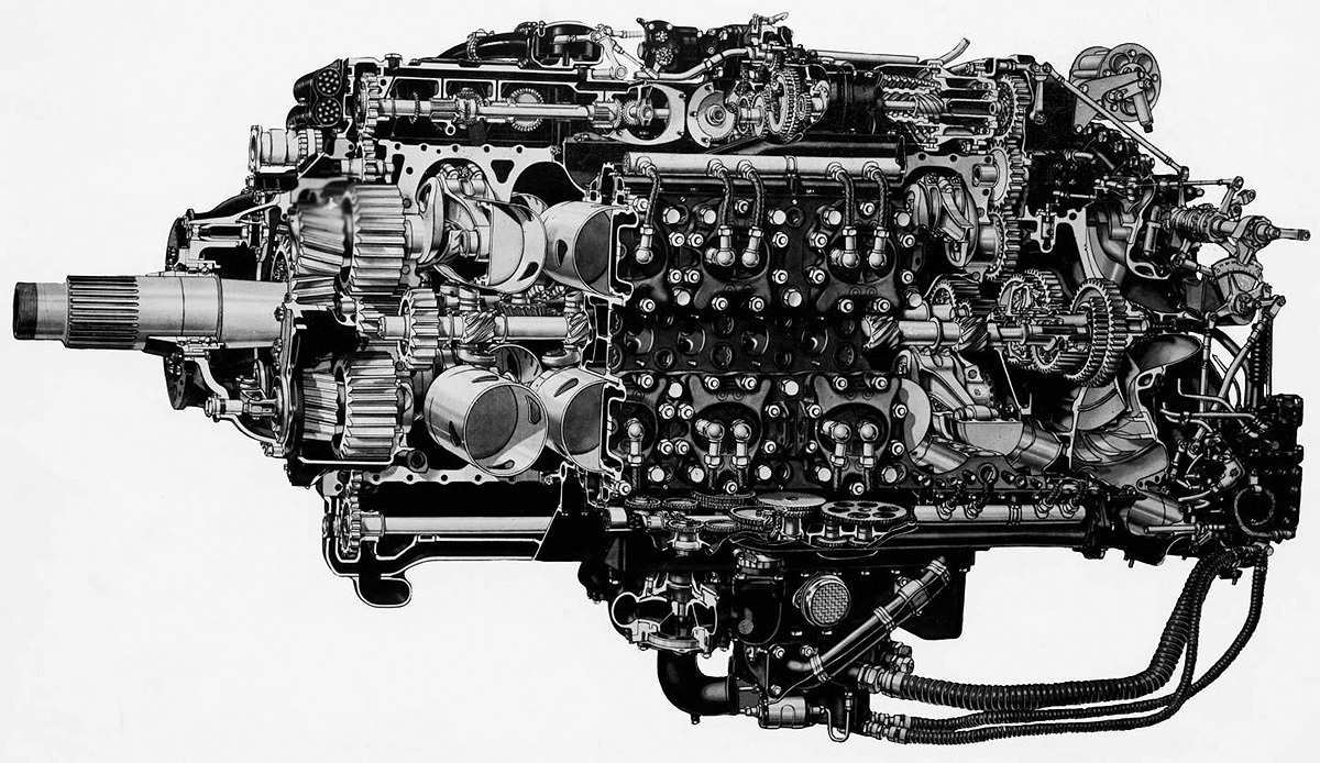
Cutaway drawing of a Sabre VA illustrating the engine’s propeller reduction gears and sleeve-valve drive. Note the upper and lower accessory drives, the slight fore-and-aft angling of the spark plugs, and the single-sided supercharger impeller. (Napier/NPHT/IMechE images)

In 1944, prototypes of the Sabre IIB (E107A) became available. Compared to the Sabre IIA, the IIB used a different carburetor, had a modified boost controller, and was cleared for additional engine speed. The Sabre IIB had a takeoff rating of 2,010 hp (1,499 kW) at 3,850 rpm with 7 psi (.48 bar) of boost. At 3,850 rpm with 11 psi (.76 bar) of boost, the engine had a military rating of 2,400 hp (1,790 kW) at sea level, 2,615 hp (1,950 kW) at 2,500 ft (762 m), and 2,045 hp (1,525 kW) at 13,750 ft (4,191 m). The Sabre IIB had the same normal rating as the IIA. The engine was used in later Typhoon IBs and was the main Sabre version to power the Tempest V Series II.

The Sabre IIC (E107B) was a similar to the IIB but with new supercharger gears. The impeller turned at 4.73 times crankshaft speed in low gear and at 6.26 times crankshaft speed in high gear. The engine had a takeoff rating of 2,065 hp (1,540 kW) at 3,850 rpm. At the same engine speed and with 11 psi (.76 bar) of boost, the military power rating was 2,400 hp (1,790 kW) at 2,000 ft (610 m) and 2,045 hp (1,525 kW) at 13,750 ft (4,191 m). The Sabre IIC was used in some late production examples of the Tempest V, including those converted as target tugs in 1948.

The Sabre V (E107C) was developed from the IV with an updated carburetor. Linkages were incorporated to allow one lever to control the engine’s throttle and the propeller’s pitch along with automatic boost and mixture control, but this system could be overridden by the pilot. The spark plugs were repositioned, although it is not clear if this change was made on the Sabre V or the Sabre VA engine. Rather than being parallel, as in earlier Sabre engines, the electrode of the front spark plug was angled forward, and the electrode of the rear spark plug was angled back. The engine produced 2,420 hp (1,805 kW) at 3,750 rpm at 4,250 ft (1,295 m) with 15 psi (1.0 bar) of boost. The Sabre V was tested in the Tempest I, and the combination was first flown on 8 February 1944 by Bill Humble. On 12 February, an order for 700 Sabre V-powered Tempest Is was issued. This order was later reduced to 300 examples, and then converted to the Sabre V-powered Tempest VI in May. The prototype Tempest VI (HM595 again) made its first flight on 9 May 1944, piloted by Humble. Cooling the more powerful engine in warmer climates required modifications to be incorporated into the Tempest VI, including a larger chin radiator and a secondary oil cooler in the wing. Carburetor inlets were also relocated to the wing’s leading edge. Otherwise, the aircraft was similar to the Tempest V.

Hawker-Tempest-V-and-VI-Napier-Sabre-IIA-and-VA

A Tempest V Series I (top) and Tempest VI (bottom). The Tempest V Series I had Hispano Mk II cannons with long barrels that protruded from the wing’s leading edge. The Tempest V Series II and other Tempests had Hispano Mk V cannons with short barrels. The Sabre VA-powered Tempest VI (bottom) has an enlarged chin radiator, an oil cooler in the wing, and carburetor inlets in both wing roots.

The Sabre VA was essentially the production version of the Sabre V. The Sabre VA had a takeoff rating of 2,300 hp (1,715 kW) at 3,850 rpm with 12 psi (.83 bar) of boost. The engine’s military rating at 3,850 rpm with 15 psi (1.0 bar) of boost was 2,600 hp (1,939 kW) at 2,500 ft (762 m) and 2,300 hp (1,715 kW) at 13,750 ft (4,191 m). At 3,650 rpm, the Sabre VA had a normal rating of 2,165 hp (1,614 kW) at 6,750 ft (2,057 m) and 1,930 hp (1,439 kW) at 18,000 ft (5,486 m). Cruise power at 3,250 rpm was 1,715 hp (1,279 kW) at 6,750 ft (2,057 m) and 1,565 hp (1,167 kW) at 14,250 ft (4,343 m). Fuel consumption at cruise power was .50 lb/hp/hr (304 g/kW/h). The engine was 82.2 in (2.10 m) long, 40.0 in (1.02 m) wide, and 46.0 in (1.17 m) tall. The Sabre VA weighed 2,500 lb (1,134 kg). Starting around March 1946, the engine was the powerplant for production Tempest VI aircraft.

The Sabre VI was the same engine as the Sabre VA, but it incorporated an annular nose radiator and provisions for a cooling fan, all packaged in a tight-fitting cowling. The cooling fan rotated clockwise, the opposite direction from the propeller. The intent of the engine and cooling system combination was to produce a complete low-drag installation package that would cool the engine sufficiently for use in tropical climates. The radiator incorporated cooling elements for both engine coolant and oil.

Hawker-Tempest-V-Napier-Sabre-IIB-ducted-spinner

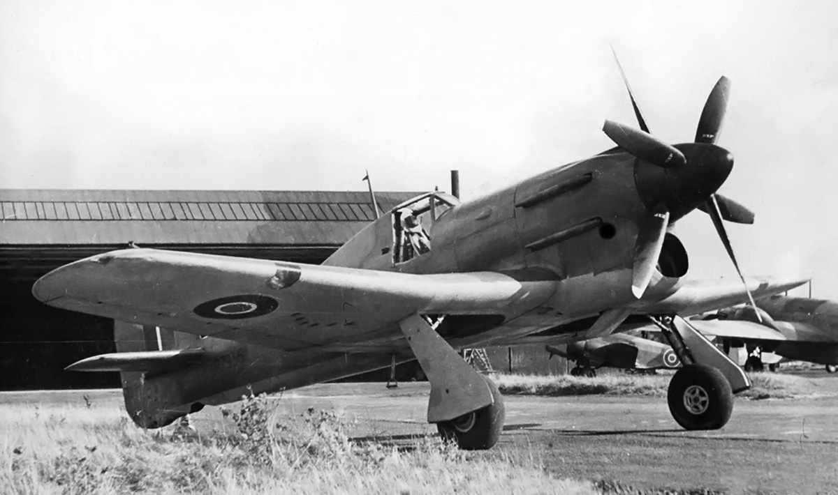
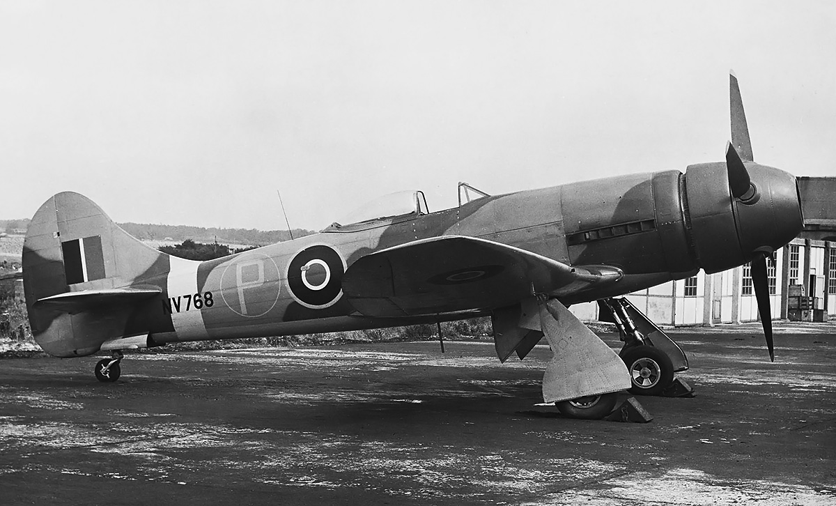
The Sabre VI incorporated an annular radiator and provisions for an engine-driven cooling fan. Tempest V NV768 was used to test a number of different spinner and annular radiator cowling configurations with the Sabre VI. The aircraft is seen here with a large ducted spinner. The configuration slightly improved NV768’s performance over that of a standard Tempest. (Napier/NPHT/IMechE image)

Napier and Hawker experimented with annular radiators using various Sabre IIB engines installed on a Typhoon IB (R8694) and a Tempest V (EJ518). In early 1945, the Sabre VI with an annular radiator was test flown on a Tempest V (NV768). Numerous changes to the annular radiator and its cowling eventually led to the development of a ducted spinner, which was installed on NV768. The aircraft continued to test annular radiators through 1948. While the annular radiator added 180 lb (82 kg), it created only a third of the drag compared to the chin radiator, decreased the aircraft’s overall drag by almost nine percent, and improved the Tempest’s top speed by 12 mph (19 km/h). The annular radiator’s durability was inadvertently tested on 18 December 1944 when EJ518 made a forced, gear-up landing after a hydraulic failure. The annular radiator was undamaged and later installed on NV768. The chin radiator was typically destroyed during a gear-up landing.

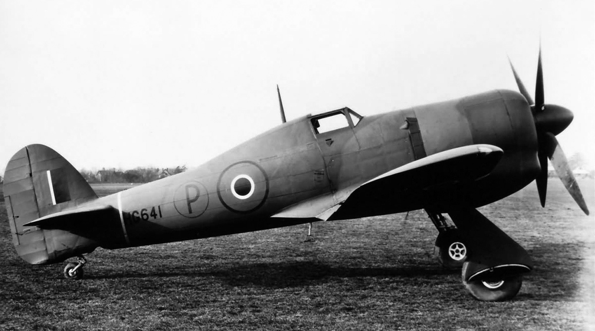
Two Sabre VI engines, each with an annular radiator and a cooling fan, were installed on a Vickers Warwick C Mk III (HG248) twin-engine transport. With the Sabre engines, the Warwick’s top speed was limited to 300 mph (483 km/h) due to its fabric covering. This was still about 75 mph (121 km/h) faster than the aircraft’s original design speed. Most of the annular radiator testing was conducted at Napier’s Flight Development Establishment at Luton. While some of the ducted spinner research was applied to the Napier Naiad turboprop, none of the work was applied to production piston engines.

Napier-Sabre-VI-Vickers-Warwick-CIII

A Vickers Warwick C Mk III (HG248) was used to test the installation of the Sabre VI engine with an annular radiator and an engine-driven cooling fan. Note that the fan rotates in the opposite direction from the propeller and that the lower cowling folds down level to be used as a work platform. The rear four exhaust ejectors were replaced with elongated stacks to prevent excessive heat build-up on the wing’s leading edge. (Napier/NPHT/IMechE image)

The Sabre VII carried the Napier designation E121 and was essentially a VA engine strengthened to endure higher outputs. The engine was fitted with water/methanol (anti-detonant) injection that sprayed into the supercharger via an annular manifold. The mixture used was 40 percent water and 60 percent methanol. The water/methanol injection lowered the engine’s tendency toward detonation and allowed for more power to be produced. The supercharger housing was reworked for the water/methanol injection, and the cylinder heads were modified to accommodate two compression rings. Individual ejector exhaust stacks were fitted, replacing the two-into-one stacks previously used on most Sabre engines.

Initially, the Sabre VII had a takeoff rating of 3,000 hp (2,237 kW) at 3,850 rpm with water/methanol injection and 17.25 psi (1.19 bar) of boost. This was later increased to 3,500 hp (2,610 kW) at the same rpm with 20 psi (1.38 bar) of boost. The engine’s military rating at 3,850 rpm with 17.25 psi (1.19 bar) of boost and water/methanol injection was 3,055 hp (2,278 kW) at 2,500 ft (762 m) and 2,820 hp (2,103 kW) at 12,500 ft (3,810 m). The water/methanol injection flow rate was 76 US gph (66 Imp gph / 300 L/h) at takeoff, 78 US gph (65 Imp gph / 295 L/h) at military power in low supercharger, and 122 US gph (102 Imp gph / 464 L/h) at military power with high supercharger. The water/methanol flow rates corresponded to 30 percent of the fuel flow at low supercharger and 45 percent of the fuel flow at high supercharger. The Sabre VII’s fuel flow was 284 US gph (235 Imp gph / 1,068 L/h) at takeoff, 287 US gph (239 Imp gph / 1,087 L/h) at military power in low supercharger, and 289 US gph (241 Imp gph / 1,096 L/h) at military power with high supercharger. At 3,700 rpm and 10.5 psi (.73 bar) of boost, the Sabre VII had a normal rating of 2,235 hp (1,667 kW) at 8,500 ft (2,591 m) and 1,975 hp (1,473 kW) at 18,250 ft (5,563 m). Cruise power at 3,250 rpm was 1,750 hp (1,305 kW) at 8,500 ft (2,591 m) for a fuel consumption of .45 lb/hp/hr (274 g/kW/h), and 1,600 hp (1,193 kW) at 17,000 ft (5,182 m) for a fuel consumption of .51 lb/hp/hr (310 g/kW/h). The engine was 83.0 in (2.11 m) long, 40.0 in (1.02 m) wide, and 47.2 in (1.20 m) tall. The Sabre VII weighed 2,540 lb (1,152 kg). Some sources state that a Sabre VII engine achieved an output of 4,000 hp (2,983 kW) and was run at 3,750 hp (2,796 kW) for a prolonged period without issues during testing.

Napier-Sabre-VII-rear

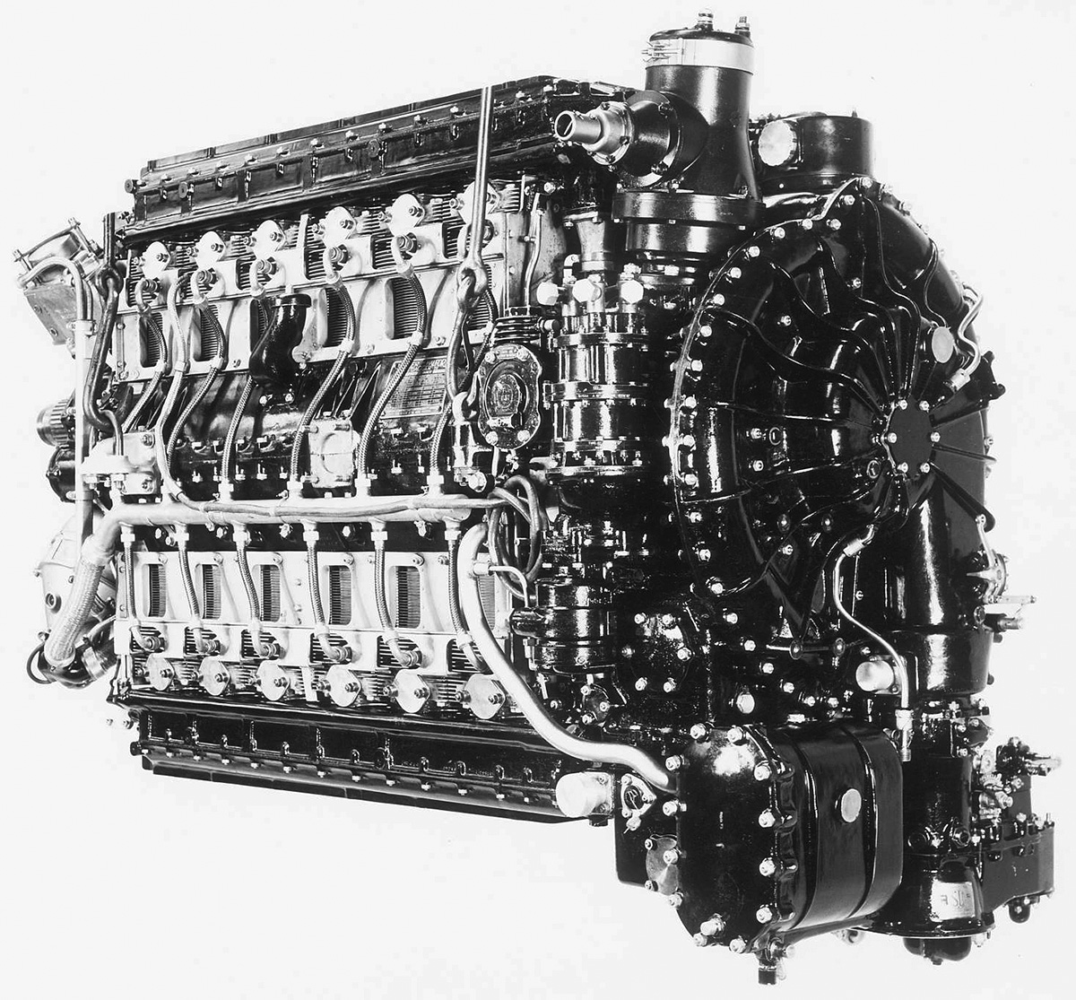
A Sabre VII with its revised supercharger housing that accommodated water/methanol injection. The injection controller is mounted just above the supercharger housing. The Sabre VII ultimately produced 3,500 hp (2,610 kW) at 3,850 rpm with 20 psi (1.38 bar) of boost. (Napier/NPHT/IMechE image)

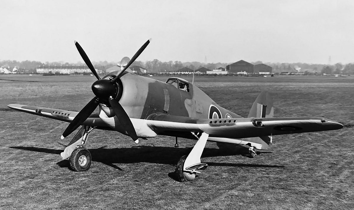
The Sabre VII was intended to power the Hawker Fury Mk I, of which 200 were ordered in August 1944. Shifting priorities at the end of the war all but cancelled the aircraft, and only two prototypes were built. The first prototype (LA610) made its initial Sabre VII-powered flight on 3 April 1946. This aircraft would go on to record a speed of 483 mph (777 km/h) at 18,500 ft (5,639 m) and 422 mph (679 km/h) at sea level. The Sabre VII was also test-flown on a Tempest V or VI in mid-1946, but additional details have not been found. This aircraft had the larger radiator and wing root carburetor inlets of the Tempest VI, but it did not have the additional oil cooler in the wing.

The Sabre VIII carried the Napier designation E122 and was based on the Sabre VII. The engine incorporated contra-rotating propellers and a two-stage supercharger. Four aftercoolers were to be installed—one on each induction runner leading from the supercharger housing to the intake manifold attached to the cylinder bank. Although some sources say the Sabre VIII was built, it appears to have remained an unbuilt project. The engine was forecasted to have a military rating of 3,350 hp (2,498 kW) and be capable of 25 psi (1.72 bar) of boost.

Hawker-Fury-I-Napier-Sabre-VII

The Napier Sabre VII engine installed in the nearly-complete Hawker Fury Mk I prototype. The aircraft and engine combination created a fast and elegant fighter. Note the leading edge wing radiators. (Napier/NPHT/IMechE image)

Production of the Sabre was halted shortly after the end of World War II with approximately 5,000 engines produced. Starting in October 1939, Napier worked to establish a shadow factory in Liverpool to produce Sabre engines. The first engine, a Sabre II, was completed at this factory in February 1942. The Liverpool site manufactured around 3,500 II, IIA, IIB, and VA engines, with the remaining 1,500 engines, including all prototypes, coming from Napier’s Acton works. With Sabre development at an end, Napier focused on their next aircraft engine, the two-stroke diesel/turbine compounded Nomad.

A number of engine designs based on the Sabre were considered, but most stayed as projects, and none progressed beyond cylinder testing. The E109 of 1939 was half of a Sabre, with 12-cylinders and a single crankshaft. It would have displaced 1,119 cu in (18.34 L). The E113 of 1940 was a fuel-injected, two-stroke, uniflow, Sabre-type test engine intended for increased engine speed and boost. The design concept originated with Harry Ricardo, and a two-cylinder test engine was built in 1942. Reportedly, the test engine was so loud that people on the street had to cover their ears as they passed by Napier’s works in Acton. The E120 of 1942 was a 32-cylinder Sabre consisting of four banks of eight cylinders. It would have displaced 2,985 cu in (48.91 L). The E123 of 1943 was a complete 24-cylinder, fuel-injected, two-stroke Sabre based on the E113 test engine. It had a forecasted output of 4,000 hp (2,983 kW) but was never built.

Although the Sabre was proposed for many projects that never left the drawing board and powered a few prototypes, the engine’s main applications were the 109 Typhoon IAs, 3,208 Typhoon IBs, 801 Tempest Vs, and 142 Tempest VIs produced during World War II. After the initial production difficulties, which were quite severe, the engine served with distinction. The Sabre could be difficult to start, and it was advisable to use a remote heater to pre-heat the coolant and oil in cold temperatures. Sleeve trouble came back with Typhoons stationed around Normandy, France in the summer of 1944. Fine dust particles from the soil were getting into the engines and causing excessive sleeve wear. A momentum air filter developed by Napier cured the trouble. The filter was designed and test flown the same day of its original request, and all the Typhoons in France were fitted with a filter within a week. Production of the Sabre was an expensive affair, with each horsepower costing four to five times that of the Rolls-Royce Merlin. However, Typhoons and Tempests played an important role in attacking German forces on the ground and countering V-1 flying bombs. Around a dozen Sabre engines survive and are on display in museums or held in private collections. As of 2020, there are no running Sabre engines, but efforts are underway to create running examples to power Typhoon and Tempest aircraft under restoration.

Napier-Sabre-E122

General arrangement drawing of the unbuilt Sabre VIII (E122). The engine featured a two-stage supercharger and contra-rotating propellers. It was forecasted to produce 3,350 hp (2,498 kW).

Sources:
Major Piston Aero Engines of World War II by Victor Bingham (2001)
Allied Aircraft Piston Engines of World War II by Graham White (1995)
Aircraft Engines Volume Two by A. W. Judge (1947)
By Precision Into Power by Alan Vessey (2007)
An Account of Partnership – Industry, Government and the Aero Engine by George Bulman and edited by Mike Neale (2002)
I Kept no Diary by F. R. (Rod) Banks (1978)
Boxkite to Jet — the remarkable career of Frank B Halford by Douglas R Taylor (1999)
The Napier Way by Bryan ‘Bob’ Boyle (2000)
The Hawker Typhoon and Tempest by Francis K. Mason (1988)
Hawker Typhoon, Tempest and Sea Fury by Kev Darling (2003)
Tempest: Hawker’s Outstanding Piston-Engined Fighter by Tony Buttler (2011)
Hawker Aircraft since 1920 by Francis K. Mason (1991)
Blackburn Aircraft since 1909 by A. J. Jackson (1968/1989)
Aircraft Engines of the World 1945 by Paul H. Wilkinson (1945)
Aircraft Engines of the World 1946 by Paul H. Wilkinson (1946)
Aircraft Engines of the World 1949 by Paul H. Wilkinson (1949)
– “The Napier Sabre Engine Parts 1–3” by J. A. Oates, Aircraft Production Volume 6, Numbers 66–68 (April–June 1944) via The Aircraft Engine Historical Society
– “Napier Sabre II” by F. C. Sheffield, Flight (23 March 1944)
– “Napier Sabre VII” Flight (22 November 1945)
– “Napier Flight Development” Flight (25 July 1946)
Jane’s All the World’s Aircraft 1945/46 by Leonard Bridgman (1946)
Jane’s All the World’s Aircraft 1947 by Leonard Bridgman (1947)
Jane’s All the World’s Aircraft 1948 by Leonard Bridgman (1948)

Napier-Dagger-VIII-front

Napier H-24 Dagger Aircraft Engine

By William Pearce

In 1928, independent aircraft engine designer Frank Bernard Halford was contracted by D. Napier & Son (Napier) to design aircraft engines with a displacement between 404.09 and 718.37 cu in (6.62 and 11.77 L). Halford’s first designs for Napier were the H-16 Rapier (Napier designation E93) of 1929 followed by the inverted I-6 Javelin (Napier designation E97) of 1931.

Napier-Dagger-I-side

The Napier Dagger I air-cooled H-24 with its downdraft carburetor and propeller shaft in line with the engine’s centerline. “Napier Halford” can be seen on the upper camshaft housing. Note the two engine mounts on the side of the crankcase and third mount on the accessory housing. (Napier/NPHT/IMechE image)

Around 1932, Halford and Napier reached a new agreement, and the design of engines larger than the 718.37 cu in (11.77 L) limit were initiated. The first of these designs was a 24-cylinder development of the Rapier with an enlarged bore and elongated stroke. This engine was named the Dagger, and it carried the Napier designation E98. The engine was also called the Napier-Halford Dagger. Like the Rapier, the air-cooled Dagger was a high-revving aircraft engine with numerous small cylinders and minimal frontal area. Halford’s belief was that a smaller engine running at higher speeds would produce the same power as a larger engine running at slower speeds.

The Dagger had a vertical H configuration with four cylinder banks, each with six cylinders. The two-piece aluminum crankcase was split horizontally at its center. The two crankcase halves supported left and right crankshafts via seven main bearings each. An eighth crankshaft bearing was located in the gear reduction housing. Each one-piece, six-throw crankshaft served one vertical and one inverted bank of cylinders. The crankshafts were phased at 30 degrees with power strokes occurring sequentially between the two crankshafts. The connecting rods were of the fork-and-blade type, with the forked rods serving the upper front three cylinders on the left side of the engine and the upper rear three cylinders on the right side of the engine. Spur gears at the front of each crankshaft meshed with a larger gear mounted to the propeller shaft, which turned at .372 crankshaft speed. When viewed from the rear, both crankshafts rotated clockwise, and the propeller shaft rotated counterclockwise.

Napier-Dagger-II-NASM

A Dagger II engine preserved and in storage as part of the Smithsonian National Air and Space Museum. The engine appears complete with its upper and lower air ducts as well as the baffling around the cylinders. At one time, this particular Dagger II belonged to the US Navy. The engine data plate says “Halford-Napier Dagger.” (NASM image)

The individual cylinders were made from forged steel barrels with cast aluminum heads. The heads for each cylinder bank were first installed to a common camshaft housing and then drawn down on the cylinder barrels via four studs protruding from the crankcase around each cylinder opening. An aluminum sealing ring was sandwich between the cylinder head and barrel. The cylinders had a 7.75 to 1 compression ratio, and each cylinder had a single intake and a single sodium-cooled exhaust valve. The intake port was on the inner side of the cylinder, and the exhaust port was on the outer side. The valves for each cylinder bank were actuated via rockers and tappets by a single overhead camshaft. The self-adjusting hydraulic valve tappets were designed by Halford. Each camshaft was driven via a vertical shaft and bevel gears from the rear of the engine.

Each cylinder had one spark plug mounted on its outer side and another mounted on its inner side. The spark plugs were fired by two magnetos mounted to and driven from the gear reduction housing. An accessory drive case was mounted to the back of the engine. A shaft extending back from the propeller shaft powered the accessory drive case. Driven from the accessory case were the camshafts, supercharger, generator, oil and fuel pumps, and various accessories. The single-speed supercharger drew in air through a downdraft carburetor and compressed the air and fuel mixture with a centrifugal impeller. The air and fuel mixture exited the supercharger housing via upper and lower passageways in the crankcase. These passageways were located between the upper and lower cylinder banks, and each had six outlets. A T-shaped manifold that was attached to each induction passageway outlet delivered the air and fuel mixture to two cylinders, one on each bank.

Napier-Dagger-III-side

A Dagger III with individual exhaust stacks and many components chromed and polished to perfection for display purposes. Note the “Napier Halford” placard on the upper camshaft housing. (Napier/NPHT/IMechE image)

For engine cooling, air was ducted between the upper and lower cylinders. Baffles directed the air’s flow through the cylinders’ integral cooling fins and to the outer side of the cylinder banks. The cooling air exited via a cowl flap on each side of the aircraft and behind the engine. Two engine mounting pads were incorporated into the crankcase on each side of the engine. Two integral pads on each side of the rear accessory case were used together to form a third engine mount.

The Napier Dagger I (E98) had a 3.8125 in (96.8 mm) bore and a 3.75 in (95.3 mm) stroke. Each cylinder displaced 42.8 cu in (.70 L), and the Dagger’s total displacement was 1,027 cu in (16.84 L). The engine had a maximum output of 705 hp (526 kW) at 4,000 rpm at 12,000 ft (3,658 m). At 3,500 rpm, the Dagger I had a normal output of 630 hp (470 kW) at 10,000 ft (3,048 m) and produced 570 hp (425 kW) at sea level. The engine was 80 in (2.03 m) long, 22.5 in (.57 m) wide, and 45.125 (1.15 m) tall. The Dagger I weighed 1,280 lb (581 kg).

Napier-Dagger-III-front

Front view of a Dagger III illustrates the engine’s two 24-cylinder distributors mounted under the propeller shaft and the 300 ft (91 m) or so of ignition cables. Just visible between the upper cylinder banks is the T-shaped manifold delivering air to the first two cylinders. (Napier/NPHT/IMechE image)

As engine design was underway, a two-cylinder test engine representing a Dagger’s upper and lower cylinder pair was built and tested. A complete 24-cylinder engine followed and was first run around early 1933. The Dagger I was installed in a two-seat light bomber biplane Hawker Hart (K2434) to serve as a testbed for the engine. The Dagger-powered Hart made its first flight on 17 December 1933. The engine experienced vibration and reliability issues and was later replaced with a Dagger II.

Napier continued to develop the Dagger engine line. Dagger E104 was a test engine with its bore enlarged to 4 in (102 mm). This increased the engine’s displacement by 104 cu in (1.70 L) to 1,131 cu in (18.53 L). It appears the E104 was built up using components from a Dagger I, but the engine never entered production.

The Dagger II was a refined Dagger I with additional supercharging for higher altitudes. The engine had a maximum rating of 760 hp (567 kW) at 4,000 rpm at 12,250 ft (3,734 m) with 1.5 psi (.10 bar) of boost, a normal rating of 695 hp (518 kW) at 3,500 rpm at 10,000 ft (3,048 m) with 1.5 psi (.10 bar) of boost, and a takeoff rating of 710 hp (529 kW) at 3,500 rpm with 3.0 psi (.21 bar) of boost. Fuel consumption at cruise power was .420 lb/hp/hr (255 g/kW/h). The Dagger II weighed 1,305 lb (592 kg). The engine was first run around early 1934 and passed a 100-hour type test on 18 June 1934. The Dagger II made its first flight in Hawker Hart K2434 in January 1935. Like the Dagger I, the Dagger II needed further work before the engine could enter production.

Napier-Dagger-VIII-front

The Dagger VIII incorporated many changes from the previous Dagger engines and was capable of 1,000 hp (746 kw). Note the propeller shaft’s position has been raised above the engine’s centerline. (Napier/NPHT/IMechE image)

The Dagger III (E105) was a moderately supercharged version of the Dagger II. The engine had a maximum output of 805 hp (600 kW) at 4,000 rpm at 5,000 ft (1,524 m) with 2.25 psi (.15 bar) of boost, a normal output of 725 hp (541 kW) at 3,500 rpm at 3,500 ft (1,067 m) with 2.25 psi (.15 bar) of boost, and a takeoff output of 755 hp (563 kW) at 3,500 rpm with 3.5 psi (.24 bar) of boost. Fuel consumption at cruise power was approximately .448 lb/hp/hr (273 g/kW/h). Hawker Hart K2434 again served as a testbed and first flew with the Dagger III around September 1935. The improved engine was found to be reliable and was selected for the Hawker Hector, a two-seat liaison biplane. Hart K2434 was used to develop the engine cowling and installation for the Hector, and the Dagger III entered production in 1936. The Hector was first flown on 14 February 1936, and 179 examples were built. By June 1937, the Dagger III had completed a 100-hour test run at 4,000 rpm. Its initial output was record as 850 hp (634 kW). The engine was also selected for the Martin-Baker MB2 monoplane fighter, which made its first flight on 3 August 1938, but only the prototype was built. The Hector served in World War II, but the aircraft required extra maintenance due to its tight cowling and problematic Dagger III engine and was never a favorite of ground crews.

Napier-Dagger-VIII-rear

Rear view of a Dagger VIII highlighting the engine’s supercharger housing that conceals a two-sided impeller. The updraft carburetor can be seen on the right side of the engine. (Napier/NPHT/IMechE image)

In 1937, Dagger E108 incorporated several major changes. The engine had a double-entry, two-sided supercharger impeller for increased boost and incorporated an updraft carburetor. The propeller gear reduction housing was redesigned to accommodate a controllable-pitch propeller and moved up approximately 3.5 in (90 mm) above the engine’s centerline. The raised propeller shaft enabled the use of a larger diameter propeller. The relocation of the propeller shaft and redesign of the gear reduction housing resulted in the accessory drive shaft being powered by the left crankshaft, and the right crankshaft drove the magnetos and distributors mounted to the nose case. The propeller gear reduction was lowered to .308. New cylinders were designed with finer and more numerous cooling fins. Cylinder compression ratio was decreased slightly to 7.5 to 1. A single mounting pad on each side of the accessory case replaced the two pads previously used. Dagger E108 produced 935 hp (697 kW) at 4,100 rpm at 9,750 ft (2,972 m), and the engine was developed further as the Dagger VIII.

For the Dagger VIII, Napier developed a nose cowling with air ducts between the upper and lower cylinders. This was done in an attempt to make sure that the engine, once installed in an aircraft, was properly cooled. The Dagger VIII (E110) was first run in 1938 and had a maximum output of 1,000 hp (746 kw) at 4,200 rpm at 8,750 ft (2,667 m) with 5.0 psi (3.4 bar) of boost. The engine was rated at 925 hp (690 kW) at 4,000 rpm at 9,000 ft (2,743 m) with 4.0 psi (.28 bar) of boost and 955 hp (712 kW) for takeoff at 4,200 rpm with 6.0 psi (.41 bar) of boost. Its cruising output was 830 hp (619 kW) at 3,600 rpm at 7,000 ft (2,134 m) with 3.5 psi (.24 bar) of boost. Fuel consumption at cruise power was .461 lb/hp/hr (280 g/kW/h). The Dagger VIII was 73.9 in (1.88 m) long, 24.4 in (.62 m) wide, and 47.8 in (1.21 m) tall. The engine weighed 1,390 lb (630 kg).

Hawker-Hector

A Hawker Hector with its Dagger III was the most successful application of the engine in an airframe. However, maintenance crews did not like the engine or its tight cowling.

In March 1937, the Dagger VIII was selected for what would become the Handley Page HP.53 Hereford I, a twin-engine medium bomber monoplane. The Hereford was simply a Dagger-powered HP.52 Hampden, and 100 examples were ordered in August 1937. The selection of the Dagger engine was more out of necessity than desirability. With all the other orders coming in during the scramble to rearm in the late 1930s, an alternative powerplant was desired to substitute for the standard Bristol Pegasus engines in the Hampden. The Hereford prototype (L7271) made its first on 8 October 1938. Cooling issues were encountered during flight trials, and the cowlings were modified and redesigned several times. The first production Hereford I (L6002) first flew on 17 May 1939. Persistent issues with the Dagger engines resulted in most of the 100 Herefords ordered being finished with Pegasus engines, since Pegasus production was able to keep up with demand. The few Herefords that retained their Dagger engines were used mostly as trainers. The Dagger VIII was also installed in Fairey Battle K9240 for engine tests. The Dagger VIII-powered battle made its first flight in November 1938.

The last of the Dagger line was the E112. This was an enlarged Dagger with a 4.0625 in (103 mm) bore, a 3.9375 in (100 mm) stroke, and a total displacement of 1,225 cu in (20.07 L). The E112 engine design dated from around 1939 and may have been a development of E104. It does not appear that the E112 was ever built.

Handley-Page-HP.52-Hereford-I

The first Handley Page HP.52 Hereford I production aircraft (L6002) with its Dagger VIII engines. The cowling was similar to that developed for the Rapier. Note the carburetor intake under the engine and the cooling air exit door on the side of the rear cowling.

Like the Rapier, cooling the Dagger engine was difficult while the aircraft was on the ground. Cylinder head temperatures would often reach their upper limit before oil temperatures reached their lower limit. The result was that an aircraft would take off with oil temperature too low. This affected the oil’s ability to flow and led to the failure of various internal engine components. The Dagger did not achieve a level of success that warranted the engine’s mass production. However, what production there was of the Rapier and Dagger was enough to keep Napier going. The British Air Ministry was somewhat sympathetic to the powerful, compact, high-revving, small-frontal-area aircraft engine concept and continued to support Napier and Halford. By 1939, Napier was fully focused on developing the 2,000 hp (1,491 kW) Sabre engine for the war in Europe. While the air-cooled Dagger H-24 may have contributed to the knowledgebase upon which the liquid-cooled Sabre H-24 was built, the engines were very different. A Dagger II is preserved and in storage as part of the Smithsonian National Air and Space Museum. One Dagger VIII is on display at the Royal Air Force Museum in London, England and another is part of the Science Museum’s collection at Wroughton, England.

Napier-Dagger-VIII-RAF

A Dagger VIII engine preserved and on display at the Royal Air Force Museum in London, England. Note the baffles on the cylinders to direct the flow of cooling air through the fins. (Nimbus227 image via Wikimedia Commons)

Sources:
Aero Engines Vol. II by Various Authors (1939)
British Piston Aero-Engines and Their Aircraft by Alec Lumsden (2003)
By Precision Into Power by Alan Vessey (2007)
Boxkite to Jet — the remarkable career of Frank B Halford by Douglas R Taylor (1999)
Aircraft Engines Volume Two by A. W. Judge (1947)
Jane’s All the World’s Aircraft 1935 by C. G. Grey (1935)
Jane’s All the World’s Aircraft 1939 by C. G. Grey (1939)
Aerosphere 1939 by Glenn D. Angle (1940)
Aircraft Engines of the World 1941 by Paul H. Wilkinson (1941)
An Account of Partnership – Industry, Government and the Aero Engine by George Bulman and edited by Mike Neale (2002)
Hawker Aircraft since 1920 by Francis K. Mason (1991)
Fairey Aircraft since 1918 by H. A. Taylor (1974/1988)
Handley Page Aircraft since 1907 by C. H. Barnes (1976)
– “The Napier-Halford Daggers” Flight (11 July 1935)
– “Accent on the Aspirate” Flight (10 June 1937)
– “The Napier Dagger VIII” Flight (12 January 1939)

Napier-Rapier-VI

Napier H-16 Rapier Aircraft Engine

By William Pearce

Frank Bernard Halford had been an aircraft engine designer since World War I. In 1923, he established himself as a for-hire consultant to design aircraft engines for established manufacturers. By 1927, Halford had designed a new high-revving aircraft engine with numerous small cylinders and minimal frontal area. Halford’s belief was that a smaller engine running at a faster speed would produce the same power as a larger engine running at a slower speed. The new engine design was a vertical H with four cylinder banks, each with four individual cylinders.

Napier-Rapier-I

The Napier Rapier I with its intake and exhaust ports mounted on opposite sides of the cylinder, Note the magnetos mounted to the rear of the engine and the external oil line on the crankcase.

Halford showed the design to George Purvis Bulman, the Chief Inspector (of engines) for the British Ministry of Munitions. Bulman was impressed with the design and knew that the British engineering firm D. Napier & Son (Napier) was in search of a new product. Napier’s Lion W-12 aircraft engine was designed 10 years previous, and the company had stopped producing automobiles in 1924. Napier wanted to pursue the development of new aircraft engines but felt that its current in-house design department did not have the needed experience.

Bulman introduced Halford to George Pate, Napier’s Production Chief Engineer. With the blessing of Napier’s board of directors and its chairman, Montague Stanley Napier, Halford was contracted in 1928 to design aircraft engines for Napier. One stipulation was that the engines must fall between a displacement of 404.09 and 718.37 cu in (6.62 and 11.77 L) to not conflict with any of Halford’s projects with other companies. Halford immediately began detailed design work on the H-16 engine, which would eventually be known as the Rapier. The engine is often referred to as the Napier-Halford Rapier.

Napier-Rapier-I-rear-and-front

Rear and front views of the Rapier I. On the left, the upper “Y” intake pipe can be seen behind the spark plug wires. On the right, the intake manifolds can be seen atop the inner side of the cylinder banks, just under the valve rocker housings.

Much of Halford’s previous aircraft engine experience was with air-cooled cylinders, and the 16-cylinder Rapier was no different. An Air-cooled engine was lighter and less complex than a liquid-cooled engine. The Rapier had a two-piece aluminum crankcase that was split horizontally at its center. The left and right crankshafts were supported between the two crankcase halves via five main bearings each. Each one-piece, four-throw crankshaft served one vertical and one inverted bank of cylinders. The crankshafts were phased at 180 degrees (some sources say 90 degrees, and it may be that the Rapier I was so phased and that later engines were at 180 degrees). Power strokes occurred simultaneously for both crankshafts. The connecting rod attached to each crankpin was a master rod with an articulating rod mounted to its end cap. When viewed from the rear, master rods served the upper left and lower right cylinder banks. Spur gears at the front of each crankshaft meshed with a larger gear that was mounted to the propeller shaft, which turned at .390 crankshaft speed. When viewed from the rear, both crankshafts rotated clockwise, and the propeller shaft rotated counterclockwise.

The air-cooled cylinders were made of aluminum heads that were screwed and shrunk onto forged steel barrels. Each cylinder was mounted to the crankcase via four studs. The cylinders had a 6.0 to 1 compression ratio, and each cylinder had a single intake and a single exhaust valve. The intake port was on the inner side of the cylinder, and the exhaust port was on the outer side. The valves for each set of eight upper and lower cylinders were actuated by a single camshaft via pushrods and rockers. Each camshaft was located between its respective set of cylinders (upper and lower). Each cylinder had one spark plug mounted on its outer side and another mounted on its inner side.

De-Havilland-DH77

The Havilland DH.77 prototype fighter monoplane was initially powered by a Rapier I engine, but a Rapier II was later installed. Note the individual exhaust stacks and the machine gun installed on the side of the aircraft.

An accessory drive case was mounted to the back of the engine. A shaft extending back from the propeller shaft powered the accessory drive gears. Driven from the accessory case were the camshafts, magnetos, supercharger, generator, and various accessories. The engine’s two magnetos were mounted to the rear of the accessory case, and each magneto fired one of the cylinder’s two spark plugs. The single-speed supercharger drew in air through an updraft carburetor and compressed the air and fuel mixture with a centrifugal impeller. The air and fuel mixture exited the top and bottom of the supercharger housing into a Y pipe that distributed the charge to each cylinder via a manifold that ran along the inner side of each cylinder bank. A hand crank or an air starter was used to start the engine.

Napier developed a cowling for the Rapier so that the engine could be installed as a complete package. The cowling was narrow in form and had large upper and lower scoops. For engine cooling, air was ducted between the upper and lower cylinders. Baffles directed the air’s flow through the cylinders’ integral cooling fins and to the outer side of the cylinder banks. The cooling air exited via a cowl flap on each side of the aircraft and behind the engine.

Napier-Rapier-II

The Rapier II had a revised cylinder with intake and exhaust ports on its outer sides. The supercharger housing was also modified with four outlets serving individual intake manifolds for each cylinder bank. Note the crankcase’s horizontal parting line.

The Napier Rapier I was designated by Napier as the E93. The engine had a 3.5 in (88.9 mm) bore and a 3.5 in (88.9 mm) stroke. Each cylinder displaced 33.7 cu in (.55 L), and the Rapier’s total displacement was 539 cu in (8.83 L). At sea level, the engine had a maximum output of 350 hp (261 kW) at 3,900 rpm and a normal output of 300 hp (224 kW) at 3,500 rpm. The Rapier I was 54 in (1.37 m) long, 21 in (.53 m) wide, and 35 (.90 m) tall. The engine weighed 620 lb (281 kg).

The Rapier I was first run around the start of 1929 and was mainly a developmental engine. The engine was installed in the de Havilland DH.77 (J9771) prototype fighter monoplane, which made its first flight on 11 July 1929. Although the aircraft exhibited good qualities, it was not selected for production. After completing its evaluation, the DH.77 was used to accumulate 100 hours of engine tests until December 1932. A Rapier II engine (see below) was then installed with a modified cowling. Engine development continued until the summer of 1934, when the aircraft was scrapped. The Rapier I was also installed in a Bristol Bulldog TM (K3183) biplane trainer around 1933. The aircraft served as the Rapier I test bed to evaluate the engine and cowling in a wind tunnel and in flight. Bulldog TM (K3183) kept its Rapier powerplant until 1938, when it was used to test another engine.

Napier-Rapier-IV

The Rapier IV was very similar to the Rapier II but with decreased supercharging. The baffles helped direct cooling air through the cylinder’s fins. Note the magneto mounted vertically from the accessory case.

The Rapier II was a development of the Rapier I with the supercharger’s impeller geared at a higher speed to improve the engine’s performance at altitude. New cylinders were used that had the intake and exhaust ports both located on the outer side of the cylinder. The induction system was revised with four outlets from the supercharger that distributed the air and fuel mixture via separate manifolds to each cylinder bank. The accessory case was also updated with the magnetos mounted vertically.

The Rapier II carried the Napier designation E95 and was first run in 1932. At 10,000 ft (3,048 m), the Rapier II had a maximum output of 355 hp (265 kW) at 3,900 rpm and a normal output of 305 hp (227 kW) at 3,500 rpm. The engine was 55.25 in (1.40 m) long, 20.75 in (.53 m) wide, and 35.25 (.90 m) tall. The engine weighed 710 lb (322 kg). As mentioned above, the engine was installed in the DH.77 prototype, which flew in this configuration in early 1933.

Napier-Rapier-VI

The Rapier VI had a revised, magnesium crankcase, a separate gear reduction housing, and used a downdraft carburetor. Otherwise, its structure was similar to that of the Rapier IV.

The Rapier IV was similar to the Rapier II, but it generated maximum power at low altitude due to revised supercharger gearing. At sea level, the Rapier IV had a maximum output of 385 hp (287 kW) at 3,900 rpm and a normal output of 340 hp (254 kW) at 3,500 rpm. The Rapier IV was 52.0 in (1.32 m) long, 21 in (.53 m) wide, and 37.7 in (0.96 m) tall. The engine weighed 726 lb (329 kg). The Rapier IV was first run in 1933, and Napier purchased an Airspeed Courier AS.5C (G-ACNZ) touring aircraft to serve as an engine testbed that same year. The AS.5C with its Rapier IV engine was first flown in June 1934. The aircraft was used as a demonstrator for a few years. By 1937, the engine had been replaced, and the aircraft was sold. Prior to AS.5C’s delivery, two Rapier IV engines were installed in a Saro A.19/1A Cloud (G-ABCJ) amphibious transport. The A.19/1A was the first testbed for the Rapier IV. The aircraft was loaned to Jersey Airways in August 1935 and withdrawn from service in December 1936.

The Rapier V was a further development of the Rapier line. Changes consisted of a magnesium crankcase, a separate updated gear reduction housing, fork-and-blade connecting rods, and an increased compression ratio of 7.0 to 1. The forked rods were in the rear lower cylinders, second from rear upper cylinders, second from front lower cylinders, and front upper cylinders. The induction system was revised to accommodate a downdraft carburetor. The engine was given the Napier designation E100 and was first run in around 1934. At 10,000 ft (3,048 m), the Rapier V had a maximum output of 380 hp (283 kW) at 4,000 rpm and a normal output of 340 hp (254 kW) at 3,650 rpm. Fuel consumption at cruise power was approximately .429 lb/hp/hr (261 g/kW/h) at 240 hp (179 kW) and 3,300 rpm. The Rapier V was 57.37 in (1.46 m) long, 23.37 in (.59 m) wide, and 36.0 in (.91 m) tall. The engine weighed 720 lb (326 kg). Four of the engines were installed in the Short S.20 Mercury (G-ADHJ) seaplane, which first flew on 5 September 1937. These engines were replaced with Rapier VIs in June 1938.

Napier-Rapier-VI-front-and-rear

Front and rear views of the Rapier VI. Internally, the engine used fork-and-blade connecting rods and had a cylinder compression ratio of 7.0 to 1. It was the most powerful of the Rapier engines.

The Rapier VI (possibly E106) was similar to the Rapier V, but with decreased supercharging. The Rapier VI had a maximum rating of 395 hp (295 kW) at 4,000 rpm at 6,000 ft (1,829 m); a normal rating of 370 hp (276 kW) at 3,650 rpm at 4,750 ft (1,448 m); and a takeoff rating of 365 hp (272 kW) at 3,500 rpm at sea level. Fuel consumption at cruise power was approximately .412 lb/hp/hr (251 g/kW/h) at 310 hp (231 kW) and 3,500 rpm. The engine was 56.6 in (1.44 m) long, 22.4 in (.57 m) wide, and 36.0 in (.91 m) tall. The Rapier IV weighed 713 lb (313 kg). The engine was first installed in the Fairey Seafox reconnaissance float plane, which made its first flight on 27 May 1936. Early issues were experienced with engine cooling, but ultimately 66 Seafoxes were built, making it the most successful Rapier application. The Seafox was withdrawn from service in 1943. The Rapier IV was also installed in the Blackburn H.S.T.10 transport, the development of which was halted in 1936, before the aircraft was completed.

Fairey-Seafox

The Fairey Seafox reconnaissance float plane was powered by the Rapier VI engine, and 66 examples of the aircraft were built.

As previously mentioned, four Rapier VI engines were installed in the Short S.20 Mercury in June 1938. When the S.20 was mounted atop the Short S.21 Maia, the pair formed the Short-Mayo Composite, which was envisioned to provide long-range transport service. After being hoisted aloft by the Short S.21 Maia on 21 July 1938, the S.20 separated and later completed the first commercial, non-stop East-to-West transatlantic flight by a heavier-than-air machine. The Maia-Mercury composite went on to establish a seaplane distance record, covering 6,045 miles (9,728 km) between 6 and 8 October 1938. The Mercury and Maia made several flights until commercial operations were suspended due to World War II.

Cooling the Rapier engine was particularly difficult while the aircraft was on the ground. The uncuffed propellers did not provide sufficient airflow to effectively cool the engine, especially the rear cylinders. This issue was never fully resolved. In the early 1930s, Napier and Halford were working on the development of other aircraft engines, which would ultimately lead to the air-cooled Dagger H-24 and liquid-cooled Sabre H-24. By mid-1935, resources at Napier were wearing thin, and the decision was made to discontinue Rapier development so that efforts could be concentrated on other projects. Rapier production continued until around 1937. One Rapier VI engine was preserved and is on display at the Shuttleworth Collection in Bedfordshire, England.

Short-Maia-Mercury-Composite

The Short S.20 Mercury (top) and Short S.21 Maia (bottom) seaplane composite. Although originally fitted with four Rapier V engines, the Mercury had Rapier VIs installed for its service flights. The Maia was powered by four nine-cylinder Bristol Pegasus radial engines.

Sources:
– “The Napier Rapier” Flight (14 March 1935)
British Piston Aero-Engines and their Aircraft by Alec Lumsden (2003)
By Precision Into Power by Alan Vessey (2007)
Boxkite to Jet — the remarkable career of Frank B Halford by Douglas R Taylor (1999)
Aircraft Engines Volume Two by A. W. Judge (1947)
Jane’s All the World’s Aircraft 1931 by C. G. Grey (1931)
Jane’s All the World’s Aircraft 1934 by C. G. Grey (1934)
Jane’s All the World’s Aircraft 1936 by C. G. Grey (1936)
Aerosphere 1939 by Glenn D. Angle (1940)
An Account of Partnership – Industry, Government and the Aero Engine by George Bulman and edited by Mike Neale (2002)
Aircraft Engines of the World 1941 by Paul H. Wilkinson (1941)
Bristol Aircraft since 1910 by C. H. Barnes (1964/1994)
De Havilland Aircraft since 1909 by A. J. Jackson (1987)
Airspeed Aircraft since 1931 by H. A. Taylor (1970)
Saunders and Saro Aircraft since 1917 by Peter Jackson (1988)
Shorts Aircraft since 1900 by C. H. Barnes (1989)
Fairey Aircraft since 1918 by H. A. Taylor (1974/1988)
Blackburn Aircraft since 1909 by A. J. Jackson (1968/1989)