Author Archives: William Pearce

piaggio-pegna_pc7

Piaggio P.7 / Piaggio-Pegna Pc 7 Schneider Racer

By William Pearce

Giovanni Pegna was an Italian aeronautical engineer who started to design racing seaplanes and other aircraft in the early 1920s. Partnering with Count Giovanni Bonmartini, the pair formed Pegna-Bonmartini in 1922 to bring some of Pegna’s aircraft designs to life. Pegna was particularly interested in designing a racing seaplane for the Schneider Trophy Contest. Pegna-Bonmartini was short lived, as it was bought out by Piaggio & C. SpA (Piaggio) in 1923, when the latter company decided to start designing its own aircraft. Pegna was appointed head aircraft designer for Piaggio.

Pegna-Pc-racing-seaplanes-2

Giovanni Pegna’s previous racing seaplane designs. The engine and propeller of the Pc 1 pivoted up to clear the water for takeoff, landing, and while operating on the water’s surface. The Pc 2 and Pc 3 were fairly conventional designs but were advanced for their 1923 time period. The Pc 4 had tandem engines in a push/pull configuration and a single, central float. Wing floats would have been incorporated into the design. The Pc 5 and Pc 6 both used a retractable hull that was extended for takeoff and landing. The Pc 6 also had tandem engines in a push/pull configuration.

Pegna’s racing seaplane designs focused on minimizing the aircraft’s frontal area. Some of the designs used floats, while others incorporated a flying boat hull. Construction of the Pc 3 was started by Piaggio in 1923. The “Pc” in the aircraft’s designation stood for Pegna Corsa (Race), and this aircraft most likely carried the Piaggio designation P.5. The Pc 3 was a fairly conventional, single-engine monoplane utilizing two floats, but the aircraft was never finished.

Pegna-Pc-7-Drawing

The Schneider Trophy Contest inspired a number of extraordinary designs, but the Piaggio P.7 / Pegna-Piaggio Pc.7 was the most radical to be built. Its hydrovanes were much smaller and lighter than floats, offering the aircraft a distinct advantage if it could get airborne. Note the water rudder behind the water propeller.

In 1927, Pegna was asked by the Ministero dell’Aeronautica (Italian Air Ministry) to design a racing seaplane for the 1929 Schneider Trophy Contest. After studying three designs (Pc 4 through Pc 6), Pegna became increasingly focused on utilizing a central float that would be extended to support the aircraft on water and retracted while the aircraft was in the air. However, the complexity and estimated weight of the float and its retraction mechanism, combined with the unknown aerodynamic forces during retraction and extension, made the design impractical. Pegna returned to the drawing board and, aided by Giuseppe Gabrielli, designed the Pc 7, which was also known as the Piaggio P.7. On 24 March 1928, the Italian Air Ministry ordered two examples of the P.7 and assigned them serial numbers (Matricola Militare) MM126 and MM127.

After experiments in a water tank, Pegna finalized the aircraft’s design. The Piaggio P.7 (Piaggio-Pegna Pc 7) had a watertight fuselage that sat in the water up to the shoulder-mounted wings when the aircraft was at rest. A two-blade propeller at the front of the aircraft was just above the waterline. The engine was located just forward of the wing and drove the propeller via a shaft. A second shaft extended behind the engine to a water propeller positioned in a skeg under the tail. Clutches on both shafts allowed the front propeller or the water propeller to be decoupled from the engine. When the front propeller was decoupled, it would come to rest in a horizontal position. For takeoff, the engine would power the water propeller with the front propeller stationary. As the aircraft gained speed, the front would rise about 10 degrees out of the water by the hydrodynamic forces imparted on two hydrovanes extending below the fuselage and by a third hydrovane located in front of the water propeller. With the front propeller clear of the water, engine power was diverted from the water propeller to the front air propeller. The front propeller would continue the aircraft’s acceleration until enough speed was gained to lift off from the water’s surface.

Piaggio-Penga-Pc-7-drawing

A view of the P.7’s internal layout. A and B are the drive shaft clutches. C is the lever that engages and disengages the air propeller; when disengaged, it locks the propeller in a horizontal position and closes the main carburetor inlets. D is the lever that engages and disengages the water propeller; when disengaged, it feathers the water propeller. E is not recorded, but it appears to be a bulkhead and support for the propeller shaft. F is a rubber diaphragm operated by the air propeller lever that seals the propeller shaft when the air propeller was disengaged.

The P.7’s airframe was made mostly of wood with some metal components. The aircraft was skinned with two layers of plywood with a waterproof fabric sandwiched between the layers. Two watertight compartments were sealed into the fuselage, and the vertical and horizontal stabilizers were watertight. A single fuel tank was positioned in the fuselage under the wing and between the engine and cockpit. The one-piece wing had three main spars and was mounted atop the fuselage. Two legs extended below the fuselage, and each supported a planing surface. The planing surfaces, including the one on the tail, were inclined approximately three degrees compared to the aircraft while in level flight. The relative angle would increase as the aircraft was landed with a slight tail-down configuration. A water rudder extended below the fuselage directly under the aircraft’s tail. The movement of the water rudder and normal rudder were linked.

Piaggio-Penga-Pc-7-construction

The nearly complete P.7 without its engine or hydrovanes. The original carburetor inlets are visible on the side of the aircraft. Note the pipes for the surface radiators on the wings.

Originally, the P.7 was to be powered by a 1,000 hp (746 kW) FIAT AS.5 V-12 engine. For reasons that have not been found, the engine was switched to an Isotta Fraschini Asso 500 V-12 that produced 800 hp (597 kW) at 2,600 rpm. Isotta Fraschini fully supported the P.7 project, and Giustino Cattaneo, the Asso 500’s designer, redesigned the engine with a rear drive for the water propeller. In addition, new cylinder heads were designed with the exhaust ports on the inner, Vee side of the engine. As originally designed, the Asso 500 had intake and exhaust ports on the outer sides of the engine. Having the open exhaust ports on the side of the fuselage would lead to water intrusion when the aircraft was at rest on the surface. Relocating the exhaust ports to vent out the top of the fuselage resolved this issue. The cylinder heads were most likely the same or very similar to those that Cattaneo had designed for the Savoia-Marchetti S.65 Schneider racer. Cattaneo and Isotta Fraschini also designed at least some of the P.7’s drive systems. Surface radiators on the wings cooled the engine’s water coolant, and engine oil was cooled by a surface radiator on the sides and bottom of the aircraft’s nose.

The cockpit was situated low in the aircraft’s fuselage and between the wing’s trailing edge and the tail. Two levers on the left side of the cockpit controlled the engine’s output to the air and water propellers. One lever engaged and disengaged the air propeller. When engaged, the main carburetor inlets at the front of the aircraft were automatically opened. When disengaged, the carburetor inlets were closed, a rubber seal was pressed against the front of the propeller shaft, and the propeller was slowed and subsequently locked in a horizontal position. The carburetor inlets were originally located on the sides of the aircraft by the engine but were moved to above the nose. When the carburetor inlets were closed, the engine drew in air from the cockpit. When the water propeller’s lever was disengaged, the blades were feathered to offer as little aerodynamic resistance as possible.

piaggio-pegna_pc7

The completed P.7 supported by a hoist illustrates the aircraft’s sleek design. The pilot sat quite far aft, and landings would have been a challenge.

Six air propellers were ordered for testing on the P.7. They varied in diameter and profile. Three were made from steel with a ground-adjustable pitch, and the other three were made from duralumin, and each had a different fixed pitch. One of the steel air propellers was designed by Pegna. Originally, the adjustable-pitch water propeller was made from duralumin components, but testing resulted in a switch to a steel hub with duralumin blades. The Piaggio P.7 had a 22 ft 2 in (6.76 m) wingspan, was 29 ft 1 in (8.86 m) long, and was 8 ft (2.45 m) tall. It had a maximum speed of 373 mph (600 km/h) and a landing speed of 103 mph (165 km/h). The aircraft weighed 3,122 lb (1,416 kg) empty and 3,717 lb (1,686 kg) fully loaded.

The design of the complex and unique aircraft delayed its completion. It appears that the first aircraft, MM126, was completed and sent to Desenzano before the Schneider Trophy Contest was held in September 1929, but there was not enough time to test the P.7 before the race. Both P.7 aircraft were finished by late October 1929, which is when testing began. Most pilots of the Italian Reparto Alta Velocità (High Speed Unit) were not interested in testing the radical machine. However, Tommaso Dal Molin was up to the task. Testing occurred on Lake Garda, just off from Desenzano, home of the Reparto Alta Velocità.

Piaggio-Penga-Pc-7-rest-water

The P.7 on Lake Garda for tests. A simple structure connected to hardpoints above the wing was used to raise and lower the aircraft out of the water. More so that most Schneider Trophy racers, the P.7 could only be operated on calm waters.

Using the water propeller, Dal Molin in MM126 was able to raise the nose of the aircraft to a sufficient height to engage the air propeller, but this was not done. The P.7 was unstable planing on the water, and issues were experienced with the clutch for the water propeller. Oil on the clutch caused it to slip, resulting in a loss of power to the water propeller. In addition, the sudden cavitation of the main hydrovanes while planing caused a loss of buoyancy, which resulted in the P.7 suddenly and violently settling back on the water’s surface. Because of the issues, it seems that tests were conducted over only a few days.

There was no cover to easily access the clutch. The needed repairs would require substantial disassembly of the aircraft. By this time, the Air Ministry and Piaggio showed little interested in the P.7, but Pegna wanted to continue its development. Some of the changes Pegna had in mind were adjustable hydrovanes and cooling the engine oil with water rather than using a surface radiator. However, it appears that the repairs were never made. MM126 was stored at Desenzano for a time but was destroyed after a few years. MM127 was taken to Guidonia Montecelio, near Rome, for testing in a water tank to improve the aircraft’s hydrovanes. The aircraft was eventually abandoned, and it is not clear if any tests were ever conducted. MM127, along with other aircraft, was destroyed in 1944—a casualty of World War II.

Piaggio_Pegna_P7_in_hangar

The P.7 surrounded by contemporaries at Desenzano. At left is the Macchi M.39. At right is the Savoia-Marchetti S.65. The Macchi M.52’s wing is in the foreground. Note the P.7’s exhaust stacks protruding above the engine.

Sources:
Some Ideas on Racing Seaplanes (Technical Memorandums National Advisory Committee for Aeronautics No. 691) by Giovanni Pegna (November 1932) 31.4 MB
Schneider Trophy Seaplanes and Flying Boats by Ralph Pegram (2012)
MC 72 & Coppa Schneider Vol. 2 by Igino Coggi (1984)
Schneider Trophy Aircraft 1913–1931 by Derek N. James (1981)
Volare Avanti by Paolo Gavazzi (2000)
Jane’s All the World’s Aircraft 1932 by C. G. Grey (1932)

Railton-1939-run

Cobb Railton Land Speed Record Car

By William Pearce

John Rhodes Cobb was a fur trader who turned to auto racing and setting endurance records in his Napier-Railton car. The Napier-Railton was designed by Reid Antony Railton, head engineer at Thomson & Taylor. Run by Ken Thomson and Ken Taylor, the company was located at the Brooklands raceway in Surrey, England and specialized in designing and building race cars.

Railton-1947-run

John Cobb and the Railton streak across the Bonneville Salt Flats in 1947. The car was the first to go over 400 mph (644 km/h).

Around October 1935, Cobb approached Railton and Taylor about designing a Land Speed Record (LSR) car. At the time, a new record had just been set on 3 September 1935 by Malcolm Campbell. For the record, Campbell ran his Campbell-Railton-Rolls-Royce Blue Bird car at 301.129 mph (484.620 km/h) on the Bonneville Salt Flats in Utah. After the record, Campbell retired from attempting any further LSRs. Railton had done much of the design work on Campbell’s car, and Cobb did not care much for Campbell. What Cobb offered Railton was the freedom to design a LSR car from scratch. All of Railton’s work with Campbell was redesigning and modifying a car that was originally built in 1926.

Cobb made slow, deliberate steps toward his goals, and his work on the LSR car would be no different. It was not until early 1937 that Railton and Ralph Beauchamp began serious design work on the car. At the same time, Cobb’s friend and fellow record-breaker George Eyston began the construction of his own LSR car, Thunderbolt. Eyston’s huge car was powered by two Rolls-Royce R engines and needed eight wheels to distribute its immense weight. While similar in concept and designed to achieve the same goal, Railton’s LSR car design would stand in stark contrast to the Thunderbolt. Railton’s LSR design carried the Thomson & Taylor designation Project Q-5000. Cobb named the car Railton in honor of its designer.

While Cobb was financially well-off, he did not have unlimited funds for an LSR car. Railton wanted to design the car using existing technology and keep its proportions within the limits suitable for four wheels. Railton also felt that four-wheel drive was necessary. Having the front and rear wheels driven independently by their own engine circumvented many challenges and simplified the overall design. The choice to use two Napier Lion W-12 engines was an easy one. Railton had experience with the engine when he first worked on Campbell’s Blue Bird in 1930. The Lion was also selected to power Cobb’s Napier-Railton, and Thomson & Taylor had much experience with the engine type, as they converted them for marine use.

Railton-1938-body

Rear view of the Railton shortly after its completion in 1938. Once the one-piece body was quickly removed, nearly all of the car’s components were accessible. The large water tank is on the left, and the air brake can be seen forward of the rear tires.

Originally designed in 1917, the Lion was a 12-cylinder aircraft engine with three banks of four cylinders. The center bank extended vertically from the crankcase, with the left and right banks angled at 60 degrees from the center bank. Two supercharged Racing Lion VIID engines were available for Cobb’s LSR car. Built in 1929, the engines had been used by Marion Barbara (Joe) Carstairs to power her Estelle IV motorboat. The Lion VIID was the same type of engine Campbell had used to power his Blue Bird in 1931 and 1932. The modified engines produced 1,480 hp (1,104 kW) at 3,600 rpm during tests, but would only produce 1,250 hp (932 kW) at Bonneville’s 4,200-ft (1,280-m) elevation. Carstairs gave both Lion VIID engines to Cobb. Incidentally, Carstairs had funded Campbell’s purchase of two Lion VIID engines in 1930 for his Blue Bird.

After the basic design of the car’s body was determined by wind tunnel tests, Railton focused on filling the body with the needed equipment. The Railton’s frame was a single central boxed girder made from high-strength steel and perforated with large lightening holes. The girder was 11 in (279 mm) wide and varied between 8 and 12 in (203 to 305 mm) tall. When viewed from above, the girder took the shape of a flattened S. Mounted above the front and rear of the girder were the front and rear axles. The cockpit was mounted in front of the front axle on cantilevered supports that extended from the girder. The central part of the girder was angled seven degrees across the car’s centerline. Staggered outriggers extended from each side of the girder to support a Lion engine. The engines were installed 10 degrees off the car’s centerline. The front engine was offset to the right and drove the rear wheels, and the rear engine was offset to the left and drove the front wheels.

Each engine drove a three-speed transmission without a conventional clutch or flywheel. Gear changes were made carefully and with the aid of an overrunning clutch device with locking dogs. Linkages were synchronized so that the single throttle pedal operated both engines, the single clutch pedal unlocked both clutches, and the single gearshift lever operated both transmissions. Each driveshaft also incorporated an 11 in (279 mm) drum brake with hydraulically actuated shoes contracting on its outer diameter. The drums were water-cooled, utilizing the same coolant as the engines. Just forward of the rear wheels was a pneumatic airbrake. Its operation could be linked to the brake pedal so that it deployed vertically as the brake was pressed.

Railton-1838-no-body

Front view of the Railton on the Salt Flats in 1938. The open covers at the bottom of the car allowed access for two of the body’s eight mounts. Note that the air brake has been removed, as Cobb found the driveshaft brakes more than adequate.

The front axle featured a differential and independent wishbone suspension. The rear axle was narrower than the front and had a solid housing with no differential. The axles’ final drive ratio was 1.35. A combination coil spring and shock absorber controlled the suspension’s movement at each wheel. Forward of the left engine was a 90 US gal (75 Imp gal / 341 L) water tank for engine cooling. The tank was filled with ice, and delivered water to the engines. The Railton had no radiator, and the heated water was purged after passing through the engines. Behind the right engine was a 22 US gal (18 Imp gal / 82 L) fuel tank and an 18 US gal (15 Imp gal / 68 L) oil tank.

The Railton was entirely encased by its streamlined body. The body was designed to not create any lift. Wind tunnel experiments and calculations indicated that the nose of the car would need to be lifted 12 in (305 mm) before aerodynamic lift overcame the car’s weight. The maximum expected lift on the Bonneville Salt Flats was 3 in (76 mm). The one-piece upper body was made of aluminum panels welded and riveted to aluminum supports. The body weighed approximately 450 lb (204 kg) and was designed to be quickly removed to allow access to the entire vehicle for servicing. The 44 x 7.75 in (1,118 x 197 mm) Dunlop tires were mounted on 31 x 7 in (787 x 178 mm) steel wheels and were concealed beneath humps protruding above the body’s upper surface. A square opening covered the cockpit, which was sealed by an aluminum cover with a bulge and a small windscreen for the driver’s head. Two cockpit covers were built, one with an open top and one with a closed top. The open top version was discarded shortly after arriving at Bonneville.

The car’s body could be lowered in place over the seated driver, or the driver could enter the cockpit with the body in place via the opening. However, an overhanging structure to the cockpit opening was needed to support the driver if the body was in place. An undershield covered the underside of the chassis. The body was secured to the car’s frame at eight points and attached to the undershiled via approximately 36 Dzus fasteners. Exhaust from the upper cylinder bank of each engine exited via a manifold protruding above the body. Exhaust from each engine’s left and right cylinder banks exited via a manifold protruding from the underside of the car. The inboard exhaust passed though the girder frame. All exhaust manifolds were directed to the rear. The Railton was 28 ft long (8.53 m), 8 ft (2.44 m) wide, and 4 ft 3 in (1.30 m) tall. The car’s wheelbase was 13 ft 6 in (4.11 m). The front axle had a track of 5 ft 6 in (1.68 m) and the rear track was 3 ft 6 in (1.07 m). The Railton weighed 6,280 lb (2,849 kg).

Railton-1939-body

The Railton being prepared at Bonneville in 1939. The fuel tank has been relocated to the car’s port side, and a large ice tank has been added at the back of the car. The man by the body is painting the Gilmore Red Lion on the nose of the car.

On 5 April 1938, the nearly-complete Railton was debuted for the press. The car was missing its wheel covers, but the craftsmanship involved in its construction and the vehicle’s purpose were evident. Attending the event was Eyston, who, in his Thunderbolt car, had established a new LSR of 311.42 mph (501.18 km/h) over the mile (1.6 km) and 312.20 mph (502.44 km/h) over the km (.6 mi) on 19 November 1937. The Railton was first displayed to the public on 18 April at Brooklands. There were no suitable places in Britain to test the car, so once it was completed, it was packed up and sent to the United States at the end of July.

When Cobb, his team, and the Railton arrived on the Bonneville Salt Flats, Eyston and Thunderbolt had been there for a few weeks. The weather had been bad, and Eyston had not been able to make any record attempts. The course was shortened to about 10 miles (16 km) because of the poor conditions. For starting, first gear was engaged, and the Railton was pushed by a truck to about 20 mph (32 km/h), at which point the magnetos were energized to start the engines. Cobb began testing the Railton, including a first shakedown run up to around 250 mph (402 km/h) without the car’s body. Initial test runs with the body resulted in deformations caused by air pressure pushing on specific areas at the rear of the body. Also, hot exhaust from the center cylinder banks damaged the top of the aluminum body. The body was straightened and reinforced, and an asbestos-lined steel shield was added behind the upper exhaust stacks. On 20 August 1938, conditions had improved, and Cobb took the Railton out for a serious test run. The peak speed was 300 mph (483 km/h) and the Railton averaged 270 mph (435 km/h) over the mile (1.6 km).

On 25 August 1938, the camera timing equipment failed to record Eyston in the Thunderbolt on what would have been a record-breaking run. The failure was caused by a lack of contrast between the car and the background. As a result, both Thunderbolt and Railton were partially painted black to improve contrast. On 27 August, Eyston in the Thunderbolt established a new LSR at 345.49 mph (556.01 km/h) for the mile (1.6 km) and 345.21 mph (555.56 km/h) for the km (.6 mi).

Railton-1939-run

Cobb and the Railton making a run on the Salt Flats in 1939. The trip that year was quite successful, but the start of World War II overshadowed the records.

On 30 August 1938, Cobb made a record attempt. The Railton’s quick acceleration caused the tires to spin, subsequently damaging them, and the attempt was aborted. Even so, Cobb reached 325 mph (523 km/h). More work was done while the surface of the Salt Flats continued to improve. Cobb had found that the driveshaft friction brakes were sufficient to stop the car, and the airbrake was removed. A record attempt was made on 12 September, but issues with shifting the car resulted in a speed of 342.50 mph (551 km/h). With the knowledge and experienced gained by all the previous runs, another record attempt was made on 15 September. Cobb made his run north and covered the mile (1.6 km) at an average of 353.29 mph (568.57 km/h). The body was quickly removed, and the tires were changed during the turnaround. On the return south, the Railton averaged 347.16 mph (558.70 km/h). Cobb and the Railton were successful and set new records of 350.20 mph (356.59 km/h) over the mile (1.6 km) and 350.10 mph (563.43 km/h) over the km (.6 mi).

Eyston and his team had been modifying Thunderbolt for even more speed in case Cobb got the record. On 16 September 1938, one day after Cobb’s record run, Eyston and Thunderbolt made another attempt. The runs established a new LSR at an average of 357.50 mph (575.34 km/h) for the mile (1.6 km) and 357.34 mph (575.08 km/h) for the km (.6 mi).

Cobb and Railton knew their car was capable of more speed. They also learned a lot from its first outing and had a number of modifications in mind. The decision was made to not push the Railton for higher speeds, but to return to England, modify the car, and return to Bonneville in 1939, when conditions might be even better.

Railton-1947-no-body

Cobb sits in the bodyless Railton in 1947. This image illustrates the tight fit under the body of the two Lion engines, various tanks, and other components. The twin belts, pulley, and shaft of the anti-stalling device can be seen between the cockpit and rear engine, which drove the front wheels.

Back in England, the Railton’s frame was modified to prevent its deflection by engine torque, and the suspension was upgraded. The cooling system was revised by incorporating a new 90 US gal (75 Imp gal / 341 L) tank for ice between and behind the car’s rear wheels. A new 22 US gal (18 Imp gal / 21 L) water tank with an additional header tank of about 6 US gal (5 Imp gal / 23 L) replaced the fuel tank on the right side of the car. The fuel tank was relocated to the left side of the car where the old water tank used to be. For the new cooling system, a thermostat controlled the flow of ice water from the ice tank to the water tank. Water from the water tank flowed to the engines. The total-loss system did not circulate water back to the tank, but vented the heated water out of the car. An opening was added at the front of the car that ducted air to the front engine. The engines’ supercharger gears were changed to increase impeller speed and provide additional boost. The Gilmore Oil Company of California was brought on as a major sponsor for the 1939 record attempt, and the car was often referred to as the Railton Red Lion for that year. Gilmore’s mascot/logo was a red lion, and the company had a line of Red Lion Gasoline.

Cobb, his team, and the Railton were back at the Bonneville Salt Flats in mid-August 1939. The salt was in good condition, and Cobb would have a course of about 13 miles (21 km) for the record attempt. On 17 August, a single run north was made at 352.94 mph (568.00 km/h). A tire tread had separated, and some adjustments to the car were needed. The baffling in the coolant header tank was subsequently modified, and the car was put back into good working order. On 22 August, an attempt was made, and speeds for the run north were recorded at 369.23 mph (594.22 km/h) for the mile (1.6 km) and 365.57 mph (588.33 km/h) for the km (.6 mi). On the return south, the left engine powering the front axle acted up, and the run was aborted. Adjustments were made to the carburetors, and another run was planned for the following day.

On 23 August 1939, the car was prepared, and Cobb set off in the early morning. The run north was covered at 370.75 mph (596.66 km/h) through the mile (1.6 km) and 367.92 mph (592.11 km/h) through the km (.6 mi). The car was back on the course in 25 minutes, after changing all four tires and adding fuel, oil, and water. On the run south, the Railton averaged 366.97 mph (590.85 km/h) over the mile (1.6 km) and 371.59 mph (598.02 km/h) over the km (.6 mi). The average of the runs were new LSRs at 368.86 mph (593.62 km/h) for the mile (1.6 km) and 369.74 mph (595.04 km/h) for the km (.6 mi). Cobb had exceeded six miles a minute, and a tachograph recording unit in the car indicated the peak speed was 380 mph (612 km/h).

Railton-1947-body

While the body could be lifted by six men, many hands make light work. The oil tank is just forward of the rear wheel, followed by the relocated (in 1939) water and header tank. Many Dzus fasteners used to secure the body can be seen on the undershield. Note the very forward position of the driver

The Railton had performed so well that the decision was made to attempt longer distance records, and the car and the course were subsequently reconfigured. On 26 August 1939, Cobb and the Railton set new speed records covering 5 km (3.1 mi) at 326.66 mph (525.71 km/h), 5 miles (8.0 km) at 302.20 mph (486.34 km/h / timing equipment issues made this speed unofficial), 10 km (6.2 mi) at 283.01 mph (455.46 km/h), and 10 miles (16 mi) at 270.35 mph (435.09 km/h). Since the runs were made on the 13-mile (21-km) course, Cobb applied the brakes before exiting the longer, timed sections.

When the team had set off for the United States, Europe was in an unstable state and seemingly headed toward war. On 3 September 1939, as the team returned to England after their successful record runs, Britain declared war on Germany after the latter’s invasion of Poland on 1 September. Against such a backdrop, record setting became insignificant and irrelevant. During the war, the Railton was placed in storage, and Cobb served as a pilot with the Air Transport Auxiliary. But there was still some unfinished business, as Cobb knew the Railton was capable of more speed.

Toward the end of 1945, Cobb had the Railton removed from storage and sent to the Thomson & Taylor shop to be put in working order. Since the engines did not have a flywheel, they had a tendency to rev down and stall out during gear changes. Such an occurrence essentially brought a record run to an end. While the car was being worked on, Railton, who was now living in the United States, had a device fitted to both engines to prevent the stalls. The device was essentially a shaft that connected the engine to its drive line via a belt-driven overrunning clutch. If the engine speed dropped below one-seventh that of the drive line, the shaft turned by the drive line would keep the engine running. Other modifications were additional ducting to feed air from the opening at the front of the body to both engines and changing the final drive gears for high speed. New fuels allowed the engines to operate up to 4,000 rpm, and the pair produced a combined 3,300 hp (2,461 kW). The work on the Railton was performed under the ever-watchful eye of Ken Taylor. The Gilmore Oil Company, a major sponsor from 1939, had been bought out by the Socony-Vacuum Oil Company, which marketed its products under the “Mobil” name. The company agreed to sponsor Cobb’s efforts in 1947, and the car became the Railton Mobil Special.

Railton-1947-top

A serious Cobb peers out the windscreen of the Railton. The slits forward of the canopy brought in air to the cockpit. A steel and asbestos panel behind the upper exhaust stacks protected the car’s body from heat damage.

The restored Railton was displayed before the press in late June 1947 and departed for Bonneville in July. The salt flats and the course were found to be in poor condition, and the Railton’s engines ran roughly. It took some time to resolve carburation issues and make the engines run right. One of the engines was later damaged during a test run. A camshaft was shipped from England to repair the Lion. When the engine issues had been resolved, the ice tank was punctured during a test run. After the tank was repaired, everything was finally in order for a test run on 14 September. The run north was timed at 375.32 mph (604.02 km/h). However, the rough course had caused the aluminum body to crack, necessitating yet more repairs.

On 16 September 1947, the wind had picked up considerably and the course was still less than ideal, but the car was ready. Cobb decided to make a record attempt. Setting off to the south, Cobb shifted into second gear at around 120 mph (193 km/h) and hit third at around 250 mph (402 km/h). The Railton shot through the measured mile (1.6 km) at 385.645 mph (620.635 km/h). The tires were changed and fluids refilled. On the run north, Cobb covered the mile (1.6 km) at 403.136 mph (648.785 km/h). The two-way average of the runs was a new LSR at 394.197 mph (634.399 km/h). And so it was that a 47-year-old man in a 10-year-old car with 20-year-old engines established a new LSR. It had taken quite a bit of effort to set the record in 1947, but Cobb and the team were confident the car could break 400 mph (644 km/h) on both runs if the course were a little better and the wind a little less. The Railton had left the measured mile (1.6 km) at about 410 mph (660 km) and was still accelerating. Plans were started to make another attempt the next day, but a serious rainstorm ended any hope for further runs.

LSRs were big news in the late 1920s and early 1930s. By 1947, and with no challengers on the horizon, Cobb breaking his own record was not nearly as sensational as previous LSRs. Cobb decided not to race the Railton again unless his record was broken. The LSR remained Cobb’s long after his tragic death on 29 September 1952, when his Crusader jet boat disintegrated during a water speed record attempt at over 206 mph (332 km/h). Cobb did make at least one demonstration of the Railton at Silverstone Circuit in England on 20 August 1949. In 1953, the Railton was sold by Cobb’s estate to the Dunlop Rubber Company, which donated it to the Museum of Science and Industry in Birmingham in July 1955. The car was displayed in the United States in 1954 (New York) and 1962 (San Francisco), and at the Brussels World’s Fair in 1958. In September 2001, the Railton was moved to the Thinktank, Birmingham Science Museum, where the car is currently on display.

Railton-1947-side

The Railton on the wide expanses of the Salt Flats in 1947. The various exhaust manifolds can be seen above and below the body. Note the two streams of water pouring out the underside of the car from the total-loss cooling system.

Essentially, Cobb and the Railton held the LSR for 25 years*—from 1939 until Donald Campbell went 403.10 mph (648.73 km/h) in the turboshaft-powered Bluebird CN7 on 17 July 1964. Cobb’s record represented the end of an era, as later speed machines used jet engines to push them along. But, the LSR for the class of piston-powered, wheel-driven cars is still the goal for many racers. On 9 September 1960, Micky Thompson made one run at 406.60 mph (654.36 km/h) in the Challenger 1 before a failed transmission aborted his return. Bob Summers went 409.277 mph (658.667 km/h) in Goldenrod on 12 November 1965, a speed that was not bettered until 21 August 1991, when Al Teague averaged 409.986 mph in Spirit of ’76. Tom Burkland in the Burkland 411 Streamliner achieved 415.896 mph (669.319 km/h) on 26 September 2008. On 17 September 2012, George Poteet in Speed Demon averaged 439.024 mph (706.541 km/h) over the mile (1.6 km). In a car originally built by his father in 1968, Danny Thompson averaged 448.757 mph (722.204 km/h) in Challenger 2 on 12 August 2018. On 13 August 2020, Poteet in Speed Demon took back the record, averaging 470.016 mph (756.417 km/h) over the mile (1.6 km).

*Or 24 years if Craig Breedlove’s 407.447 mph (655.722 km/h) run in Spirit of America on 5 August 1963 is considered. At the time, the record for the three-wheel, jet-powered, non-wheel-driven Spirit of America was not officially recognized.

Note: Spirit of ’76 and Burkland 411 Streamliner both used supercharged engines, while Goldenrod was normally aspirated. Goldenrod’s speed record for a piston-powered, normally aspirated, wheel-driven car stood for 45 years until 21 September 2010, when Charles Nearburg in Spirit of Rett achieved 414.316 mph (666.777 km/h).

Railton-museum

The Railton on display at the Thinktank, Birmingham Science Museum. Although fitting, the name “Dunlop” was never painted on the car while it was breaking records. (Geni image via Wikimedia Commons)

This article is part of an ongoing series detailing Absolute Land Speed Record Cars.

Sources:
Reid Railton: Man of Speed by Karl Ludvigsen (2018)
Napier: The First to Wear the Green by David Venables (1998)
The Land Speed Record 1920-1929 by R. M. Clarke (2000)
The Land Speed Record 1930-1962 by R. M. Clarke (2000)
The Fast Set by Charles Jennings (2004)
The John Cobb Story by S. C. H. Davis (1953)
Napier: Lions at Large 1916 – 2016 by Alan F. Vessey (2016)

Eyston-Thunderbolt-1938-tail

Eyston Thunderbolt Land Speed Record Car

By William Pearce

In 1935, Englishman George Edward Thomas Eyston traveled for the first time to the Bonneville Salt Flats in Utah, United States. At Bonneville on 3 September 1935, Eyston was able to witness Malcolm Campbell setting a Land Speed Record (LSR) in the last of his Blue Bird cars at 301.473 mph (485.174 km/h) covering one km (.6 mi) and 301.129 mph (484.620 km/h) covering one mile (1.6 km). In August, Eyston set a number of endurance records in his car, Speed of the Wind, which had been specially designed and built by Eyston and his partner, Ernest Arthur Douglas Eldridge. Eyston and Speed of the Wind set more records in 1936 and intended to return to Bonneville in 1937.

Eyston-Thunderbolt-1937-Bonneville

George Eyston in the Thunderbolt on the Bonneville Salt Flats in 1937. Note the short headrest fairing and the clearance bulges in the body panels above the wheels and engine.

In early 1937, Eyston and Eldridge began the design of an LSR car to break Campbell’s record and achieve a speed greater than 350 mph (565 km/h). Campbell’s last Blue Bird car was powered by a Rolls-Royce R engine and was supported by six wheels. It was quickly decided that the new LSR car would use two engines. After consulting with Dunlop, it was determined that the car’s weight necessitated the use of eight wheels. The car was primarily designed by Eyston. Eldridge contracted pneumonia returning from Bonneville after Speed of the Wind’s successful runs in 1936. Eldridge passed away on 27 October 1937, one day before the new LSR car was first run at Bonneville.

The new vehicle’s design progressed quickly, and Eyston and Eldridge were able to use their many contacts to obtain the parts needed for the car. However, major sponsors for their effort were in short supply. Eyston had become acquainted with many people at Rolls-Royce while he was building the Kestrel-powered Speed of the Wind. Eyston was able to acquire two Rolls-Royce R engines, the same type that Campbell had used to set several LSRs and had been used to set water and air speed records. Some sources state that Eyston wanted Merlin engines. However, since the Merlin was in an early production stage at the time and only produced around 1,030 hp (768 kW), this seems unlikely. Although heavier, the R engine had proven its reliability and produced twice the power of the then-current Merlin. With the power plant decided, serious work began on the new LSR car, which was later named Thunderbolt.

Eyston-Thunderbolt-construction-top

This top view of the Thunderbolt under construction illustrates the car’s layout. Note the track difference of the two front sets of wheels. The header water tank for each engine can be seen by the cockpit. The exhaust for the inner banks is at the center of the car. Only a single wheel is mounted on each side of the rear axle. The airbrakes are deployed and being skinned.

Thunderbolt was built to be strong and heavy. Two frame rails, 18 in (457 mm) tall at their maximum, ran the entire length of the car and supported all major components. A radiator was positioned at the front of the car and had an elongated, eight-sided opening. Behind the radiator was a splitter that directed air that had passed through the radiator either up above the car or below it. Both upper and lower air exits were positioned between the front-most wheels, which did not have brakes. Another set of front wheels with a slightly wider track were positioned behind the first set. This configuration allowed for a more streamlined nose and ensured the second set of front wheels would not ride in the ruts created by the first set of wheels. Drive shafts connected to the second set of wheels were equipped with hydraulically actuated disc brakes at their inner ends, which were supported by the main frame rails. This arrangement provided friction braking for the front of the car. All four front wheels were used to steer the Thunderbolt and featured independent suspension actuated by transverse leaf springs.

Behind the second set of front wheels was the cockpit. While the cockpit was open, the driver sat behind a windscreen. A headrest extended behind the cockpit and was faired into the car’s body. The main frame rails ran on both sides of the cockpit. The Rolls-Royce R engines were positioned behind the cockpit and outside of the main frame rails. A supporting frame extended outward from each of the main frame rails and cradled the engines. The placement of the engines added weight on the rear axle and helped improve adhesion to prevent wheel spin.

A header water tank was positioned in front of each engine, above the supercharger and alongside the cockpit. The intake scoops for the engines protruded above the car’s body and were located just forward of the cockpit. The intake duct ran under the header tank and to the supercharger. For the outer cylinder banks, individual exhaust stacks protruded from the car’s sides. Exhaust from each inner cylinder bank was collected by a manifold and directed out the upper-center of the car with the outlets protruding above the car’s body. Between the engines and the main frame rails was a 22 US gal (18 Imp gal / 82 L) oil tank and a 48 US gal (40 Imp gal / 182 L) fuel tank.

Eyston-Thunderbolt-construction-Getty-517297960

Nearing completion at Bean Industries, the Thunderbolt goes through an engine test run. Compressed air was used to start the engines. A cover is installed on only one of the engine intake scoops. Note the eight-sided radiator. (Getty image)

The output shaft of each engine was coupled to the three-speed transmission through friction plate clutches. However, the final drive gear was locked in using dog clutches to prevent slip. To accommodate the two engines, the transmission was 5 ft 6 in (1.68 m) wide and located on the Thunderbolt’s centerline. The transmission alone was 2,469 lb (1,120 kg) and contained 54 US gallons (45 Imp gal / 205 L) of gear oil, which was water cooled. It was connected to the drive wheels via a bevel gear. Two wheels were mounted to the drive axle on each side of the car, and each side used independent transverse leaf spring suspension. The drive shaft extended behind the rear axle and supported a hydraulically actuated disc brake, providing friction braking for the rear of the car. Behind the rear wheels were hydraulically controlled air brakes.

A light metal frame surrounded the car and served to secure Thunderbolt’s aluminum body panels. The body was designed by French aerodynamicist Jean Andreau. The body panels were made by Birmal Boat, Ltd and covered the car except for the radiator and cockpit openings. The panel fitment to the frame was so tight that bulges were needed to provide clearance for each wheel and for the valve covers of the engines’ outer cylinder banks. Most of the panels were designed to be quickly removed, especially those covering the wheels and engines. The Thunderbolt’s body tapered back behind the rear wheels, and a vertical tail was fixed at the extreme rear.

Eyston-Thunderbolt-1937-rear

Thunderbolt at Bonneville in 1937. Note the fixed vertical tail. The dual rear wheels are visible, as is the outline of the retracted air brake. Eyston did not use the air brakes in 1937.

Thunderbolt was 30 ft 5 in (9.27 m) long, 7 ft 2 in (2.18 m) wide, and weighed 13,900 lb (6,305 kg). All eight tires were made by Dunlop and were 7.75 in (197 mm) wide and 44 in (1,118 mm) tall. The tires were mounted on wheels that were 7 in (178 mm) wide and 31 in (787 mm) tall and had a steel center and an aluminum rim. Each tire and wheel weighed around 210 lb (95 kg). At speed, the tires rotated 45 times each second and became 1.5 in (38 mm) taller. Reportedly, the R engines used in Thunderbolt had been derated for reliability and produced around 2,000 hp (1,491 kW). At power, the engines consumed 9.6 US gallons (8 imp gal / 36.4 L) of fuel each minute. Engines R25 and R27 were used in Thunderbolt. R25 was previously used in the Supermarine S.6B S1596 to set an absolute speed record of 379.05 mph (610.02 km/h) on 13 September 1931. Engine R27 had previously powered S.6B S1595 to set a new absolute speed record of 407.5 mph (655.1 km/h) on 29 September 1931. Additionally, Campbell had loaned one of his spare engines, R17, to Eyston.

Design and construction of Thunderbolt took about seven months, but the actual assembly of the car took only around six weeks. The car was built by Bean Industries, Ltd in Tipton, England. Reportedly, as the car was nearing completion, a public relations representative from Castrol wanted a name for the car. Eyston said to name it whatever he liked, and the representative from Castrol decided on Thunderbolt. Eyston, Speed of the Wind, and the untested Thunderbolt left for Bonneville in late August 1937 and arrived on 3 October. Upon arrival, the weather was poor, and the Salt Flats were in a sorry state. Time was needed for everything to improve, and that was time Eyston needed to finalize Thunderbolt.

Eyston-Thunderbolt-1937-service

This view of the Thunderbolt being serviced in 1937 with body panels removed shows the car’s inner frame. Part of the engine’s supporting cradle can be seen just under the engine. Note the coolant lines extending above the front axles.

Before getting behind the wheel of Thunderbolt, the fastest Eyston had ever driven was around 170 mph (275 km/h). On 28 October 1937, Eyston made his first test of Thunderbolt and decided to push the car. The run north was clocked at 309.6 mph (498.3 km/h), about eight mph (13 km/h) above the existing record set by Campbell. On the southbound return, the dog clutches were damaged by the engines running out of sync.

While Thunderbolt was being repaired, Eyston turned his attention to Speed of the Wind. On 3 November 1937, Eyston and co-driver Albert W. Denly set a new 12-hour record at 163.68 mph (263.42 km/h) and covered 2,000 miles (3,219 km) at an average speed of 163.75 mph (263.35 km/h). On 6 November 1937, Eyston made another run in Thunderbolt. Hoping to spare the clutches, Eyston utilized another vehicle to push start Thunderbolt and averaged 310.69 mph (500.01 km/h) on the northbound run. However, the dog clutches again failed on the southbound return.

Eyston-Thunderbolt-1938-tail

Thunderbolt in 1938 with its new nose with rounded radiator opening, new intake scoops, and an extended tail. The headrest fairing has been extended back to the exhaust stacks, and the panels covering the wheels no longer have bulges. Barely visible are the shutters for radiator air exit on the car’s upper body between the first set of front wheels.

The clutch system underwent a modest redesign, and new parts were made. Some of the clutch redesign and new parts were made by Leo Goossen and Fred Offenhauser in Los Angeles, California. Eyston and the repaired Thunderbolt made another record run on 19 November 1937, with bad weather soon to close in. On the run north, Eyston shifted into second at 100 mph (161 km/h) and third at 200 mph 322 km/h). He covered the mile (1.6 km) at 305.34 mph (491.40 km/h) and the km (.6 mi) at 305.59 mph (491.80 km/h). It took just 16 minutes for Thunderbolt to be refueled and prepared for the return run with new tires. On the southbound leg, speed averages were 317.74 mph (511.35 km/h) for the mile (1.6 km) and 319.11 mph (513.56 km/h) for the km (.6 mi). Eyston’s goggles had gotten caught by the slipstream, and he had to grab them with one had while steering with the other at over 315 mph (507 km/h). All the effort had been enough—Eyston and the Thunderbolt set a new LSR of 311.42 mph (501.18 km/h) over the mile (1.6 km) and 312.20 mph (502.44 km/h) over the km (.6 mi).

In 1938, Thunderbolt was modified to improve its performance. The radiator inlet was extended slightly and rounded, with vanes added to help direct airflow. Shutters were added to the air exit to help regulate flow through the radiator. The engine intake scoops were enlarged, extended forward, and raised above the car’s body. The cockpit was enclosed by a rearward sliding canopy, and a respirator system was added. The respirator brought in fresh air from the front of the car. The headrest fairing was extended back to the center exhaust stacks. Exhaust manifolds replaced the individual stacks for the outer cylinder banks. New larger body panels without individual bulges over the wheels were installed. The vertical tail was decreased in size and modified so that it could be removed. The rear body of the car was extended for better streamlining. Coil springs replaced the heavy leaf springs used in the suspension. With all the modifications, Thunderbolt was lightened to about 12,000 lb (5,443 kg) and lengthened to about 35 ft (10.67 m).

Eyston-Thunderbolt-1938-tail-black-sides

After the timing camera failed to trigger in 1938, Thunderbolt had its sides painted black with matte paint to add contrast with the bright landscape. It was in this configuration that the car set its second LSR.

Eyston faced a challenger in 1938 in the form of John Rhodes Cobb and his LSR machine, the Railton. The Railton was designed by Reid Railton, powered by two Napier Lion engines, and much smaller and lighter than Thunderbolt. Eyston had intended to make his LSR runs in July, before Cobb arrived at Bonneville. However, bad weather and water on the course delayed any attempts until late August, by which time Cobb had arrived. On a test run at about 270 mph (435 km/h), smoke filled the cockpit due to an issue with the friction brakes. Eyston could hardly see and struggled to keep the car on the course. He felt that the respirator prevented asphyxiation and probably saved his life. Eyston decided to rely on the air brakes until the Thunderbolt slowed to 180 mph (290 km/h).

On 24 August 1938, Eyston averaged a blistering speed of 347.16 mph (558.70 km/h) on the northbound run. The return run may have been even faster, but the timing equipment malfunctioned and did not record a speed. The camera failed to trigger, most likely due to the lack of contrast with the silver car, white salt, and bright background. On the run, salt spray from the damp course was flung off the drive wheels and damaged the aluminum body panels above the wheels.

Eyston-Thunderbolt-1938-no-tail-rear

To beat Cobb, Thunderbolt’s vertical tail was removed and its nose faired over. This image shows the car with its tail removed. Also visible are the sliding canopy and the exhaust manifolds for the outer cylinder banks—all added for 1938. Note that the car’s sides are no longer black.

Repairs were made, and the sides of Thunderbolt were hastily painted matte black for contrast. On 27 August 1938, Eyston made another northward run and averaged 347.49 mph (559.23 km/h) over the mile (1.6 km) and 346.80 mph (558.12 km/h) over the km (.6 mi). The return south covered the mile at 343.51 mph (552.83 km/h) and the km at 344.15 mph (533.86 km/h). With those speeds, Eyston had established a new LSR at 345.49 mph (556.01 km/h) for the mile (1.6 km) and 345.21 mph (555.56 km/h) for the km (.6 mi). However, not to be outdone, Cobb bettered those marks on 15 September 1938, averaging 350.20 mph (356.59 km/h) over the mile (1.6 km) and 350.10 mph (563.43 km/h) over the km (.6 mi).

Eyston had been preparing Thunderbolt for more speed in case Cobb took the record. The Thunderbolt’s radiator was replaced with a water tank. The radiator intake and air exit between the front tires were faired over. With the runs lasting mere seconds, the water would not completely boil over. Two small scoops, perhaps to cool the front brake, were added behind the new nose. Small bulges for the first set of front wheels were added to the body panels. The car’s vertical tail was removed. The black paint that had been hastily applied was removed, and a back high-contrast section that incorporated a yellow circle was painted on the panel covering the rear set of front wheels. On 16 September 1938, one day after Cobb took the record, Eyston and Thunderbolt made another attempt. Northward, the mile (1.6 km) was covered at 356.44 mph (573.63 km/h) and the km (.6 mi) at 355.06 mph (571.41 km/h). Traveling south, the speed was 358.57 mph (577.06 km/h) for the mile (1.6 km) and 359.64 mph (578.78 km/h) for the km (.6 mi). The runs established a new LSR at an average of 357.50 mph (575.34 km/h) for the mile (1.6 km) and 357.34 mph (575.08 km/h) for the km (.6 mi). Eyston reported no stability issues in the tailless car, but said that the lack of a radiator caused the cockpit to get quite hot on the return run as the water boiled off.

Eyston-Thunderbolt-1938-no-tail-run

Eyston and Thunderbolt setting their third LSR. The black, high-contrast section by the second front wheel is visible. Note the lack of a vertical tail.

Wanting to break the 360-mph (580-km/h) mark and go faster than six miles (9.7 km) per minute, Eyston took Thunderbolt out again on 21 September 1938. Just entering the measured mile (1.6 km) on the run north at over 360 mph (580 km/h), the cover for the right rear wheels broke free. As the cover tore loose, it damaged the two right rear tires and caused them to destroy themselves. Unsure of the issues, Eyston kept the throttle down through the mile (1.6 km), which was only about 10 seconds. After the mile (1.6 km), Thunderbolt skidded to a stop three miles (5 km) short of the course’s end with its right rear corner dragging. The car was too damaged to be repaired at Bonneville. Despite the damage and extra resistance through the measured mile (1.6 km), the car’s average speed was recorded as 349.85 mph (563.03 km/h).

While Cobb returned to Bonneville in August 1939 and set new LSRs at 368.86 mph (593.62 km/h) for the mile (1.6 km) and 369.74 mph (595.04 km/h) for the km (.6 mi), Eyston decided to take some time off from LSRs. Thunderbolt had been repaired, and Eyston knew it was capable of more speed, but not much more. Rather than racing again, Thunderbolt went on a world tour and was displayed at the New York World Fair in mid-1939. The car was subsequently sent to New Zealand and displayed in the British Pavilion at the Centennial Exhibition. After the Exhibition ended in May 1940, Thunderbolt and some other exhibits were stored at the Exhibition site in Rongotai, near Wellington. The outbreak of World War II put other priorities ahead of the exhibits. Extra space at the Exhibition site was used to store wool and several aircraft and aircraft engines. On 25 September 1946, the wool spontaneously ignited, and the blaze spread quickly amongst the 27,000 bales of wool in storage. Everything in the building, including Thunderbolt, was consumed by the fire. Reportedly, the remains of Thunderbolt were still located near the site as late as December 1956. The engines had been removed before the car was on display and were preserved. Engines R25 and R27 are respectively on display at the Royal Air Force Museum at Hendon and the London Science Museum.

Eyston-Thunderbolt-1939-NY-Fair

Thunderbolt at the New York World’s Fair in 1939. This image illustrates the car in its final record-setting configuration. Note the covered nose, small scoops behind the nose, and the small bulges above the front set of wheels. The black section on the car’s side had a yellow circle at its center. The cockpit canopy and outer cylinder bank manifold are also visible. At this point, the R engines had been removed and mockups installed in their place. The Union Jack on the nose (and the rear body at one point) was added after the final record run.

This article is part of an ongoing series detailing Absolute Land Speed Record Cars.

Sources:
The Land Speed Record 1920-1929 by R. M. Clarke (2000)
Fastest on Earth by Captain G. E. T. Eyston (1939)
Reid Railton: Man of Speed by Karl Ludvigsen (2018)
Land Speed Record by Cyril Posthumus and David Tremayne (1971/1985)
The Fast Set by Charles Jennings (2004)
Leap into Legend by Steve Holter (2003)
– “An Interview with Capt. G. E. T. Eyston” by William Boddy, Motor Sport (October 1974)
– “Thunderbolt Damaged in Speed Trail” San Pedro News Pilot (21 September 1938)
http://www.beancarclub.org.uk/Thunderbolt/
http://speedace.info/george_eyston.htm
https://www.uniquecarsandparts.com.au/race_drivers_george_eyston
http://www.stuff.co.nz/dominion-post/news/local-papers/the-wellingtonian/features/5664887/Spectacular-fire-remembered-65-years-on

PRR-T1-5526

Pennsylvania Railroad 4-4-4-4 T1 Locomotive

By William Pearce

In the late 1930s, Baldwin Locomotive Works (Baldwin) of Eddystone, Pennsylvania sought a partner to support the design of an experimental, rigid-frame, duplex, 4-4-4-4 locomotive. With this wheel arrangement, the engine would have a four-wheel leading truck, two independent sets of four-wheel drivers, and a four-wheel trailing truck. As a duplex engine, each of the four-wheel drivers would be powered by a pair of separate cylinders. Baldwin’s Chief Engineer Ralph P. Johnson believed the newly designed engine would be capable of improved efficiency that would rival diesel locomotives, which were just beginning to outperform steam. Compared to an articulated locomotive, a rigid-frame duplex arrangement created a comparatively light engine well-suited for high speeds. In addition, having four smaller cylinders with a reduced piston speed decreased wear and maintenance compared to two larger, harder-working cylinders as used in a standard locomotive layout, such as a 4-8-4. If not well-balanced, the reciprocating and revolving forces of the drive wheels on powerful two-cylinder locomotives could actually damage the track, an issue that was alleviated with a four-cylinder duplex.

PRR-T1-6110

The T1 prototype, engine No. 6110, shortly after its completion by Baldwin in April 1942. The taper for the pointed nose extended much farther back than on the production engines. The front of the locomotive was enclosed with skirting, and casings extended the length of the engine, covering the top of the drive wheels. Note the gold accents and lettering.

Baldwin had just collaborated with the Pennsylvania Railroad (PRR) in creating the S1, which was finished in January 1939. The S1 was an experimental, rigid-frame, duplex locomotive with a 6-4-4-6 wheel arrangement. Designed to haul a 1,200-ton (1,089-t) passenger train at 100 mph (161 km/h), the very long S1 was PRR’s experimental trial with a duplex locomotive, and the company was interested in Baldwin’s new design. On 26 June 1940, PRR ordered two prototypes of Baldwin’s engine, but specified that it needed to use poppet valves and that the second prototype would be fitted with a booster engine on its trailing truck. PRR designated the prototype engines as the T1 class, and gave them engine numbers 6110 and 6111. Incidentally, the T1 prototypes were ordered before the S1 had entered regular service.

Starting in 1938, PRR had been experimenting with poppet valves in an effort to improve efficiency and increase power compared to the typical piston spool valve. In a standard Walschaerts valve gear, a piston spool valve was mounted in a valve chest above the double-acting cylinder. The spool valve slid back and forth, allowing steam to enter one side of the double-acting cylinder while simultaneously opening the other side to exhaust the previous steam charge. The steam flowed from the center of the valve chest into the front of the cylinder, pushing the piston back to the rear of the cylinder. The valve then slid rearward to direct steam into the rear part of the cylinder and allow the front part of the cylinder to exhaust. Steam entering the rear part of the cylinder pushed the piston forward, returning it to its original position. The efficiency of the design was limited since the admission and exhaust were both controlled by the single piston spool valve.

Prr-T1-cab

A glimpse inside of the cab of No. 6110 reveals the complex and utilitarian controls of even the most advanced steam engine. Image the heat, wind, soot, vibration, and sound of the locomotive under full steam at 100 mph (161 km/h).

With the Type A poppet valve system made by Franklin Railway Services Inc (Franklin), separate intake (admission) and exhaust valves opened to respectively allow the fresh steam charge into the cylinder and expel the spent charge after it acted on the piston. The head of these valves resembled a spoked wheel, the “hub” of which was mounted to the valve stem. When closed, the upper and lower rims of the head sealed against two separate seats. When open, steam flowed around the head and also flowed nearly unobstructed through the “spoked wheel” center of the head. The poppet admission and exhaust valves on the locomotive were independently controlled, allowing for different timing of when the valves opened and different durations of how long the valves were open. This flexibility enabled the most efficient flow of steam throughout all the various speeds the engine was traveling. PRR had installed poppet valves on a 4-6-2 K4 (No. 5399) locomotive and recorded an increase in power while operating at 80 mph (129 km/h) and above of over 40 percent.

The PRR T1 was a duplex locomotive that utilized a 4-4-4-4 wheel arrangement and was designed to haul 880 trailing tons (798-t) at 100 mph (161 km/h). PRR envisioned using the engines to haul express passenger trains on the 713-mile (1,147-km) route between Harrisburg, Pennsylvania and Chicago, Illinois. PRR anticipated that the T1 would replace its aging fleet of K4 engines.

The T1 used a four-wheel leading truck with 36 in (.91 m) wheels positioned at the front of the engine under the smokebox. A set of four 80 in (2.03 m) drive wheels followed, trailed by another nearly-identical set of four drive wheels. A four-wheel trailing truck with 42 in (1.07 m) wheels was positioned at the rear of the engine under the cab. To aid traction, sand carried in sand boxes could be deposited on the rails just ahead of the front drive wheels of each set. The two trucks and two sets of drive wheels were mounted in roller bearings to a single-piece frame bed made of cast steel by General Steel Castings in St Louis, Missouri. The cylinders and their valve chests were integrally cast with the frame, which was over 60 ft (18.29 m) long.

PRR-T1-6111

The second T1 prototype, No. 6111, displaying its unique styling done by Raymond Loewy. This engine was equipped with a booster engine, which was not included on any of the production locomotives.

The T1 was made up of a 68 ft 2.5 in (20.79 m) long engine and a 53 ft 9.5 in (16.40 m) long tender that carried the locomotive’s coal and water. This gave the complete engine an overall length of 122 ft 10 in (37.43 m). The Class 180 P 76 tender was supported by two eight-wheel trucks with 36 in (.91 m) wheels. It carried 82,000 lb (37,195 kg) of coal in a front compartment and 19,500 gallons (73,816 L) of water in a rear compartment. When combined with the 497,200 lb (225,526 kg) engine, the 433,000 lb (196,406 kg) tender gave the T1 a total weight of 930,200 lb (421,932 kg). The locomotive was 15 ft 6 in (4.72 m) tall and 11 ft 1 in (3.38 m) wide.

An HT type mechanical stoker auger transported coal from the tender to the engine’s firebox. The firebox was 138 in (3.51 m) long and 96 in (2.44 m) wide. Coal was burned in the firebox at around 2,000 °F (1,093 °C). Heat from the firebox flowed through the boiler via 184 tubes that were 2.25 in (57.2 mm) in diameter and 69 flues that were 5.5 in (139.7 mm) in diameter. Each of the tubes and flues was 18 ft (5.50 m) long. The 253 tubes and flues would stretch for 4,554 ft (1,388 m) if laid end to end. The boiler was made from approximately 1 in (254 mm) thick nickel steel. After passing through the tubes, the soot, embers, smoke, and heat from the burning coal flowed into a smokebox at the front of the engine and was subsequently vented into the atmosphere via dual vertical stacks that were approximately 20 in (508 mm) in diameter. Spent steam from the cylinders was directed through the smokebox and helped create the draft that drew air into the firebox, through the tubes, and out the stacks.

PRR-T1-5518-org

Altoona-built No. 5518 looking fairly fresh from the factory with its original front and skirting. The styled skirting was a holdover from the prototypes and was later removed to facilitate maintenance.

The tubes, flues, and firebox of the T1 had a combined evaporative surface area of 4,218 sq ft (391.9 sq m). Heat radiating from these surfaces turned water in the boiler to steam and built up a working pressure of 300 psi (20.7 bar). With a temperature of over 420 °F (215 °C), the wet, saturated steam was collected from a steam dome above the boiler. The steam then flowed to the Type A superheater, which had a surface area of 1,430 sq ft (132.8 sq m). From the superheater, small superheater elements (tubes) took the wet steam back into the flues. The steam inside the superheater elements was heated well above its saturation value and converted to dry, superheated steam. The superheater elements delivered the dry steam to the steam chamber in the superheater.

Mounted horizontally in a steam chest above each end of each cylinder were two 5.0 in (127 mm) admission valves and two 6.0 (152 mm) in exhaust valves, giving the T1 32 valves in total. All the valves for each cylinder were controlled by an oscillating camshaft mounted transversely above the center of the cylinder. The camshaft lifted the admission valve 1.0 in (25 mm) and the exhaust valve 1.25 in (32 mm). The admission valves allowed steam to enter the front side of the double-acting cylinder and fill its 7,965 cu in (130.5 L) volume, pushing the 19.75 in (558.8 mm) diameter piston back 26 in (660.4 mm) to the rear of the cylinder. The exhaust valves at the front of the cylinder opened to let out the spent charge while the admission valves at the rear of the cylinder let in a fresh charge. The steam then pushed the piston forward to its original position. The cylinder had a smaller return volume of 7,557 cu in (123.8 L) because the 4.5 in (114 mm) diameter piston rod occupied some space. The piston rod extended straight back from the cylinder and was attached to the connecting rod via a crosshead. The connecting rod linked the piston rod to the rear driving wheel in the two-wheel set on each side of the engine. Here, the connecting rod was attached to the coupling rod, which connected the two driving-wheels together. The reciprocating parts for each four-wheel driving set were supported with roller bearings and weighed 1,992 lb (904 kg). An 88-point forced lubrication system was included to keep the locomotive’s moving parts in good working order.

PRR-T1-5518-steps

No, 5518 later in life than the above image. The skirting at the front of the engine has been removed, and stairs have replaced the foot and hand holds. The number plate keystone was moved from the front grille to under the headlight, and a new light was added to the grille. Note the shape of the valve chests above the cylinders. The two admission valves were positioned above, and were flanked by, the exhaust valves.

The T1 engine developed around 6,550 indicated hp (4,884 kW) at 85 mph (137 km/h), with a maximum recorded output of 6,665 hp (4,970 kW). The engine had a maximum tractive effort of some 64,650 lbf (287.58 kN) based on an 85 percent efficiency factor. Without any slip, each rotation of the drive wheels moved the engine 20 ft 11 in (6.38 m). At 100 mph (161 km/h), each drive wheel rotated 420 times a minute, and each double-acting piston made 840 strokes. This resulted in roughly 15,091 cu ft (427.33 cu m) of steam passing through the T1’s four cylinders every minute.

The Franklin booster engine fitted to engine No 6111, the second prototype, consisted of two steam-operated cylinders that powered the trailing truck’s rear wheels. The unit was mounted to the rear of the trailing truck and was typically used to help start the locomotive from a standstill, assist with low-speed operation, and provide additional power up grades. The booster engine added 11,200 lb (5,080 kg) to the locomotive’s weight but provided an additional 13,500 lbf (60.05 kN) of tractive effort.

The exterior of the T1 was styled by industrial designer Raymond Loewy. Cladding encased the locomotive and tapered to a wedge at the front of the engine. Casings that concealed the top of the driving wheels covered the sides of the engine. The locomotive was finished in a dark Brunswick green (Dark Green Locomotive Enamel) with gold accents and lettering. Engine No. 6110 was completed in April 1942 with 6111 following in May. The T1 prototypes underwent a series of tests, one of which measured the engine’s machine efficiency at 93 percent, and another indicating more than 6,000 hp (4,474 kW) for all speeds above 55 mph (89 km/h). After successfully passing the tests, PRR pressed the engines into service, but only on a limited basis. The engines had no trouble averaging more than 100 mph (161 km/h) over portions of their route between Harrisburg and Chicago. By April 1944, No. 6110 had accumulated 120,000 miles (193,121 km), but 6111 had traveled less. No. 6110 could produce 4,100 drawbar hp (3,057 kW) at 100 mph (161 km/h) and outperform a 5,400 total hp (4,027 kW) four-unit diesel at all speeds above 26 mph (42 km/h). However, that was just performance and did not consider maintenance or crew costs.

PRR-T1-5526

Just completed by Baldwin, No. 5526’s nearly black Brunswick green paint shines on a bright day in November 1945.

The PRR was sufficiently impressed by the T1’s performance that they ordered 50 examples in February 1945. Production was split evenly between Baldwin and PRR’s Juniata Locomotive Shops in Altoona, Pennsylvania. Engine number assignments were 5500–5524 for Altoona and 5525–5549 for Baldwin. The production version of the T1 had a flatter prow and shorter casings that exposed the drive wheels. As production continued, the casing was trimmed back farther, and the locomotive’s nose was made more utilitarian, with stairs replacing the hand and foot grips. The suspension was revised on the production T1s in an attempt to reduce the engine’s proclivity for wheel slip. At 502,200 lb (227,794 kg), the production T1 weighed an additional 5,000 lb (2,268 kg). Production T1s were not fitted with a booster engine, which cut 15 in (381 mm) off the engine’s length, reducing it to 66 ft 11.5 in (20.41 m). However, the tender gained 15 in (381 mm), making it 55 ft .5 in (16.78 m) long and leaving the T1’s overall length unchanged. Altoona was responsible for manufacturing all 50 tenders. The tender was modified as the Class 180 P 84, carrying an additional 3,200 lb (1,451 kg) of coal with a 300-gallon (1,136-L) reduction of water. The tender’s total weight increased by 9,500 lb (4,309 kg) to 442,500 lb (200,715 kg). Combined with the heavier engine, the production T1’s total weight was 944,700 lb (428,509 kg).

Altoona and Baldwin both finished their first production T1s in November 1945. Altoona completed eight of the engines by the end of the year, and Baldwin built five. The remaining 37 engines, 17 from Altoona and 20 from Baldwin, were delivered in 1946. The last Altoona-built T1, No. 5524, was completed in June 1946, and it ended up as the last steam locomotive built at the works. The last Baldwin T1 was delivered in August 1946. Each engine, without its tender, cost around $250,000.

When the T1 was running well, it was fast and smooth. The engine was a free steamer—it could run full throttle and maintain boiler pressure, but it also ran dirty. In service, the locomotive quickly covered itself with soot and grime. The T1 had no issues operating above 100 mph (161 km/h), and one engine pulled 1,150 tons (1,043-t) at that speed. However, with the T1 now in service, its tendency toward wheel slip became more of an issue. Wheel slip was encountered with the prototypes, but the situation was apparently much worse with numerous T1 engines in service. More than likely, the prototypes were carefully operated by more-experienced crews, which minimized any tendency for wheel slip. However, wheel slip was a regular occurrence with the production engines operated in normal service by crews transitioning from the forgiving K4. Some T1s were modified to deposit sand in front of all drive wheels in an effort to minimize wheel slip. Skilled engineers avoided slip with the application of sand and smooth, careful throttle movements until the locomotive was above 25 mph (40 km/h).

PRR-T1-5526-BLW

Another image of No, 5526 in front of the Baldwin works. Compared to the prototype T1s, the nose of the production engines was more blunt with less taper, and much of the side casing was omitted.

The worst wheel slip was encountered at speed when the engine would pass over some type of irregularity on the track, including moisture. The front set of drivers would slip, then catch. As soon as they caught, the rear set would slip, and then catch. This would create an imbalance and cause the front drivers to slip again, repeating the whole process. At 80 mph (129 km/h), the slip was very unsettling, and the crew had to cut power and reduce speed to stop the oscillating front-rear driver slippage. Suspension changes helped tame the T1’s wheel slip at higher speeds.

The wheel slip could also damage or break the engine’s poppet valves. Maintenance and repair of the valves and their control and drive boxes proved to be very difficult. Much of the drive system was inaccessible unless the engine was over a maintenance pit. Beyond the wheel slip, the valves began to fail in an unpredictable manner. Franklin had guaranteed the valves for continuous operation at 100 mph (161 km/h) and short bursts up to 125 mph (201 km/h). After inspecting every valve and scrutinizing numerous maintenance records, Franklin was no closer to discovering what was causing the failures. However, the majority of the valve failures occurred over a high-speed section of rail between Crestline, Ohio and Fort Wayne, Indiana. Franklin sent an observer to secretly ride the route for a month and document the train’s activity. The observer’s log detailed some remarkable findings; the T1s were often operated in excess of 130 mph (209 km/h) to make up time. One train was clocked at 142 mph (229 km/h) over several miles. Even if this one calculation was done in error, the numerous times the T1 was calculated at over 130 mph (209 km/h) could not all be mistakes. The speedometer in the cab of the locomotive stopped at 120 mph (193 km/h).

PRR-T1-5533

Baldwin-built No. 5533 was delivered in January 1946. As seen in this manufacturer photo, it lacks the polish applied to No. 5526 two months previous. Note that the front cylinder’s piston rod was much longer than that of the rear cylinder.

Franklin management decided the best course of action was to not inform PRR that their engineers were regularly overspeeding the trains and operating them beyond the guaranteed limits of the valves. Rather, the company decided to find a better metal that would allow the valves to endure the higher speeds and would also make the valve immune to damage from wheel slip. Franklin management felt that a more material would better serve any railroad interested in utilizing poppet valves. Although various materials were evaluated and numerous valve redesigns were considered, no solution was found. The Franklin poppet valves were simply prone to failure above 130 mph (209 km/h).

In fall 1946, T1 engine Nos. 5511 and 5539 were loaned to the Chesapeake & Ohio Railway (C&O) for trials. While C&O ultimately did not purchase any of the engines, they noted that the T1 handled well, particularly at higher speeds, and was able to make up time between stops. Most interesting, C&O did not feel that the T1 had any excessive tendency toward wheel slip.

In 1947, engine No. 6111 had its cylinders lined, which reduced the bore by 1.0 in (25 mm) to 18.75 in (476 mm). The modification was done to reduce the engine’s tractive effort and subsequently reduce wheel slippage. Seven or eight additional T1s were later modified with the cylinder liners. Also in 1947, PRR reported a net loss for the 1946 year, which was the first time in the company’s history that it did not turn a profit.

PRR-T1-5534

No. 5534 seen early in its career with the original front. However, the engine has a good layer of soot and dirt. Note that the tender is not marked.

In early 1948, PRR was actively converting its locomotive fleet to diesel power. In July 1948, T1 No. 5500 was fitted with Franklin Type B rotary cam valves. This change was done solely as an experiment to test the Type B unit, which was simpler and easier to maintain than the original Type A oscillating cam system. This experiment was not meant to solve the issues of valves breaking, and no other T1s were modified with the Type B unit.

In July 1949, engine No. 5547 had its Franklin Type A oscillating cam poppet valves replaced with a conventional Walschaerts valve gear. The engine was subsequently reclassified as T1a, but it was too little, too late for the T1 and PRR’s steam engines. By the end of 1949, most of the T1s had been withdrawn from service, with all of them being dropped from PRR’s roster by the end of 1953. Scrapping of the engines began in 1951, with the last T1 going under the torch in 1956. While the T1 was in standard service, engines regularly racked up over 8,000 miles (12,875 km) per month. However, steam locomotives could not match the reliability of diesel engines or their comparatively low maintenance and crew costs.

In 2013, the Pennsylvania Railroad T1 Steam Locomotive Trust (T1 Trust) was founded to build a new PRR T1 locomotive, No. 5550. Since its inception up to mid-2020, the T1 Trust has acquired or completed 34 percent of the new engine and its tender and has numerous other parts and components on order. It is the intention of the T1 Trust to complete No. 5550 by 2030 and to make the engine available for special excursion service. The T1 Trust also hopes to use No. 5550 for an attempt to break the world land speed record for a steam locomotive, which was set by the British LNER (London and North Eastern Railway) Class A4 4468 Mallard at 125.88 mph (202.58 km/h) on 3 July 1938.

PRR-T1-5528

An incredibly dirty engine No. 5528 sits unused in a railyard covered with soot and grime. The T1 was known to run dirty, but this engine appears to be neglected. Note the rolling stock positioned on the track immediately before the T1 and that wedges are jammed behind the engine’s rear set of drive wheels. Being cut up for scrap was the unglamorous end for all 52 T1 locomotives.

Sources:
Loco Profile 24: Pennsylvania Duplexii by Brian Reed (June 1972)
Pennsy Power: Steam and Electric Locomotives of the Pennsylvania Railroad, 1900-1957 by Alvin F. Staufer (1962)
American Steam Locomotives: Design and Development, 1880–1960 by William L. Withuhn (2019)
https://prrt1steamlocomotivetrust.org/
http://www.steamlocomotive.com/locobase.php?country=USA&wheel=Duplex&railroad=prr
https://revivaler.com/pennsylvania-railroad-t1-t1a-duplex/
https://newbuildsteam.com/2017/05/13/qa-t1-5550/

Mitsubishi-Ha-43-NASM-TF

Mitsubishi [Ha-43] (A20 / Ha-211 / MK9) Aircraft Engine

By William Pearce

In 1916, the Internal Combustion Engine Section, Machinery Works (Nainenki-ka Zokisho) of the Mitsubishi Shipbuilding Company Ltd (Mitsubishi Zosen KK) was formed to build aircraft engines. A number of licenses to build engines in Japan were acquired from various European engine manufacturers. Initially, the engines were of the Vee type. The aircraft engine works was renamed Mitsubishi Aircraft Company Ltd (Mitsubishi Hokuki KK) in 1928. In the late 1920s, licenses were acquired to produce the five-cylinder Armstrong Siddeley Mongoose and the nine-cylinder Pratt & Whitney R-1690 Hornet air-cooled radial engines.

Mitsubishi-Ha-43-front-and-left

Front and side views of the Mitsubishi [Ha-43] (A/20 / Ha-211 / MK9). The engine performed well but was underdeveloped. Its development and production were slowed by bombing raids and materiel shortages. The engine powered two of Japan’s best next-generation fighters, the A7M2 and Ki-83. While the aircraft were excellent, the war was already lost.

In 1929, Mitsubishi built the first aircraft engine of its own design. Carrying the Mitsubishi designation A1, the engine was a two-row, 14-cylinder, air-cooled radial of 700 hp (522 kW). This engine was followed in 1930 by the A2, a 320 hp (237 kW) nine-cylinder radial. A larger 600 hp (477 kW) nine-cylinder engine, the A3, was also built the same year. None of these early engines were particularly successful, and only a small number were built: one A1, 14 A2s, and one A3. However, Mitsubishi learned many valuable lessons that it applied to its next engine, the A4 Kinsei.

The two-row, 14-cylinder A4 was developed in 1932 and was initially rated at 650 hp (485 kW). The A4 had a 5.51 in (140 mm) bore, a 5.91 in (150 mm) stroke, and a total displacement of 1,973 cu in (32.33 L). In 1934, Mitsubishi consolidated its subsidiaries and became Mitsubishi Heavy Industries Ltd (Mitsubishi Jukogyo KK). Also in 1934, an upgraded version of the A4 engine was developed as the 830 hp (619 kW) A8 Kinsei. The Kinsei was under continual development through World War II, and numerous versions of the engine were produced. Ultimately, the last variants were capable of 1,500 hp (1,119 kW), and production of all Kinsei engines totaled approximately 15,325 units.

In mid-1941, Mitsubishi began work on an 18-cylinder engine that carried the company designation A20. The engine was intended to be lightweight and produce 2,200 hp (1,641 kW). The A20 design was developed from the Kinsei, although the 18-cylinder A20 really only shared its bore and stroke with the 14-cylinder engine—it is not even clear if the pistons were interchangeable. The team at Mitsubishi designing the A20 engine were Kazuo Sasaki—main engine section; Kazuo Inoue, Ding Kakuda, and Mitsukuni Kada—supercharger and auxiliary equipment; Katsukawa Kurokawa—propeller gear reduction; Shigeta Aso—engine cooling; Shuichi Sugihara—fuel injection system, and Shin Nakano—turbosupercharger. The A20 eventually carried the Imperial Japanese Army (IJA) designation Ha-211, the Imperial Japanese Navy (IJN) designation MK9, and the joint designation [Ha-43]. For simplicity, the joint designation will primarily be used. However, few sources agree on the engine’s various sub-type designations, and there is some doubt regarding their accuracy.

Tachikawa-Ki-94-I-mockup

The mockup of the Tachikawa Ki-94-I illustrated the aircraft unorthodox configuration. With its two [Ha-43] engines, the fighter had an estimated top speed of 485 mph (781 km/h). However, its complexity led to its cancellation and the pursuit of a more conventional design.

The Mitsubishi [Ha-43] had two rows of nine cylinders mounted to an aluminum crankcase. The crankcase was formed by three sections. Each section was split vertically through the centerline of a cylinder row, with the middle section split between both the front and rear cylinder rows. Each crankshaft section contained a main bearing to support the built-up, three-piece crankshaft. An additional main bearing was contained in the front accessory drive. The cylinders were made up of a steel barrel screwed and shrunk into a cast aluminum head. Each cylinder had one intake valve and one sodium-cooled exhaust valve. The valves were actuated by separate rockers and pushrods. Unlike the Kinsei engine, the [Ha-43] did not have all of its pushrods at the front of the engine. The [Ha-43] had a front cam ring that drove the pushrods for the front cylinders, and a rear cam ring that did the same for the rear cylinders. When viewed from the rear, the cylinder’s intake port was on the right side, and the exhaust port was on the left. Sheet metal baffles attached to the cylinder head helped direct the flow of cooling air through the cylinder’s fins. Cylinder numbering proceeded clockwise around the engine when viewed from the rear. The vertical cylinder atop the second row was No. 1 Rear, and the inverted cylinder under the front row was No. 1 Front.

At the front of the engine was the propeller gear reduction and the magneto drive. Planetary gear reduction turned the propeller shaft clockwise at .472 times crankshaft speed. Each of the two magnetos mounted atop the gear reduction fired one of the two spark plugs mounted in each cylinder. One spark plug was located on the front side of the cylinder and the other was on the rear side. A 14-blade cooling fan was driven by the propeller shaft and mounted in front of the gear reduction. Not all [Ha-43] engines had a cooling fan. At the rear of the engine was an accessory and supercharger section. The single-stage, two-speed, centrifugal supercharger was mechanically driven by the crankshaft. Individual intake runners extended from the supercharger housing to each cylinder. The intake and exhaust from the front cylinders passed between the rear cylinders, with the exhaust running above the intake runners. The supercharger’s inlet was directly behind the second row of cylinder. Behind the inlet was a fuel distribution pump that directed fuel to an injector installed by the inlet port of each cylinder.

The 18-cylinder [Ha-43] had a 5.51 in (140 mm) bore a 5.91 in (150 mm) stroke, and displaced 2,536 cu in (41.56 L). The basic engine with its 7.0 to 1 compression ratio and single-stage, two-speed supercharger produced 2,200 hp (1,641 kW) at 2,900 rpm and 10.1 psi (.69 bar) of boost for takeoff. Military power was 2,050 hp (1,527 kW) at 3,281 ft (1,000 m) in low gear and 1,820 hp (1,357 kW) at 21,654 ft (6,600 m) in high gear. Both power ratings were produced at 2,800 rpm and 8.1 psi (.56 bar) of boost. Anti-detonation (water) injection was available, but it is not clear at what point it was used—most likely for military power and above. The engine was 48 in (1.23 m) in diameter, 82 in (2.09 m) long, and weighed 2,161 lb (980 kg).

Tachikawa-Ki-74

The high-altitude Tachikawa Ki-74 was built around a pressure cabin for high-altitude flight. The aircraft most likely has [Ha-43] engines with a 14-blade cooling fan. The [Ha-42] engine had a 10-blade cooling fan. The exhaust from the turbosupercharger can be seen on the right side of the image.

[Ha-43] design work was completed in October 1941. The first engine was built at the Mitsubishi No. 2 Engine Works (Mitsubishi Dai Ni Hatsudoki Seisakusho), which was located in Nagoya and developed experimental engines, and was finished in February 1942. As the [Ha-43] was being tested, Mitsubishi proposed in April 1942 to use the engine for its new A7M fighter. The first [Ha-43] engine for the IJA was completed in August 1942. In September 1942, the IJN selected the 2,000 hp (1,491 kW) Nakajima [Ha-45] engine for the A7M1 and many of its other high-powered fighter projects under development. This setback inevitably slowed development of the [Ha-43]. At the time, there were no applications for the engine, with the IJA feeling it was too powerful and the IJN selecting the Nakajima engine. Two more [Ha-43] engines, one each for the IJA and IJN were completed in November 1942.

Mitsubishi continued development at a slow pace, hampered in part by difficulties with designing turbine wheels for the engine’s remote turbosupercharger. It was not until June 1943 that the [Ha-43] passed operational tests and began to be selected for installation on several aircraft types and not just projects. The first [Ha-43]-powered aircraft to fly was the third prototype of the Tachikawa Ki-70. The Ki-70 was a twin-engine reconnaissance aircraft with a glazed nose and twin tails. Originally powered by two 1,900 hp (1,417 kW) Mitsubishi [Ha-42] engines, the aircraft’s performance was lacking, and the third prototype was built with two turbosupercharged [Ha-43] 12 (IJA Ha-211-IRu) engines. The [Ha-43] 12 produced 2,200 hp (1,641 kW) for takeoff; 1,930 hp (1,439 kW) at 16,404 ft (5,000 m); and 1,750 hp (1,305 kW) at 31,170 ft (9,500 m). First flying in late 1943, the [Ha-43] 12-powered aircraft still underperformed, and the engines were unreliable. Development of the Ki-70 was abandoned.

Mitsubishi-A7M2-Reppu-Ha-43

The Mitsubishi A7M2 Reppu (Strong Gale) with its [Ha-43] 11 engine did not have a cooling fan like the A7M1. As a result, the cowling was redesigned with a larger opening and scoops for the engine intake (top) and oil cooler (lower). Note that the individual exhaust stacks were grouped together, mostly in pairs.

In 1943, Tachikawa designed the tandem-engine, twin-boom Ki-94-I (originally Ki-94) fighter powered by two [Ha-43] 12 (IJA Ha-211-IRu) engines. The cockpit was positioned between the two engines, which were mounted in a push-pull configuration in the short fuselage that sat atop the aircraft’s wing. The front and rear engines both turned four-blade propellers. The front propeller was 10 ft 10 in (3.3 m) in diameter, and the rear was 11 ft 2 in (3.4 m) in diameter. After a mockup was inspected in October 1943, the design was judged to be too unorthodox and complex. This resulted in a complete redesign to a more conventional single engine aircraft, the Ki-84-II, which was powered by a 2,400 hp (1,790 kW) Nakajima [Ha-44] engine.

In early 1944, two [Ha-43] 12 (IJA Ha-211-I) engines were installed in the Tachikawa Ki-74, a pressurized, high-altitude, long-range reconnaissance bomber with a conventional taildragger layout. With only the mechanical two-speed supercharger, the [Ha-43] 12 produced 2,200 hp (1,641 kW) for takeoff; 2,020 hp (1,506 kW) at 3,281 ft (1,000 m) in low gear; and 1,800 hp (1,342 kW) at 16,404 ft (5,000 m) in high gear. The Ki-74 made its first flight in March 1944, and turbosupercharged [Ha-43] 12 (IJA Ha-211-IRu) engines were installed in the second and third prototypes. The turbosupercharger was located behind the engine on the outer side of the nacelle and improved the aircraft’s performance at altitude. However, the [Ha-43] engines were still under development and suffered from reliability and vibration issues. Subsequent Ki-74 aircraft used larger and less-powerful Mitsubishi [Ha-42] engines.

Mitsubishi-Ki-83-Ha-43

Like the A7M2, the Mitsubishi Ki-83 also did not use a cooling fan on its [Ha-43] engine. However, the Ki-83 did have a turbosupercharger which helped it achieve its very impressive performance of at least 438 mph (705 km/h) at 29,530 ft (9,000 m). Note the sheet-metal baffles on the cylinder heads.

In the summer of 1944, Mitsubishi was given permission to install a [Ha-43] 11 (IJN MK9A, similar to the [Ha-43] 12) engine in an A7M1 airframe, creating the A7M2. The Mitsubishi A7M Reppu (Strong Gale) was a carrier-based fighter intended to replace the A6M Zero. The A7M1 prototypes had underperformed with the 2,000 hp (1,491 kW) Nakajima [Ha-45] engine selected by the IJN. The [Ha-43]’s installation in the A7M2 was conventional, and the aircraft made its first flight on 13 October 1944. Performance met expectations, and the A7M2 was ordered into production. Subsequently, manufacturing of the [Ha-43] started to ramp up, with 13 engines being built in March 1945. The following month, [Ha-43] 11 production was sanctioned at the Mitsubishi No. 4 Engine Works (Mitsubishi Yon Hatsudoki Seisakusho) in Nagoya. On 1 May 1945, Mitsubishi No. 18 Engine Works (Mitsubishi Dai Juhachi Hatsudoki Seisakusho) was established in Fukui city to build [Ha-43] 11 engines for the IJN, while the No. 4 Engine Works would build engines for the IJA. As events played out, only seven or eight A7M2s were built by the end of the war, the No. 18 Engine Works never produced a complete engine, and bombing raids prevented the March 1945 [Ha-43] production numbers from ever being eclipsed.

Further developments of the A7M were planned, such as the A7M3 powered by a [Ha-43] 31 (IJN MK9C) engine with a single-stage, three-speed mechanical supercharger. The [Ha-43] 31 produced 2,250 hp (1,678 kW) for takeoff; 2,000 hp (1,491 kW) at 5,906 ft (1,800 m) in low gear; 1,800 hp (1,342 kW) at 16,404 ft (5,000 m) in medium gear; and 1,660 hp (1,238 kW) at 28,543 ft (8,700 m) in high gear. The three-speed supercharger added about 5.4 in (138 mm) to the engine’s length and 88 lb (40 kg) to the engine’s weight, increasing the respective totals to 87 in (2.22 m) and 2,249 lb (1,020 kg). The A7M3-J would incorporate the [Ha-43] 11 engine with a turbosupercharger installed under the cockpit to produce 2,200 hp (1,641 kW) for takeoff; 2,130 hp (1,588 kW) at 22,310 ft (6,800 m); and 1,920 hp (1,432 kW) at 33,793 ft (10,300 m). While the A7M2 did not have a cooling fan, one was used in the A7M3 and A7M3-J designs.

Mitsubishi-Ki-83-turbo

The turbosupercharger installed in the Ki-83’s left engine nacelle. The large duct on the right was for the exhaust after it passed through the turbosupercharger. The outlet at the end of the nacelle was from the wastegate. Both were positioned to provided additional thrust. The Ki-83 had a ceiling of 41,535 ft (12,660 m).

In the fall of 1944, two [Ha-43] 12 (IJA Ha-211-IRu) engines were installed in the Mitsubishi Ki-83. The Ki-83 was a twin-engine heavy fighter with a conventional taildragger layout. A turbosupercharger was placed in the rear of each engine nacelle. Fresh air would enter the turbocharger near the rear of the nacelle on the outboard side, be compressed, and then flow to the engine through an air box in the upper nacelle. The engine’s exhaust was expelled from the turbocharger on the inboard side of the nacelle, and a wastegate was positioned at the end of the nacelle. The exhaust arrangement provided some additional thrust. Each engine turned an 11 ft 6 in (3.5 m) diameter, four-blade propeller. The Ki-83 made its first flight on 18 November 1944, but with the main focus on single-engine interceptors, only one was built before the Japanese surrender.

In April 1945, a [Ha-43] 42 (IJN MK9D) was installed in the Kyushu J7W1 Shinden (Magnificent Lightning), an unconventional pusher fighter with a canard layout. The [Ha-43] 42 had two-stage supercharging, with the first stage made up by a pair of transversely-mounted centrifugal impellers, one on each side of the engine. The shaft of these impellers was joined to the engine by a continuously variable coupling. The output from each of the first stage impellers joined together as they fed the normal, two-speed supercharger mounted to the rear of the engine and geared to the crankshaft. The [Ha-43] 42 produced 2,030 hp (1,514 kW) at 2,900 rpm with 9.7 psi (.67 bar) of boost for takeoff. Military power at 2,800 rpm and 5.8 psi (.40 bar) of boost was 1,850 hp (1,380 kW) at 6,562 ft (2,000 m) in low gear and 1,660 hp (1,238 kW) at 27,559 ft (8,400 m) in high gear. An extension shaft approximately 29.5 in (750 mm) long extended back from the engine to a remote propeller reduction gear box. The gear reduction turned the 11 ft 2 in (3.40 m), six-blade propeller at .412 times crankshaft speed and also drove a 12-blade cooling fan that was 2 ft 11 in (900 mm) in diameter.

Kyushu-J7W1-Shinden-Ha-43-42-engine

The [Ha-43] 42 (IJN MK9D) installed in the Kyushu J7W1 Shinden, pictured while the aircraft was in storage at the Smithsonian National Air and Space Museum’s Paul E. Garber facility. The front of the aircraft is on the left. One of the two transversely-mounted, first-stage superchargers can be seen left of the engine, and the ducts from both superchargers can be seen joining together as they feed the mechanically-driven supercharger at the rear of the engine. Note that the exhaust stacks are flowing toward the front of the engine (rear of the aircraft).

Since the engine was mounted with the propeller shaft toward the rear of the aircraft, it incorporated new cylinders with the exhaust port on the side opposite of the intake port. The intake port faced toward the supercharger (front of the aircraft), and the exhaust port faced toward the propeller (rear of the aircraft). The engine’s individual exhaust pipes were used to help the flow of air through the cowling and oil coolers. After flowing through the oil cooler on each side of the aircraft, air was mixed with the exhaust from four cylinders and ejected out a slit on the side of the fuselage just before the spinner. The ejector exhaust helped draw air through the oil coolers. The same was true for the exhaust from the lower six cylinders, which was ducted into an augmenter that helped draw cooling air through the engine cowling and out an outlet under the spinner. The exhaust from the remaining four cylinders, which were located on the top of the engine, exited via two outlets arranged atop the cowling to generate thrust.

The J7W1 made its first flight on 3 August 1945. The third J7W1 was planned to have a [Ha-43] 43 engine that used a single impeller for its first-stage, continuously variable supercharger and produced an additional 130 hp (97 kW) for takeoff. Production J7W1 aircraft would be powered by a 2,250 hp (1,678 kW) [Ha-43] 51 engine with a single-stage, three-speed, mechanical supercharger replacing the two-stage setup with the continuously variable first stage. The engine would turn a four-blade propeller, 11 ft 6 in or 11 ft 10 in (3.5 m or 3.6 m) in diameter. However, only the first J7W1 was completed by war’s end.

Mitsubishi-Ha-43-NASM-TF

The [Ha-43] 11 engine with cooling fan in storage as part of the Smithsonian National Air and Space Museum’s collection. Note the rust on the steel cylinder barrels. The spark plug wires are disconnected and desiccant plugs have been installed to help preserve the engine. (Tom Fey image)

In January 1945, construction commenced on the Mansyu Ki-98 (or Manshu Ki-98), a twin-boom pusher fighter with tricycle undercarriage. A single, turbosupercharged [Ha-43] 12 (IJA Ha-211-IRu) engine turning an 11 ft 10 in (3.6 m) four-blade propeller would power the aircraft. With the exception of the turbosupercharger, the installation was similar to that of the J7W1 with an extension shaft and remote propeller gear reduction. The prototype was ready for assembly when it was destroyed in August 1945 to prevent its capture by Soviet forces.

In addition to the aircraft listed above, the [Ha-43] was selected to power a number of aircraft projects that were not built. Plans were initiated to use the [Ha-43] to repower a number of different production aircraft that used the 2,000 hp (1,491 kW) Nakajima [Ha-45]. However, none of these retrofit redesigns were carried out before the end of the war. From 1942 to 1945, the production run of the [Ha-43] amounted to only 77 engines, and it was not fully developed by the end of the war.

At least three [Ha-43] engine survive, and all three are held by the Smithsonian National Air and Space Museum. One engine does not have a cooling fan and is probably a [Ha-43] 11 for a A7M2. The second engine is a [Ha-43] 11 with a cooling fan. The third engine is a [Ha-43] 42 still installed in the J7W1 prototype. All of the engines are in storage and not on display.

Mitsubishi-Ha-43-NASM-no-fan

The fanless [Ha-43] 11 engine held by the Smithsonian National Air and Space Museum. The fuel distribution pump with its 18 lines can be seen atop the rear of the engine. The small-diameter lines appear to be made of copper.

Sources:
Japanese Aero-Engines 1910 – 1945 by Mike Goodwin and Peter Starkings (2017)
Japanese Secret Projects by Edwin M. Dyer III (2009)
Japanese Secret Projects 2 by Edwin M. Dyer III (2014)
Japanese Aircraft of the Pacific War by René J. Francillon (1979/2000)
The History of Mitsubishi Aero-Engines 1915–1945 by Matsuoka Hisamitsu and Nakanishi Masayoshi (2005)
– “Mitsubishi Heavy Industries, LTD” The United States Strategic Bombing Survey, Corporation Report No. I (June 1947)
– “Design Details of the Mitsubishi Kinsei Engine” by W. G. Ovens, Aviation (August 1942)
https://www.secretprojects.co.uk/threads/a-brief-history-of-mitsubishi-mk9-or-ha-43.21030/
https://www.secretprojects.co.uk/threads/mitsubishi-a7m-%C2%AB-reppu-%C2%BB-sam.7230/

Kyushu-J7W1-Shinden-left-rear

Kyushu J7W1 Shinden Interceptor Fighter

By William Pearce

Masayoshi Tsuruno (also spelled Masaoki) was a member of the Imperial Japanese Navy’s (IJN) Aviation Research Department. Around 1940, Tsuruno first began to investigate designs of a pusher aircraft with a canard layout. Tsuruno’s research led him to believe that such a configuration would enable an aircraft to achieve a very high level of performance. In addition, the basic configuration could be easily adapted to turbojet power if such an engine became available.

Kyushu-J7W1-Shinden-left-rear

Kyushu J7W1 Shinden was an unorthodox fighter designed to intercept US bombers at high speed and high altitude. Although just two were completed, it was the only canard aircraft ordered into production during World War II. Exhaust from two cylinders flowed out the two ejector slits atop the engine cowling.

In early 1943, the IJN issued 18-Shi Otsu specification calling for a land-based fighter capable of intercepting enemy bombers. The aircraft should achieve 460 mph (740 km/h) at 28,543 ft (8,700 m), reach 26,247 ft (8,000 m) in 10.5 minutes, have a service ceiling of 39,370 ft (12,000 m), and carry four 30 mm cannons. Tsuruno worked up a design for such an aircraft and submitted it to the IJN. The IJN liked the design but was hesitant to move forward with the radical, untested configuration. Tsuruno was able to work with the First Naval Air Technical Depot (Dai-Ichi Kaigun Koku Gijitsusho) at Yokosuka to develop a proof of concept, designated MXY6.

The Yokosuka MXY6 was a glider of all wooden construction possessing a canard layout with fixed tricycle landing gear. The aircraft featured a foreplane with elevators mounted to its nose for pitch control. The swept wings were mounted to the rear fuselage, and each wing had a vertical stabilizer with a rudder mounted near its mid-point. Three of the gliders were built by Chigasaki Industry Ltd (Chigasaki Seizo KK). Piloted by Tsuruno, the MXY6’s first flight was made in January 1944. Later, one of the gliders was fitted with a 22 hp (16 kW) Nippon Hainenki Semi 11 [Ha-90] engine turning a wooden, fixed-pitch, two-blade propeller. The engine was not intended make the MXY6 fully operational under its own power, but it would enable the aircraft to sustain flight and prolong its glide. The MXY6’s flight tests indicated that Tsuruno’s design was sound. The aircraft handled well at low speeds and resisted stalling. Based on the positive preliminary tests of the MXY6, the IJN decided to proceed with Tsuruno’s 18-Shi Otsu design in February 1944. The aircraft would be built by the Kyushu Airplane Company (Kyushu Hikoki KK), and it was designated J7W1 Shinden (Magnificent Lightning).

Yokosuka_MXY6_Glider

One of the Yokosuka MXY6 gliders that survived to the end of the war and was found by US forces. The glider validated the basic configuration that was later applied to the J7W1.

Kyushu Airplane Company was founded in October 1943 as a subsidiary of the Watanabe Iron Works Ltd (Watanabe Tekkosho KK). Kyushu was selected as the manufacturer because it had both workers and production facilities that were available. Kyushu had no experience designing high-performance fighter aircraft, but the company would be aided by Tsuruno and the First Naval Air Technical Depot. An official order for the J7W1 was issued in June 1944, with the prototype’s first flight expected in January 1945.

The Kyushu J7W1 Shinden used the same layout as the MXY6, having a canard configuration with a swept, rear-mounted wing and tricycle undercarriage. The aircraft consisted of an aluminum airframe covered by aluminum panels, forming a monocoque structure. Depending on location, the panels were either flush riveted or spot welded in place. The control surfaces were skinned with aluminum. The foreplane had two spars and was mounted to the extreme nose of the aircraft at a one-degree angle of incidence. A leading-edge slat was deployed with the flaps. On the foreplane’s trailing edge was a two-section flap. The first section acted as a traditional flap that extended 26 degrees. The second section on the trailing edge acted as an elevator.

Mounted in the fuselage between the foreplanes were four 30 mm Type 5 cannons, each with 60 rounds per gun. Each cannon was 7 ft 2 in (2.19 m) long and weighed 154 lb (70 kg). The cannons were slightly staggered to allow for clearance of their respective feed belts and keep the fuselage as narrow as possible. A compartment under the cannons collected the spent shell casings because of concerns that they would strike the propeller if they were ejected from the aircraft. Two 7.9 mm machine guns with 75 rounds per gun were planned for the very front of the nose and could be used for either training or target ranging. As ranging guns, they would help ensure that the cannon shells hit the intended target and not waste the limited ammunition supply. No armament was fitted to the prototype, and ballast weight was used to simulate the cannons.

Kyushu-J7W1-Shinden-left

The wheels under the vertical stabilizers were added after the aircraft’s first flight attempt ended with bent propeller blades. Note the long landing gear’s relatively short wheel base.

Behind the cannons was the single-seat cockpit, which was covered by a rearward-sliding glazed canopy. The pilot was protected by 2.76 in (70 mm) of armored glass in the front windscreen and a .63 in (16 mm) bulkhead by the cannons. Passageways ran on both sides of the aircraft between the cockpit and outer skin. Flight controls, hydraulic lines, and wiring ran in these passageways, which were accessible via removable outer skin panels. Under and slightly behind the cockpit was a 106-gallon (400-L) self-sealing fuel tank made of .87 in (22 mm) thick rubber.

Directly behind the cockpit was a 44-gallon (165-L) oil tank, followed by a Mitsubishi [Ha-43] 42 (IJN designation MK9D) engine. The [Ha-43] was a two-row, 18-cylinder, air-cooled engine. The [Ha-43] 42 had two-stage supercharging, with the first stage made up by a pair of transversely-mounted centrifugal impellers, one on each side of the engine. The shaft of these impellers was joined to the engine by a continuously variable coupling. The output from each of the first stage impellers joined together as they fed the second stage, two-speed supercharger mounted to the rear of the engine and geared to the crankshaft. As installed in the J7W1, the engine produced 2,030 hp (1,514 kW) at 2,900 rpm with 9.7 psi (.67 bar) of boost for takeoff. Military power at 2,800 rpm and 5.8 psi (.40 bar) of boost was 1,850 hp (1,380 kW) at 6,562 ft (2,000 m) in low gear and 1,660 hp (1,238 kW) at 27,559 ft (8,400 m) in high gear.

Kyushu-J7W1-Shinden-front

The prototype was unarmed, but four 30 mm cannons, each capable of firing 500 rounds per minute, were to be mounted in the nose. The projectile from each 30 mm shell weighed 12.3 oz / 5,401 grains (350 g).

The engine was mounted in the center of the fuselage and atop the wingbox. An extension shaft approximately 29.5 in (750 mm) long extended back from the engine to a remote propeller reduction gear box. The extension shaft passed through an extended housing that was mounted between the engine and the propeller gear reduction. The gear reduction turned the propeller at .412 times crankshaft speed and also drove a 12-blade cooling fan that was 2 ft 11 in (900 mm) in diameter. A screen was placed in front of the fan to prevent any debris from exiting the rear of the aircraft and hitting either the fan or propeller. Mounted to the propeller shaft was a 11 ft 2 in (3.40 m) diameter, metal, six-blade, constant-speed, VDM (Vereinigte Deutsche Metallwerke)-type propeller built by Sumitomo Metal Industries Ltd, Propeller Division (Sumitomo Kinzoku Kogyo KK, Puropera Seizosho). The propeller had approximately 29 in (740 mm) of ground clearance with the aircraft resting on all of its landing gear. If bailing out of the aircraft was needed, the pilot could detonate an explosive cord that would sever the propeller and gear reduction.

Cooling air for the [Ha-43] engine was taken in via an oblique inlet mounted on each side of the fuselage just behind the cockpit. Flaps at the inlet’s opening were raised to decrease the flow of cooling air to the engine. Cooling air entered the inlets, passed through the fins on the engine’s cylinders, traveled along the outside of the extension shaft housing, passed through the cooling fan, and exited around the spinner or an outlet under the rear of the aircraft. Two intakes, one on each side of the aircraft, were mounted to the cooling inlet. These intakes ducted induction air through the cooling air duct and directly into the transversely mounted superchargers.

Kyushu-J7W1-Shinden-Ha-43-42-engine

The Mitsubishi [Ha-43] 42 engine installed in the J7W1 as seen post-war. The front of the aircraft is on the left. One of the two transversely-mounted, first-stage superchargers can be seen left of the engine. The oil cooler duct is in place and blocking the view of the extension shaft to the right of the engine. On the wing is the middle panel of the supercharger’s inlet scoop.

On each side of the fuselage directly behind the induction scoop was an inlet for an oil cooler. For each of the two oil coolers, after air passed through the cooler, it was mixed with the exhaust of four cylinders and ejected out a slit on the side of the fuselage just before the spinner. The ejector exhaust was used to help draw air through the oil coolers. The same philosophy applied to the exhaust from six cylinders on the bottom of the engine. These were ducted into an augmenter that helped draw cooling air through the cowling and out an outlet under the spinner. The exhaust from the remaining four cylinders, which were located on the top of the engine, exited via two outlets arranged atop the cowling to generate thrust.

The leading edge of the J7W1’s wing was swept back 20 degrees, and the trailing edge was swept back six degrees. The wings were mounted with no incidence angle. The inner wing from the wingbox to the rudder had 2.5 degrees of dihedral, and the outer wing from the rudder to the tip had zero dihedral. The structure of each wing was formed with three spars. The front spar ran along the wing’s leading edge. The center, main spar was swept back 14.5 degrees and ran in front of the main landing gear wells. A rear spar was swept forward 3.5 degrees and ran from the wingbox to just behind the main gear mount. A vertical stabilizer extended above and below the rear spar. The vertical stabilizer was mounted at approximately the midpoint of each wing and extended past the wing’s trailing edge. Initially, nothing was mounted under the vertical stabilizers, but a wheel was later added under each stabilizer to prevent propeller ground strikes. A rudder ran the entire 7 ft 3 in (2.20 m) height of each vertical stabilizer. Each wing housed a 53-gallon (200-L) fuel tank and a 20-gallon (75-L) anti-detonation fluid (water/methanol) tank for injection into the engine. Split flaps were positioned along the trailing edge of the wing between the vertical stabilizer and the fuselage. The flaps on the main wing extended 20 degrees. Two hardpoints under each outer wing could accommodate 66 or 132 lb (30 or 60 kg) bombs.

Kyushu-J7W1-Shinden-rear

Rear view of the J7W1 showing its six-blade propeller and the engine’s 12-blade cooling fan in the rear of the cowling. The exhaust augmenter outlet can be seen on the bottom of the cowling. Note the rudders extending the entire height of the vertical stabilizers.

When deployed, the legs of the main gear were angled forward more than the nose gear. This effectively extended the nose gear and caused the aircraft to sit five-degrees nose-high while on the ground. This stance minimized the rotation needed to achieve liftoff, which is very important in the pusher aircraft. The main gear was mounted forward of the vertical stabilizers. The swiveling but non-steerable nose gear retracted forward, and the main gear retracted inward. Gear retraction and extension were powered hydraulically. At approximately 5 ft 11 in (1.8 m) long, the landing gear was quite tall to allow clearance for the propeller. The gear had a fairly wide track of 15 ft (4.56 m), but the wheelbase was short at only 10 ft 2 in (3.11 m). The short wheelbase combined with the tall gear legs and the aircraft’s high center of gravity could have given the J7W1 undesirable ground handling characteristics.

The J7W1 had a 36 ft 5 in (11.11 m) wingspan, was 32 ft (9.76 m) long, and was 12 ft 10 in (3.92 m) tall. The aircraft had a top speed of 466 mph (750 km/h) at 28,543 ft (8,700 m), a cruising speed of 276 mph (444 km/h), and a stalling speed of 107 mph (172 km/h). The J7W1 could climb to 26,247 ft (8,000 m) in 10 minutes and 40 seconds and had a 39,370 ft (12,000 m) service ceiling. The aircraft had an empty weight of 7,639 lb (3,465 kg), a normal weight of 10,864 lb (4,928 kg), and a maximum weight of 11,526 lb (5,228 kg). Cruising at 9,843 ft (3,000 m) gave the J7W1 a 528-mile (850-km) range. The aircraft was stressed for a maximum speed of 575 mph (926 km/h) and 7 Gs.

Kyushu-J7W1-Shinden-front-left

The various ducts on the side of the J7W1 are illustrated in this image. The flaps to reduce cooling air can be seen just before the oblique inlet on the side of the aircraft. The smaller scoop that fed air into the supercharger is mounted to the outside of the cooling air inlet. The oil cooler inlet can be seen just behind the tapered fairing for the induction scoop.

While the prototype was still under construction, the IJN ordered the J7W1 into production in May 1944 to counter the imminent threat of American bombing raids with the Boeing B-29 Superfortress. Ultimately, the production schedule called for Kyushu to produce 30 aircraft per month, and the Nakajima Aircraft Company, Ltd (Nakajima Hikoki KK) would build 120 units per month. In June 1944, the United States Army Air Force began conducting bombing raids against Japan using the B-29. To intercept these bombers and disrupt these raids were the exact purposes for which the J7W1 was designed. In September 1944, a mockup of the J7W1 was inspected by the IJN, and wind tunnel tests of a scale model had yielded positive results.

The J7W1 was built at Kyushu’s Zasshonokuma Plant, near Fukuoka city. The airframe was nearing completion in January 1945, when the first flight was originally scheduled to be conducted. Bombing raids delayed delivery of the [Ha-43] 42 engine, which finally arrived in April. The J7W1 was finally completed on 10 June and was subsequently disassembled and moved to Mushiroda Airfield (now Fukuoka Airport) in Fukuoka city on 15 June. Reassembled, the aircraft was inspected on 19 June, but bombing raids caused some delays. Ground tests were soon conducted and indicated a tendency for the engine to overheat due to a lack of cooling airflow. Tsuruno attempted the first flight in July, but as the J7W1 began to take flight, the engine’s torque induced a roll to the right. The aircraft’s nose went high and caused the propeller tips to strike the ground, bending the tips back.

Kyushu-J7W1-Shinden-repair-right-side

Following World War II, the J7W1 was repaired and then painted before the aircraft was shipped to the United States. The new panels are easily seen in this image prior to the aircraft being repainted. Note that there is no cockpit glass.

The J7W1 was repaired, and the second prototype’s propeller was installed. A tailwheel from a Kyushu K11W Shiragiku (White Chrysanthemum) trainer was added under each vertical stabilizer so that during an over-rotation, a propeller strike would not occur again. Yoshitaka Miyaishi took over the flight tests and started over with ground runs to assess the aircraft’s handling. The J7W1 made its first flight on 3 August 1945. Liftoff occurred at 126 mph (204 km/h), and the aircraft was not flown above 1,312 ft (400 m). The speed did not exceed 161 mph (259 km/h), and the flight lasted under 15 minutes, with the aircraft landing at 115 mph (185 km/h). The J7W1’s tendency to roll to the right persisted and needed much left aileron input to correct, but the aircraft behaved reasonably well otherwise. Two further flights were made on 6 and 8 August, each about 15 minutes in length. The aircraft’s basic handling was evaluated, and the landing gear was never retracted during the tests. The roll to the right was made worse with the flaps deployed and the engine producing more torque to maintain airspeed. The J7W1 exhibited a tendency for its nose to pitch down, which was countered by a steady pull on the control stick. The engine, extension shaft, and remote gear reduction caused some vibration issues.

Modifications were contemplated to neutralize the engine’s torque reaction and correct the aircraft’s handling. A proposition was made to increase the foreplane’s angle of incidence to three degrees and change the main wing’s flap deployment to 30 degrees. In addition, the oil cooler needed to be improved. It was decided that speed tests would be initiated on the aircraft’s next flight, scheduled for 17 August. However, all work was stopped with the Japanese surrender on 15 August, and much of the aircraft’s documentation was burned on 16 August.

Kyushu-J7W1-Shinden-display

The J7W1 on display in Japan after it was repaired and painted. The inlet for the right oil cooler can be seen just behind the induction scoop, and the oil cooler’s exit can be seen right before the propeller. Note that the flaps are partially deployed.

At the end of the war, the second J7W1 was nearly complete and waiting on its [Ha-43] 42 engine, and the third aircraft was under construction. No other examples were completed to any meaningful level. The third J7W1 was planned to have the three-degree foreplane angle of incidence and a [Ha-43] 43 engine that produced an additional 130 hp (97 kW) for takeoff. This engine would have a single impeller for its first-stage, continuously-variable supercharger. The intake for the engine was moved to the inside of the J7W1’s cooling air inlets. The fourth and later aircraft would incorporate the changes from the third and also have a four-blade propeller 11 ft 6 in or 11 ft 10 in (3.5 m or 3.6 m) in diameter. The four-blade propeller had wider blades, was easier to manufacture, and was intended to cure some of the J7W1’s tendency to roll to the right. Beginning with the eighth aircraft, a 2,250 hp (1678 kW) [Ha-43] 51 engine would be installed. The [Ha-43] 51 had a single-stage, three-speed, mechanical supercharger instead of two-stage supercharging with a continuously-variable first stage.

The second and third J7W1 were both destroyed following the Japanese surrender. The first prototype, with around 45 minutes of flight time, was captured by US Marines and found to have all of the cockpit glass removed and some body panels damaged, possibly from a typhoon. For many years, it was thought that the first prototype was destroyed and that the second aircraft was captured by US forces, but this was later found to be incorrect. Under US orders, the aircraft was repaired and repainted while still in Japan. Most pictures of the J7W1 are immediately after the repairs have been made or shortly after it was painted. In almost all of the pictures, the cockpit glass is missing. In October 1945, the J7W1 was disassembled and shipped to the United States.

Kyushu-J7W1-Shinden-Tsuruno

Six US Servicemen and four Japanese dignitaries pose next to the J7W1. Masayoshi Tsuruno, the aircraft’s designer, is the fourth from the left. The men give a good indication of the aircraft’s tall stance and overall size.

The surviving J7W1 was assigned ‘Foreign Evaluation’ FE-326 (later T2-326), and attempts were made to bring the aircraft to a flightworthy status. It is believed that most of this work, including new cockpit glass and installing several American flight instruments, was conducted in mid-1946 at Middletown Air Depot (now Harrisburg International Airport) in Pennsylvania. In September 1946, the aircraft was moved to the Orchard Field Airport (now O’Hare Airport) Special Depot in Park Ridge, Illinois. Instructions indicated that the J7W1 could be made airworthy if an overhauled engine was found, but this never occurred and the aircraft was not flown in the United States. The J7W1 was transferred to the Smithsonian National Air and Space Museum in 1960. The aircraft is preserved in a disassembled and unrestored state, with the [Ha-43] 42 engine still installed in the fuselage. Amazingly, video of the aircraft’s aborted first flight attempt and eventual first flight can be found on YouTube.

Around 2016, a full-size model of the J7W1 was built by Hitoshi Sakamoto. The model was on special display at the Yoichi Space Museum in Hokkaido, but it is not known if it is still there.

A turbojet version of the aircraft had been considered from the start, but a suitable powerplant had not been built in Japan by the close of the war. Designated J7W2 Shinden-Kai, the jet aircraft most likely would have had shorter landing gear, with additional fuel tanks in the wings occupying the space formerly used by the longer gear. There is no indication that the J7W2 had progressed beyond the preliminary design phase before the war’s end.

Kyushu-J7W1-Shinden-NASM

Today, J7W1 is disassembled but fairly complete. However, the years of storage have led to many bent and dented parts. The aircraft was long stored in the Smithsonian National Air and Space Museum’s Paul E. Garber facility, but the cockpit and foreplanes are on display at the Steven F. Udvar-Hazy Center in Chantilly, Virginia. (NASM image)

Sources:
Zoukei-mura Concept Note SWS No. 1 J7W1 Imperial Japanese Navy Fighter Aircraft Shin Den by Hideyuki Shigete (2010)
Japanese Secret Projects by Edwin M. Dyer III (2009)
Japanese Aircraft of the Pacific War by René J. Francillon (1979/2000)
– “Kyushu Airplane Company” The United States Strategic Bombing Survey, Corporation Report No. XV (February 1947)
Encyclopedia of Japanese Aircraft 1900–1945 Vol. 4: Kawasaki by Tadashi Nozawa (1966)
The XPlanes of Imperial Japanese Army & Navy 1924–45 by Shigeru Nohara (1999)
War Prizes by Phil Butler (1994/1998)
https://www.secretprojects.co.uk/threads/kyushu-J7W1-shinden-J7W2-shinden-kai.16914/
https://airandspace.si.edu/collection-objects/kyushu-j7w1-shinden-magnificent-lightning

McDonnell-XP-67-top

McDonnell Aircraft Corporation XP-67 Fighter

By William Pearce

On 20 February 1940, the Army Air Corps (AAC) issued Request for Data R40-C that sought designs of new fighter aircraft capable of 450 mph (724 km/h), with 525 mph (845 km/h) listed as desirable. The AAC encouraged aircraft manufacturers to propose unconventional designs. The McDonnell Aircraft Corporation proposed four variants of its highly-streamlined Model 1 (often called Model I), the company’s first design. Each of the four Model 1 variants were powered by a different engine, and all the engines produced over 2,000 hp (1,491 kW). The Model 1’s engine was buried in the fuselage and drove wing-mounted pusher propellers via extensions shafts and right-angle gear boxes. Although not selected for R40-C, the AAC did purchase engineering data and a wind tunnel model of the design powered by an Allison V-4320 engine.

McDonnell-Model-2-original

The McDonnell Model 2 as originally proposed was similar to the Model 1 but with Continental XI-1430 engines mounted under the wings. This configuration was found to create excessive drag.

McDonnell worked with the AAC to refine the Model 1 design and submitted the Model 2 (often called Model II) on 30 June 1940. The Model 2 had a crew of two, and two wing-mounted Continental XI-1430 engines replaced the single engine in the fuselage. The aircraft retained the basic shape of the Model 1’s fuselage and wings, but the engines were initially mounted directly under the wings in a tractor configuration. The engine mounting was changed as a result of wind tunnel tests. The new configuration was to mount the engine forward of the wing with a nacelle that housed a turbosupercharger extending back past the wing’s trailing edge. The nacelle was mounted mid-wing, and this design minimized drag. To further reduce drag, the Model 2 design was modified to incorporate fairings that blended the fuselage and engine nacelles to the wings. In addition, the design had the pilot as the sole occupant. The single-seat, blended design was called the Model 2A (often called Model IIA), and it was submitted to the AAC on 24 April 1941.

On 5 May 1941, McDonnell submitted preliminary specifications of the Model 2A to the AAC. Under these specifications, the aircraft had a wingspan of 55 ft (16.8 m), a length of 42 ft 3 in (12.9 m), and a height of 14 ft 9 in (4.5 m). The Model 2A had a calculated speed of 500 mph (805 km/h) at 35,000 ft (10,668 km), 472 mph (760 km/h) at 25,000 ft (7,620 m), and 384 mph (618 km) at 5,000 ft (1,524 m). The aircraft would climb to 25,000 ft (7,620 m) in 9 minutes and have a service ceiling of 41,500 ft (12,649 m). At a cruising speed of 316 mph (509 km/h), maximum range was 2,400 miles (3,862 km) with 760 gallons (2,877 L) of internal fuel. The Model 2A had an empty weight of 13,953 lb (6,329 kg), a gross weight of 18,600 lb (8,437 kg), and a maximum weight of 21,480 lb (9,743 kg).

McDonnell-Model-2-revised

The Model 2 was revised with the engines mounted forward of the wings with streamlined nacelles mounted mid-wing. This produced a more attractive aircraft, very similar to the Model 1. However, the relation to the XP-67 is clear.

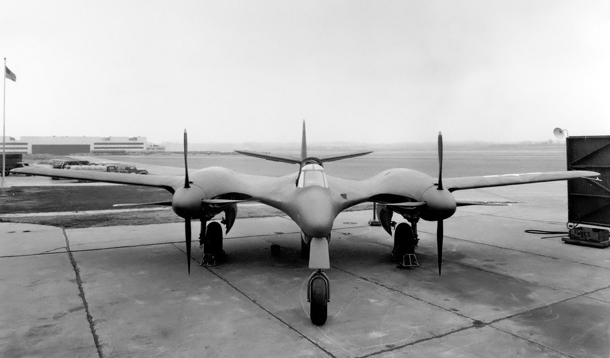
McDonnell continued to work with the AAC to refine the design of the Model 2A. On 30 September 1941, the Army Air Force (AAF—the AAC was renamed in June 1941) issued a contract to McDonnell to build two prototypes of the Model 2A interceptor pursuit fighter as the XP-67. The aircraft was assigned Materiel Experimental code MX-127. The first aircraft was scheduled to be delivered on 29 April 1943, with the second example delivered six months later on 29 October 1943. The XP-67 had a fairly conventional layout for a single-seat, twin-engine aircraft with tricycle undercarriage. What was not conventional was the extensive blending of the fuselage and engines nacelles to the aircraft’s wings to maintain true airfoil sections throughout the entire aircraft. The end result was a streamlined appearance.

The XP-67 was constructed of an aluminum frame with aluminum skin that formed a monocoque structure. All control surfaces consisted of a fabric covered aluminum frame, although aluminum skinning was later proposed for production aircraft. Effort was expended to keep the XP-67’s surface smooth and make everything flush. Initially, a door on the left side of the pressurized cockpit was to allow access. However, pressurization was dropped on the prototype, and a glazed, rearward-sliding canopy was used.

The wings had two spars, a dihedral of five degrees, and consisted of inner and outer wing sections. The outer wing section extended from the engine nacelle and was removable. Split flaps were located between the nacelle and fuselage. A small split flap existed on the outer side of the engine nacelle. The outer wing section’s trailing edge was occupied by an aileron. The ailerons drooped 15 degrees with deployment of the flaps, which had a maximum deployment of 45 degrees. However, it does not appear that the drooping ailerons were ever installed on the prototype. No hardpoints existed under the wings for bombs or drop tanks.

McDonnell-Model-2A-drawing

The Model 2A as originally proposed in May 1941 was essentially the latest Model 2 design but with large fairings that blended the fuselage and engine nacelles to the wing. This design was contracted as the XP-67.

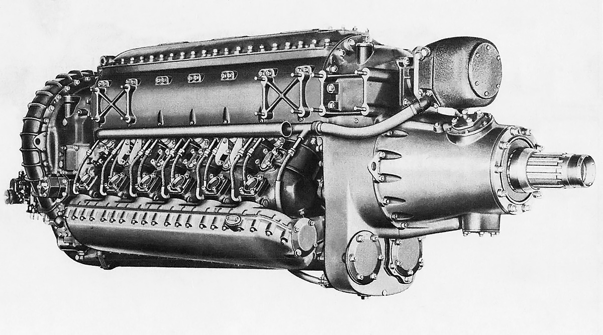
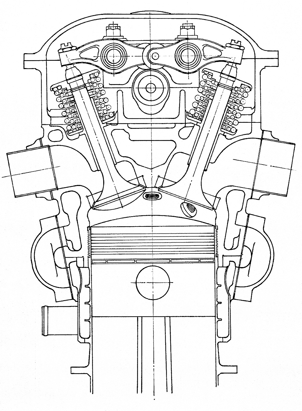
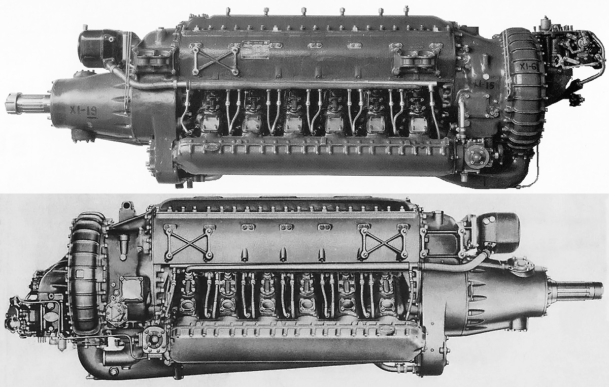
Mounted to each wing was a liquid-cooled, Continental XI-1430 inverted V-12 engine. Initially, clockwise-rotating (right-handed) XI-1430-1 engines were to be used. In June 1942, the engines were switched to an XI-1430-17 installed on the right wing (clockwise, right-handed rotation) and an XI-1430-19 installed on the left wing (counterclockwise, left-handed rotation). Each engine of the first prototype turned a cuffed, four-blade Curtiss Electric constant-speed propeller that was 10 ft 6 in (3.2 m) in diameter. However, the cuffs were installed after the first aircraft was completed. In April 1943, McDonnell proposed installing Curtiss Electric contra-rotating propellers on the second XP-67 prototype, noting that such a change would increase the aircraft’s speed by 7–10 mph (11–16 km/h) and climb rate by 400 fpm (2.0 m/s).

The engine nacelle extended back from each engine and housed a General Electric D-23 turbosupercharger. Engine exhaust was directed straight back from the nacelle to gain some thrust. Initially, it was proposed that each engine would have a coolant radiator located in the fuselage. This was changed to each engine having two coolant radiators housed in the engine nacelle and located directly under the rear of the engine. The engine nacelles were blended into the wing, and several intakes were incorporated into the wing’s leading edge. For both engine nacelles, the intakes closest to the nacelle passed air to a cooling jacket around the exhaust manifold. The center intake directed air through the two coolant radiators per engine and to the turbosupercharger. The intakes farthest from the engine each led to an oil cooler.

An oil tank in each wing held 26 gallons (98 L) for each engine. The aircraft’s normal fuel load was 282 gallons (1,067 L), but 478 gallons (1,809 L) of additional fuel could be housed in the aircraft’s four fuel tanks located in the fuselage and wing. This brought the XP-67’s total fuel capacity to 760 gallons (2,877 L). The aircraft’s tricycle landing gear was hydraulically-powered and fully retractable. The nose wheel was swiveled, but was not steerable, and folded back into the fuselage. The main gear was mounted just inboard of the engine nacelles and folded inward. In early 1942, the AAF requested that the main gear fold into the engine nacelle, necessitating a complete redesign of the nacelles to accommodate the rearward retracting main wheels. The horizontal stabilizer had 9.55 degrees of dihedral and was mid-mounted to the aircraft’s vertical stabilizer. Like the outer wing panels, the tail was detachable for transporting the aircraft by ground. The XP-67 airframe was stressed for +8 and -4 Gs and had a diving limit of 604 mph (972 km/h) indicated.

McDonnell-XP-67-nacelle-LMAL

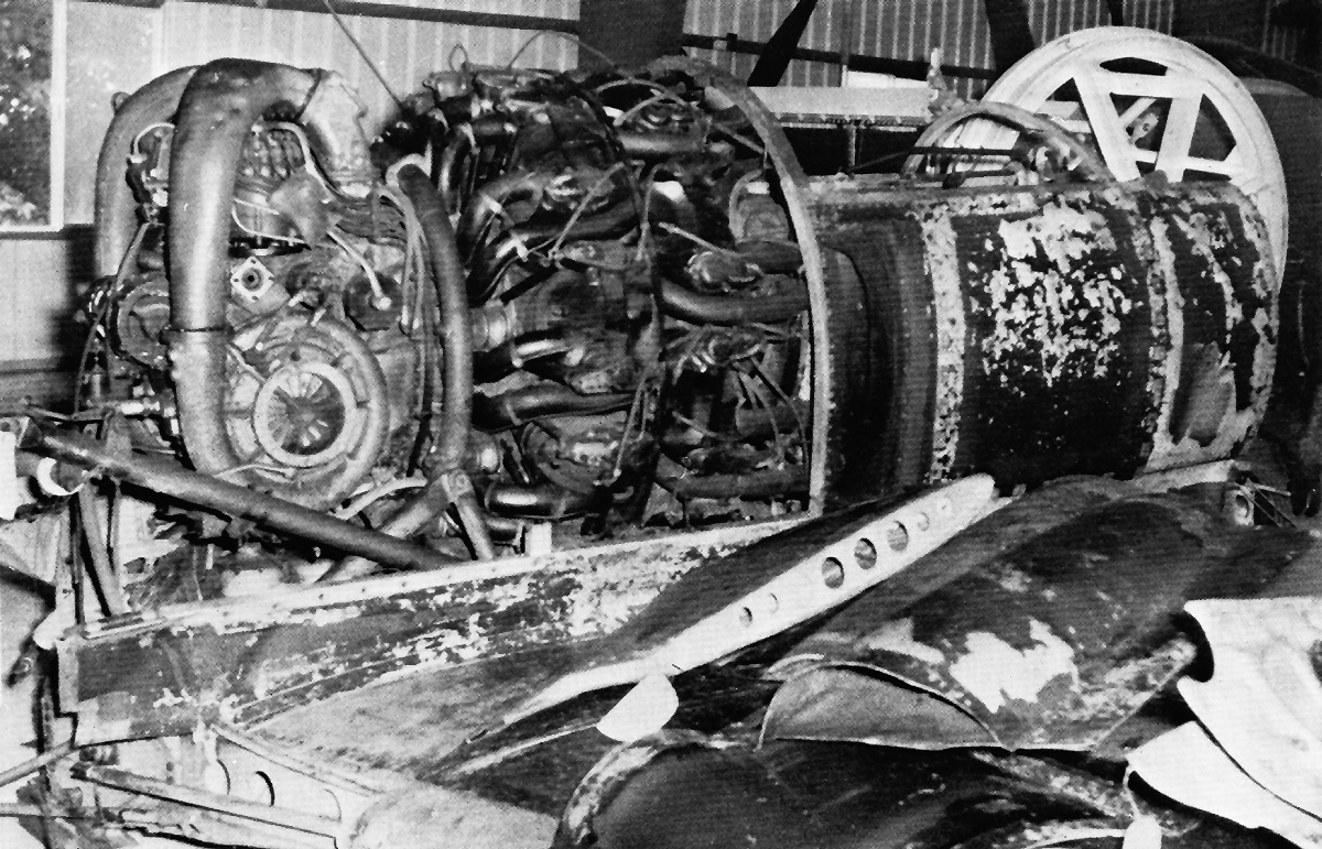
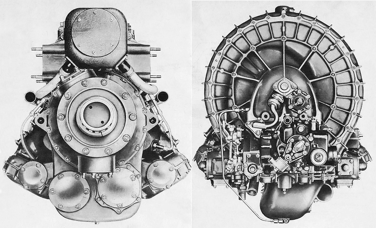
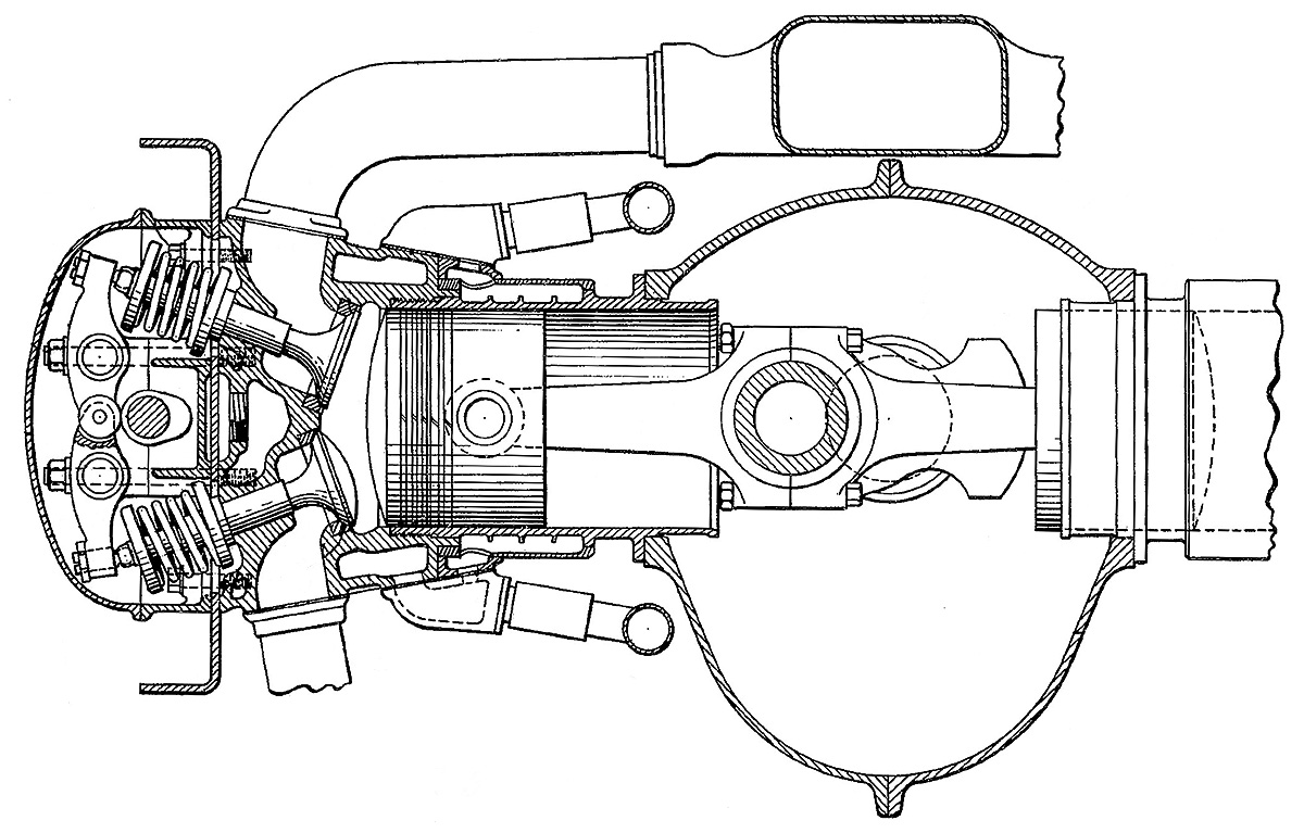
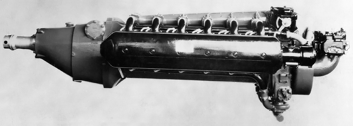
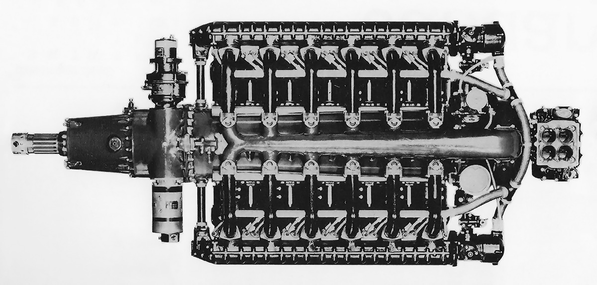
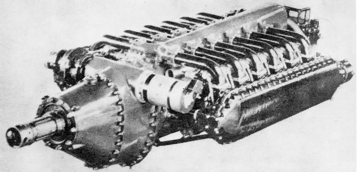
An XI-1430-17 with a GE D-23 turbosupercharger installed in the McDonnell XP-67 wing section for tests at the Langley Memorial Aeronautical Laboratory in September 1943. The tests were conducted to evaluate the cooling ducts of the XP-67’s radical blended design. The top image illustrates the unusual ducting of the XP-67’s nacelles, which were duplicated on the opposite side. Closest to the spinner is the exhaust manifold cooling air duct. The large middle duct was for the coolant radiator and engine intake. The outer duct was for the oil cooler. The bottom image shows the turbosupercharger, which was installed so that the exhaust provided additional thrust. Note the radiator cooling air exit duct on the landing gear door and the cuffed propellers. (LMAL images)

The XP-67’s armament changed as the aircraft was developed. Initially, the aircraft would have four 20 mm cannons with 166 rounds per gun and six .50-cal machine guns with 500 rounds per gun. The cannons would be installed on the sides of the cockpit, just behind the pilot. The machine guns were to be installed just behind the cannons. On 5 August 1941, the AAF requested that two 37 mm cannons be installed in place of two 20 mm cannons. By 16 August, the armament was revised again to six 37 mm cannons with 45 rounds per gun and no other guns. The 37 mm cannons were installed in the blended-wing’s leading edge between the cockpit and engine nacelle. The three cannons on each side of the fuselage were outside of the propeller arc. On 20 October, it was suggested that the aircraft’s design should incorporate provisions to replace four of the 37 mm cannons with four 20 mm cannons. On 8 November, it was decided that the first aircraft would have six 37 mm cannons, and the second aircraft would have two 37 mm and four 20 mm cannons.

Extensive wind tunnel tests were conducted on various XP-67 models throughout 1942 and 1943. These tests led to many minor changes in the aircraft. Much of this testing was focused on the extensive fairing used to blend the wing and fuselage. The cooling system was also carefully scrutinized with many minor changes taking place to the cooling ducts. A full-size mockup of the XP-67 was inspected in mid-April 1942, which led to more changes. The most significant changes were lengthening the aircraft’s nose by 15 in (381 mm) and changing the flight control actuation system from push-pull rods to cables. In May, a fuselage section was built to test fire the 37 mm cannons. The tests proved satisfactory, but McDonnell redesigned the 37 mm cannon installation in October, necessitating another mockup and more tests. The new 37mm cannon installation mockup successfully passed its tests in March 1944, but the armament was never installed in the prototype. On 17 June 1942, the decision was made to finish the prototype without a pressurized cockpit. In April 1943, there were discussions of cancelling the XP-67, but the aircraft was seen as a good way to test the experimental wing blending, cannon armament, and XI-1430 engines.

McDonnell-XP-67-construction

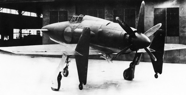
The McDonnell XP-67 nearly complete in mid-November 1943. Even though the nacelle’s duct design was found to be insufficient in the wind tunnel tests, the aircraft was not modified with a new design until later. Note the covered ports for 37 mm cannons on each side of the cockpit and that the propellers do not have their cuffs installed.

McDonnell had built a full-scale XP-67 engine nacelle for testing the XI-1430 engine installation. Tests were conducted by McDonnell starting in May 1943. After accumulating almost 27 hours of operation, the rig was sent to the National Advisory Committee for Aeronautics (NACA) at the Langley Memorial Aeronautical Laboratory (LMAL, now Langley Research Center) in Virginia. The NACA added about 17.5 hours to the engine conducting tests in August and September to analyze the installation’s effectiveness for cooling the coolant, oil, and intercooler. The tests indicated that the cooling system was insufficient. The nacelle with revised ducts was then shipped to Wright Field in Dayton, Ohio in October 1943. Wright field added another 6.5 hours to the engine, bringing the total to 51 hours. The new ducts proved satisfactory, reducing the drag of the ducts by 25 percent and improving cooling by 200 percent. However, excessive vibrations occurred between the engine and its mounting structure, necessitating a more rigid mount. McDonnell was allowed to proceeded with testing the first XP-67, although the prototype would not be changed until after its first flight when additional changes beyond the cooling system would most likely need to take place. Wind tunnel tests had indicated that the horizontal stabilizer would need to be raised by 12 in (305 mm) to improve stability. McDonnell was instructed to stop work on the second prototype until successful flight tests of the first aircraft had been conducted.

Serial number 42-11677 was given to the first XP-67, and serial number 42-11678 was given to the second prototype. Unofficially, the XP-67 was given the name ‘Moonbat’ or just ‘Bat,’ but it does not appear that an official name was ever bestowed upon the aircraft. With all the design changes since the XP-67 was initially contracted, the aircraft’s specifications had changed. The wingspan remained at 55 ft (16.8 m), but the length increased 2 ft 6 in (.8 m) to 44 ft 9 in (13.6 m), and the height increased 1 ft (.3 m) to 15 ft 9 in (4.8 m). The standard fuel load remained at 280 gallons (1,060 L), but the additional fuel load decreased by 25 gallons (95 L) to 455 gallons (1,722 L), giving a total maximum internal fuel load of 735 gallons (2,782 L). The XP-67’s weight had increased by 3,792 lb (1,720 kg), resulting in an empty weight of 17,745 lb (8,049 kg), a gross weight of 22,114 lb (10,031 kg), and a maximum weight of 24,836 lb (11,265 kg). A reduction in performance accompanied the weight increase, resulting in an estimated speed of 448 mph (720 km/h) at 25,000 ft (7,620 m), which was a 24 mph (39 km/h) reduction, and 367 mph (591 km/h) at sea level. The time to climb to 25,000 ft (7,620 m) was increased by nearly five minutes to 14.8 minutes, and the service ceiling decreased 4,100 ft (1,250 m) to 37,400 ft (11,400 m). The XP-67’s cruising speed decreased 46 mph (74 km/h) to 270 mph (435 km/h), but maximum range was little changed at 2,385 miles (3,838 km) with 735 gallons (2,782 L) of fuel.

McDonnell-XP-67-right-front

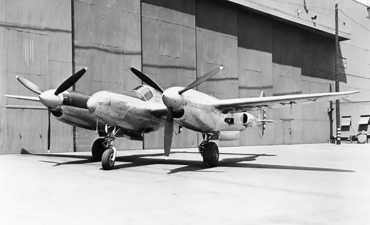
The completed XP-67 with revised nacelle cooling ducts and after the horizontal stabilizer was raised 12 in (305 mm). The most noticeable duct modification was to the exhaust manifold cooling intake, which was changed to a scoop. Note that the propellers rotated in opposite directions.

On 1 December 1943, the XP-67 had its XI-1430 engines installed and was ready for ground tests. However, both engines caught fire and damaged the aircraft on 8 December. The fires were caused by issues with the exhaust manifolds. The XP-67 was repaired and made its first flight on 6 January 1944, taking off from Scott Field in Belleville, Illinois. The flight was nearly two years later than the anticipated first flight when the XP-67 contract was originally issued. Test pilot Ed E. Elliott had to cut the flight to just six minutes due to both turbosuperchargers overheating, which resulted in small fires. During the short flight, the XP-67 exhibited good handling characteristics.

The aircraft was again repaired, with the second and third flights occurring on 26 and 28 January 1944. On 1 February, the aircraft’s fourth flight was cut short due to a main bearing failure on the left engine caused by an unintentional overspeed of the engine. The cockpit canopy also detached during the flight. While the XP-67 was down for repairs and new XI-1430 engines, the horizontal stabilizer was raised 12 in (305 mm). The cooling ducts in the engine nacelles were also modified, with the most noticeable being the exhaust shroud inlet, which was changed to more of a scoop. The updated aircraft flew again on 23 March 1944 and demonstrated improved stability, but one turbosupercharger failed at 10,000 ft (3,048 m).

In April 1944, it was reported that the engines were running too cool. The closed main gear door formed part of the air duct aft of the radiator. However, the gear doors did not seal tightly and caused an excessive amount of air to exit the duct. This resulted in too much air passing through the radiator and reducing the engine temperature below ideal levels. McDonnell was allowed to install a thermostat on the prototype to help control coolant temperatures but was also told that such issues would not be acceptable on production aircraft. Around this same time, construction of the second prototype was allowed to proceed with the exception of parts that would be affected by an engine change.

McDonnell-XP-67-top

The unusual planform of the XP-67 is illustrated in this view. The two ports in the middle of each nacelle were the forward exit for the exhaust manifold cooling air. The rear exit is denoted by the white staining at the end of the nacelle. The outer wing section was detachable just outside of the nacelle.

In May 1944, three AAF pilots flew the XP-67 and reported that the XI-1430 engines ran rough and seemed underpowered. Tests indicated that at normal power, the engines were only delivering 1,060 hp (790 kW), well below the expected 1,350 hp (1,007 kW). The XP-67 was noted for having high control forces at high speeds, exhibiting a Dutch roll indicating some directional instability, and not making a good gun platform. The maximum speed with the engines delivering 1,600 hp (1,193 kW) at 3,200 rpm was 357 mph (574 km/h) at 10,000 ft (3,048 m) and 393 mph (632 km/h) at 20,000 ft (6,096 m). From these values and other tests, McDonnell calculated that the XP-67 could attain 405 mph (652 km/h) at 25,000 ft (7,620 m) at the same power setting. Takeoff speed was 130 mph (209 km/h); the clean stall speed was 118 mph (190 km/h) with buffeting starting at 140 mph (225 km/h); and the aircraft had a high landing speed of 120 mph (193 km/h). In general, the XP-67 was found to be inferior to other fighters currently in production.

McDonnell got permission to install contra-rotating propellers on the first prototype when the engines were ready, and they were expected in June 1944. No information has been found indicating that the contra-rotating versions of the XI-1430 were delivered. In June, it was decided to install 11 ft (3.4 m) diameter four-blade Aeroproducts propellers rather than contra-rotating propellers. However, tests would continue with the Curtiss propellers until the Aeroproducts were ready. It was also noted that the XP-67 had experienced no engine fires since its fourth flight, and the aircraft had completed about 50 flights without any serious issues.

McDonnell-XP-67-in-flight

The limited flight trials of the XP-67 indicated the aircraft handled fairly well. It was noted as underpowered and slightly unstable. Overall, visibility was said to be poor, with the engine and fairing blocking most of the view to the side and rear. Formation flying would have been difficult, as the pilot was unable to see their wingtips.

In July 1944, some in the AAF felt that the XP-67 program was expensive and served no purpose. However, others felt that the aircraft was a unique platform that would allow the testing of the six 37 mm cannons. In addition, the possibility existed to install 12 .50-cal machine guns or eight 20 mm cannons. The aircraft was seen as a good test machine, even if its performance fell below what was originally specified. It was decided to complete tests on the current aircraft to assess the blended design and then consider the possibility of armament trials.

McDonnell had long sought to change the aircraft’s engines. On 19 January 1944, McDonnell proposed discarding the XI-1430s for the second prototype and using either two-stage Allison V-1710 or Rolls-Royce Merlin RM 14SM (100-series prototype) piston engines. In addition, each engine nacelle would house a Westinghouse 9.5 (J32) turbojet behind the piston engine. The mixed-power proposal was brought up again on 16 March 1944, now using an Allison V-1710-199 (F32R) piston engine and either a Rolls-Royce W2B/37 turbojet or a GE I-20 (J39) turbojet in the nacelle. With mixed power plants, the aircraft had an estimated top speed at sea level of 500 mph (805 km/h). The engine issue was discussed again in July 1944, with McDonnell now suggesting a Rolls-Royce Merlin RM 14SM piston engine paired with a GE I-20 (J39) turbojet in each nacelle. However, AAF felt that the aircraft would need a complete redesign to incorporate different piston engines with turbojets.

Since its initial design in May 1941, there were suggestions of using a modified version of the XP-67 for photo reconnaissance. In April 1942, McDonnell suggested that the aircraft’s range could be extended to 4,000 miles (6,437 km) at a cruise speed of 200 mph (322 km/h), which would be a 20-hour flight. For this, two of the 37 mm cannons would need to be omitted and six additional fuel tanks installed along with 280 lb (127 kg) of ballast in the nose. With the extra tanks, the aircraft’s internal fuel capacity was 1,290 gallons (4,883 L). This concept was not pursued at the time, but the range extension was considered later for a photo-recon role.

McDonnell-XP-67E-model

A model of the XP-67E with its bubble canopy and mixed piston / turbojet power plants. It is not clear what engines (if any) are intended to be depicted by the model, but the nacelles were extended back to house the jet engine (LMAL image).

By July 1944, it was believed that a photo-recon version of the XP-67 would have inferior performance compared to the Lockheed F-5 (P-38). However, a mixed-power version of the aircraft was seen as a possible candidate as a photo-recon aircraft. The XP-67E was designed for the photo-recon role, and it incorporated mixed power, additional internal fuel tanks, and provisions for two 150-gallon (568-L) drop tanks mounted under the aircraft’s center section. In the XP-67E design, the engine nacelles were extended back to house the GE I-20 (J39) turbojet engine. Cameras were installed in the aft fuselage, and the XP-67E was unarmed. The fuselage was mostly unchanged, but the cockpit was enclosed in a rearward-sliding bubble canopy.

The XP-67 prototype had been undergoing modifications and repairs through August 1944. Perhaps the most major change was alerting the wing dihedral from 5 degrees to 7 degrees in an attempt to increase stability. The aircraft was ready to resume flight tests in early September. On 6 September 1944, the exhaust valve rocker of the No. 1 cylinder in the XP-67’s right engine broke while the aircraft was in flight at 10,000 ft (3,048 m). Exhaust gases unable to escape the cylinder backed up into the intake manifold and caused it to fail, resulting in a fire. The fire was first noticed at 3,000 ft (914 m) as the aircraft was preparing to land. Test pilot Elliott was able to land the XP-67 and stopped it to limit the flames from spreading. However, the brake failed after Elliott exited the aircraft, and wind turned the XP-67 so that the flames blew toward the fuselage. The XP-67 was nearly burned in half and damaged beyond repair. The aircraft had a total flight time of 43 hours. This event effectively killed the XP-67 project and the XP-67E photo-recon proposal. The entire program was suspended seven days later on 13 September, and on 24 October, McDonnell was notified that the XP-67 contract was cancelled. A formal Notice of Cancellation followed on 27 October 1944. The second prototype was about 15 percent complete and was subsequently scrapped. The total cost of the XP-67 program was approximately $4,733,476.92.

McDonnell-XP-67-fire-front

The XP-67 after the fire on 6 September 1944. Once on the ground, the fire from the right engine spread to the rear fuselage and left nacelle. The rear fuselage was nearly burned through and collapsed to the ground. An inglorious end to both the XP-67 and XI-1430 programs.

Sources:
Interceptor Pursuit Airplane Twin Engine Type XP Preliminary Specifications by McDonnell Aircraft Corporation (5 May 1941)
Memorandum Report on XP-67 Airplane, AAF No, 42-11677 by Osmond J. Ritland (19 May 1944)
Final Report on the XP-67 Airplane by John F Aldridge Jr. (31 January 1946)
Case History of XP-67 Airplane by Historical Division, Air Materiel Command (23 July 1946)
USAF Fighters of World War Two Volume Three by Michael O’Leary (1986)
U.S. Experimental & Prototype Aircraft Projects: Fighters 1939-1945 by Bill Norton (2008)

Continental-XI-1430-right-front

Continental XI-1430 Aircraft Engine

By William Pearce

In 1932, the Army Air Corps (AAC) contracted the Continental Motors Company to develop a high-performance (Hyper) cylinder that would produce 1 hp per cu in (.7 kW per 16 cc). Based on promising test results, an order was placed for a 1,000 hp (746 kW), 12-cylinder O-1430 aircraft engine. The AAC had stipulated that the engine needed to be a horizontally opposed (flat) configuration and use individual cylinders. Lengthy delays were encountered with development of the Hyper No. 2 cylinder, and the situation was made worse by Continental’s financial state. Continental did not fund much of the project, and each change and every purchase was sent to the AAC for contractual approval.

Continental-XI-1430-right-front

The Continental XI-1430 was a compact, high-performance aircraft engine capable of producing an impressive amount of power but also suffered from reliability issues. The mounting pads on the front accessory case, below the nose case, were for the starter and generator.

The O-1430 was finally completed and run in 1938. While it did meet the 1,000 hp (746 kW) goal, the six years of development rendered the engine obsolete. The Allison V-1710 and the Rolls-Royce Merlin had already passed the 1,000 hp (746 kW) mark years previously. However, the AAC and Continental believed that the engine could be reworked to produce 1,600 hp (1,193 kW). In 1939, the AAC requested that Continental use the O-1430 as the basis for an inverted Vee engine designated XI-1430. Especially early on, the engine was also referred to as the XIV-1430 or IV-1430. The XI-1430 would keep the basic individual cylinders of the O-1430, but the cooling requirement was changed from 300° F (149° C) to 250° F (121° C). The Vee configuration (even if inverted) and 250° F (121° C) coolant were preferred by Continental from the start. To speed development of the engine, Continental agreed to put at least $250,000 of its own money toward the project and was willing to proceed based on verbal agreements with the AAC rather than waiting for changes to be specified in writing.

In 1940, Continental Motors Company created a subsidiary known as Continental Aviation and Engineering Corporation to develop aircraft engines of over 500 hp (373 kW). Most of the XI-1430 development was done under the Continental Aviation and Engineering Corporation. The XI-1430 was essentially a new engine with perhaps just the pistons, connecting rods, and a few other parts being interchangeable with the earlier O-1430.

The XI-1430 had a one-piece aluminum crankcase. The crankshaft was supported by seven main bearings and secured to the crankcase by bearing caps. A cover plate sealed the top of the inverted crankcase. Two banks of six individual cylinders were secured to the crankcase via studs. The cylinder banks had an included angle of 60 degrees. The pistons were attached to the crankshaft via fork-and-blade connecting rods. When viewed from the rear, the blade rods served the left bank, and the fork rods served the right bank.

Continental-XI-1430-9-clockwise-geartrain

The gear train of a clockwise-turning (right-handed) XI-1430-9. Unlike with the O-1430 in which a few gears could be swapped for clockwise vs counterclockwise rotation, the XI-1430 had a different gear train that incorporated various idler gears for counterclockwise rotation.

The cylinders used the same bore and stroke as the Hyper No. 2 test cylinder and the O-1430. While their design was similar to the previous applications, the XI-1430’s cylinders had been further refined. Each cylinder was made up of a forged steel barrel screwed and shrunk into a forged aluminum cylinder head. The new cylinder head was more compact than that used previously. A steel water jacket surrounded the cylinder barrel and was secured to the cylinder head. Two spark plugs were installed in each cylinder, with one by the intake port and the other by the exhaust port. The cylinder had a single intake valve and a single sodium-cooled exhaust valve. Both valves were actuated by a single overhead camshaft located in a housing that bolted atop all the cylinders of a given bank. Each camshaft was driven through bevel gears by a nearly-horizontal shaft at the front of the engine. Various accessories were driven from the rear of the camshaft.

An updraft Stromberg injection carburetor was positioned at the extreme rear of the XI-1430 engine. It fed air and fuel into the single-speed, single-stage supercharger, which was mounted to the rear of the engine. The supercharger impeller was 10.5 in (267 mm) in diameter and turned at 5.928 times crankshaft speed. The supercharger drive case also powered various pumps: oil, water, vacuum, and hydraulic. An intake manifold led from the bottom of the supercharger and extended through the inverted Vee of the engine. Short individual runners branched off the manifold and supplied the air and fuel mixture to each cylinder.

An accessory drive case was mounted to the front of the engine. Driven from the accessory case were the starter, generator, an oil pump, and a single dual-magneto. The magneto was mounted on the upper front of the accessory drive case and fired the two spark plugs in each cylinder. The accessory drive case also housed the spur gears that made up part of the XI-1430’s propeller gear reduction. Mounted to the front of the accessory drive was a nose case that contained a bevel planetary gear reduction that drove the propeller shaft. The speed of the crankshaft was partly reduced via the spur gears in the accessory drive case, then further reduced via the planetary gears in the nose case. This two-stage gear reduction was probably adopted to keep the XI-1430’s frontal area to a minimum and possibly to extended the nose of the engine for a more streamlined installation. Depending on the engine model, the final speed of the propeller shaft was .360, .385, or .439 crankshaft speed.

Continental-XI-1430-front-and-rear

Front and rear views of the XI-1430 illustrate the engine’s rather compact configuration. On the front of the engine, the housings for the camshaft drives can just be seen between the accessory drive and the circular covers on the cylinder banks. Note the size of the supercharger housing on the rear view.

The Continental XI-1430 had a 5.5 in (140 mm) bore and a 5.0 in (127 mm) stroke. The engine displaced 1,425 cu in (23.4 L) and had a compression ratio of 6.5 to 1. XI-1430 installations included a General Electric (GE) turbosupercharger and air-to-air intercooler. The engine initially had a takeoff rating of 1,350 hp (1,007 kW) at 3,300 rpm and a military rating of 1,600 hp (1,193 kW) at 3,200 rpm up to 25,000 ft (7,620 m). Development ultimately increased takeoff power to 1,600 hp (1,193 kW) at 3,300 rpm and 15.3 psi (1.05 bar) of boost. The XI-1430 maintained this power as its normal rating up to 25,000 ft (7,620 m), but at 3,000 rpm. Emergency power was 2,100 hp (1,566 kW) at 3,400 rpm with 28.5 psi (1.97 bar) of boost at 25,000 ft (7,620 m). The XI-1430 was 112.5 in (2.86 m) long, 30.9 in (.78 m) wide, and 33.5 in (.85 m) tall. The engine weighed 1,615 lb (733 kg).

On 20 February 1940, the AAC issued Request for Data R40-C that sought designs of new fighter aircraft capable of 450 mph (724 km/h), with 525 mph (845 km/h) listed as desirable. With a new generation of high-power aircraft engines under development, manufacturers saw it as an opportunity be creative. Five of the 26 submitted designs (some of which only offered slight variations) used the XI-1430 as the selected engine. Bell offered two XI-1430-powered variants of what was similar to a P-39 Airacobra, and two Curtiss-Wright XI-1430-powered submissions were similar to reengined examples of their CW-21 and XP-46. The later design was contracted mid-1940 as the XP-53. However, due to delays with the XI-1430 engine, the AAC requested the substitution of a Packard V-1650 (Merlin) in October 1940, and the XP-53 was subsequently redesignated as the XP-60.

A third XI-1430-powered R40-C proposal from Curtiss-Wright was a pusher aircraft designated P-249C. A design contract for the P-249C was issued on 22 June 1940, but the decision was made not to proceed with a prototype. Curtiss-Wright continued to refine the design and substituted an Allison V-1710 engine (this aircraft design was also an R40-C submission). The V-1710-powered aircraft was eventually built as the XP-55 Ascender. None of XI-1430-powered R40-C aircraft were built.

Continental-XI-1430-left-rear

The induction pipe can be seen extended from the bottom of the supercharger housing and to the inverted Vee between the cylinder banks. Note how the camshaft housing was attached to each individual cylinder.

In March 1940, the engines for the Lockheed XP-49 design were switched to the XI-1430 with a GE B-33 turbosupercharger. The XP-49 was not part of R40-C and was essentially an advancement of the P-38 Lightning. The Pratt & Whitney X-1800 / XH-2600 originally selected for the XP-49 was cancelled, necessitating a power plant switch. Lockheed began to modify the XP-49 for the XI-1430 engines.

In mid-1940, the AAC expressed interest in the XI-1430-powered Bell XP-52. The XP-52 was a twin-boom pusher fighter that never progressed beyond the initial design phase. The project ended in October 1940, before a contract was formalized.

For R40-C, McDonnell Aircraft Corporation proposed four variants of its Model 1 with different engines. None of the variants used the IX-1430. The Model 1 had its engine buried in the fuselage and drove wing-mounted pusher propellers via extensions shafts and right-angle gear boxes. Although radical, the AAC purchased engineering data and a wind tunnel model of the design. McDonnell worked with the AAC to refine the design, which eventually became the Model 2a. The Model 2a was powered by two XI-1430 engines, each with a GE D-23 turbosupercharger. On 30 September 1941, the Army Air Force (AAF—the AAC was renamed in June 1941) contracted McDonnell to build two prototypes of the aircraft as the XP-67.

Meanwhile, the XI-1430 was first run in late 1940 and underwent its first tests in January 1941. Plans were initiated to install the XI-1430 in a few P-39D aircraft, but the concept was ultimately dropped due to a lack of available engines. In July 1941, the AAF and the Defense Plant Corporation funded a new aircraft engine plant for Continental on Getty Street in Muskegon, Michigan that cost $5 million. It appeared as if the AAF truly believed that the XI-1430 would be a successful engine.

Continental-XI-1430-XP-49

The Lockheed XP-49 was obviously a development of the P-38, with the airframes sharing many common parts. However, the XP-49 as built offered no advantage over the P-38, and the aircraft was used mostly as an XI-1430 test bed.

On 22 April 1942, XI-1430 engines that were not fully developed were delivered to Lockheed in Burbank, California for installation in the XP-49. In May, the engine passed a preliminary test at 1,600 hp (1,193 kW). The XP-49 made its first flight on 11 November 1942, piloted by Joe Towle. That same month, the AAF ordered 100 I-1430 engines but required a type test to be passed before delivery. At the end of November, the XP-49 had more powerful engines installed capable of 1,350 hp (1,006 kW) for takeoff and 1,600 hp (1,193 kW) at 25,000 ft (7,620 m). The engines in the XP-49 proved to be troublesome and required constant maintenance, and the aircraft itself had numerous issues. The I-1430 was also having trouble passing the type test. Around August 1943, the AAF cut its order to 50 engines and later reduced the quantity again to 25. By September 1943, the XP-49 became essentially a testbed for the XI-1430, as the aircraft offered no advantage over the P-38. It was clear that the XP-49 would not go into production.

McDonnell had built a full-scale XP-67 engine nacelle for testing the XI-1430 engine installation. Tests were conducted by McDonnell starting in May 1943. After accumulating almost 27 hours of operation, the rig was sent to the National Advisory Committee for Aeronautics (NACA) at the Langley Memorial Aeronautical Laboratory (now Langley Research Center) in Virginia. The NACA added about 17.5 hours to the engine conducting tests to analyze the installation’s effectiveness for cooling the coolant, oil, and intercooler. The tests indicated that the cooling was insufficient. The nacelle with revised ducts was then shipped to Wright Field in Dayton, Ohio in October 1943. Wright field added another 6.5 hours to the engine, bringing the total to 51 hours. The new ducts proved satisfactory, and McDonnell was allowed to proceeded with XP-67 testing. However, excessive vibrations were noted between the engine and its mounting structure, and a more rigid mount was required to resolve the issue.

On 1 December 1943, the XP-67 had its XI-1430 engines installed and was ready for ground tests. However, both engines caught fire and damaged the aircraft on 8 December. The fire was caused by issues with the exhaust manifolds. By the end of 1943, the AAF had reduced the I-1430 order to just eight engines, signaling that the engine would not enter quantity production. The XP-67 was repaired and made its first flight on 6 January 1944, taking off from Scott Field in Belleville, Illinois. Test pilot Ed E. Elliott had to cut the flight to just six minutes due to both turbosuperchargers overheating, which resulted in small fires. The aircraft was again repaired, but engine and turbosupercharger issues continued to plague the program. The engines were only delivering 1,060 hp (790 kW), well below the expected output of 1,350 hp (1,007 kW).

Continental-XI-1430-underside-XP-67

Underside of an XI-1430-17 installed in the McDonnell XP-67 wing section for tests at the Langley Memorial Aeronautical Laboratory in September 1943. The tests were conducted to evaluate the cooling ducts of the XP-67’s radical blended design. Illustrated is the engine’s intake manifold and two coolant radiators. Note the generator and starter installed on the front accessory drive. The air-cooled jackets surrounding the engine’s exhaust manifolds are also visible. (LMAL image)

In March 1944, the I-1430 type test was partially completed, and the eight engines ordered by the AAF were delivered. At the time, the engine achieved an emergency power rating of 2,000 hp (1,491 kW) with water injection. Continental continued its efforts, and in August 1944, the I-1430 earned a rating of 2,100 hp (1,566 kW) with 150 PN fuel and no water injection.

On 6 September 1944, the exhaust valve rocker of the No. 1 cylinder in the XP-67’s right engine broke while the aircraft was in flight. Exhaust gases unable to escape the cylinder backed up into the induction manifold and caused it to fail, resulting in a fire. Test pilot Elliott was able to land the aircraft, but it was subsequently damaged beyond repair by the fire. This event effectively killed the XP-67, and the project was suspended seven days later on 13 September. All XI-1430 development was halted around this time.

The XP-49 had continued to fly when it could, but engine and airframe issues caused the aircraft to be grounded in December 1944. No longer of any useful service, the XP-49 was subsequently scrapped.

Continental-XI-1430-XP-67

The XP-67 had an impressive appearance with its nacelles and fuselage blended into the wings. However, the XI-1430 engines did not deliver their expected power, and the XP-67’s top speed was 405 mph (652 km/h), well below the expected 448 mph (721 km/h). The XP-67 originally had a guaranteed speed of 472 mph (760 km/h) at 25,000 ft (7,620 m) with a gross weight of 18,600 lb (8,437 kg). Once its weight had increased to 22,500 lb (10,206 kg), the expected speed was reduced to 448 mph (721 km/h).

Continental had investigated designs for XI-1430 engines with a two-speed supercharger, a two-stage and two-speed supercharger, contra-rotating propellers, a spur-gear-only propeller reduction, and turbocompounding with a turbine feeding power back to the crankshaft. Continental was to supply XI-1430 engines with a contra-rotating propeller shaft for the second XP-67. The engines were expected in June 1944, but no further information has been found.

Continental did work with General Electric on a turbocompound XI-1430 in 1943, and it appears detailed design work was undertaken. The XP-67 was used for performance calculations with a turbocompounded XI-1430 engine. The turbocompound engines decreased the time of a climb to 25,000 ft (7,620 m) by approximately 38 percent and increased range by 25 percent. The turbocompound XI-1430’s output was an additional 580 hp (395 kW). The engine with its power recovery turbine weighed an additional 235 lb (107 kg), but the total installation weight was only 30 lb (14 kg) additional because a turbosupercharger and its ducting was not needed. In February 1944, Materiel Command’s Engineering Division encouraged the completion of a turbocompound XI-1430 engine to test against the calculated performance estimates, but it does not appear that a complete engine was ever built.

Although the XI-1430 was lighter and more powerful than comparatively sized engines in production, it required additional development to become reliable. It was obvious that the engine would not see combat in World War II, and there was little point in continuing the program. A total of 23 XI-1430 engines were built, and at least six engines are known to survive. A -11 and a -15, are held by the Smithsonian Air and Space Museum, a -9 is on display at the National Museum of the U.S. Air Force, a running -11 is part of a private collection, and two other unrestored engines are part of another private collection.

Continental-XI-1430-left-right-NASM

The two XI-1430 engines held by the Smithsonian Air and Space Museum, with the -11 at top and the -15 at bottom. Both examples rotate counterclockwise (left-handed). The engines are currently in storage and not on display. (NASM images)

Sources:
Development of Aircraft Engines and Aviation Fuels by Robert Schlaifer and S. D. Heron (1950)
Continental! Its Motors and its People by William Wagner (1983)
Aircraft Engines of the World 1946 by Paul H. Wilkinson (1946)
Service Instructions for Aircraft Engines Army Models I-1430-9 and -11 By (20 May 1943)
Performance of the McDonnell XP-67 Airplane with XI-1430 Compound Engines and with Present XI-1430 Engines Using Continental Turbo Chargers by J. H. Gilmore, E. P. Kiefer, and H. D. Delameter (25 February 1944)
U.S. Experimental & Prototype Aircraft Projects: Fighters 1939-1945 by Bill Norton (2008)
American Secret Pusher Fighters of World War II by Gerald H. Balzer (2008)
Final Report on the XP-67 Airplane by John F. Aldridge, Jr. (31 January 1946)
Tornado: Wright Aero’s Last Liquid-Cooled Piston Engine by Kimble D. McCutcheon (2001)
– “Fabricated Crankcase Structure” U.S. patent 2,340,885 by James W. Kinnucan (filed 7 December 1940)
– “Cylinder Head” U.S. patent 2,395,712 by Carl F. Bachle (filed 12 January 1942)
– Accessory Mechanism and Drive for Aircraft Engines” U.S. patent 2,410,167 by James W. Kinnucan (filed 20 March 1942)
http://www.enginehistory.org/Collections/IV-1430/iv-1430.shtml
https://airandspace.si.edu/collection-objects/continental-hyper-i-1430-11-inverted-v-12-engine
https://airandspace.si.edu/collection-objects/continental-hyper-xi-1430-15-inverted-v-12-engine

Continental-O-1430-engine

Continental Hyper Cylinder and the O-1430 Aircraft Engine

By William Pearce

In the late 1920s, British engine expert Harry R. Ricardo hypothesized that the spark-ignition internal combustion engine with poppet valves had reached its specific power-producing zenith. The foundation for this belief was rooted in the fuel quality and technology employed at the time. Ricardo recommended that a single sleeve valve should replace the cylinder’s poppet valves and would enable the continued increase of an engine’s specific power output.

Continental-Hyper-Cylinder-No-2-sectional

Sectional drawing of the Continental Hyper No. 2 cylinder from August 1933. The domed exhaust valve is on the left. The domed piston had recesses to provide clearance for the valves.

British expatriate turned American citizen Sam D. Heron was also an engine expert and was employed at the time by the Army Air Corps (AAC) at Wright Field in Dayton, Ohio. Heron was involved in engine research, and with the approval of the AAC, he began to explore the power limits of the spark-ignition internal combustion cylinder with poppet valves. However, Heron had access to one thing that Ricardo did not consider: sodium-cooled exhaust valves.

Around 1923, Heron had developed an air-cooled cylinder for use on the Liberty V-12 engine. This cylinder had a 4.625 in (117 mm) bore, a 7.0 in (178 mm) stroke, and displaced 117.6 cu in (1.93 L). Around 1925, Heron developed the sodium-cooled exhaust valve. These valves had a hollow stem that was partially (approximately 2/3) filled with sodium. Once the valve reached 208° F (98° C), the sodium melted. The up-and-down movement of the valve sloshed the sodium in the valve. The sodium absorbed heat from the valve head, cooling it, and transferred the heat to the valve stem. The valve stem extended out of the cylinder and transferred the heat to the valve guide boss and subsequently to the cooling fins (if air cooled) or the water jacket (if water-cooled). The exhaust valve was a hot spot inside the cylinder that could cause detonation. Detonation is the spontaneous combustion of the remaining air and fuel mixture inside the cylinder prior to the flame front propagating from the spark plug, after it has fired, reaches that part of the cylinder. The sodium-cooled valve reduced the valve’s temperature, helping to prevent the possibility of detonation, and enabled the cylinder to produce more power.

Around 1930, Heron took the air-cooled Liberty cylinder with a sodium-cooled exhaust valve and converted it to water-cooling by adding a water jacket around the cylinder barrel. The cylinder was used on a single-cylinder test engine and quickly produced more power than the poppet valve limits described by Ricardo. At the time, an average aircraft engine cylinder produced a mean effective pressure (mep) of around 150 psi (10.3 bar). Using a single sleeve valve engine, Ricardo was able to achieve an mep of 450 psi (31.0 bar). Heron’s test cylinder was able to achieve an mep of 360 psi (24.8 bar) on its first run. Heron’s test cylinder was reworked, and an mep of 500 psi (34.5 bar) was ultimately recorded.

Continental-Hyper-Cylinder-No-2-side-bottom

Two views of the same Hyper No. 2 cylinder after its 49-hour test run in August 1933. The exhaust port is on the same side as the coolant pipe.

Encouraged by Heron’s test results, the AAC sought to develop a high-performance (Hyper) cylinder to be used on an aircraft engine. The cylinder kept the 4.625 in (117 mm) bore, but the stroke was reduced to 5.0 in (127 mm) to permit an engine speed of up to 3,400 rpm. With the change, the cylinder displaced 84.0 cu in (1.38 L). A proposed V-12 engine would incorporate 12 Hyper cylinders for a total displacement of 1,008 cu in (16.5 L) and a goal of producing 1,000 hp (746 kW). The AAC also desired a pressurized cooling system that ran straight ethylene glycol at 300° F (149° C). The then-current practice was to use normal water as the coolant, which limited the temperature to around 180° F (82° C). The high temperature was selected in an effort to decrease the size of the radiator needed in the aircraft. For proper cooling of a complete engine with the desired 300° F (149° C) coolant temperature, the AAC believed that individual cylinder construction would be required rather than six-cylinders together in a monobloc. However, an engine constructed with individual cylinders is less rigid than using monobloc construction, making the crankcase and cylinders prone to cracking when the engine is highly stressed. Individual cylinder construction also makes the engine heavier and longer, which increases torsional stresses on the crankshaft.

On 5 October 1932, a contract to develop the Hyper cylinder and design a complete 12-cylinder engine was issued to the Continental Motors Company. At the time, Continental built engines for a number of different automotive manufacturers and built medium-size air-cooled radial engines under their own name. Continental had also been contracted for experimental work on single sleeve valve engines by both the AAC and the US Navy.

Continental set up an office in Dayton, Ohio to work with Heron and the AAC regarding the design of the first test cylinder, Hyper No. 1. Continental built Hyper No. 1 to the AAC’s specifications at their main facility in Detroit, Michigan. Hyper No. 1 was constructed of a forged steel cylinder barrel screwed and shrunk into a cast aluminum head. A separate steel water-jacket was shrunk over the barrel and a shoulder of the head. The cylinder had a hemispherical combustion chamber with a single intake and a single sodium-cooled exhaust valve. The valves were actuated by an overhead camshaft via rockers. The rockers had a roller that rode on the camshaft and a pad that contacted the valve stem. Hyper No. 1 was first tested in early 1933 and soon produced 84 hp (63 kW) at 3,000 rpm, achieving the goal of producing 1 hp per cu in (.7 kW per 16 cc). However, there was some concern that a 1,008 cu in (16.5 L) engine producing 1,000 hp (746 kW) would be highly stressed, resulting in decreased reliability.

Continental-O-1430-drawing-1933

A drawing of the O-1430 included in U.S. patent 2,016,693 from October 1933 shows the engine’s basic layout. The cylinder appears to be nearly identical to that of Hyper No. 2, and the engine’s configuration matches what was ultimately built in 1938.

The AAC allowed Continental to develop a larger cylinder bore, resulting in Hyper No. 2. Hyper No. 2 had the bore increased by .875 in (22 mm) to 5.5 in (140 mm). This change increased the cylinder’s displacement by 34.8 cu in (.57 L) to 118.8 cu in (1.95 L). An engine with 12 Hyper No. 2 cylinders would displace 1,425 cu in (23.4 L), an increase of 417 cu in (6.8 L) over using Hyper No. 1 cylinders. Other AAC requirements, such as 300° F (149° C) coolant, individual cylinders, and a 1,000 hp (746 kW) output remained unchanged.

An endurance test report of Hyper No. 2 dated 3 August 1933 states that two cylinders were used for the test. The first cylinder failed due to cracks after 11 hours at 3,000 rpm and 9.8 psi (.68 bar) of boost. The second cylinder was run for 49 hours and produced 83 hp (62 kW) at 3,000 rpm with 6.9 psi (.48 bar) of boost. This gave an indicated mep of 211 psi (14.5 bar) and would enable a 12-cylinder engine to produce 1,000 hp (746 kW). However, the second cylinder also exhibited cracks at the end of the run, and numerous parts of both cylinders failed during or were worn out after the test. The report also states that the cylinder had a compression ratio of 5.9 to 1 and that the intake and exhaust valves were both sodium-cooled, but it is not clear if this was also the case with Hyper No. 1. The report includes a drawing of a piston listed as having a 5.75 to 1 compression ratio.

As testing of Hyper No. 2 was underway, serious discussions commenced regarding the design of a 12-cylinder engine. The AAC now wanted a flat (horizontally opposed cylinder) engine that could be installed in an aircraft’s wing and tasked Continental to build such an engine. The result was the O-1430, which utilized Hyper No. 2 cylinders. Sometimes the engine is referred to as OL-1430, for Opposed Liquid-cooled. It was assumed that a complete O-1430 engine would be built quickly and that the engine could be rapidly placed into service, with only a few years elapsing from design to production.

Continental-O-1430-mockup

Wooden mockup of the Continental O-1430 engine. The model was very detailed and closely matched the actual engine. The model survived and is in a private collection. Note the intake manifold and its individual runners atop the engine.

The Continental O-1430 was a horizontally opposed (flat-12 or 180° V-12) aircraft engine. The two-piece aluminum crankcase was split vertically at its center. Six individual steel cylinders were attached via studs to each side of the crankcase. As installed on the engine, the air and fuel mixture entered the cylinder via a port on the top side, and the exhaust gases were expelled via a port on the bottom side of the cylinder. A camshaft housing was attached atop all of the cylinders on each side of the engine. The single overhead camshaft for each cylinder bank was driven from the front of the engine via a shaft and bevel gears. A magneto was mounted to the rear of each camshaft. One magneto fired one spark plug in each cylinder, and the other magneto fired the other spark plug. The spark plugs were both positioned on the intake side of the cylinder and flanked the intake port. The pistons were connected to the crankshaft via fork-and-blade connecting rods.

At the front of the engine was an accessory drive and propeller gear reduction. A double set of spur gears enabled the reduction and kept the propeller shaft on the same axis as the crankshaft. A gear reduction of .455 or .556 could be fitted without any modification to the reduction housings. Additionally, the accessory drive was designed so that swapping two gears would reverse the rotation of the accessory drive shaft relative to the crankshaft. In other words, the setup enabled the accessories to be driven in the same direction whether the crankshaft rotated clockwise or counterclockwise. There was no need for special accessories or gearsets when the engine was installed in handed operation. Reversing the relative positions of the starter and generator mounted to the sides of the front accessory drive and flipping their common drive shaft enabled those units to operate regardless of the clockwise or counterclockwise rotation of the crankshaft.

Continental-O-1430-engine-top

Top view of the complete O-1430 engine shows the accessory section at the front of the engine with the starter and generator. Note the camshaft drives and the leads from the magnetos to the spark plugs.

A downdraft carburetor was positioned at the extreme rear of the O-1430 engine. It fed air and fuel into the single-speed, single-stage supercharger, which was mounted to the rear of the engine. The supercharger impeller was 10.5 in (267 mm) in diameter and turned at 6.45 times crankshaft speed. An intake manifold led from the supercharger and sat atop the engine. Individual runners branched off the manifold and supplied the air and fuel mixture to each cylinder. A water pump with two outlets, one for each cylinder bank, was driven from the bottom of the supercharger drive housing.

The O-1430 had a 5.5 in (140 mm) bore and a 5.0 in (127 mm) stroke. The engine displaced 1,425 cu in (23.4 L) and had compression ratio of 6.1 to 1. Takeoff power was 1,150 hp (858 kW) at 3,150 rpm, and continuous power was 1,000 hp (746 kW) at 3,000 rpm up to 25,000 ft (7,620 m). The O-1430 was 104.5 in (2.65 m) long, 44.3 in (1.13 m) wide, and 24.2 in (.61 m) tall. The engine weighed 1,300 lb (590 kg).

Construction of the O-1430 was delayed by the development of the Hyper No. 2 cylinder. Almost all of the time from 1932 to 1938 was spent on refining the cylinder’s design. The AAC wanted the cylinder to be fully developed before the complete engine was built, and it took Continental years to fully satisfy the AAC’s requirements. Cracks in the cylinder were a constant issue as Hyper No. 2 was developed. Additionally, Continental seemingly did not want to spend any of its own money on the cylinder or engine, even though the company would eventually be reimbursed by the AAC. Rather, Continental sent each change and every purchase through the AAC for contractual approval. While this funding bottleneck severely slowed work, Continental was struggling financially in the Depression era. In addition, Continental believed that the engine would not be suitable for commercial use and that it would only power fighter aircraft. They felt that a fighter engine would not offer a significant return on any money that they invested into the project. At the same time, the AAC had very limited funds available for the experimental engine project.

Continental-O-1430-engine

Although the O-1430 achieved its desired output of 1,000 hp (746 kW), its protracted development rendered the engine obsolete. Had it been completed in 1935, the O-1430 may have found an application and been put into production.

The O-1430 was finally completed and run in 1938. This was about two years past the AAC’s originally envisioned timeline for the engine to be in production and powering various aircraft. The engine passed a 50-hour development test at 1,000 hp (746 kW) in April 1939. By this time, the concept of installing a flat engine in the wing of a fighter had fallen out of favor, as a fighter’s wings were too thin to house such an engine. In addition, a 1,000 hp (746 kW) engine was not powerful enough for fighters under development. The Allison V-1710 and the Rolls-Royce Merlin had both passed more stringent tests and produced more power years prior. In addition, Allison had convinced the AAC that 250° F (121° C) coolant was just as, if not more, efficient as 300° F (149° C) coolant. At 300° F (149° C), a lot of heat is transferred into the oil, necessitating a larger oil cooler. A larger radiator is needed at 250° F (121° C), but the oil cooler can be smaller, resulting in the same overall drag of the comparative cooling systems. Furthermore, the engine and all surrounding components and accessories lasted longer at the lower temperature. It was also found that pure ethylene glycol did not transfer heat as well as a 50/50 mixture of water and ethylene glycol.

A redesign of the O-1430 was offered in which the engine would be altered into a compact Vee configuration. With recent advancements, such as increased supercharging and better fuels, it was believed that the redesigned engine could be made to produce 1,600 hp (1,193 kW) and would be well suited for fighter aircraft. The engine was subsequently redesigned as an inverted V-12. It was officially designated as the Continental XIV-1430 and later became the XI-1430. Work on the O-1430 was halted.

On 11 September 1939, the AAC issued Request for Data R40-A seeking an 1,800–2,400 hp (1,342–1790 kW) engine for installation in a bomber’s thick wing. Continental proposed doubling the O-1430 to create the 24-cylinder XH-2860. This was the same thing Lycoming had done with its O-1230 when creating the XH-2470. However, the Continental XH-2860 did not find favor with the AAC, and the engine never proceeded beyond the preliminary design phase. The decision against the XH-2860 was based in part to allow Continental to focus on developing the XI-1430.

Continental-XI-1430-left-right

The XI-1430 was the final development of the O-1430 and Hyper cylinder program. Although the engine exhibited impressive performance, achieving 2,100 hp (1,566 kW) in August 1944, it had reliability issues and came too late to have any impact in World War II.

Sources:
Development of Aircraft Engines and Aviation Fuels by Robert Schlaifer and S. D. Heron (1950)
Report of 49-Hour Endurance Test of Continental “Hyper” Engine No. 2 by R. N. DuBois (3 August 1933)
Continental! Its Motors and its People by William Wagner (1983)
Tornado: Wright Aero’s Last Liquid-Cooled Piston Engine by Kimble D. McCutcheon (2001)
– “Engine Support” U.S. patent 2,016,693 by Norman N. Tilley (filed 2 October 1933)
– “Reversible Accessory Driving Mechanism for Engines” U.S. patent 2,051,568 by Harold E. Morehouse (filed 7 June 1935)
– “Reversible Starter and Generator Drive for Engines” U.S. patent 2,053,354 by Norman N. Tilley (filed 7 June 1935)
http://www.enginehistory.org/Piston/HOAE/Continental2.html

Speed of the Wind 1936 group

Eyston – Eldridge Speed of the Wind / Flying Spray

By William Pearce

As a teenager, Englishman George Edward Thomas Eyston was forbidden from racing bicycles by his parents. Unable to resist the thrill of motorsports, Eyston raced motorcycles under an assumed name to hide his activities from his parents. Eyston took a break from racing while he fought in World War I but returned to the sport shortly after the war, while he was in his mid-twenties. Eyston liked setting records, and in the late 1920s, he took on Ernest Arthur Douglas Eldridge as his Record Attempt Manager. Eldridge was a racer and record-setter in his own right, most famously setting a World Land Speed Record (LSR) on 12 July 1924 at Arpajon, France, driving the FIAT Mephistopheles at an average of 146.013 mph (234.985 km/h) over the flying km (.6 mi).

Speed of the Wind 1935 Getty 637451646

The recently completed, but yet to be painted, Speed of the Wind. The exhaust system and mufflers were used for the early-morning tests at Brooklands. Note the surface radiator in front of the cockpit. (Getty image)

Many of Eyston’s records were set on the speed ring at the Autodrome de Linas-Montlhéry track south of Paris, France. He became such a prolific record-breaker that the French dubbed him “le Recordman.” Eldridge and Eyston believed that setting speed records was a better business than racing. In racing, the winner would only be on top until the next race, which would be in hours or days or a week. But with speed records, the publicity and sponsorship opportunities would continue until the record was broken, which could be months or years. In addition, a bad race could garner negative publicity, but a failed record attempt mostly went unnoticed. In 1934, Eyston and Eldridge designed a car specifically to set endurance records between one and 48 hours. The concept of such a car may have been partly inspired by John Cobb and his Napier-Railton racer, which was completed in 1933. The Eyston and Eldridge endurance car was named Speed of the Wind, although some sources refer it as Spirit of the Wind.

Speed of the Wind was large and streamlined, but had a rather conventional appearance for a record-breaker. The car was powered by an unsupercharged Rolls-Royce Kestrel V-12 engine. The engine had a 5.0 in (127 mm) bore and a 5.5 in (140 mm) stroke. It displaced 1,296 cu in (21.2 L) and produced around 500 hp (373 kW). A normally aspirated engine was selected for increased reliability for the up to 48 hours of continuous operation needed for the endurance record runs. The particular Kestrel engine acquired for Speed of the Wind had been used by Rolls-Royce to power a test cell ventilation blower. Rolls-Royce designed and built a special shallow oil pan to provide enough ground clearance for the low-slung engine installed in Speed of the Wind.

The engine was installed in the front of the car and powered the front wheels via a four-speed transmission. The front axle had independent suspension supported by a transverse leaf-spring. Watching Citroën cars going endlessly around the Montlhéry speed ring inspired Eyston to use the front-wheel drive configuration on Speed of the Wind; it struck him that the front-wheel drive layout might offer a slight advantage for endurance records on circular tracks. The front drive wheels pulled the car around the course without skidding, while cars with rear drive wheels had a tendency to skid as they were pushed around the course.

Speed of the Wind 1935 Getty 637472104

The “nostrils” on the front of the car seldom held lights and were often at least partially covered. The caps for the left and right fuel tanks are visible on the car’s sides, just in front of the tires. (Getty image)

At the very front of the car and cut low into the body was a rectangular slot that fed air to a radiator. Two large holes that resembled nostrils were cut into the bodywork above the slot. These holes housed lights and also supplied additional cooling air to the radiator. The holes were often either partially or completely covered during many record runs. Covering the holes was a way to improve the car’s aerodynamics when the cooling system was not fully taxed or when the lights were not needed. A three-core surface radiator for oil cooling was positioned between the engine and the cockpit.

The cockpit was located between the surface radiator and rear axle. The lack of a driveshaft to the rear axle of the front-wheel-drive car enabled the driver’s seat to be positioned very low. The driver was protected by a windscreen and had removable panels on both sides of the cockpit to improve streamlining and ease access to the car. A large fuel tank was located on each side of the car, between the engine and cockpit. The rear of the car tapered back and down, while a faring behind the headrest extended back to form a short tail. Speed of the Wind was built by the C.T Delaney works, in Carlton Vale, northwest of London.

The completed, but unpainted, car was tested at Brooklands in 1935. A special muffler system was added to quiet the car for the early-hour and somewhat secretive testing. Once everything seemed in order, Speed of the Wind was painted red, and the car and its team set off for the Bonneville Salt Flats in Utah, United States. On the same ship was Malcolm Campbell, also traveling to Bonneville to set speed records with the last of the Blue Bird LSR cars. Eyston and Ernest arrived at Bonneville in time to see Campbell set his last LSR on 3 September 1935. Campbell covered 1 km (.6 mi) at 301.473 mph (485.174 km/h) and a mile (1.6 km) at 301.129 mph (484.620 km/h).

Ricardo Diesel Kestrel RR-D

The Rolls-Royce Kestrel-derived diesel engine built by Harry Ricardo. The side cover is removed to reveal the gearset that drove the sleeve valves. Note the fuel injectors positioned atop the cylinder bank.

In addition to the straight course setup for LSR attempts, Bonneville had circular courses 10 to 13 miles (16 to 21 km) in length (depending on the year and conditions) for endurance records. Earlier in 1935, American Ab Jenkins and Briton John Cobb had battled each other for various endurance records in their respective Duesenberg Special and Napier-Railton racers. When Eyston and Speed of the Wind arrived at Bonneville, Jenkins held most of the endurance records, including 24 hours at an average of 135.580 mph (218.195 km/h), covering 3,354 miles (5,398 km). One exception was the 10-mile (16.1-km) record, which was set by New Zealander Norman ‘Wizard’ Smith in the Fred H. Stewart Enterprise at 164.084 mph (264.077 km/h) on 26 January 1932.

On 6 September 1935, Eyston in Speed of the Wind established new records, covering 10 miles (16.1 km) at 167.09 mph (268.91 km/h), 100 km (62 mi) at 161.13 mph (259.31 km/h), 100 miles (161 km) at 159.59 mph (256.84 km/h), and 159.30 miles (256.37 km) in one hour. Mechanical difficulties with the front drive axle prevented the completion of additional endurance records.

Speed of the Wind was repaired, and another attempt was made on 16-17 September 1935. While slightly slower on the shorter records, Eyston and his co-drivers, Albert W. Denly and Christopher S. Staniland, managed to keep the car going for 24 hours. A 12-hour record was set at 143.97 mph (231.70 km/h), covering 1,728 miles (2,780 km), and 5,000 km (3,107 mi) was covered at 140.43 mph (226.00 km/h). The average speed for the 24-hour record was 140.52 mph (226.15 km/h), and a distance of over 3,372 miles (5,427 km) was traveled.

Flying Spray April 1936

With the Ricardo Diesel engine installed, the car became Flying Spray. At Bonneville in April 1936, the car now had an enclosed cockpit. Not seen is the cockpit cover. Note the disc wheel covers used to make the wire wheels more aerodynamic.

Earlier in 1935, rules governing vehicles powered by compression ignition (diesel) engines were officially recognized. Eyston had set numerous diesel endurance records which weren’t recognized in America, and the American diesel LSR of 137.195 mph (220.794 km/h) set by Wild Bill Cummings in the Cummins Diesel Special #5 on 2 March 1935 was not internationally recognized. Eyston saw an opportunity to break all existing diesel LSRs and set new world records that would be recognized by all.

British engineer Harry Ricardo had built a diesel, sleeve-valve version of the Kestrel. Known as the RR/D (Rolls-Royce/Diesel) or Ricardo Diesel. The engine could be fitted to Speed of the Wind with only minor modifications. Compared to the Kestrel, the Ricardo Diesel’s bore was decreased by .25 in (6.35 mm) to 4.75 in (121 mm). This provided room for the single sleeve valve around each cylinder. The sleeve valves were driven from the rear of the engine by a gearset that ran along the outer side of each cylinder bank. A new cylinder head featured a vortex-type combustion chamber with a fuel injector positioned vertically atop the chamber. The Ricardo Diesel displaced 1,170 cu in (19.2 L) and produced 340 hp (254 kW) at 2,400 rpm.

Flying Spray April 1936 run

Flying Spray being serviced before a record attempt in April 1936. Note that the nostrils are completely covered.

With the diesel engine installed, the car was renamed Flying Spray. An enclosed canopy was added to the car. In February 1936, the car was run at Pendine Sands, but no records were set. It was then sent to Bonneville, where on 29 April 1936, Eyston and the Flying Spray established new diesel LSRs. A total of three complete (out and back) runs were made, and the middle set was the fastest. Eyston set the diesel flying km (.6 mi) record at 159.10 mph (256.05 km/h), and the flying mile (1.6 km) record at 158.87 mph (255.68 km/h). These records stood until 11 September 1950, when they were broken by Jimmy Jackson in the Cummins Diesel Special #61 Green Hornet.

The spark ignition Kestrel engine was reinstalled, and the car was once again called Speed of the Wind. Two scoops were added atop the cowling to bring in air for the engine, and the cockpit canopy was discarded. Eyston and co-driver Denly were back at Bonneville in July to improve upon their endurance records. On 6 July 1936, a one-hour record of 162.528 mph (261.564 km/h) was set, breaking the old record by three mph (5 km/h). However, mechanical trouble brought a halt to the run before other records were broken.

Speed of the Wind 1936 group

A group photo from August 1936 shows Eyston in the cockpit and Eldridge on the far right. With the spark ignition engine reinstalled, the car was once again called Speed of the Wind. Note that the nostrils are nearly covered, new intake scoops have been added to the engine cowling, and the enclosed canopy has been discarded.

The car was repaired, and Eyston and Denly set off in Speed of the Wind to break more records on 12 July 1936. The action did not stop until two days later, on 14 July. A 5,000 km (3,107 mi) record was set at 150.221 mph (241.758 km/h); 3,578 miles (5,759 km) were covered in 24 hours at an average of 149.096 mph (239.947 km/h); a 10,000 km (6,214 mi) record was set at an average speed of 137.453 mph (221.210 km/h); and a 48-hour record was achieved at an average of 136.349 mph (219.432 km/h), which covered 6,545 miles (10,533 km).

Eyston and Speed of the Wind were back at Bonneville in October 1937, along with Thunderbolt—an LSR car built by Eyston and Eldridge. Thunderbolt was powered by twin-Rolls-Royce R engines, and Eyston would race it and Speed of the Wind, which had been modified with an enlarged tail and a vane attached to its front right corner. The vane acted as a rudder to help push the car into the constant turn needed for the circular endurance course.

Speed of the Wind 1937 Eyston

The taller tail and nose mounted vane are clearly visible as Speed of the Wind passes the camera at Bonneville in late 1937.

Jenkins and the Mormon Meteor II had established a new set of endurance records. In late October, Eyston and Denly made an attempt in Speed of the Wind to take the endurance records back, but inclement weather brought a halt to the endeavor. Another attempt was made on 3 November, and a new 12-hour record was set at 163.68 mph (263.42 km/h). In that time, Eyston and Denly had covered 1,964 miles (3,161 km). Speed of the Wind also covered 2,000 miles (3,219 km) at an average speed of 163.75 mph (263.35 km/h). However, the run could not be continued to 24 hours because the Speed of the Wind team had run out of tires due to the earlier attempt.

Eyston would spend the next few years setting LSRs in Thunderbolt and no longer focused on endurance runs with Speed of the Wind. At the start of World War II, the car was stored at Eyston’s workshop in Willesden, northwest of London. Speed of the Wind / Flying Spray (and the workshop) were destroyed by a German bomb during the London Blitz in late 1940 and early 1941. The Ricardo Diesel that powered Flying Spray was preserved and is on display at the British National Motor Museum in Beaulieu, England.

Speed of the Wind 1937 Eyston service

Speed of the Wind is serviced in 1937 as Eyston sits in the Cockpit. Note the surface radiator and taller tail.

Sources:
The Fast Set by Charles Jennings (2004)
The Land Speed Record 1920-1929 by R. M. Clarke (2000)
Reid Railton: Man of Speed by Karl Ludvigsen (2018)
– “An Interview with Capt. G. E. T. Eyston” by William Boddy, Motor Sport (October 1974)
– “Speed Record set by Eyston” San Bernardino Sun (4 November 1937)
https://www.hotrodhotline.com/feature/heroes/landspeedracing/2009/09newsletter122/
https://kilburnwesthampstead.blogspot.com/2019/02/the-beginning-and-end-of-spirit-of-wind.html
The High-Speed Internal-Combustion Engine by Harry Ricardo (1955)
Engines & Enterprise: The Life and Work of Sir Harry Ricardo by John Reynolds (1999)