Jenkins Duesenberg Special

Jenkins Duesenberg Special / Mormon Meteor II

By William Pearce

Ab (David Abbot) Jenkins was a devout Mormon who did not drink or smoke. He made a name for himself by setting numerous long distance and endurance automotive records. He was one of the first people, perhaps the first, to run on the Bonneville Salt Flats when he took his motorcycle there in 1910. In the 1920s, he set many promotional records for Studebaker, even beating a train from New York to San Francisco in 1926. In the early 1930s, he acted on his belief that the Bonneville Salt Flats would be an ideal venue for automotive speed records.

Jenkins Duesenberg Special debut

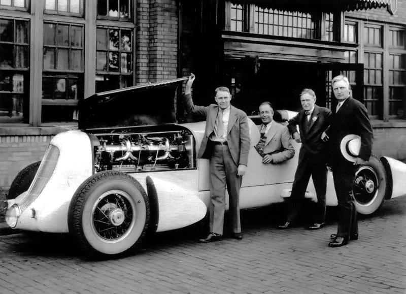
The newly completed Duesenberg Special in June 1935. From left to right: Augie Duesenberg, Ab Jenkins, Harvey Firestone, and John Thomas.

In the early-1930s, Jenkins organized a number of speed runs at Bonneville and set many records, including a flying 1 mi run at 65.45 mph (105.33 km/h) on an Allis-Chalmers tractor and a 24 hour run in a modified Pierce-Arrow at 127.229 mph (204.755 km/h), covering 3,053 mi (4,913 km). The endurance runs were on a 10 mi (16 km) circular course. These events made the Bonneville Salt Flats the premier destination for international contestants looking to set speed and endurance records.

In 1934, Jenkins was looking to better his 24 hour record. With the support of Errett L. Cord, whose company controlled Duesenberg Inc, a special Duesenberg car was built for Jenkins to set endurance records at Bonneville. Augie Duesenberg was involved with the design of this car. The endurance racer was originally known as the Duesenberg Special.

Jenkins Duesenberg Special

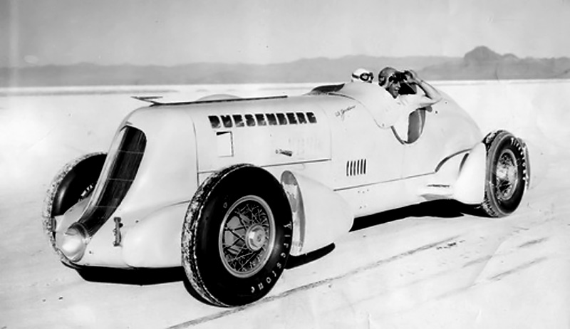
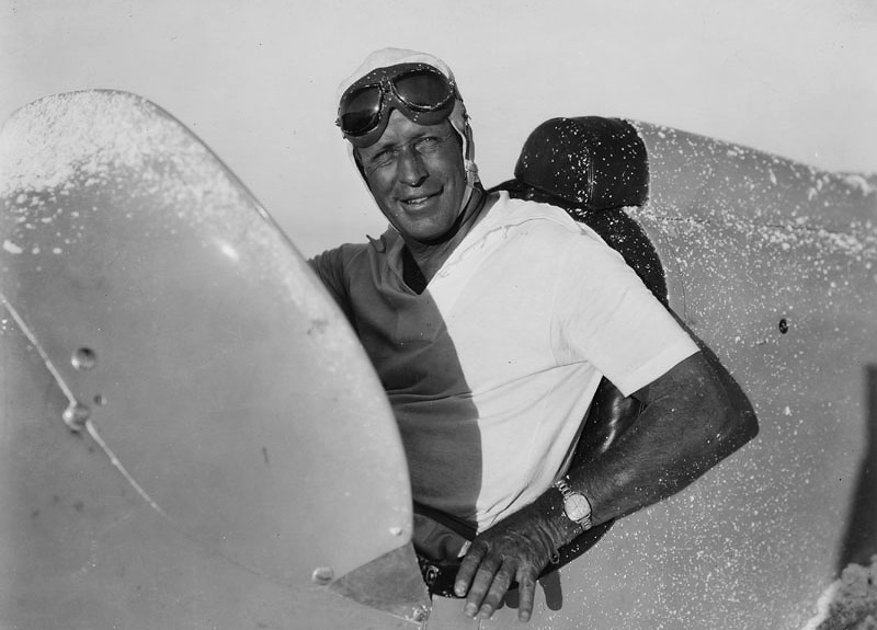
Ab Jenkins and the Duesenberg Special in their natural habitat: the Bonneville Salt Flats

The Duesenberg Special was built on a standard 142.5 in (3.62 m) Duesenberg J chassis and was intended to be driven on the street with minimal changes. For higher speeds, the gear ratio of the rear axle was dropped to 3.0 to 1. The car used a standard Duesenberg eight-cylinder, inline engine with a 3.75 in (95 mm) bore, 4.75 in (121 mm) stroke, and displacing 420 cu in (6.9 L). The engine was supercharged and had dual overhead camshafts. The standard engine produced 320 hp (239 kW); however, the Duesenberg Special’s engine had special grind camshafts, larger carburetors, a larger impeller for the supercharger, and updated intake manifolds that increased the engine’s output to 400 hp (298 kW) at 5,000 rpm. An identical spare engine was also built for the Duesenberg Special.

The body of the Duesenberg Special was designed by Herbert Newport and was streamlined to minimize the car’s frontal area. Newport’s design included a single headlight positioned below the sloped radiator. The two seats were staggered slightly to keep the car’s body narrow. The front suspension was lowered, and large Firestone tires were fitted onto 18 in (.46 m) wire wheels. Behind each wheel was a fairing designed to reduce air turbulence. Detachable fenders were used for normal road travel. The Duesenberg Special was 18.5 ft (5.64 m) long, had a 56.1 in (1.42 m) track, and weighed 4,800 lb (2,177 kg).

Jenkins Duesenberg Special pit

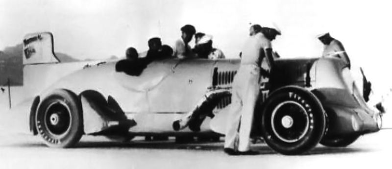
The Duesenberg Special makes a pit stop after a grueling run on the salt flats. Note the straight-pipe exhaust extending from the eight-cylinder Duesenberg engine to the back of the car.

Once completed, the Duesenberg Special was tested on the Indianapolis Motor Speedway and then shipped to Salt Lake City, Utah. Meanwhile, on the Bonneville Salt Flats in July 1935, Briton John Cobb had bested Jenkins’ 24 hour record in his aero-engined Napier-Railton racer. Cobb set the new mark in the 450 hp (336 kW) Napier Lion-powered machine at 134.850 mph (217.020 km/h)—over 7.5 mph (12 km/h) faster than Jenkins.

Jenkins and the Duesenberg Special were soon on the Bonneville Salt Flats. Jenkins quickly took the one hour record at 143.42 mph (230.81 km/h), but shortly after, an engine bearing burned out. A couple of weeks later, both engines were back from Indianapolis with new bearings, and Jenkins was back on the salt flats. Jenkins and his relief driver Tony Gulotta had run the Duesenberg Special for 1,960 mi (3,154 km) and averaged over 138 mph (222 km/h) when the engine failed. The spare engine was installed, and over 29 and 30 August 1935, Jenkins retook the 24-hour record by covering 3,354 mi (5,398 km) at an average of 135.580 mph (218.195 km/h)—less than one mph (1.6 km/h) faster than Cobb.

Jenkins Mormon Meteor pit

Ab Jenkins in the Conqueror-powered Mormon Meteor II. Note the rudimentary fin to increase the car’s directional stability at high speeds; it was one of many tried.

The new record was short lived. In September 1935, Capitan George Eyston, another Briton, upped the 24 hour record to 140.52 mph (226.15 km/h). Eyston used a 500 hp (373 kW) Rolls-Royce Kestrel V-12 aircraft engine in his streamlined Speed of the Wind racer to best Jenkins’ record by 5 mph (8 km/h).

Per an existing agreement, Jenkins purchased the Duesenberg Special for $4,500 (and $300 in expenses). A name change was in order, and the Salt Lake City Desert News held a contest to rename the car. The winning name was the Mormon Meteor. Jenkins knew that he would need more power to win back the record.

Like Cobb and Eyston, many land speed racers had switched to aircraft engines, and Jenkins saw the 400 hp (298 kW) eight-cylinder engine as the Duesenberg Special‘s weak point. Jenkins acquired two 1,570 cu in (25.7 L), 750 hp (559 kW), V-12 Curtiss Conqueror aircraft engines. One would be used in the Mormon Meteor and the other held as a spare.

Jenkins Mormon Meteor

The Mormon Meteor II in its final Curtiss Conqueror-powered form. Note the improved fin and additional lights.

Augie Duesenberg drew up the plans to shoehorn the Conqueror engine into the Mormon Meteor. A new bell housing, flywheel, clutch, and other parts for the conversion were made by the Lycoming Machine Company. Augie, aided by Marvin Jenkins, Ab Jenkins’ young son, oversaw the installation of a Conqueror engine in the Mormon Meteor at the Auburn auto plant in Auburn, Indiana in early 1936. Other modification included a tail fin to increase the vehicle’s directional stability at high speeds. The decision was made to rename the car Mormon Meteor II as a result of all the changes.

By this time, Eyston had returned to Bonneville and set new records. In the Speed of the Wind, Eyston upped the 24 hour record to 149.096 mph (239.947 km/h) and set a 48 hour record at 136.349 mph (219.432 km/h). Jenkins in the Mormon Meteor II beat Eyston’s 12 hour speed, averaging 152.84 mph (245.97 km/h), but was forced to quit shortly after with a failed drive shaft. While the Mormon Meteor II was down for repairs, Cobb took to the salt and beat Eyston’s 24 hour speed—averaging 150.163 mph (241.664 km/h).

Jenkins, with Babe Stapp as his relief driver, broke yet another set of records on 22 and 23 September 1936. The Mormon Meteor II averaged 153.823 mph (247.554 km/h) for 24 hours and 148.641 mph (239.215 km/h) for 48 hours—covering 3,692 mi (5,942 km) and 7,135 mi (11,483 km), respectively. On 21 and 22 September 1937, Jenkins, and relief driver Lou Meyer, increased the 24 hour record to 157.270 mph (253.102 km/h), covering 3,774 mi (6,074 km) in the Mormon Meteor II.

Ab Jenkins Mormon Meteor

Ab Jenkins in the cockpit of the Mormon Meteor II after running on the Bonneville Salt Flats.

As good as the Mormon Meteor II was, the Duesenberg chassis was not built for the heavy 750 hp (559 kW) engine. In 1937, Jenkins commissioned Augie Duesenberg to design a new car able to accommodate the Curtiss Conqueror. The new endurance racer was known as the Mormon Meteor III. The Mormon Meteor II had its Conqueror engine removed; the Duesenberg straight eight was reinstalled, and the car was made usable for normal road travel. Jenkins had the car painted burgundy and rechristened it the Mormon Meteor.

Ab and Marvin Jenkins used the Mormon Meteor for personal transportation as well as in parades in Salt Lake City, of which Ab Jenkins had been elected mayor. After putting another 20,000 mi (32,000 km) on the Mormon Meteor, Jenkins sold the car in 1943. The Mormon Meteor passed through a few owners until it was purchased at auction in 2004 by Harry Yeaggy for $4.45 million. Yeaggy had the car carefully restored to its original 1935 condition, earning it Best of Show at the Pebble Beach Concours d’Elegance in August 2007. That honor was followed by Best of Show wins at the Amelia Island Concours d’Elegance in March 2011, the Elegance at Hershey in June 2014, and the Arizona Concours d’Elegance in January 2016. The Duesenberg Special / Mormon Meteor is considered one of the most important Duesenberg automobiles in existence.

Duesenberg-SJ--Mormon-Meteor--Special

The beautifully restored Duesenberg SJ Mormon Meteor Special (returned to its 1935 configuration) at Pebble Beach, CA. (Wouter Melissen image via ultimatecarpage.com)

Sources:
Ab & Marvin Jenkins by Gordon Eliot White (2006)
– “They Always Called Him Augie” by George Moore, Automobile Quarterly, Vol. 30, No. 4 (1992)
http://www.hemmings.com/hcc/stories/2007/12/01/hmn_feature1.html
http://www.supercars.net/cars/2480.html
http://en.wikipedia.org/wiki/Speed_of_the_Wind
http://www.sportscardigest.com/amelia-island-concours-delegance-2011-best-of-show-winners/
http://www.sportscardigest.com/elegance-hershey-2014-report-photos/
http://blog.hemmings.com/index.php/2016/01/27/mormon-meteor-duesenberg-takes-best-of-show-at-arizona-concours-delegance/?refer=news

Hispano-Suiza Type 86 engine

Hispano-Suiza Type 86 Railcar Engine

By William Pearce

In the mid-1930s, Hispano-Suiza developed the Type 86 engine specifically for use in railcars. A railcar is a self-propelled railroad coach meant to carry passengers or cargo on routes that are not profitable enough to operate a regular locomotive pulling non-powered railroad cars.

Hispano-Suiza Type 86 engine

The Hispano-Suiza Type 86 railcar engine. From left to right across the top of the engine are the fuel pump, air compressor, carburetor (another on the opposite side), two magnetos with a speed governor, and two starters above the housing on the right. The oil cooler is positioned under the cylinder head.

Hispano-Suiza became involved in powering railcars with the adaptation of its six-cylinder automotive Type 56 engine of 487 cu in (8.0 L) and 46 hp (34 kW). In 1931, the V-12 Type 68 auto engine was bored out and modified for use in French “Micheline” (rubber-tired) railcars. This engine displaced 690 cu in (11.3 L) and produced 250 hp (186 kW). Unlike the previous Hispano-Suiza engines, the Type 86 engine was specifically designed for use in railcars.

The Type 86 was a horizontal (flat) 12-cylinder engine. The engine was designed to keep its height to a minimum so that it could be mounted transversely in place of one of the railcar’s bogies. The railcar’s drive wheels were connected by hydraulic couplings to gearboxes on both ends of the engine. This installation maximized the usable space in the railcar while lowering its center of gravity. Engine accessories, such as the compressor, carburetors, magnetos, and starters, were placed on top of the engine for ease of access and maintenance.

Hispano-Suiza Type 86 crankcase.

The two-piece aluminum crankcase for the Type 86 engine. Note the 14 long studs used to secure each cylinder bank to the engine.

With a 5.91 in (150 mm) bore and a 6.69 in (170 mm) stroke, the Type 86 displaced 2,200 cu in (36.05 L). The forged and hardened aluminum alloy flat top pistons had three compression rings and one scraper ring. Floating piston pins attached the pistons to tubular fork-and-blade connecting rods. The blade rod and its big-end cap meshed together through a tongue and grove design. Two tapered pins secured the blade rod around the crankshaft. The fork rod had a conventional big-end cap securing it around the crankshaft. Reportedly, these connecting rods and their bearings were the same as those used on some versions of the Hispano-Suiza 12Y V-12 aircraft engine. Although the Type 86 had the same bore and stroke as the 12Y, no other components were interchangeable.

The forged, chrome-nickel steel crankshaft was supported in the crankcase with seven main bearings and weighed 243 lb (110 kg). The single camshaft was positioned on top of the aluminum crankcase and was also supported by seven bearings. The camshaft was driven by the crankshaft via a helical spur gear at one end of the engine. This gear also drove the fuel pump and an air compressor for powering brakes and other accessories. At the other end of the engine, the camshaft drove two 12-cylinder magnetos and an engine speed governor.

Hispano-Suiza Type 86 crank and rods

The crankshaft and fork-and-blade connecting rods for the Type 86 engine. Note the blade rod with a tongue and groove design on the big end.

Each cylinder bank was attached to the crankcase by 14 long studs. Six open cylinder liners made of nitrided steel were installed in each aluminum cylinder bank. A single-piece, aluminum head (flathead) was attached to each cylinder bank by 50 bolts, in addition to the 14 long studs. The engine’s compression ratio was 5.85 to 1.

The intake and exhaust side valves were positioned parallel to and directly above the cylinder barrel. The valves opened into a small combustion space adjacent to the cylinder. The intake port and combustion chamber made the incoming air/fuel charge turbulent to allow for better mixing of gases. The chrome silicon valves were sodium-cooled and used three valve springs each. The valve seats were faced with Stellite for wear resistance. The valves were actuated by roller lifters. Two spark plugs were positioned in the cylinder head and directly above the valves. This position allowed the spark plugs to be easily accessed for maintenance.

Hispano-Suiza Type 86 head and cyl bank

At top is a complete cylinder bank assembly for the Type 86 engine. The middle image shows the same assembly as it would bolt on to the crankcase. At bottom is the flathead. Note the recessed space that formed the combustion chamber and allowed clearance for the side valves .

The Type 86 engine had pressure lubrication to all turning parts. Oil was drawn from the crankcase and sent though the engine via a pump located in the center of the crankcase. Two additional sump pumps drew oil from both ends of the crankcase. These pumps fed oil through oil coolers on both sides of the engine. The cooled oil was returned near the main pump in the crankcase.

A centrifugal water pump on each side of the engine drew cooling water from the radiator and through the oil cooler. After the water passed though the pump, it then flowed through the cylinder head and into the cylinder block via drilled passageways. The heated water would exit the top of the cylinder head via ports on both sides of the head and flow back to the radiator, positioned on the railcar.

Each side of the engine had one downdraft carburetor attached to an intake manifold located above the cylinder bank. Horizontal carburetors were proposed to reduce the engine’s height, but it is not known if they were ever used. The engine’s speed governor limited the engine to 2,500 rpm by regulating the butterflies of the carburetors. The exhaust manifold was also positioned above the cylinder bank, and its configuration varied depending on the engine’s installation.

Hispano-Suiza Type 86 intake and water pump

The downdraft carburetor, manifold, and water pump (not to scale) used on the Type 86 engine.

For starting the engine, the Type 86 used two 24 volt electric starters with a maximum speed of 3,500 rpm. The starters were geared to the engine at a reduction of 37 to 1 so that they would turn the engine over at less than 95 rpm. Although one starter could start the engine when it was warm, the starters acted in unison, and both were needed to start the engine when cold, turning the engine at 80 rpm.

Internal splines in each end of the crankshaft received a coupler used to connect the engine to a gearbox. The couplers used hydraulic clutches, and one of the two couplers had a ring gear for starting the engine. The couplers were not mechanically locked at full load, which ensured smooth transmission of power to the gearboxes. Each gearbox used electromagnetic gear selection for its planetary gear reduction. At one engine revolution, the four gear reduction speeds were 0.237, 0.389, 0.610, and 1.0.

Hispano-Suiza Type 86 cam piston and lifter

While not to scale, the camshaft, piston, and roller lifter for the Type 86 engine can be seen in the above image. Note the adjustment rod on the roller lifter to provide proper valve clearance.

With interruptions only for routine maintenance, the Type 86 was designed to provide continuous service for about a year, traveling 310–375 mi (500–600 km) per day. That service life worked out to around 125,000 mi (200,000 km) before an overhaul was scheduled. The power section of the engine was 58.1 in (1.475 m) long but grew to 122.4 in (3.109 m) with the couplers and gearboxes. The engine was 40.3 in (1.024 m) wide and 39.1 in (.993 m) tall. The Type 86 produced a continuous 550 hp (410 kW) at its normal operating speed of 2,000 rpm. But the engine could produce 650 hp (485 kW) at 2,000 rpm and 750 hp (560 kW) at 2,200 rpm.

A smaller engine called the Type 87 was also planned. This engine’s bore was reduced by 1.18 in (30 mm) to 4.72 in (120 mm). As a result, its total displacement was reduced by 792 cu in (12.98 L) to 1,408 cu in (23.07 L). It was believed this engine would develop 330 hp (246 kW). However, in the late 1930s, French industries were focused on rearming the French military, and few resources were available for other projects. Hispano-Suiza directed its attention to manufacturing aircraft engines, and development of the railcar engines was stopped.

Hispano-Suiza Type 86 GA

Side and top view drawings of the Hispano-Suiza Type 86 engine.

Sources:
Notice Descriptive du Moteur Hispano Suiza Type 86 by Hispano-Suiza (~1936)
Hispano Suiza in Aeronautics by Manuel Lage (2004)

Northrop YC-125 JATO

Northrop N-23 Pioneer and N-32 / YC-125 Raider

By William Pearce

As World War II wound down, Northrop looked for opportunities to expand its aviation products. At the time, various reports forecasted a need for a rugged, low-cost, transport aircraft to serve under-developed airfields for emerging commercial routes following World War II. To meet that need, Northrop designed and built the N-23 Pioneer transport at its own expense. The Pioneer was unlike any aircraft that Northrop had built.

Northrop N-23 Pioneer

The Northrop N-23 Pioneer seen shortly after its rollout at Hawthorne, California and before its registration (NX8500H) was applied. Note the single window along the fuselage.

The N-23 Pioneer was a trimotor, high-wing aircraft of all-metal construction. Its robust fixed landing gear, with long struts, enabled the aircraft’s use on unimproved runways. To allow for short-field operation, large flaps made up 80% of the wing’s trailing edge. In addition, another wheel could be added to the inboard side of each main gear strut to reduce the aircraft’s load footprint for soft field operation. Outboard of the large flaps were small ailerons that acted with wing spoilers to control the aircraft’s roll. This configuration was similar to that used on the Northrop P-61 Black Widow.

The Pioneer was engineered with remote field operations in mind. Common parts were used when possible; all three engine installations were identical, as were the vertical and horizontal stabilizers. The Pioneer was designed with large panels to allow easy access to critical parts for maintenance and repair.

Northrop N-23 take off

The Northrop Pioneer performing a short field takeoff from the Conejo Valley Airport in Southern California. The Pioneer’s short field performance enabled it to operate out of airfields normally limited to small aircraft. Note that the fuselage has been modified with passenger windows.

The Pioneer could be fitted with 36 seats for passenger service or carry up to 10,000 lb (4,536 kg) of cargo. Quick-change fittings were featured in the floor of the Pioneer’s cabin; they enabled easy reconfiguration of the aircraft’s interior from passenger transport to cargo transport. Long objects (such as pipe or timber) up to 36 ft (11 m) could be loaded through a hatch under the aircraft’s nose.

The Pioneer was powered by three 800 hp (597 kW) Wright R-1300 engines. Each engine turned a fixed-pitch, two-blade Hamilton Standard propeller. The aircraft had an 85 ft (25.9 m) wingspan and was 60 ft 7 in (18.4 m) long. It had a maximum speed of 193 mph (311 km/h), a cruising speed of 150 mph (241 km/h), and a range of 1,750 mi (2,816 km).

Northrop YC-125 Raider

YC-125 Raiders on the Northrop production line. Note the various engine access panels. The wings’ leading edge panels allowed access to fuel lines, control cables, and wiring.

First flown on 21 December 1946 by Max Stanley, the Pioneer proved to be a very capable aircraft. It could take off in fewer than 400 ft (122 m). At a gross weight of 25,500 lb (11,567 kg), the Pioneer could take off in 700 ft (213 m) and land in 600 ft (183 m). The aircraft was operated out of various unimproved and short fields in Southern California. Unfortunately, with the influx of cheap, surplus World War II transports available in the post-war marketplace, there was little interest in the rugged Pioneer.

After a year of test flights, the Pioneer was used to test an experimental dorsal fin. During a flight on 19 February 1948, the fin broke loose and damaged the Pioneer’s tail surfaces, making the aircraft uncontrollable. Test pilot Latham A. “Slim” Perrett did what he could to steady the aircraft to allow the copilot and an engineer to parachute to safety. Sadly, there was no time for Perrett to escape.

Northrop YC-125 air

A Northrop YC-125B on a flight by the coast. Note the redesigned empennage compared to the Pioneer.

Despite the crash, the Air Force was interested in the Pioneer’s capabilities. In March 1948, Northrop was issued a contract for 13 aircraft developed from the Pioneer. The new aircraft was the N-32 Raider and was designated YC-125 by the Air Force. The first version was the YC-125A, an assault transport. An order for 10 additional YC-125B aircraft followed. The YC-125B was intended for Arctic rescue. The two versions of the YC-125 differed only in internal equipment.

Northrop YC-125 JATO

A Northrop YC-125 Raider uses six JATO bottles to take off fully loaded in under 500 ft (152 m).

The YC-125 Raider was very similar to the Pioneer, but it had a redesigned rear fuselage that incorporated a 9 ft (2.7 m) by 6 ft 6 in (2.0 m) ramp for loading and unloading equipment. The addition of the loading ramp led to a redesign of the aircraft’s empennage. The YC-125’s tailwheel strut could be extended to allow for better loading ramp access. Six JATO (jet-assisted take off) bottles could be used to enable a fully loaded 40,900 lb (15,552 kg) YC-125 to take off in 500 ft (152 m).

The YC-125 was powered by three 1,200 hp (895 kW) Wright R-1820 engines. Each engine turned a constant speed, three-blade Curtiss Electric propeller. The propellers’ pitch could be reversed to shorten the landing distance to as little as 330 ft (100 m). The aircraft had an 86 ft 6 in (26.4 m) wingspan and was 67 ft 1 in (20.4 m) long. The YC-125 had a maximum speed of 207 mph (333 km/h) and a cruising speed of 171 mph (275 km/h). The aircraft’s maximum range was 1,850 mi (2,977 km), and it could carry 32 troops or 12,000 lb (5,443 kg) of cargo.

The YC-125 made its first flight on 1 August 1949 with Stanley at the controls. Initial flight tests went well, and all 23 aircraft were delivered to the Air Force by the end of 1950. However, the YC-125 was found to be underpowered during service trials. As a result, the aircraft was thought to have little use in its intended roles. The Air Force had other, more versatile aircraft and helicopters that could be used in place of the YC-125s. Soon, all YC-125s were stationed at Sheppard Air Force Base in Texas and used for ground instructional training. In 1955, they were declared surplus, and around 19 YC-125s were sold to Frank Ambrose Aviation in Florida. That company then resold many of the YC-125s to various entities in South America, where they were used as rough field transports. Some served into the 1970s, doing the type of work for which the N-23 Pioneer was originally designed.

Northrop YC-125A Pima

The Northrop YC-125A of the Pima Air & Space Museum. This aircraft was donated by Robert A. Gallaher. (Pima Air & Space Museum image)

There are two known surviving YC-125s. Both were recovered after their service in South America. The Pima Air & Space Museum in Tuscon, Arizona has a YC-125A still in the livery it wore while serving for Triplay y Maderas de Durango, S.A., a lumber company in Durango, Mexico. The National Museum of the United States Air Force (NMUSAF) in Dayton, Ohio has a YC-125B. This aircraft was recovered from Zacateas, Mexico by Asher Ward and Darryl Greenamyer in the early 1990s.

Ward and Greenamyer had previously recovered a YC-125A for the NMUSAF, but the aircraft crashed in Tulsa, Oklahoma on 29 June 1988. As a result of a corroded wire, the propeller of the left engine went into reverse pitch shortly after takeoff. Ward and Greenamyer escaped with minor injuries. This was the last flight of the last airworthy YC-125.

Northrop YC-125B NMUSAF

The Northrop YC-125B of the National Museum of the United States Air Force. Note the additional main wheel added to the inboard side of each main gear strut. (NMUSAF image)

Sources:
Northrop: An Aeronautical History by Fred Anderson (1976)
American Military Transport Aircraft Since 1925 by E. R. Johnson (2013)
http://www.nationalmuseum.af.mil/factsheets/factsheet.asp?id=784
http://www.warbirdinformationexchange.org/phpBB3/viewtopic.php?p=167612
http://newsok.com/rare-airplane-loses-power-crashes-at-airport-in-tulsa/article/2230816
http://www.ntsb.gov/aviationquery/brief.aspx?ev_id=20001213X25943&key=1

Short Silver Streak

Short Swallow / Silver Streak

By William Pearce

H. Oswald Short and his brother Eustace founded Short Brothers in London, England in 1908. In 1916, they became acquainted with duralumin when their firm took over construction of two airships that used duralumin components. Duralumin is an aluminum alloy that incorporates copper, manganese, and magnesium for increased hardness. Fabric and wood were used to build aircraft at the time, but from his experience, Oswald believed that duralumin was a far superior building material for aircraft construction. A duralumin aircraft would be stronger than a wooden aircraft, and it would also be resistant to warping, fire, and rot.

Short Silver Streak

Factory photo of the Short Swallow / Silver Streak shortly after its completion in 1920. The aircraft’s riveted construction is evident in this image. Note the cargo compartment in front of the cockpit (between the upper wing’s cabane struts) is covered over.

Oswald extensively tested various duralumin-built components with the intent of using duralumin for aircraft construction. Many wondered whether or not duralumin would resist corrosion. To prove the metal was up to the task, Oswald affixed duralumin and mild-steel plates to a jetty so that they were exposed at low tide and submerged in the sea at high tide. After nine months, the duralumin had only light surface corrosion, while the steel plates had nearly rusted away.

Reassured of duralumin’s corrosion resistance, Oswald designed an all-metal aircraft in 1919. He sought funding from the British Air Ministry to build a prototype but was turned down because of the unproven duralumin construction. Short Brothers was so confident in duralumin’s merits that in 1920, at their own expense, they began constructing the aircraft Oswald designed. The aircraft was quickly completed and made its debut at the Olympia Air Show in London on 9 July 1920. Originally, the aircraft was named Swallow, but its name was changed to Silver Streak after the show.

Short Silver Streak Olympia

The Short Swallow (later renamed Silver Streak) on display at the Olympia Air Show in 1920, where the polished all-metal aircraft attracted a lot of attention.

The Short Swallow / Silver Streak was the first all-metal aircraft built in Great Britain; no wood or fabric was used. The structure of each wing was made up of two steel spars with duralumin ribs sweated on. The wings and tail were skinned with sheet aluminum riveted to their respective frames. The fuselage’s frame had an oval cross section and was made of duralumin. Duralumin sheets were riveted to the duralumin airframe to make up the aircraft’s skin. Thicker duralumin sheets were used around the cockpit, and the front of the fuselage was enclosed by a single duralumin sheet, making a fireproof bulkhead.

The Silver Streak was powered by a water-cooled, 240 hp (179 kW), straight, six-cylinder Siddeley Puma engine. The aircraft was designed for a pilot and 400 lb (181 kg) of cargo in front of the cockpit. However, modifications would easily allow the aircraft to carry a passenger in place of the cargo. The Silver Streak had a wingspan of 37 ft 6 in (11.4 m) and a length of 26 ft 5 in (8.1 m). It had an empty weight of 1,865 lb (846 kg) and a loaded weight of 2,870 lb (1,302 kg). The Silver Streak’s max speed was 125 mph (201 km/h), and it had a 450 mile (724 km) range.

The Silver Streak made quite an impression at the Olympia show. However, many remained skeptical of its duralumin construction. This skepticism led to the Silver Streak being refused its Certificate of Airworthiness. However, the British Air Ministry agreed to purchase the Silver Streak to evaluate its all-metal aircraft construction. The Silver Streak was first flown on 20 August 1920 by John Parker at the Isle of Grain in Britain. The thin aluminum wing and tail skins were found to lack the needed strength and were replaced with duralumin sheeting. The Sliver Streak took to the air again on 27 January 1921 and was delivered to the Royal Aircraft Establishment at Farnborough in February. During the flight to Farnborough, it was noted that the aircraft cruised at over 120 mph (193 km/h).

Short Silver Streak side

The Short Silver Streak after its delivery to Farnborough in February 1921. The cargo compartment has been converted to carry a passenger.

At Farnborough, the Silver Streak received the Air Ministry serial number J6854 and was flown on a few test flights through June 1921. Testing revealed the aircraft could climb to 10,000 ft (3,048 m) in just 11 minutes and had a top speed in excess of 125 mph (201 km/h). Pilots noted the Silver Streak’s quick acceleration, steadiness in the air, and ease of control. However, the test flying was very limited, and after June the aircraft was relegated to static testing.

Nothing was heard of the Silver Streak for over a year, and then the Air Ministry reported that it had tested the aircraft to destruction. During that time, no corrosion issues were encounter with the duralumin. In wing-loading tests, the wing failed just above its calculated ultimate stress level when a spar buckled. However, even with the buckled spar, the wing still possessed enough structural integrity for normal flight. The tail and rudder were separately tested and failed under a load far in excess of what a wooden tail and rudder could withstand. The fuselage survived a 2,000 lb-ft (2,712 N•m) torsion test with no visible distortion. The fuselage was then subjected to 100 hours of vibration tests which revealed no signs of cracks or loose rivets.

Satisfied with the results and believing that all-metal construction was sound, the Air Ministry ordered two prototypes of a Short two-seat fighter sea plane in January 1922. Financial concerns caused this order to be cancelled in June 1922. However, the Silver Streak was used as the basis for the Short Springbok, and its construction techniques were employed in future aircraft.

Short Silver Streak front

A good view of the Silver Streak illustrating how the Siddeley Puma engine was exposed to the airstream to aid cooling.

Sources:
Shorts Aircraft since 1900 by C. H. Barns (1967/1998)
British Prototype Aircraft by Ray Sturtivant (1995)
– “The Olympia 1920 Aero ShowFlight (22 July 1920)
– “Air Ministry Acquire Short ‘Silver Streak’Flight (24 February 1921)
– “Short Bros. and Metal ConstructionFlight (11 December 1924)

savoia-marchetti s64 take off

Savoia-Marchetti S.64 and S.64 bis

By William Pearce

Inspired by Charles Lindbergh’s New York to Paris transatlantic flight of 3,600 miles (5,800 km) in May 1927, Italian pilot Arturo Ferrarin discussed with Alessandro Marchetti the possibility of building an aircraft to set non-stop distance records. Ferrarin was an experienced long distance flyer, having flown from Rome to Tokyo in 1920. Marchetti was the chief designer for Savoia-Marchetti and had complete control of the aircraft’s design and configuration. What emerged from Marchetti’s drafting table was the S.64. The Italian Air Ministry supported the project as a way to demonstrate the capabilities of Italian aviation to the world; two S.64 aircraft were ordered in late 1927.

savoia-marchetti s64 take off

The Savoia-Marchetti S.64 taking off from Montecelio. The retractable radiator can be seen under the wing and just behind the fuselage nacelle.

The Savoia-Marchetti S.64 was an aircraft of a rather unorthodox configuration yet similar to Marchetti’s earlier flying boat design, the S.55. Unlike the twin-hulled S.55 flying boat, the S.64 was a landplane. The S.64 consisted of a large, thick cantilever wing. A fuselage nacelle was blended into the center of the wing. The nacelle protruded below the wing and extended beyond its leading edge, but it was part of the wing’s structure. The pilot and copilot sat side-by-side and were provided with a rest area for long-distance flights. The wing and fuselage nacelle were made of wood and skinned with plywood. The wing housed 27 fuel tanks that combined to accommodate 1,717 gallons (6,500 L) of fuel.

Two frame booms made of duralumin extended behind the wing and supported the S.64’s slab horizontal stabilizer. Attached to the center of the horizontal stabilizer was the vertical stabilizer and rudder. Large control surfaces were attached to the trailing edge of both the horizontal and vertical stabilizers. Reportedly, the incidence of the horizontal and vertical stabilizers could be adjusted to trim the aircraft. The fixed main gear was faired and was suspended via struts under the wing. A tail skid was attached to the end of each boom.

savoia-marchetti s64 ferrarin del prete

Arturo Ferrarin, Carlo Del Prete, and the S.64.

A single FIAT A.22T V-12 engine was supported on struts above the wing. The FIAT A.22T was liquid-cooled and had a 5.3 in (135 mm) bore and 6.3 in (160 mm) stroke. The engine displaced 1,677 cu in (27.5 L) and produced 550 hp (410 kW). With the exception of its valve covers, the engine was encased in a streamlined cowl. At the very front of the cowl was a large oil tank for the engine. The pusher engine turned a two-blade wooden propeller with a streamlined, pointed spinner. Coolant from the engine traveled down the supporting struts into a radiator under the rear of the wing. The semi-retractable radiator could be extended below the wing for increased airflow.

The S.64 had a 70.5 ft (21.5 m) wingspan and was 34.1 ft (10.4 m) long. The aircraft had an empty weight of 5,291 lb (2,400 kg). Its useful load was 10,141 lb (4,600 kg), resulting in a maximum weight of 15,432 lb (7,000 kg)—nearly three times its empty weight. Its top speed was 146 mph (235 km/h), and cruise speed was around 100 mph (160 km/h). Takeoff speed with a heavy load was 93 mph (150 km/h). The S.64’s maximum range was estimated as 7,146 miles (11,500 km).

savoia-marchetti s64 Brazil

Brazilians assist the S.64 after it landed on the beach near Touros.

The first S.64, registered as I-SAAV, was first flown on 3 April 1928 at Cameri airfield in northern Italy by Alessandro Passeleva. The aircraft was then flown by Arturo Ferrarin and Carlo Del Prete, two men who would become very experienced in the S.64. Initial flight tests revealed the aircraft had a high takeoff speed that necessitated a smooth runway. On 18 April, Ferrarin flew the S.64 to Aeroporto Alfredo Barbieri in Montecelio, near Rome, where a special 4,265 ft (1,300 m) runway had been prepared. The beginning of the runway was paved and had a 6.5 percent grade to aid the aircraft’s initial acceleration. The rest of the runway had a 0.56 percent grade and was unpaved. Flight testing continued with progressively larger fuel loads, and a larger 9.8 ft (3.0 m) diameter propeller was fitted

On 31 May, Ferrarin and Del Prete took off with 921 gallons (3,486 L) of fuel in an attempt to set a new closed circuit distance record. The circuit was from Casale dei Prati in Montecelio to the tower at Torre Flavia (west to the coast) then south to the lighthouse at Anzio (by the coast) and back to Montecelio. After 58 hours and 34 minutes, Ferrarin and Del Prete landed at Montecelio on 2 June after traveling 4,763.82 miles (7,666.62 km) at an average speed of 86.48 mph (139.18 km/h). The S.64, with Ferrarin and Del Prete, had set new records for endurance, distance, and speed over a 5,000 km course. The S.64 beat the endurance record set by Americans Edward Stinson and George Haldeman, who flew for 53 hours and 35 minutes in a Stinson Detroiter aircraft in late March 1928.

savoia-marchetti s64 bis

A side view of the S.64 bis illustrating the duralumin booms that attached the tail to the rest of the aircraft.

The S.64 was then prepared for its next record flight—a straight-line flight of over 5,800 miles (9,300 km) from Montecelio to Rio de Janerio, Brazil. However, that plan was changed on account of high temperatures in Montecelio that would have necessitated a longer takeoff run. The runway at Montecelio had already been extended by 1,312 ft (400 m); its length was now 5,577 ft (1,700 m), but that would not be enough. The new destination was Bahia (now Salvador), Brazil, some 5,280 miles (8,500 km) away. The shorter flight allowed the fuel load to be reduced by 370 lb (168 kg), from 8,377 lb (3,800 kg) to 8,007 lb (3,632 kg).

On the evening of 3 July, Ferrarin and Del Prete departed Montecelio and headed southwest. The S.64 traveled toward Gibraltar and then headed down the coast of Africa and out across the Atlantic. On the afternoon of 5 July, Ferrarin and Del Prete crossed the Brazilian coastline, only to discover thick fog below. After searching in vain for a landing strip, they went back to the coast and set the S.64 down on the beach near Touros, Brazil. Landing in the sand damaged the S.64’s landing gear and fuselage. Not accounting for the distance flown looking for a landing strip, the S.64 set a new straight-line distance record of 4,466.58 miles (7,188.26 km). The flight was 49 hours and 15 minutes. Later, the S.64 was taken by ship to Rio de Janerio and donated to Brazil. (Unfortunately, Del Prete died in Brazil on 16 August 1928 from injuries suffered in the crash of another aircraft. A monument honoring Del Prete and the S.64’s flight was built in the Praça Carlo Del Prete in Laranjeiras, Rio – Rio de Janeiro, Brazil.)

savoia-marchetti s64 bis flight

The S.64 bis in flight showing the similar engine, wing, and boom configuration to the S.55.

Later in July after the S.64’s flight to Brazil, the Germans took the S.64’s endurance record with Johann Risztics and Wilhelm Zimmermann flying for 65 hours and 25 minutes in a Junkers W 33. Italy wanted the record back, and so the second S.64 was built. Finished in early 1929, the aircraft was designated S.64 bis to indicate changes made from the first S.64. The S.64 bis had a longer windscreen and a variable-pitch metal propeller.

Umberto Maddalena and Fausto Cecconi were selected to fly the S.64 bis, registered as I-SAAT. While flight testing was delayed in late 1929 because of bad weather, the French pilots Dieudonné Costes and Paul Codos took the S.64’s distance record. Flying in a Breguet 19 in mid-December, Costes and Codos traveled 4,989.26 miles (8029.44 km). Now the challenge was to set new endurance and distance records, and the S.64 bis would not disappoint.

savoia-marchetti s64 bis landing

The Savoia-Marchetti S.64 bis coming in for a landing.

On 30 May 1930, Maddalena and Cecconi took off from Montecelio in the S.64 bis and followed the same closed circuit course that the S.64 had traveled. Landing on 2 June (the second anniversary of Ferrarin and Del Prete’s flight), Maddalena and Cecconi and the S.64 bis were the new endurance and distance record holders. Their 67 hour, 13 minute, and 55 second flight had covered 5,088.28 miles (8,188.80 km).

Unfortunately the S.64 bis would set no additional records. On 19 March 1931, Maddalena and Cecconi and radio operator Giuseppe Da Monte embarked on a flight from Cinisello (near Milan) to Montecelio. About halfway into their flight, near Pisa, a failure occurred and the S.64 bis crashed into the sea off Calambrone. It is believed that the FIAT’s crankshaft broke, allowing the propeller to cut into the wing and fuselage nacelle of the S.64 bis. However, a definitive cause was never found. Tragically, Maddalena, Cecconi, and Da Monte were killed in the crash.

Carlo Del Prete memorial

The Carlo Del Prete memorial in Rio de Janeiro, Brazil. A sculpture of the S.64 flies above a stature of Carlo Del Prete as he stands before a plaque detailing the record flight. (Silvio Cezar Scremin image)

Sources:
Aeroplani S.I.A.I. 1915-1930 by Giorgio Bignozzi and Roberto Gentilli (1982)
SIAI Pagine Di Storia (1976)
Italian Civil and Military Aircraft 1930-45 by Jonathan W. Thompson (1963)
Jane’s All the World’s Aircraft 1931 by C. G. Grey (1931)
“The Rome—Brazil Non-Stop Flight” Flight (12 July 1929)
“Well-known Italian Pilots Killed” Flight (27 March 1931)
“The Accident to the S.64” Flight (3 April 1931)
http://archive.is/cNtFo
http://en.wikipedia.org/wiki/Savoia-Marchetti_S.64

Myasishchev M-50 bottom

Myasishchev M-50 / M-52 Bounder

By William Pearce

In the midst of the cold war, the United States and the Soviet Union constantly sought to outdo one another or at least match each other. As the United States was developing the Convair B-58 Hustler bomber capable of Mach 2 speeds, the Soviet Union endeavored to design and build its own Mach 2 bomber. In 1955, the V. M. Myasishchev Experimental Design Bureau, or OKB-23 (Opytno-Konstruktorskoye Byuro-23), was tasked to develop the new Mach 2 strategic bomber. Under chief designer Georgi Nazarov and with the assistance of the TsAGI (Tsentral’nyy Aerogidrodinamicheskiy Institut, the Central Aerohydrodynamic Institute), a number of designs were evaluated and tested in a wind tunnel. Ultimately, a design was chosen that could meet the desired performance goals and was technically feasible to build. This aircraft became the Myasishchev M-50.

Myasishchev M-50 flyby

The Myasishchev M-50 with a MiG-21 escort, giving some perspective to the size of the M-50.

In general, the M-50 resembled an enlarged Mikoyan-Gurevich MiG-21. The M-50 was comprised of a long, slender fuselage with a large delta wing mounted in the middle. The fuselage had a circular cross-section with a bulge that ran down its spine for control and fuel lines. All fuel was housed in the fuselage and could be transferred between the extreme fore and aft tanks to counteract trim changes as the M-50 accelerated to or decelerated from supersonic flight.

The pilot and co-pilot sat in tandem at the very front of the aircraft. The M-50 was designed to operate at very high altitudes, and the crew was required to wear pressure suits in case of cabin depressurization or ejection. The aircraft was fitted with downward-ejecting seats. This configuration also facilitated crew entry and exit; the hatch under each seat opened and the seat lowered for access.

Myasishchev M-50 ground hatch

The M-50 with the hatches under the crew positions open. Also note the open bomb bay. The sole M-50 was painted with various radio call numbers.

The M-50’s wings were very thin and could not house any fuel. Under each wing was a pylon-mounted engine about 2/3 of the way toward the wingtip. On the top of the wing and above the engine pylon was a wing fence. Each wing had a second engine mounted at its tip. The wing was swept back 50 degrees from its root to the inboard engine and 41.5 degrees to the second engine at its tip (some sources say the sweep was 57.57 and 54.42 degrees respectively). The wing featured large, rectangular, double-slotted flaps and tapered outboard ailerons. Reportedly, when the flaps were deployed, the ailerons dropped down to further reduce the M-50’s landing speed. All three tail surfaces, including the vertical stabilizer, were all-moving. Each tail surfaces had an anti-flutter weight barb extending from its tip. All flight control surfaces were hydraulically operated.

The M-50’s landing gear was of bicycle configuration, with a four-wheel bogie located both fore and aft of the bomb bay. Additional forward retracting outrigger gear was mounted just inboard of each wingtip engine. In order to accommodate a weapons bay large enough to carry the 36 ft 1 in (11 m) long M-61 cruise missile, the rear main gear was placed near the tail, well behind the aircraft’s center of gravity. This gear placement drastically increased the speed needed for rotation at takeoff, perhaps even making takeoff impossible. To alleviate this issue, the M-50’s nose gear was equipped with a double-extension hydraulic strut. At 186 mph (300 km/h) the strut would automatically extend, rotating the aircraft 10 degrees nose-up. The gear also had an emergency steel skid that could be hydraulically lowered to the runway upon landing, acting as a drag anchor, in case there was an issue with the standard three-parachute braking system.

Myasishchev M-50 rear

A rear view of the Myasishchev M-50 showing its all-movable tail surfaces. Also note the hump that housed fuel and control lines running along the aircraft’s spine.

The M-50 was 188 ft 7 in (57.48 m) long, had an 82 ft 4 in (25.1 m) wingspan, and was 27 ft 1 in (8.25 m) tall. The aircraft’s empty weight was 173,855 lb (78,860 kg), and its maximum weight was 319,670 lb (145,000 kg). The M-50’s forecasted performance included a service ceiling of 45,930 ft (14,000 m), a range of 8,075 mi (13,000 km), a bomb load of 11,000 lb (5,000 kg), and a top speed of 1,210 mph (1,950 km/h), or Mach 1.84.

Construction of the M-50 began in April 1956. Originally, the M-50 was to be powered by four Zubets RD-16-17 afterburning turbojets with 40,765 lb (181.32 kN) of thrust. However, the aircraft’s construction outpaced the engine’s development. When the M-50 was rolled out in July 1958, four non-afterburning Dobrynin VD-7BA turbojets of 21,495 1b (95.61 kN) thrust had been temporarily installed. The aircraft was re-designated M-50A as a result of the engine change.

In October 1958, the M-50A was disassembled and moved to the Zhukovskiy flight test center. Here it underwent taxi tests that indicated further modifications were needed. After the modifications, M-50A finally took to the air on 27 October 1959 with Nikolay I Goryainov and A S Lipko at the controls. Initial flight testing progressed rapidly; however, the M-50A was damaged in a ground accident on 12 May 1960. During an engine run-up, the aircraft jumped its wheel chocks and collided with the parked Myasishchev 3ME bomber prototype. The 3ME was scrapped as a result of the damage, but the M-50A was repaired and flying again in two months.

Myasishchev M-50 bottom

The Myasishchev M-50 makes a pass at the Tushino Air Show on 9 July 1961. Note the similar layout of the M-50 and its MiG-21 escorts.

In April 1961, the two inner VD-7BA turbojets were swapped with afterburning VD-7AM engines of 35,275 lb (156.91 kN) thrust. Slightly derated VD-7BA engines of 20,945 lb (93.16 kN) thrust were installed on new wingtip mounts. These mounts were wingtip extensions that housed new rearward retracting outrigger gear and increased the wingspan by 32 ft 10 in (10 m) to 115 ft 2 in (35.1 m). All engine installations were redesigned to incorporate ram inlets above the nacelle for additional cooling airflow.

Flight tests continued. With the underpowered engines installed, the M-50A was unable to achieve supersonic flight. Even in a shallow dive from altitude, the aircraft’s speed would not go above Mach 0.99, or 650 mph (1,050 km/h). In addition, the M-50A’s range fell 2,110 mi (3,400 km) short of expectations to 5,965 mi (9,600 km). During flight tests, the sole M-50A was painted with a various radio call numbers—023, 022, 12, and 05—to confuse any western observers.

Myasishchev M-52 mock-up

The Myasishchev M-52 mockup. Note the side-by-side cockpit configuration and the missile positioned near its mount under the wing. The small horizontal stabilizer is barely visible on top of the tail.

On 9 July 1961, the M-50A was escorted by two MiG-21 fighters as it made a flyby pass at the Tushino Air Show near Moscow. Western observers were impressed by the large, exotic, and loud aircraft. This appearance resulted in NATO assigning the codename “Bounder” to the M-50. However, what the observers did not know was that this was the M-50A’s last flight. It had only flown 19 times.

The M-52, a further development of the M-50, had been under construction since November 1958. The M-52 retained the four Zubets RD-16-17 engines (some say RD-17-18 engines rated at 39,020 lb / 173.58 kN). The wingtip engines were mounted on larger extensions. The M-52 had side-by-side seating for the pilot and co-pilot, and a third crew member was stationed in its nose. A small, delta-shaped horizontal surface was added to the top of the vertical stabilizer. Planned weapon upgrades for the M-52 included twin tail guns and provisions to attach a cruise missile on each side of its fuselage, under the wings.

Myasischev_M-50_@_Central_Air_Force_Museum OMP

The Myasischev M-50 on display in the Central Air Force Museum at Monino Airfield. (Maarten image via Wikimedia Commons)

Soviet Premier Nikita Krushchev felt future offensive and defensive weapons would be based on intercontinental ballistic missiles (ICBMs) rather than strategic bombers. As a result, the Myasishchev M-50 and M-52 projects were cancelled. OKB-23 was closed, and its personnel were redirected to another organization for ICBM work.

The M-50A and the nearly finished M-52 eventually ended up parked at Ramenskoye Airport in Zhukovsky (near Moscow), Russia. In 1968, the M-50A was relocated to the Central Air Force Museum at Monino Airfield (also near Moscow) where it is currently on display. The M-52 was scrapped in the 1970s.

Below is a video of the Myasishchev M-50 uploaded to YouTube.

Sources:
Soviet X-Planes by Yefim Gordon and Bill Gunston (2000)
Aircraft of the Soviet Union by Bill Gunston (1983)
http://www.airvectors.net/avbison.html
http://www.testpilot.ru/russia/myasishchev/m/50/m50_e.htm
http://www.testpilot.ru/russia/myasishchev/m/52/m52.htm
Unflown Wings by Yefim Gordon and Sergey Komissarov (2013) *No real info on the M-50 or M-52 but does contain a number of other projects that are often attributed to these aircraft.

Lancia V-12 aircraft engine side

Lancia Tipo 4 and Tipo 5 V-12 Aircraft Engines

By William Pearce

Vincenzo Lancia was born near Turin, Italy in 1881. From an early age, he demonstrated an aptitude in mathematics, and his father encouraged him to become an accountant. However, Lancia was mainly interested in machinery and engineering. By the age of 17, he worked as a bookkeeper for a small bicycle and auto repair shop, operated by the Ceirano brothers. There, he became more of a mechanic’s assistant than a bookkeeper. When the shop built an automobile, FIAT bought the business and made Lancia, who was only 19, chief inspector of their new factory and also a test driver. His driving skills impressed FIAT, and they later made him a race car driver.

Lancia V-12 aircraft engine

The Lancia Tipo 4 V-12 aircraft engine displaying its individual cylinders and distinct valve train. The engine was configured for pusher installations, which is why exhaust was expelled toward the propeller.

But Lancia wanted to design. In 1906, at the age of 25, he and another FIAT worker founded their own car company: Lancia & Company. Lancia and his company produced a number of vehicles and engines and became known throughout Europe. Always experimenting and innovating, Lancia took out patents for a narrow Vee engine configuration and an offset crankshaft in 1915. World War I interrupted plans to use the design for an automotive engine but gave Lancia incentive to build an aircraft engine.

Known as the Tipo 4 (Type 4), the Lancia V-12 aircraft engine was water cooled and had a 50-degree angle between the cylinder banks. The engine’s individual steel cylinders were mounted to its aluminum crankcase, with a deep oil pan. Each cylinder had one intake and one exhaust valve perpendicular to the cylinder axis. These horizontal valves opened into a small, rectangular clearance space above the cylinders that extended the combustion chamber above the piston. The valves were actuated by long rocker arms positioned in the Vee of the engine. A single hollow camshaft positioned in the middle of the Vee acted upon the rocker arms. The camshaft was driven from the crankshaft at the rear of the engine. The valve train was very similar to that later used on the Duesenberg Model H aircraft engine.

Lancia V-12 aircraft engine stand

Two technicians stand next to the Tipo 4 engine. Note the straight exhaust stacks. This is thought to be the prototype Tipo 4, and it closely resembles the engine that is preserved in the FIAT/Lancia archives.

Each cylinder had two spark plugs that were positioned on the opposite side from the valves. Two magnetos were located at the rear of the engine, each firing one spark plug per cylinder. One of the magnetos could be replaced by a distributor. Two Claudel-Lancia carburetors were mounted on each side of the engine. Each carburetor supplied air to three cylinders via a manifold that looped above the cylinders. A section of the intake manifold was jacketed to use engine cooling water to heat the air/fuel mixture as it traveled to the cylinders. Exhaust was expelled via a short manifold extending above each cylinder.

The hollow crankshaft had six throws and used a side-by-side connecting rod arrangement. However, to compensate for the odd Vee angle, each cylinder had its own crankpin that was slightly offset (displaced) from the crankshaft’s center. Cast aluminum pistons and pressure lubrication were used. Cooling water was pumped into the jacket around each cylinder’s barrel via manifolds on each side of the engine. The water then flowed up into the cylinder head and finally into a manifold that took it back to the radiator.

Lancia V-12 aircraft engine side

Side view of the Lancia Tipo 4 illustrating the two carburetors and intake manifolds on the side of the engine. Note the two spark plugs for each cylinder.

The Tipo 4 had a 4.75 in (120.7 mm) bore and a 7.09 in (180 mm) stroke. Many sources state the bore was 4.72 in (120 mm); however, all primary source material from Lancia indicates the bore was 120.7 mm (4.75 in). The engine’s total displacement was 1,508 cu in (24.7 L). It produced 320 hp (237 kW) at 1,380 rpm and 380 hp (283 kW) at 1,420 rpm. The Tipo 4 engine was direct drive and weighed 740 lb (335 kg).

Lancia V-12 aircraft engine top

A good view of the Lancia Tipo 4 showing the two magnetos, open gear train, coolant manifolds, and hand crank at the rear of the engine used for starting.

The Tipo 4 aircraft engine was built in 1916. It was installed in the Caproni Ca 37 and Ca 38 aircraft. These relatively fast aircraft were light-bomber / ground attack prototypes. The Ca 37 flew in 1916, and the Ca 38 was a more refined version of the aircraft that flew in 1917. Neither aircraft entered production, and it is not clear if the Tipo 4 engine was installed in any other types.

At least one Tipo 4 engine was shipped to the United States in late 1917. Thomas Evarts Adams, Inc represented Lancia & Company in New York and initiated the process of producing the engine in the United States. The engine was on display until early 1918 when it was sent to McCook Field, Ohio for testing by the US government. The Tipo 4 was tested in May and July 1918 and did not develop the anticipated power. On test, the Tipo 4 produced 279 hp (208 kW) at 1,250 rpm and 305 hp (227 kW) at 1,400 rpm. Plans for producing the Lancia Tipo 4 V-12 never moved forward. The end of World War I caused a large influx of surplus aircraft engines that left aircraft engine manufacturers with a very small market. In addition, the US government was interested in the more powerful Tipo 5 (Type 5) engine that Lancia was designing. A Tipo 4 engine is preserved in the FIAT/Lancia Archives in Turin, Italy.

Caproni Ca37 Lancia Tipo 4

The Caproni Ca 37 was the first aircraft powered by the Lancia Tipo 4 V-12 engine. The Ca 37 first flew in the summer of 1916. Note the engine’s exhaust tips. The Ca 37 had a top speed of 103 mph (165 km/h.)

The design for the Lancia Tipo 5 V-12 engine was well underway by the end of 1918. The Tipo 5 was very similar to the Tipo 4; however, there were a number of differences between the two engines. The Tipo 5 had a larger bore and a 53-degree angle between its cylinder banks. The Tipo 5 did not have offset crankpins; the engine used an early style of a fork-and-blade connecting rod design. The straight fork rod was relatively thick, and this size allowed the blade rod to connect to the same crankpin via a cut-out section of the fork rod. The Tipo 5 did not have the deep oil pan like the Tipo 4. The Tipo 5 had a 5.91 in (150 mm) bore and a 7.09 in (180 mm stroke). The engine’s total displacement was 2,329 cu in (38.2 L), and it was forecasted to produce approximately 600 hp (447 kW) at 1,700 rpm. The Tipo 5 weighed 992 lb (450 kg). No verifiable proof has been found that a Tipo 5 engine was ever built.

Caproni Ca 38 front

The Caproni Ca 38’s fuselage and tail booms were more rounded and streamlined compared to those of the Ca 37, but the aircraft were otherwise very similar. The Ca 38 flew in 1917 and had a top speed of 106 mph (170 km/h). The Ca 37 and Ca 38 never entered production. They are the only known applications of the Lancia Tipo 4 engine.

Through the early 1920s, Lancia designed at least two additional V-12 engines for automotive use, one of which had a cylinder bank angle of 14 degrees (connecting rod angle was 22 degrees). None of the V-12 engines entered production. However, these engines led to a range of narrow V-8s and V-4s that Lancia produced starting in the 1920s. Narrow V-4 types were in production until the 1960s.

Lancia V-12 aircraft engine Section

Sectional view of the Lancia Tipo 5 V-12 aircraft engine showing a 53-degree angle between the cylinder banks. Note the long rocker arms, horizontal valves, and small space above the combustion chambers. This configuration was very similar to the Tipo 4 and early Duesenberg engines.

Sources:
– Correspondence with Geoff Goldberg, Lancia Historian
Textbook of Aero Engines by E. H. Sherbondy and G. Douglas Wardrop (1920)
Aerosphere 1939 by Glenn Angle (1940)
– “To Build Lancia Airplane Engine,” Automobile Topics (17 November 1917)
Air Service Handbook by Iskander Hourwich (1925)
Los Motores Aeroespaciales: A-Z by Ricardo Miguel Vidal (2012)
The V-12 Engine by Karl Ludvigsen (2005)
Aeroplani Caproni by Rosario Abate, Gregory Alegi, and Giorgio Apostolo (1992)
Gli Aeroplani Caproni by Gianni Caproni (1937)
http://www.sportscars.tv/Newfiles/histlancia.html

Michel 3-cylinder

Michel Opposed-Piston Diesel Engines

By William Pearce

Hermann Michel* of Voorde, Germany was a foreman at the Krupp Germania shipyard in Kiel, Germany. Through his work, he experienced the common problems of two-stroke submarine engines. Seeking to avoid the disadvantages of conventional engines, Michel designed a unique, new engine. He believed his engine would be particularly well suited for marine use. His design was for an opposed-piston, two-stroke, diesel engine. Beyond the use of opposed pistons, the Michel engine was unique in that it was a crankless cam engine. With minor changes in the basic engine design, the cylinder group could either be stationary or rotate like a rotary engine.  Michel filed a patent application for his engine configuration in Germany on 20 July 1920 and in the United States on 23 August 1921.

Michel Cam engines

Drawings from Hermann Michel’s original patent show two- and three-cylinder cam engines. In the drawings, the cylinder group was stationary and the cam ring rotated. The upper cylinder in the three-cylinder engine drawing had the exhaust ports. Note that it was angled slightly different than the other cylinders to facilitate scavenging.

Michel’s engine design was for either two pistons in a common cylinder or three pistons in three cylinders. Regardless of the number of pistons used, the cylinder group possessed a common combustion chamber in which the pistons moved toward each other on the compression stroke. The movement of opposite pistons covered or uncovered intake and exhaust ports that were in the cylinder walls. This configuration eliminated the use of valves and a head gasket. The intake and exhaust port locations allowed scavenging air to flow through the cylinder and completely evacuate any exhaust gases when the ports were open.

The engine did not have a crankshaft. The pistons’ movement was controlled by a comparatively large cam ring that surrounded the cylinder group. The rod for each piston had rollers in an annular cam track that formed an undulating path. This path determined the pistons’ movement in the cylinder and facilitated the compression stroke. When configured with stationary cylinders, the cam ring rotated around the cylinder group. For a rotary configuration, the cylinder group rotated inside the stationary cam ring.

Unlike a crankshaft that is directly tied to the cycle of the engine, the cam ring could be made with several compression and power cycles for each revolution. For example, if the cam ring had six cycles, the cylinder group would go through six compression and six power strokes for each revolution of the cam ring. Likewise on a rotary configuration, the cylinder group would go through six compression and six power strokes each revolution.

Michel cam rings

This Michel patent drawing from 1923 illustrates the axillary cam (21) and axillary piston rod rollers (20) on a two-cylinder opposed-piston engine. The main roller (7) rode on the main cam track (15).

Michel took out at least five other patents relating to and further detailing his engine design. A patent filed on 27 October 1923 detailed the use of an auxiliary cam ring. In this design, the cam track was widened and the piston rod’s main roller rode on the track’s main outer edge during normal engine operation. The power stroke forced the main roller against the main track, and the main track was forced against the main roller during the compression stroke. As a result, the main roller was always in contact with the main cam track during normal operation.

Coaxial with the main rollers were smaller auxiliary rollers. During engine start or if a piston began to seize, the auxiliary roller would come into contact with the inner, auxiliary edge of the cam ring track. During the power stroke, if the cylinder lacked compression or there was too much friction between the piston and cylinder, the main roller would lose contact with the main cam track and the inner cam track would come into contact with the auxiliary roller. This action would result in a rattling nose emanating from the engine, alerting the (astute) operator that something was amiss.

A two-piston cam engine of Michel’s design was built in 1921 at the Krupp shipyard. For this engine, the cylinder group was stationary and the cam ring rotated. The engine had a bore and stroke of 5.9 in (150 mm), and the total displacement was 324 cu in (5.3 L). Reportedly, the engine produced 62.5 hp (46.6 kW) at 110 rpm. A larger two-piston engine followed with a 6.9 in (175 mm) bore and stroke; its total displacement was 514 cu in (8.4 L). This engine produced 120 hp (89.5 kW) at 110 rpm. Because of the six piston cycles per each revolution, it was noted that the Michel engine running at 110 rpm was equivalent to a standard engine operating at 660 rpm.

Michel 2-cylinder rotary B

Section drawings of the Michel 2-cylinder engine that was built in 1921. Like the patent drawings, the cylinder group was stationary and the cam ring rotated. Attached to the front of the cam ring housing was a drive shaft mounted in bearings.

After encouraging results with his two-piston engine, Michel went on to build a three-cylinder engine. For this engine, the cylinder group rotated within the stationary cam ring. The two intake cylinders were spaced 120 degrees apart, but the exhaust cylinder was at slightly different angle to allow that cylinder’s piston to lead the others. This arrangement uncovered the exhaust port first and improved cylinder scavenging. The three-cylinder engine had a 6.5 in (165 mm) bore and a 6.3 in (160 mm) stroke. The engine’s total displacement was around 626 cu in (10.3 L), and it produced 250 hp (186 kW), which seems high. Michel’s basic design allowed the addition of multiple cylinder groups (or stars) to create engines of increased power.

Michel continued his development of the three-cylinder opposed-piston engine design and reverted back to the use of a crankshaft, albeit three of them. The three cast iron cylinders were arranged in a Y configuration, and all the cylinders were spaced 120 degrees apart. Air was fed into the upper two cylinders via ports in the cylinder walls. The exhaust ports were in the wall of the lower cylinder, and exhaust gases were expelled through the side of the lower cylinder bank. The lower piston had a 24 degree lead time over the upper pistons to ensure good cylinder scavenging. The exhaust ports alone were uncovered for 32.6 degrees of crankshaft rotation. For the next 76.3 degrees, both the exhaust and intake ports were uncovered, followed by another 15.8 degrees where only the intake ports were unobstructed.

Michel section

Section view of the Michel three-crank opposed-piston engine. The crankshafts are marked A, B, and C. Clearly seen are the liquid-cooling (W), scavenging air (S), and exhaust (E) passageways. Note the unique piston head shape that creates a combustion chamber.

The three-cylinder engine had a 15 to 1 compression ratio. The engine’s three pistons converged on a common combustion chamber where a fuel injector was positioned vertically between the upper two cylinders. The piston heads were specially designed to create a combustion space when the pistons came together. Fuel injection started 19 degrees before the exhaust piston reached top dead center and continued for 21 degrees. The engine’s configuration resulted in very efficient combustion due to the high degree of turbulence and thorough mixing of air and fuel.

All three crankshafts rotated in the same direction. There was an additional, projecting crank at the end of each crankshaft. Attached to this crank was a triangular casting that connected the crankshafts together at the rear of the engine. This triangular member drove the generator and the water, oil, and Bosch fuel injection pumps. The fuel injection pump was positioned in the upper V of the engine.

Michel 3-cylinder section

Front and rear section view of the Michel three-cylinder opposed-piston engine. Note on the rear view, the triangular member connecting the three crankshafts and the rectangular scavenging air pump at its center.

A scavenging air pump was situated at the rear of the engine. This air pump was a rectangular frame formed integral with the triangular member that joined the crankshafts. The air pump took advantage of the frame’s rotary motion. The rectangular frame was sealed except for strategically placed passageways. A slide valve formed a partition within the frame and was fixed so that it could only move up and down. As the engine ran, the space within the frame on either side of the slide valve partition alternately expanded and contracted, creating a pumping action. Air was fed from the slide valve at 21-25 psi (1.4-1.7 bar) to the cylinders via internal passageways. Power from the engine was taken from the lower crankshaft.

In the early 1930s, Michel relocated to Hamburg, Germany and built a few of his redesigned, three-cylinder, opposed-piston engines. Like the cam engine, the cylinder group was somewhat modular, and additional groups could be added to the design. The engine with the smallest cylinder size had a 1.9 in (47 mm) bore and a 3.1 in stroke (80 mm). This engine had four three-cylinder groups and a total displacement of around 102 cu in (1.7 L) from its 12 cylinders. It produced 60 hp (45 kW) at 2,000 rpm and weighed 616 lb (279 kg).

Michel 3-cylinder

A Michel 3-cylinder group and its engine. This engine has one cylinder group. Note its short length and the single exhaust port of the lower cylinder..

A larger three-cylinder engine was built with a 2.6 in (67 mm) bore and a 4.7 in stroke (116 mm). Each three-cylinder group would displace around 75 cu in (1.2 L) and had an output of around 45 hp. A one cylinder group and a four cylinder group were made. The four cylinder group engine had a displacement of 299 cu in (4.9 L). This engine produced 180 hp (134 kW) at 2,000 rpm and weighed 1,188 lb (539 kg).

Although the engine’s size was not stated, a Michel engine was extensively run in a truck testbed and reportedly gave good results. However, the engine never entered production. The Michel line of engines was supposed to be made under license in the United Kingdom by Tekon Development Ltd and called the Stellar. However, it does not appear that any engines were made.

*Please note, the Hermann Michel discussed in this article is not the Nazi war criminal with the same name.

Michel 12-cylinder opposed piston engine

A Michel engine with four groups of three opposed-piston cylinders. This engine had a total of 12 cylinders. Note the four square exhaust ports on the lower cylinder bank.

Sources:
– “Two-Stroke-Cycle Internal-Combustion Engine” US patent 1,603,969 by Hermann Michel (granted 19 October 1926)
– “Engine, and Particularly Internal Combustion Engine” US patent 1,568,684 by Hermann Michel (granted 5 January 1926)
– “Comments on Crankless Engine Types” NACA Technical Memorandum No. 462, May 1928 (Translated from “Motorwagen” 20 November 1927) 12.8 MB
High Speed Diesel Engines by Arthur W. Judge (1941)
The Modern Diesel fourth edition no date Illiffe & Sons Ltd
New Motoring Encyclopedia (complete work 1937)
Ungewöhnliche Motoren by Stefan Zima and Reinhold Ficht (2010)

Skoda-Kauba V4

Skoda-Kauba V4, SK 257, and V5

By William Pearce

In early 1942, Austrian engineer Otto Kauba had interested the RLM (Reichsluftfahrtministerium or German Ministry of Aviation) in the design of a flying bomb. The RLM founded the Škoda-Kauba Flugzeugbau in German-occupied Prague, Czechoslovakia to produce the aircraft. Kauba was assigned to work out of the Škoda Auto Works, and the aircraft were to be built by the Czech company Avia. Although the flying bomb project was unsuccessful, Škoda-Kauba continued to design a series of small aircraft for the RLM, all of which were built by Avia. His next two designs yielded small and strangely shaped aircraft, but Kauba’s fourth design was a much more refined and sleek aircraft: the V4.

Skoda-Kauba V4

The Argus As 10C-3-powered Škoda-Kauba V4 was a sleek and attractive aircraft. Note the cut-out in the vertical stabilizer that allowed the variable incidence horizontal stabilizer to move.

The Škoda-Kauba V4 was designed to be a single-seat advanced trainer. It was an exceptionally clean low wing aircraft with retractable, wide-track main gear. The V4 employed simple construction and used non-strategic materials, such as steel, wood, and canvas. The wing’s leading edge was swept back and its tubular main spar tapered toward the rounded wingtip. Ribs were welded onto the main spar to form the basic frame of the wing, which was then covered with plywood. The fuselage had a welded steel-tube frame skinned with plywood. The V4 had a variable incidence horizontal stabilizer that was adjusted by the pilot via an electric motor for trim control. The V4 was powered by a 240 hp (179 kW) Argus As 10C-3 inverted, air-cooled, V-8 engine. Provisions were made to mount a single 7.9 mm machine gun.

The V4 had a wingspan of 24 ft 11 in (7.6 m) and a length of 18 ft 4 in (5.6 m). The aircraft’s maximum speed was 261 mph (420 km/h) at altitude and 236 mph (380 km/h) at sea level. Cruising speed was 196 mph (315 km/h). The SK 257’s initial rate of climb was 2,008 ft/min (10.2 m/sec). Its service ceiling was 24,600 ft (7,500 m), and it had a range of 578 miles (930 km). The aircraft weighed 2,249 lb (1,020 kg) empty and 2,756 lb (1,250 kg) loaded.

Skoda-Kauba V4 and SK 257

This image gives a good view of the differences between the V4 and the SK 257 prototype. Note the different wing shape and longer Argus As 410 engine and rear fuselage of the SK 257.

The V4, carrying the registration D-EZWA, exhibited good flying characteristics and performance. Since it was constructed from non-strategic materials, the RLM saw the makings of a good aircraft. However, the desire for more power could not be overlooked. The RLM awarded Škoda-Kauba a contract for the development of a more powerful advanced trainer, designated SK 257. The RLM believed the SK 257 would prepare new pilots for the challenging Messerschmitt Bf 109. Four SK 257 prototypes were ordered.

The SK 257 was very similar to the V4, although slightly longer and powered by a larger engine. The SK 257’s engine was an air-cooled, inverted, V-12 Argus As 410 that produced 485 hp (362 kW). Reportedly, the SK 257 had the same 24 ft 11 in (7.6 m) wingspan as the V4, but its wing had square tips and less sweep. At 23 ft 4 in (7.1 m), the SK 257 was 5 ft (1.5 m) longer than the V4. The aircraft had a maximum speed of 217 mph (350 km/h).

Skoda-Kauba SK 257 accident

Two production Škoda-Kauba SK 257 come to grief. Note the different tail and canopy when compared to the prototype and the absence of gear doors.

The four (some say two) SK 257 prototypes were completed and the first flew in 1943. The aircraft displayed excellent handling and performance. Subsequently, The RLM ordered 1,000 SK 257 trainers for the Luftwaffe. This order was quickly reduced to 100 aircraft. The production aircraft were built at Trenčin on the Biskupice airfield in Slovakia. The production SK 257 aircraft had a simplified square tail, whereas the prototypes had a curved tail. After five examples had been built, their construction was judged to be so poor that they did not pass the Luftwaffe quality control inspections, and the entire order was cancelled.

Undeterred, Kauba designed a fighter based on the V4/SK 257 aircraft. This fighter was designated V5 and was to be powered by a 1,750 hp (1,305 kW) Daimler-Benz DB 603 liquid-cooled inverted V-12 engine. The V5 was intended to out-perform the Focke-Wulf Fw 190 with a maximum speed of 475 mph (765 km/h). It would have a 40 ft (12.2 m) wingspan with two 20 mm cannons in each wing, be 32.8 ft (10 m) long, and weigh 9,920 lb (4,500 kg). However, the V5 progressed no further than a series of wind tunnel models and a full-scale mockup. The RLM was focused on other projects and felt the development of an entirely new piston-engine fighter was a waste of time, resources, and effort.

Skoda-Kauba V5 mock-up

The full scale mockup of the Škoda-Kauba V5 fighter. Note the Škoda-Kauba emblem that was also worn by all the prototypes and derived from the Škoda Auto Works emblem.

The only surviving piece of Škoda-Kauba’s efforts is the left wing, including landing gear, from a SK 257. This artifact is on display at the Vojenský Historický Ústav (Military History Institute) in Prague.

Skoda-Kauba SK 257 wing VHU

Preserved wing of a Škoda-Kauba SK 257 at Vojenský Historický Ústav in Prague. Note the tapered, tubular main spar protruding from the wing. (Vojenský Historický Ústav image)

Sources:
German Aircraft of the Second World War by J. R. Smith and Antony L. Kay (1972/1992)
Československá Letadla [1] 1918-1945 by Václav Němeček (1983)
http://www.histaviation.com/Skoda-Kauba.html and subpages
http://www.vhu.cz/exhibit/kridlo-z-nemeckeho-cvicneho-letounu-sk-257/

Sud-Ouest (SNCASO) SO.8000 Narval

By William Pearce

In the immediate aftermath of World War II, France worked to rebuild its military. Much progress had been made in aviation during the war years, and this was now an area of special focus. The French Navy (Marine Nationale) expressed an interest in a new aircraft that could serve in fighter, interceptor, and ground attack roles. Although other navies were beginning the transition to jet aircraft, the French Navy requested this new aircraft to be piston-powered.

Sud-Ouest SO8000 side

Side view of what is believed to be the first Sud-Ouest SO.8000 Narval, which was actually the second aircraft to fly. This image illustrates the good visibility provided to the pilot by the cockpit’s configuration. Note the radio antenna mast under the cockpit that was unique to the first aircraft.The aircraft is also lacking gear doors.

On 31 May 1946, the Société nationale des constructions aéronautiques du sud-ouest (often abbreviated as SNCASO or shortened to Sud-Ouest) was selected to design this new aircraft and build two prototypes. Arsenal de l’Aéronautique (Arsenal) was selected to develop its power plant. The original plan was to build five prototype aircraft followed by 65 production aircraft. Sud-Ouest moved quickly and designed an unusual single-engine pusher aircraft with twin booms supporting its tail. The aircraft was designated SO.8000 and given the name Narval (Narwhal).

Designed by Jean Dupuy, the SO.8000 was an all-metal aircraft. The inboard leading edge of its wing was sweptback 24 degrees, while the outboard section was sweptback 13.5 degrees and incorporated a dihedral angle. The aircraft had large double slotted flaps to decrease its landing speed for carrier operations. Roll control was achieved by a combination of small ailerons at the wingtips and spoilers. The twin booms extended from the inner wing sections and each supported a fin extending above and below the boom. The horizontal stabilizer spanned between the two tails and was attached near their top. On the second aircraft, which was the first to fly, the elevator was extended beyond the vertical tail fins and incorporated a horn balance.

Sud-Ouest SO8000 front

The first SO.8000 had its pitot tube located on an outrigger by the cockpit and not in the wing leading edge like the second aircraft. This view shows the Narval’s air inlets for its radiator and the air intake for its engine.

The pilot was enclosed in a sliding bubble-style canopy near the front of the aircraft. This configuration provided the pilot with an excellent view. Behind the cockpit and on each side of the aircraft were cooling air intakes for the radiator. After flowing through the radiator, the cooling air exited around the spinner of the eight-blade contra-rotating propellers. The air intake for the Arsenal 12H engine was located on the upper left side of the rear fuselage.

Lacking the time to design and test a completely new engine, Arsenal turned to the German Junkers Jumo 213A as a starting point. Arsenal reworked the Jumo 213 and created the 2,100 hp (1,566 kW) 12H. The 12H was an inverted V-12 with a 5.9 in (150 mm) bore, a 6.5 in (165 mm) stroke, and a displacement of 2,135 cu in (35.0 L). However, more power was desired, and Arsenal increased the 12H’s output to 2,250 hp (1,678 kW). This power increase caused some engine reliability problems. In 1948, the aircraft engine branch of Arsenal was absorbed by the Société nationale d’études et de construction de moteurs d’aviation (SNECMA), and the engine became the SNECMA Arsenal 12H.

Sud-Ouest SO8000 Narval

Another view of the first Narval illustrating its wing sweep and contra-rotating propellers.

The SO.8000 Narval was to be equipped with six 20 mm cannons in its nose. Additionally, underwing hard points would accommodate 2,205 lb (1,000 kg) of bombs. However, it is unlikely that the prototypes were ever armed. The SO.8000 had a 38 ft 7 in (11.75 m) wingspan and was 38 ft 9 in (11.80 m) long. On its tricycle landing gear, the aircraft stood 10 ft 6 in (3.20 m) tall. The Narval had an empty weight of 10,626 lb (4,820 kg) and a loaded weight of 15,432 lb (7,000 kg). The predicted performance of the SO.8000 was a maximum speed of 453 mph (730 km/h) at 24,606 ft (7,500 m) and a landing speed of 96 mph (155 km/h). The aircraft had an estimated 2,796 mi (4,500 km) range at 329 mph (530 km/h).

Sud-Ouest SO8000 rear

This image provides a good view of the first SO.8000’s elevator. Note how the horizontal stabilizer does not extend beyond the tail fins.

Most sources indicate that the second prototype (registered as F-WFKV) was completed and flew first, taking to the air on 1 April 1949 with Jaques Guignard at the controls. The first prototype’s first flight was on 30 December 1949 with Roger Carpentier (some sources say Jaques Guignard) as the pilot. The SO.8000 experienced numerous problems during its flight test program. The aircraft handled poorly and possessed some undesirable control characteristics, such as instability at low speed. Efforts were made to improve control and performance, including replacing the Chauvière contra-rotating propellers with a Rotol unit, but the results were still not satisfactory. In addition, the 12H engine proved to be unreliable. The flight tests revealed that the aircraft would not achieve its expected performance, and flight evaluations of the SO.8000 at the Centre d’Essais en Vol (Flight Test Center) in January 1950 were mostly unfavorable.

Given the trouble with the aircraft and the dominating performance of jet aircraft, further development of the SO.8000 was halted. A contributing factor in the Narval’s cancellation was the allocation of US Grumman F6F Hellcats and Vought F4U Corsairs to France. The second prototype took its 43rd and final flight on 8 January 1950. The first prototype was only flown twice. Proposals were submitted to convert the aircraft to jet-power as the SO.8010, but no further action was taken. Apparently, both SO.8000 aircraft were scrapped after the program was terminated.

Sud-Ouest SO8000 ground

In contrast to the image above, the elevator of the second SO.8000, which was actually the first to fly, can be seen extending past the tail fin in this view. The radio mast for the second aircraft was located on the back of the aircraft behind the cockpit, and note the pitot tube is on the far wing. In this image, the nose gear door has been attached but the main gear doors have not.

Sources:
The Complete Book of Fighters by William Green and Gordon Swanborough (1994)
French Secret Projects 1: Post War Fighters by Jean-Christophe Carbonel (2016)
Jane’s All the World’s Aircraft 1949-1950 by Leonard Bridgman (1949)
Aircraft Engines of the World 1951 by Paul H. Wilkinson (1951)
http://www.avionslegendaires.net/avion-militaire/sud-ouest-so-8000-narval/