Deschamps V 3050 Diesel Aircraft Engine

By William Pearce

In the late 1920s, Desire Joseph Deschamps moved forward with his vision of an inverted, two-stroke, high-speed, diesel aircraft engine. Deschamps had immigrated to the United States from Belgium, where he had worked for the Minerva Company. Reportedly, Deschamps had a hand in designing Minerva’s first aircraft engine, which was also the first aircraft engine to incorporate Knight sleeve-valves (two sleeves).

Deschamps rotary valve as outlined in U.S. patent 2,064,196. On the left is a transverse sectional view of the cylinder with the rotary valve below (inverted engine) and feeding to the combustion chamber. On the right is a side view of the rotary valve for two cylinders revealing the various ports in the valve.

Working out of St. Louis, Missouri, Deschamps began the design of an inverted, liquid-cooled, straight six-cylinder, diesel aircraft engine. Outlined in U.S. patent 2,064,196, what was unique about this diesel engine was the use of a rotary sleeve valve. This rotary valve was essentially a cylindrical tube that ran the length of the engine below (inverted engine) the combustion chamber. Induction air flowed through the tube that rotated at half crankshaft speed. As the tube rotated, ports in the tube aligned with a port to the cylinder, allowing fresh air to force the exhaust gases out of the cylinder and provide air for the next combustion cycle. The exhaust ports were around the cylinder wall and covered/uncovered by the piston.

From all accounts, the rotary valve engine was never built. A more conventional valve arrangement was adopted, utilizing poppet-valves, rather than the rotary valve, for the intake . A two-cylinder test engine was built and run in the early 1930s. The test engine engine developed 174 hp (130 kW) at 1,600 rpm. This two-cylinder engine was expressly for the development of the Deschamps inverted V-12 diesel, having the same bore, stroke, and general configuration of the larger engine to come.

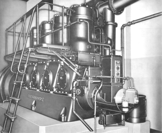
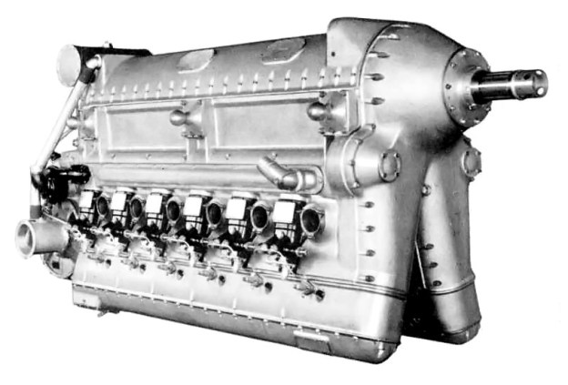
Deschamps V 3050 inverted V-12 aircraft diesel engine of 1934.

The Deschamps V 3050 was an inverted, 12-cylinder, diesel aircraft engine of all aluminum construction. The engine was built by the Lambert Engine and Machine Company in Moline, Illinois and completed in 1934. The cylinder banks were arranged in a 30-degree Vee to minimize the engine’s frontal area. With a 6.0 in (152 mm) bore and 9.0 in (229 mm) stroke, the engine had a total displacement of 3,053 cu in (50.0 L). The liquid-cooled, direct drive engine produced 1,200 hp (895 kW) at 1,600 rpm for takeoff and 950 hp (708 kW) at 1,500 rpm for cruise. Fuel consumption was 0.41 lb/hp/hr (249 g/kW/h). When built, it was one of the largest and most powerful diesel aircraft engines in the world.

The compression ratio of the V 3050 was 16 to 1, and air was forced into the cylinders by two gear-driven GE superchargers. The centrifugal superchargers were driven at 13.5 times crankshaft speed (21,600 rpm) and provided air at 12 psi (0.83 bar). Cylinder scavenging for the two-stroke cycle required eight psi, leaving four psi for boost. A small portion of the air entering the superchargers was taken from the crankcase to provide ample ventilation and burn away any fuel vapors. Sea-level power could be maintained to an altitude of 10,000 ft (3,048 m).

Each bank of cylinders had an intake manifold on the inside of the Vee to deliver air from the superchargers to the cylinders. The compressed air entered each cylinder via two poppet valves actuated simultaneously by an overhead camshaft driven at crankshaft speed.

Rear view for the Deschamps diesel highlighting the two GE superchargers. The glow plugs are also visible on the right cylinder bank.

A ring of 12 exhaust ports was located in the cylinder wall and exposed by the piston. To prevent excessive oil consumption and exhaust smoke, a small horizontal groove was cut in the cylinder wall just below each of the 12 exhaust ports. The grooves in the cylinder liner aligned with an annular groove in the cylinder casing wall. The annular grooves for all 12 cylinders were connected to a vacuum pump that scavenged oil from the pistons. The amount of oil stripped from the pistons was controlled by the amount of vacuum.

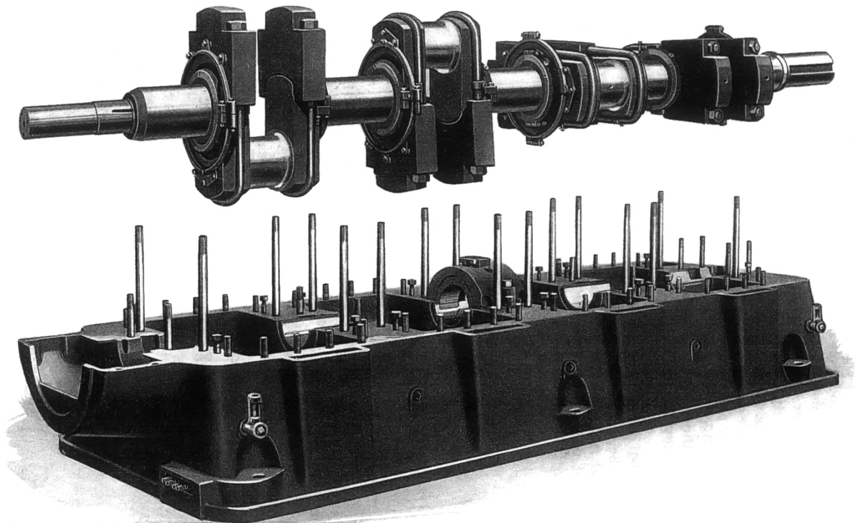
The superchargers and camshafts were driven from the crankshaft via separate vertical shafts with bevel gears. A Lanchester type torsional vibration damper was incorporated on the rear of the crankshaft to protect the gear drives. The damper was combined with a torque limiter clutch that would slip momentarily under sudden changes in torque.

Each bank of cylinders had independent intake delivery, exhaust, liquid-cooling connections, oil connections, oil and fuel pumps, and fuel injectors. In theory, each bank could be operated independently of the other bank, sharing only a common crankshaft. At 1,600 rpm, oil was circulated at 80–100 psi (5.5–6.9 bar) while coolant circulation was at 230 gpm (871 l/m).

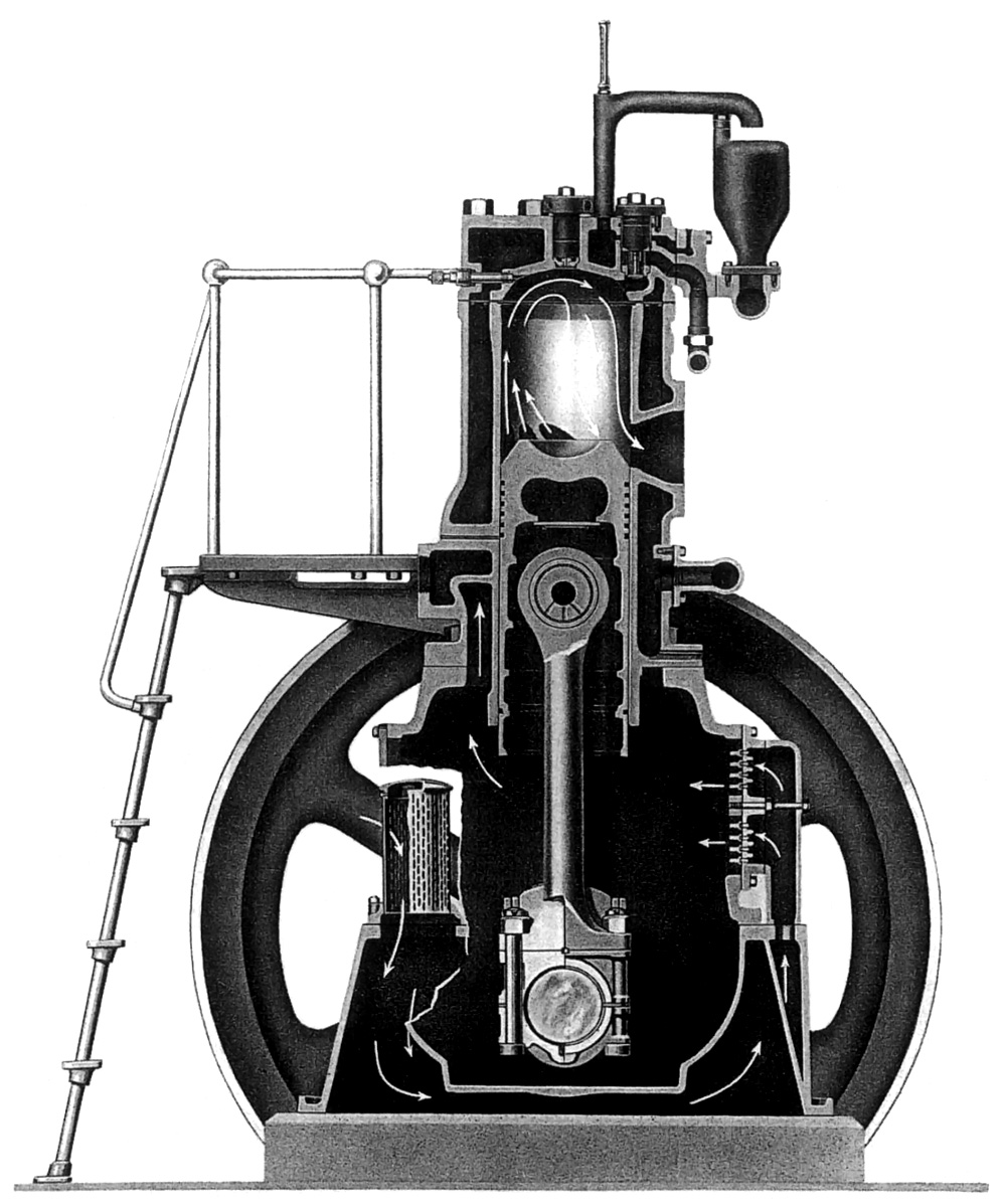
Sectional view of the Deschamps V 3050 diesel with the glow plug detailed on the lower left.

Fuel was injected directly into each cylinder via two Deschamps-designed (U.S. patent 2,020,302) fuel injectors operating at 3,500 psi (241.3 bar). The two injectors per cylinder alternated supplying fuel into the cylinder, each firing every-other compression stroke. For slow rpm operation, one injector was shut off, essentially making the engine a four-stroke. This kept the engine running smoothly and the cylinders warm for instant application of more power. One fuel pump for each engine bank was used and supplied fuel at 15 psi (1.0 bar) with a maximum flow of 150 gph (9.4 l/m).

The engine was air-started by a compressor charged to 850 psi (58.6 bar). For staring the engine in cold weather, glow plugs were provided in the right cylinder bank while the left bank’s intake valves were kept open with the fuel shut off. A reversing gear could be fitted for utilizing the engine in airships. The V 3050 was 26.5 in (0.67 m) wide, 49.5 in (1.26 m) tall, and 99 in (2.52 m) long. It weighed 2,400 lb (1,089 kg) with all accessories, giving it 2.0 lb/hp (1.2 kg/kW).

After completing the engine, no funds remained for testing. Deschamps met with the Army Air Corps Power Plant Laboratory in June 1934, but it seems no further testing was done on the engine. Deschamps went on to work for various aviation corporations, patenting a number of fuel injectors and pumps along the way. Amazingly, the Deschamps V 3050 diesel engine survives and is in storage at the National Air and Space Museum’s Garber Facility in Silver Hill, Maryland.

Deschamps Diesel in storage at the National Air and Space Museum’s Garber Facility in Silver Hill, Maryland. (Fred van der Horst image via the Aircraft Engine Historical Society)

Sources:
Aircraft Diesels by Paul H. Wilkinson (1940)
Aerosphere 1939 by Glenn Angle (1940)
Diesel Aviation Engines by Paul H. Wilkinson (1942)
Jane’s All the World’s Aircraft 1934 by C. G. Grey (1934)
– “A 1,200 H.P. Diesel Engine.” Flight. May 24, 1934
– “Internal Combustion Engine” U.S. Patent 2,064,196 by Desire J. Deschamps (1930) pdf

McDonnell Aircraft Corporation Model 1

By William Pearce

In 1938 James McDonnell found himself diligently at work with the Glenn L. Martin Company in Baltimore, Maryland. While employed with Martin, McDonnell had designed a number of successful aircraft and was now focused on a streamlined design with the engine mounted in the fuselage. McDonnell had worked for the Martin Company since 1933 but was very interested in starting his own aircraft company. Late in 1938, he left Martin.

Artwork of the McDonnell Model 1 with a four-gun nose.

The McDonnell Aircraft Corporation was incorporated on 6 July 1939. The company began work out of St. Louis, Missouri and quickly obtained subcontracted work for other aircraft manufacturers. In addition, McDonnell submitted a few aircraft proposals to the United States Army Air Corps and Navy. Although none of the proposals led to any contracts, they did open the door for McDonnell to be included in the Air Corps Request for Data R40-C, officially issued on 20 February 1940.

R40-C was an informal Request for Data that encouraged aircraft manufacturers to propose unorthodox aircraft. These aircraft would need to be capable of at least 450 mph (724 km/h), but preferably 525 mph (845 km/h), and meet other requirements outlined in Type Specification XC-622. R40-C asked aircraft engine manufacturers to develop new power plants. A total of 26 aircraft designs were submitted by six selected aircraft companies. These designs included a mix of eight different engines from four engine companies. An additional engine from an additional manufacturer was later added.

Three-view general arrangement drawing of McDonnell’s Model 1 from November 1939. The drawing seems to illustrate a five-gun nose: two machine guns housed in the fuselage sides, two more (or cannons) toward the nose, and one cannon (possibly 37 mm) in the center of the nose.

McDonnell’s answer to R40-C was the Model 1 (often called Model I). It was the company’s first design, and McDonnell submitted its proposal to the Air Corps on 11 April 1940. Four Model 1 variations were submitted that differed only by engine type. While the Model 1 design appeared fairly conventional, it was possibly the most radical of the designs submitted. The Model 1’s shape was a direct evolution of concepts James McDonnell was working on during his last days with the Martin Company.

The Model 1 featured unprecedented streamlining and incorporated airfoil-shaped fillets where the wing and fuselage joined. The proposed engines were the 24-cylinder Allison V-3420-B2, 24-cylinder Pratt & Whitney H-3130, 24-cylinder Pratt & Whitney X-1800-A2G, and 42-cylinder Wright R-2160 Tornado; all were liquid-cooled. Regardless of the type selected, the engine was buried in the fuselage aft of the pilot. Engine power was transmitted via extension shafts and right angle gear drives to a pair of two-speed, four-blade, 10 ft 7 in (3.23 m) diameter, pusher propellers mounted on the wings. The aircraft featured gear-driven radiator cooling fans. Originally the aircraft was to be armed with two .30-cal. machine guns and two 20 mm cannons, but armament varied throughout the design process. However, armament always consisted of a combination of two to four machine guns and one to four cannons.

Allison V-3420-powered McDonnell Model 1 cutaway dated April 3, 1940. Armament now includes six guns: two machine guns in the fuselage sides, two more (or 20 mm cannons) toward the nose, and two 20 mm cannons in the nose.

The X-1800 and R-2160-powered designs did not meet the specifications of XC-622 and were dropped from the R40-C competition.  With a two-stage supercharger for the V-3420 engine and a two-stage, two-speed supercharger for the H-3130, both engines provided sufficient power for their respective Model 1 designs to achieve the XC-622 specifications.

The Model 1 had a 45 ft (13.7 m) wingspan and was 45 ft 4 in (13.8 m) long. With the Allison V-3420, the aircraft weighed 13,826 lb (6,271 kg) and had a maximum speed of 383 mph (616 km/h) at 5,000 ft (1,524 m) and 448 mph (721 km/h) at 20,000 ft (6,096 m). With the Pratt & Whitney H-3130, the Model 1 weighed 14,800 lb (6,713 kg) and had a maximum speed of 385 mph (620 km/h) at 5,000 ft (1,524 m) and 454 mph (731 km/h) at 20,000 ft (6,096 m).

mcdonnell-model-1-tractor-flaps

This wind tunnel model illustrates the evolution of the Model 1 as it became the XP-67. Seen here is the Model 2, with wing-mounted Continental XI-1430 engines in a tractor configuration. The basic shape of the Model 1’s fuselage and wings remained unchanged. The next version, known as the Model 2A, incorporated significant blending of the fuselage and engine nacelles with the wings. The Model 2A was the final step to the XP-67. (Image is flipped as the model was actually hung inverted in the wind tunnel.)

It would take an estimated 42 months to develop the engine and power drives for the Model 1. In addition, the Model 1 was the heaviest aircraft in the competition. These and other factors resulted in the two remaining Model 1 proposals to be ranked 21st and 22nd out of 26 submissions. Even so, the Model 1 did interest the Air Corps enough for them to purchase engineering data and a wind tunnel model on 6 June 1940 for $3,000. This was the McDonnell Aircraft Corporation’s first sale to the Army Air Corps.

The new engines involved with the R40-C competition became known as the “hyper” engines, an abbreviation of high-performance. The aircraft that won the competition were the Vultee XP-54 Swoose Goose, Curtiss XP-55 Ascender, and Northrop XP-56 Black Bullet. All were built and were pusher designs that failed to meet expectations and were fraught with technical difficulties. None of the hyper engines or R40-C aircraft entered production. The Model 1 was developed into the McDonnell XP-67 Moonbat that, although not successful, was built and did fly.

McDonnell Aircraft Corporation ad featuring the Model 1.

Sources:
American Secret Pusher Fighters of World War II by Gerald Balzar (2008)
McDonnell Douglas Aircraft Since 1920: Volume II by Rene Francillion (1990)
American Secret Projects 1937–1945 by Tony Buttler and Alan Griffith (2015)
– “Design for a Pursuit Airplane” U.S. Design Patent 134,425 by James McDonnell (1942) pdf

Papin-Rouilly Gyroptere (Gyropter)

By William Pearce

The Papin-Rouilly Gyroptere as depicted on the cover of the September 1922 edition of Popular Science.

The Gyroptere was designed in France from 1911-1914 by Alphonse Papin and Didier Rouilly. Their monocopter was based on the sycamore seed; a single blade extends from the seed to spin the seed and slow its descent as it falls. Though unsuccessful, the machine was the first air-jet helicopter. Papin and Rouilly obtained French patents 440,593 and 440,594 for their invention and later obtained U.S. patent 1,133,660 in 1915 (filed in 1912).

Construction of Papin and Rouilly’s Gyroptere began in February 1914 and was completed in June of the same year. The prototype was named Chrysalis (Chrysalide). Constructed of molded wood, the Gyroptere was well built with compound curves and a smooth sweep of its single, long, airfoil-shaped blade. The fabric-covered blade was hollow and approximately 19.5 ft (5.9 m) long and 4.4 ft (1.33 m) wide, giving it an area of 130 sq ft (12 sq m). The blade was counterbalanced by an 80 hp (60 kW), nine-cylinder Le Rhone rotary engine. The pilot occupied a nacelle between the blade and engine. The bottom of the nacelle included a structure to support the machine while it was on the ground or act as a float when on water.

The Le Rhone engine was started with a pulley system. The engine, turning at 1,200 rpm, drove a fan that produced an output of just over 250 cu ft (7 cu m) of air per second. The air, along with the engine’s hot exhaust for thermal expansion, was directed through the length of the blade and exited the blade’s tip through a nozzle on the trailing edge at 330 ft/s (100 m/s). This jet of air would turn the blade, and the gyroscopic force of the motor would lift the blade into a positive angle of attack. The nacelle that carried the pilot was centered on the axis of rotation. The nacelle was mounted on ball-bearings and was centered against four horizontal rollers. The entire machine weighed 1,100 lb (500 kg), which was 220 lb (100 kg) more than originally planned.

This image offers a good view of the Gyroptere. The blade does not have its covering, the float and directional control tube can clearly be seen in the center nacelle, and the Le Rhone engine in its fan housing is on the right.

The pilot controlled the Gyroptere through the use of two foot pedals: one pedal opened a valve to admit air to the blade; and the second pedal allowed air into an L-shaped tube above the craft that served as a rudder for directional control. The L-shaped tube was directed by the pilot; its discharge provided forward thrust, steering, and stabilized the center drum to prevent it from spinning with the blade. A switch in the nacelle allowed the pilot to engaged or disengaged the engine.

This view highlights the air-jet nozzle on the trailing edge of the blade, which can be seen on the left.

The outbreak of World War I delayed testing until 31 March 1915. During tests on Lake Cercey (Reservoir de Cercey), near Pouilly-en-Auxois, France, the craft achieved a rotor speed of only 47 rpm, well below the 60 rpm calculated as necessary for liftoff. Even so, the machine was wildly out of balance, and the blade repeatedly contacted the water, damaging itself and shaking up the pilot. In addition, the Le Rhone engine used was not powerful enough; the Gyroptere had been designed to use a 100 hp (75 kW) engine which could not be obtained.

A military commission observing the test determined that such a machine could not aid the war effort and halted further evaluation. The Gyroptere remained at Lake Cercey until it was sold for scrap in 1919.

The completed Gyroptere awaiting tests on Lake Cercey on 31 March 1915.

Sources:
French Aircraft of the First World War by Davilla and Soltan (1997)
– “Helicopter” U.S. Patent 1,133,660 by Papin and Rouilly (1915) pdf
http://fr.wikipedia.org/wiki/Gyropt%C3%A8re
http://en.wikipedia.org/wiki/Monocopter
http://flyingmachines.ru/Site2/Crafts/Craft29386.htm
– “Will This ‘Whirling Leaf’ Flying Machine Solve Greatest Problem in Aviation?Popular Science (September 1922)

Sikorsky S-56 (CH-37 Mojave/Deuce) Helicopter

By William Pearce

At the time of its introduction, the Sikorsky S-56 was the largest and fastest military helicopter in the Western world. In 1956, the helicopter set two height-with-payload world records and one world speed record. The S-56 was also Sikorsky’s first multi-engined helicopter and remains the largest piston-engined helicopter ever built.

CH-37B Mojave in flight. The screen on the side of the engine nacelle to maximize engine cooling is visible.

The S-56 was powered by two Pratt & Whitney R-2800 air-cooled radial engines with a takeoff rating of 2,100 hp (1,566 kW) and a cruise rating of 1,900 hp (1,417 kW). R-2800-50 engines were initially used, but late production aircraft used R-2800-54 engines, which had upgraded magnetos and additional mounting studs. The engines were connected to the main rotor’s transmission via a hydro-mechanical clutch. This clutch allowed the engines to run independently from the main rotor for starting or in the event of an engine failure. Power for the tail rotor was taken off the main transmission.

Unlike most heavy lift helicopters, the engines were not located in the upper section of the fuselage. Instead, each engine was housed in a nacelle fixed to the end of a short shoulder-mounted wing on each side of the helicopter. The engine nacelles also accommodated the machine’s fully retractable, twin-wheeled main landing gear.

The S-56’s engine arrangement allowed for an unobstructed cargo bay of nearly 1,500 cubic feet (24.5 cu m)—large enough to carry three Jeeps, 24 stretchers, or up to 26 fully-equipped troops. The cargo bay measured 30 ft 4 in (9.2 m) long, 7 ft 8 in (2.3 m) wide and 6 ft 8 in (2.0 m) high. The S-56’s nose section was equipped with large clam-shell doors which allowed vehicles to be driven straight into the cargo area. The cockpit was placed above and slightly aft of the doors to ensure good visibility. The single main rotor was five-bladed and designed to sustain the aircraft in flight with one blade shot away in combat. For storage, the helicopter’s main rotor blades folded back along the fuselage and the tail rotor mast folded forward.

Head on shot of the CH-37 with the clam-shell doors open and distinctive engine pods visible.

Sikorsky originally developed the Model S-56 in response to a 1950 Marine Corps requirement for a heavy-lift assault transport able to carry 26 fully equipped troops. In 1951 the Navy ordered four XHR2S-1 prototypes for USMC evaluation, and the first of these made its maiden flight on 18 December 1953. In 1954 the Army borrowed one of these pre-production machines. Re-designated YH-37 Mojave, it was subjected to rigorous evaluations before it was returned to the Marines.

Based on the helicopter’s excellent showing during the Marine and Army evaluations, Sikorsky was awarded a contract for 55 HR2S-1 for the Marines, who nicknamed the helicopter Deuce, and 94 H-37A Mojaves for the Army. The H-37A was delivered to the Army during the summer of 1956, at about the same time the HR2S-1 naval variant was entering regular Marine squadron service. The Marines set three world records for helicopters in November 1956 when a HR2S-1 carried an 11,050 lb (5,012 kg) payload to an altitude of 12,000 ft (3,658 m), carried 13,250 lb (6,010 kg) to over 7,000 ft (2,134 m), and set a three kilometer speed record of 162.743 mph (261.910 km/h). All aircraft were delivered to their respective services by May 1960.

In 1961 Sikorsky began converting the Army’s H-37As to B model standards. The upgrade included the installation of automatic flight stabilization systems that gave the H-37B the ability to load and unload while hovering, crash-resistant fuel cells, and modified nose doors. All but four A models were eventually converted. In 1962 military aircraft designations in the United States were unified, and the H-37A were re-designated CH-37A; the modified B machines became CH-37B, and the Marine’s HR2S-1 became CH-37C.

Three CH-37C Deuces on a carrier deck. The hole on the front of the engine nacelles is the air intake for the R-2800 engine.

The S-56 was developed just prior to the widespread adoption of the turbine engine as a helicopter powerplant. As a result, the type was forced to rely on larger, heavier, and less powerful piston engines. Even so, the S-56 ultimately proved to be a more than capable heavy-lifter. In June 1963, four CH-37B Mojaves were temporarily deployed to Vietnam to recover downed U.S. aircraft. By the following December, the Mojaves had recovered an estimated $7.5 million worth of equipment. Most of the recoveries were sling-lifted out of enemy-held territory that was virtually inaccessible by any other means.

In September 1965 a Marine detachment of eight Deuces was sent to Vietnam for general transport duties in support of Marine Air Group 16 at Marble Mountain. Although this detachment had only ten pilots for eight aircraft, they flew about 5,400 hours in 1,500 missions, hauled more than 12.5 million pounds (5.67 million kg) of cargo, and transported some 31,000 passengers without an air accident.

The Mojave did not see more extensive service in Vietnam primarily because of its replacement by the turbine-powered Sikorsky CH-54 Tarhe (S-64 Skycrane), a machine that weighed slightly less than the CH-37 but could carry nearly four times as many troops or five times as much cargo. In addition, the R-2800 engine was very loud, created a lot of vibration, and required much more maintenance than a turbine engine. The last CH-37 was withdrawn from Army service in the late 1960s. The Marine’s Deuces were replaced by CH-53 Sea Stallions in 1967.

When built, no helicopter could surpass the CH-37’s lift capacity.

Sources:
U.S. Army Aircraft Since 1947 by Stephen Harding (1997)
R-2800: Pratt & Whitney’s Dependable Masterpiece by Graham White (2001)
http://en.wikipedia.org/wiki/Sikorsky_CH-37_Mojave
http://www.aviastar.org/helicopters_eng/sik_s-56.php
http://www.popasmoke.com/notam2/showthread.php?1489-CH-37C-Deuce-A-History

Douglas XA-26D 41-39543

Douglas XA-26D and XA-26E Invaders

By William Pearce

The Douglas XA-26D and E were improved versions of the Douglas A-26B and C respectively. Both the XA-26D and E were upgraded with a more powerful version of the Pratt & Whitney R-2800 radial engine, the -83, built by Chevrolet and rated at 2,100 hp (1,566 kW). The engine’s output increased to 2,400 hp (1,780 kW) with water injection. The carburetor air scoops in the cowling were revised along with the carburetors, superchargers, engine mounts, and generators. The aircraft were fitted with wide-cord, 12.7 ft (3.87 m), four-blade propellers with spinners, although three-blade propellers were also tested. The top speed of the XA-26D and E was 403 mph (649 km/h) at 15,000 ft (4,572 m)—about 50 mph (80 km/h) faster than the B and C models—and the climb rate doubled to 2,326 fpm (11.8 m/s).

Douglas XA-26D 41-39543

The second XA-26D Invader, serial number 41-39543, is seen here with three-blade propellers. Note the spinners and revised engine cowlings compared to a typical A-26.

The D model was a solid nose version primarily intended for ground attack. The aircraft was equipped with 14 forward-firing .50-cal. machine guns: eight in the nose and six more in the wings. The aircraft also had dorsal and ventral barbettes with two machine guns each.

The first XA-26D Invader was modified from an A-26B, serial number 44-34100, starting in January 1945. Serial number 44-34100 was accepted by the USAAF on 31 January 1945 but was not available until 31 October 1945. The individual aircraft record card has a notation indicating the aircraft was to remain at the contractor’s plant for 180 days. The first record entry listing the aircraft as an A-26D was on 11 November 1945. Another XA-26D was created using A-26B serial number 41-39543, and the D modifications were completed by July 1945.

Some sources list another A-26B, serial number 44-34776, as being converted to the XA-26D standard. However, the data card for this aircraft makes no reference to a conversion program.

One B-26C, serial number 44-35563, was modified by the Douglas plant to XA-26E specifications. The E model was the glass nose version with two machine guns in the nose, six in the wings, and two in each dorsal and ventral barbettes.

A contract for 750 production A-26Ds was placed on 13 April 1945, following an order of 1,250 A-26Es placed on 5 April 1945. Both contracts were cancelled at the end of World War II; none of the aircraft were built.

Douglas XA-26D 41-39543 4-blade

The second XA-26D aircraft with four-blade propellers. Note the first Douglas XB-42 Mixmaster prototype at left in the background.

Sources:
American Bomber Aircraft Development in World War 2 by Bill Norton (2012)
http://www.nationalmuseum.af.mil/factsheets/factsheet.asp?id=3067
http://www.nationalmuseum.af.mil/factsheets/factsheet.asp?id=3149

NA-98X Front

North American Aviation NA-98X Super Strafer

By William Pearce

In 1943, North American Aviation (NAA) created an internal design for an improved attack bomber that would provide the firepower of the B-25H but with substantially improved performance. This evolution of the B-25 line was intended as an alternative to the heavily-armed and delayed Douglas A-26B Invader. Power was to be provided by a pair of Pratt & Whitney R-2800 air-cooled radial engines housed inside low-drag cowlings and driving a pair of cuffed, four-blade propellers with spinners. The empennage was changed to a conventional single-tail, altering one of the B-25’s most notable characteristics. The wing tips were square-cut like a P-51’s, rather than rounded, permitting the ailerons to be extended farther outboard to provide better roll control. Armament improvements were to include a computing gun sight and a new low-drag canopy designed by North American for the top turret. A compensating sight was to be used in the tail turret and illuminated reflector optical sights for the waist guns. Otherwise, the aircraft had the same armament as the B-25H, including the 75mm cannon.

NAA B-25 based high performance attack bomber drawn by Eugene Clay.

In early 1944, a low-cost and less ambitious alternative was submitted to the Army Air Forces. This proposal was to take the existing B-25 airframe and apply many of the enhancements from the NAA internal design. A B-25H-5 (serial number 43-4406) was chosen as a testbed for the modifications, which no longer included the single tail and four-blade propellers. It was given the designation NA-98X by NAA and nicknamed Super Strafer. Since it was not designed for any USAAF requirement, it never carried an official USAAF designation.

The new aircraft was powered by a pair of 2,000 hp (1,491 kW) Pratt & Whitney R-2800-51 engines with 15 minutes of water injection, all housed in A-26 cowlings. Large conical spinners were used on the three-blade propellers. The squared wing tips allowed the ailerons to be extended by one foot, and the control system was changed to lighten the stick forces. Except for the removal of the fuselage blister gun packs, the aircraft had the same armament as the B-25H.

The NA-98X: a B-25H, serial number 43-4406, modified with R-2800 engines, spinners, and squared wings.

The first flight of the NA-98X took place at Mines Field in Los Angeles on 31 March 1944. NAA test pilot Joe Barton was at the controls with Jim Talman as the NAA flight engineer. The flight lasted an hour, and Barton reported better speed and acceleration, reduced vibration, and a higher roll rate compared to a standard B-25. The Super Strafer performed well. The aircraft reached 10,000 feet (3,048 m) in 4.9 minutes at war emergency power and in 5.3 minutes at military power. A maximum speed of 328 mph (528 km/h) was achieved at sea level with war emergency power, and Barton eventually achieved 350 mph (563 km/h) at a higher altitude. The performance numbers were a drastic improvement over the standard B-25H’s top speed of 273 mph (439 km/h) and 790 fpm (4.0 m/s) climb rate. There were 16 more NAA test flights before the aircraft was turned over to the USAAF for evaluation.

The increased power of the R-2800 engines, along with the increased aileron area and reduced stick forces, created the possibility to operate the aircraft outside the structural limits of the wings. This could lead to a catastrophic failure, loss of the aircraft, and possible loss of life. Without strengthening the wings for intended dives of 400 mph (644 km/h) and high-g pullouts, the maximum airspeed was restricted to 340 mph (547 km/h), and a g-limit of 2.67g was imposed during flight tests.

NAA NA-98X cowling

A detailed look at the A-26 cowling covering the R-2800 engine installed on the NX-98X.

Major Perry Ritchie was assigned as the evaluator for the USAAF and had made 13 flights in the aircraft before disaster struck on 24 April 1944. Returning from the aircraft’s 29th test flight, Maj. Ritchie and Lt. Winton Wey approached Mines Field at a very high speed, above the 340 mph (547 km/h) redline. As he made a steep pull-up, in excess of the 2.67g restriction, both wings separated outboard the engine nacelles and struck the horizontal stabilizers, causing the tail to break free from the aircraft. The NA-98X crashed, killing both Maj. Ritchie and Lt. Wey.

The NA-98X was a very powerful and responsive aircraft. Maj. Ritchie was primarily a fighter pilot and had a tendency to fly the maneuverable bomber more like a fighter. Maj Ritchie had made the high-speed pass and abrupt pull-up twice before and was warned not to do it again. Some eyewitnesses estimated that the NX-98X made the last pass at around 400 mph (644 km/h) and hit around 5g in the pull-up. Simply put, the aircraft was flown beyond its known structural limitations by Maj. Ritchie.

Following the crash, all further work on the NA-98X project was abandoned even though the RAF had shown interest after a test flight. Admittedly, the wings would have required a redesign to cope with the power from the R-2800s, negating any cost savings for performance on par with the Douglas A-26. In its short 25-day life, the NA-98X Super Strafer totaled 40:15 hours of flight tests. NAA time totaled 21:25 hours over a period of 22 days, including eight days of down time. Total time for Maj. Ritchie was 18:50 hours over a period of three days.

NA-98X Front

Front view of the NA-98X Super Strafer with the 75mm cannon and squared wingtips clearly visible.

Sources:
– “North American B-25 Variant BriefingWings of Fame Volume 3  (1996)
American Bomber Aircraft Development in World War 2 by Bill Norton (2012)
North American Aircraft 1934-1998 Volume 1 by Tom Avery (1998)
http://www.joebaugher.com/usaf_bombers/b25_16.html
http://www.warbirdinformationexchange.org/phpBB3/viewtopic.php?t=31406&view=previous

Monaco-Trossi1935 Wiki

Monaco Trossi 1935 Grand Prix Racer

By William Pearce

One of the oddest Grand Prix race cars ever built was the 1935 Monaco Trossi. Built by Augusto Camillo Pietro Monaco and funded by race driver Count Carlo Felice Trossi, the 1935 Monaco Trossi was a front-wheel drive car powered by an air cooled, 16-cylinder, two-stroke radial engine.

Augusto Monaco had built a successful racing car / hill climber but had aspirations of building a Grand Prix car for the 750 kg (1,653 lb) Grand Prix racing formula. For the Grand Prix car, Monaco joined forces with an engineer/driver named Giulio Aymini. The team also received support from Senator Agnelli at FIAT, who offered FIAT’s Lingotto facilities, in Turin, to build and test the new two-stroke radial engine. However, once the engine was built, tests revealed so many problems that Agnelli and FIAT withdrew their support, leaving Monaco in search of new financial and manufacturing assistance.

A vintage shot of the Monaco Trossi at Monza. With the cowling removed to aid cooling, a good view is provided of the engine and its paired cylinders.

Monaco convinced race driver Count Felice Trossi, who was a successful member of the Alfa Romeo team, to become a partner in the project providing financial and manufacturing support. The car was built in Trossi’s workshop, which was part of the Gaglianico castle outside Biella in northern Italy. A friend of Trossi, Count Revelli, helped design a streamlined body for the car. Many rumors and much speculation surrounded the racer, and it was finally revealed to the public at the Autodromo Nazional Monza in July 1935 for tests and qualifying sessions in preparation for the Italian Gran Prix.

The air cooled, 16-cylinder, two-stroke radial engine was mounted at the very front of the car. With a 65 mm (2.56 in) bore and 75 mm (2.96 in) stroke, the engine displaced 3,982 cc (243 cu in). The cylinders were arranged in two rows of eight with each front row cylinder and rear row cylinder paired together. While having two cylinders and two pistons, each cylinder pair had a common combustion chamber and spark plug. The eight two-cylinder pairs were positioned around the crankcase. Being a two-stroke engine, there were no intake or exhaust valves. The inlet ports were in the rear cylinders and exhaust ports were in the front cylinders. The crankshaft was a three-piece design and the crankcase was made of duralumin. For both cylinder rows, the connecting rods were of the normal radial engine type with one master rod connected to the crankshaft and the seven articulating rods connected to the master rod.

Rare view of the Monaco Trossi under its own power at Monza in 1935.

Behind the engine were two Zoller M 160 superchargers providing a pressure of 0.68 atm (10 psi), each supplied by a Zenith carburetor. Exhaust gases discharged into two four-pipe manifolds on the front of the engine. These manifolds led to two long exhaust pipes that extended under the car and exited behind the rear wheels. The engine produced 250 hp (186 kW) at 6,000 rpm.

Power from the engine was transferred to the four-speed transmission by a shaft that went through the transmission to the clutch, then back into the transmission. The independent suspension for each wheel was provided by double wishbones, horizontal coil springs, and cockpit adjustable oil dampers. The aircraft-type spaceframe chassis was made with 4 cm (1.57 in) diameter manganese-molybdenum steel tubes with larger cross tubes at the front and rear. The lightweight alloy body panels were screw-fastened to the chassis. The car featured large hydraulic drum brakes on each wheel, which was advanced for the time. Front tires were 5.25 x 31 and rear tires were 4.40 x 27. The vehicle weighed about 710 kg (1,565 lb).

Monaco-Trossi1935 Wiki

A clear view of the two four-pipe manifolds taking the exhaust to the rear of the car. Also note the spark plugs extending out of the engine cowl. (Image by Brain Snelson via Flickr/Wikimedia Commons)

Both Aymini and Trossi tested the car at Monza reaching speeds of 240 km/h (150 mph), and the car was on the entry list for the 1935 Italian Grand Prix. However, testing revealed that the car experienced severe overheating and a tendency for the engine to destroy the spark plugs. But the more serious issue was the extreme understeer caused by the 75% front / 25% rear weight distribution. With the problems uncorrectable without a serious redesign, the car proved too dangerous and it was never raced.

After Count Trossi’s death in 1949, the 1935 Monaco Trossi racer was donated by his widow, the Contessa Lisetta, to the Museo dell’Automobile in Turin where it is currently on display.

Monaco-Trossi_1935_Racer

This view clearly illustrates the Monaco Trossi’s front end complexity. (Image by Brain Snelson via Flickr/Wikimedia Commons)

Sources:
http://www.kolumbus.fi/leif.snellman/c8b.htm
http://www.omniauto.it/magazine/6016/monaco-trossi-laereo-senza-ali
http://jalopnik.com/383661/1935-monaco-trossi-is-16-cylinders-of-radial-engine-awesome

Fairbanks-Morse 32-14 engine

Fairbanks Morse Model 32 Stationary Engine

By William Pearce

In 1823, Thaddeus Fairbanks and his brother Erastus founded the E & T Fairbanks Company, which operated an iron foundry. In June 1832, Thaddeus patented the platform scale which quickly became the mainstay of the company. Back then, scales were integral to business as marine and railway shippers charged by weight. The E & T Fairbanks Company became the leading scale manufacturer in the United States and sold thousands of scales in the US, Europe, South America, and China.

Fairbanks-Morse 32-14 engine

Four-cylinder Fairbanks Morse 32E-14 engine.

In the 1870s, Charles Morse, an E & T Fairbanks Company distributor, was responsible for adding Eclipse Windmills and pumps to the E & T Fairbanks Company product list. Morse’s successful sales abilities enabled to him becoming a partner, and the company was eventually renamed Fairbanks Morse & Company.

In the late nineteenth century, Fairbanks Morse & Company continued to expand its now very diverse product line. The Company began producing oil and naptha engines in the 1890s. The Fairbanks Morse gas engine became a success providing power for irrigation, electricity generation, and oilfield work. Small power plants built by Fairbanks Morse were popular and evolved by burning kerosene in 1893, coal gas in 1905, and semi-diesel in 1913.

After the expiration of Rudolf Diesel’s American license in 1912, Fairbanks Morse entered the large engine business. Introduced in 1914, the company’s large Model Y semi-diesel stationary engine became a standard workhorse used by sugar, rice, and timber mills; mines, and other applications. The Model Y was available in sizes from one through six-cylinders, or 30 to 200 horsepower (22 to 149 kW).

Fairbanks-Morse 32E cutaway

Sectional view of a Fairbanks Morse 32E-14 engine illustrating the induction and exhaust.

Successor to the Model Y, the Y-VA engine was developed in Beloit, Wisconsin and introduced in 1924. It was the first high compression, cold start, full diesel developed by Fairbanks Morse without the acquisition of any foreign patent. The Y and Y-VA engines were made to run for long periods without stopping. By 1925 there were over 1,000 American cities generating electricity with Fairbanks Morse engines.

Around 1925 the Y-VA diesel was improved and renamed the Model 32 engine. The Model 32 was the culmination of many years of improvement upon the initial Model Y design. The improvements included various cylinder head designs, increased compression, and the eventual adoption of high-pressure injection and differential fuel injectors. To differentiate various cylinder heads and methods of induction on the Model 32 engine series, letter designations A thru E were used.

Fairbanks-Morse 32E crankshaft

The crankshaft and lower base for a four-cylinder 32E engine. The base for the individual cylinders mounted directly to the lower base.

The Model 32 was available in two cylinder sizes: 12 in (305 mm) bore with a 15 in (381 mm) stroke and 14 in (356 mm) bore with 17 in (432 mm) stroke. The 12×15 engine, known as -12, was available in one- through three-cylinder versions with each cylinder displacing 1,696 cu in (27.8 L) and producing about 40–50 hp (30–37 kW). The 14×17 engine, known as -14, was available in one- through six-cylinder versions with each cylinder displacing 2,617 cu in (42.9 L) and producing 60–75 hp (45–56 kW). Normal operating speed ranged from 257 to 360 rpm.

The two-stroke, water-cooled diesel of all cast iron construction was air started with 250 psi (17.2 bar). The only moving parts in the Model 32 were the pistons, connecting rods, crankshaft, oil pumps, fuel pumps, flywheel, and governor. The engine had no intake or exhaust valves. Air was drawn through the crankcase and into the cylinder when the piston uncovered an induction port. The air was then compressed by the piston as fuel was injected into the cylinder at 2,000 psi (137.9 bar) and ignited by the heat of the 500 psi (34.5 bar) compression. As the piston moved down on the power stroke, it uncovered the exhaust port, allowing the burnt gases to be expelled. Fuel consumption was around 0.39 lb/hp/hr (237 g/kW/h).

Fairbanks Morse Model 32E piston sectional, piston, and connecting rod assembly.

The Model 32 engines were in service for years in power stations, manufacturing plants, ice plants, flour mills, rock crushing plants, cotton gins, seed oil mills, textile mills, irrigation and drainage pumping stations, and many other locations. To give some idea of the service life of the engine, at 10,000 hours of operation the needle rollers on the piston pin should be replaced. At 20,000 hours the needle rollers should be replaced again and the piston pin should be rotated 180 degrees. At 40,000 hours, or 4.57 years of continuous operation, the piston pin and bushing should be replaced. The Model 32 was built at least into the 1940s. A number of engines were still in regular service at various locations into the 1970s, with at least one being run until 1991. The Indian Grave Drainage District in Quincy, Illinois still has three operational Model 32 engines, and three engines are on standby as back-up power generators in Delta, Colorado.

Today, stationary diesels are still used for power generation, pumping, and other purposes. Fairbanks Morse still exists in this field and also manufactures marine and locomotive diesels. As far as the Model 32 is concerned, some still exist in abandoned factories and power stations, while others have been saved and preserved. A few Model 32s are run for special events, enabling them to shake the ground once again.

Here is a video of 1936 four-cylinder Fairbanks Morse 32D-14 by accessgainer8. This engine is owned and occasionally operated by the Pottsville Historical Museum near Grant’s Pass, Oregon. The engine weighs around 60,000 lb (27,216 kg), and the flywheel alone weighs about 12,000 lb (5,443 kg).

Sources:
Fairbanks Morse: 100 Years of Engine Technology by C. H. Wendel (1993)
https://old.oldtacomamarine.com/fairbanks/manual.html
https://en.wikipedia.org/wiki/Fairbanks-Morse
http://www.oldtacomamarine.com/engines/fairbanks/index.html

Duesenberg Aircraft Engines: A Technical Description

By William Pearce

The Duesenberg name became legendary in early auto racing and is now known around the world as one of the most sought after classic cars. For a brief period, encompassing World War I, Fred and Augie Duesenberg turned their attention to aircraft engines. In the span of five years, their company created four unique aircraft engines and was involved in the development of others.

Duesenberg Aircraft Engines: A Technical Description contains over 100 illustrations and describes the aircraft engines from this nearly forgotten chapter in Duesenberg and aviation history.

Contents:

Preface
1.  Fred and Augie Duesenberg
2.  Duesenberg “Walking Beam” Valve Gear
3.  Straight-Four Engine of 1915
4.  V-12 Engine of 1916
5.  Sixteen-Valve Straight-Four Engine
6.  The King-Bugatti U-16 Engine
7.  Duesenberg Model H V-16 Engine
Epilogue
Appendix A – Duesenberg Aircraft Engine Comparison
Appendix B – Duesenberg Valve Gear Patent
Appendix C – The King V-12 Aero Engine
Appendix D – Duesenberg Engine Test House
Appendix E – Christensen Self-Starter
Appendix F – Notes on Descriptions and Conflicting Information
Bibliography

$12.99 USD
Softcover
6 in x 9 in
112 pages (122 total page count)
ISBN 978-0-9850353-0-3

Duesenberg Aircraft Engines: A Technical Description is available at Amazon.com. If you wish to purchase the book with a check, please contact us for arrangements.

Sample Pages:
Duesenberg Aircraft Engines sample Duesenberg Aircraft Engines sample Duesenberg Aircraft Engines sample.

.

.


The revisions below are formatted to be printed and added to your copy of Duesenberg Aircraft Engines. Check the revision number on the copyright page and download any new revisions.
Revision 20130329
Revision 20150122

Duesenberg Motors New York Aero Show

A recently discovered image of the Duesenberg Motors Corporation display at the New York Aeronautical Exhibition, held in Madison Square Garden from 1 to 15 March 1919. From left to right is a complete King-Bugatti U-16 engine built by Duesenberg, the Duesenberg Model H V-16 engine with gear reduction, the sixteen-valve four-cylinder Duesenberg engine with gear reduction, and a partially assembled King-Bugatti engine.

Dreadnought at speed

One Second on the Course with Dreadnought – by Tom Fey

At a race weight of 6.25 tons, the trick Pratt & Whitney R-4360-63 powered T.20 Sea Fury “Dreadnought” is truly the big kid on the air racing block. Built, owned, and flown by the late Frank and sons Brian and Dennis Sanders, this two-seat masterpiece has turned the pylons as fast as 458.9 mph by virtue of the clean, highly detailed airframe and the 3,800 horses that tread within her custom cowling. Dreadnought has won the National Championship Reno Air Races twice, and finished second 13 times. To simply call this airplane large and fast, while certainly accurate, diminishes the fantastic complexity required to attain such impressive performance. If you could examine a single second of time while Dreadnought is hard at work, engine at 3000 rpm and 72 inches of manifold pressure, just 70 feet off the deck at 450 mph on the Reno course, what would you find?

Dreadnought at speed

Brian and Dennis Sanders’ Pratt & Whitney R-4360 powered Hawker Sea Fury, Dreadnought.

In that one second, the thundering, 4,290 lb R-4360 radial has gone through 50 revolutions, with each of the 28 finely-finned cylinders firing 25 times. Inside each cylinder of 156 cubic inch (2.6L) displacement (same as the entire V-6 powerplant in a C class Mercedes-Benz) a piston the diameter of a coffee saucer has transmitted close to 140 horsepower to the master rod. Seven cylinders drive each crankpin through one master and six link rods, with each of the four crankpins transmitting 900+ horsepower to the crankshaft. Seven hundred power pulses, one pulse for each 9.5° of propeller arc, have been transmitted to the six foot long, one-piece, forged, four throw steel crankshaft. Each piston has traveled 50 feet in linear distance, changing direction 100 times per second, with the total linear travel of all 28 pistons adding up to a ¼ mile. Each sodium-filled exhaust valve the diameter of a beer can (2.5 inches) has required 2.1 tons of initial force to open the port to expel the 1600° F gasses into the 14 exhaust stacks specifically choked to maximize jet thrust from the exhaust. The single-stage supercharger rotor, 14 inches in diameter, has spun 348 times, delivering 98 cubic feet of air at 72 inches of manifold pressure, equivalent to 21 psi above ambient pressure. Seven intake trunks, 2.75 inches in diameter, undulate forward from the supercharger housing to supply the compressed mixture to the intake valves perched atop the forged aluminum heads. The pressure within each cylinder will approach 235 psi before the four, low tension magnetos on the nose case supply the 1400 sparks per second, 20,000+ volts per spark, to the 56 individual spark plugs that fire off the charge.

In that one second, almost 14 fluid ounces of 115/145 performance number aviation  gasoline have been injected into the gaping Bendix PR-100 carburetor with an intake throat the size of a tool box. Five fluid ounces of anti-detonant water/methanol mixture have been force-fed into the intake system to assure the supercharged mixture, heated by compression, does not exceed 194°F, thereby moderating the charge to burn at the proper rate and at a sub-solar temperature. More than 12,408 BTU’s of heat energy (3.1 million calories) have been released into the engine, enough to raise the temperature of a 55 gallon drum of water 27° F. Approximately 8.6 fluid ounces of water has been sprayed at 35 psi from 14 nozzles placed in the narrow, 3.75 inch gap of the cowling inlet to atomize the fluid and dissipate heat directly from the otherwise air-cooled cylinders. In that thousand milliseconds, approximately 60 lbs of cooling air have entered through the three square feet of inlet area (area of a pizza box), its temperature raised 45° F by ram pressure alone, then cleverly guided by a tapered spinner afterbody, shrouds, hoods, and baffles to flow across the four rows of seven cylinders, expand across the engine, absorb heat, and exit the cowling exhaust chute.

Dreadnought takeoff

Installation of the R-4360 required a longer cowling to cover the engine and a taller tail to counteract torque.

In that one second, tucked inside the forged aluminum R-4360 nose case, 10 hefty steel planet gears, an inch thick with 23 teeth each, caged in the propeller reduction unit, have spun on their own plain bearings 50 times and orbited inside the ring gear close to 19 times to slow the speed of the propeller relative to the engine. The 13.5 foot diameter, four-bladed Aeroproducts propeller and regulator, some 528 pounds altogether, have made 18.75 revolutions, the tips arcing through 795 feet of linear distance and subjected to 2700 times the force of gravity. Each furnace-brazed, hollow steel propeller blade has a chord (width) of 15 inches and sports a custom contour at the outer trailing edge to reduce tip load vibration as it strains to efficiently convert 900 horsepower into thrust, speed, and victory.

In that one second, the 2 pressure oil pumps have sent 148 fluid ounces, almost 1.2 gallons, of 60 weight, W120 aviation oil at 90 psi through the engine to lubricate and cool the reciprocating symphony, while seven scavenge pumps have collected the oil, circulated it through the dual oil coolers, and back to 30 gallon oil tank. A lonely tablespoon of oil has escaped past the piston rings, burned, and been blown overboard.  Approximately 4.3 fluid ounces of spray bar water have been ejected from 56 ports at 15 psi.; 14 pairs of diametrically opposed ports for each of the two oil coolers, one cooler tucked into each wing root. The spray bar water is directed onto metal tabs welded to the stainless steel spray bar tubing, fracturing the stream and turbulating the mist, essential for removing 270 BTUs of heat per second from the oil.

Dreadnought and Rare Bear

Dreadnought and Rare Bear on the course at Reno in 2012.

In that one second, over 1.72 million, yes million, foot/lbs of work have been done, enough to raise a 150 lb. man 2.2 miles into the air or lift a 60 ton Abrams battle tank through a football goal post. The mighty aircraft has covered 660 feet, roughly 1.5% of the current 8.48 mile Reno Unlimited course. Each second approximately 2 lbs of fluids are consumed and ejected, reducing the racer’s 45 lbs per square foot takeoff wing loading by 10% at touch down. In that single second, coming off Pylon 6, g force easing, wings almost level, the pilot begins a quick scan of the 9, 2.5 inch diameter analog gauges essential for racing (induction temperature, cylinder head temperature, oil temperature, oil pressure, torque pressure, cylinder head temperature, anti-detonant injection pressure, cylinder cooling spray pressure, fuel flow, oil cooler spray bar pressure, spray bar pressure, oil cooler door position indicator) aligned across the top 2 rows of the panel. The wide eyed but extremely focused pilot, Brian or Dennis Sanders, dodging dust devils, scanning the sky for aircraft and the ground for their shadows, is reassured to find all is well within the thundering juggernaut as it rat races over the mile high desert outside Reno, Nevada.

In just one second of the 535 seconds it takes to complete the 66.9 mile race, man and machine, wind and air, water and oil, speed and gravity, combine to make air racing the most elite motorsport of all. Despite engines and airframes that haven’t been manufactured since 1960, Unlimited-class air racing remains the World’s Fastest Motor Sport, and an experience of sight and sound unique in all of racing. Long live the big iron.

Dreadnought R-4360

With the cowling removed one can see the tight fit of the R-4360 and the baffles to direct the cooling air over the cylinders.

My thanks to Brian Sanders, Graham White, Pete Law, Bill Pearce, and Hewlett-Packard for their expert and most welcome assistance. – © Tom Fey  8-28-06

One hundred twenty-four seconds on the course with Dreadnought, qualifying for Reno at 449.357 mph in 2009, are captured in the video below. The video was uploaded by warbirdphotos and taken from the Valley of Speed. The vapor seen trailing the aircraft is from the spraybars.